

Superior VRT2036B, VCT2036B, VRT2036WS, VCT2036WS, VRT2042B Installation And Operation Instructions Manual
...Page 1
Installation and Operation Instructions
PFS
US
SuperiorTM Unvented (Vent-Free) Universal Firebox
P/N 126715-01 Rev.A 02/2014
P126715-01
Models
®
VRT2036B
VCT2036B
VRT2036WS
VCT2036WS
VRT2042B
VCT2042B
VRT2042WS
VCT2042WS
INSTALLER: Leave this manual with the appliance.
CONSUMER: Retain this manual for future reference.
WARNING: Carefully review the instructions supplied with the decorative type unvented room heater for
the minimum fireplace size requirement.
Do not install the appliance in this firebox, unless this firebox meets the minimum dimensions required for
the installation.
WARNING: For use only with a listed, gas-fired unvented decorative room heater not to exceed 40,000
Btu/H.
Do not build a wood fire.
WARNING: If the information in these instructions is not followed exactly, a fire or explosion may result
causing property damage, personal injury or loss of life.
— Do not store or use gasoline or other flammable vapors and liquids in the vicinity of this or any other
appliance.
— WHAT TO DO IF YOU SMELL GAS:
• Do not try to light any appliance.
• Do not touch any electrical switch; do not use any phone in your building.
• Immediately call your gas supplier from a neighbor’s phone. Follow the gas supplier’s instructions.
• If you cannot reach your gas supplier, call the fire department.
— Installation and service must be performed by a qualified installer, service agency or the gas supplier.
Page 2

TABLE OF CONTENTS
Safety .................................................................. 2
Local Codes......................................................... 3
Product Features ................................................. 3
Locating Firebox .................................................. 4
Product Specications ......................................... 4
Air For Combustion and Ventilation ..................... 6
SAFETY
Installation ........................................................... 8
Replacement Parts ............................................ 17
Technical Service............................................... 17
Accessories ....................................................... 17
Parts .................................................................. 18
Warranty ............................................................ 20
WARNING: Improper installation, adjustment, alteration,
service or maintenance can
WARNING: Any change to
this rebox or its controls can
be dangerous.
cause injury or property damage.
Refer to this manual for correct
installation and operational
procedures. For assistance or
additional information consult
a qualified installer, service
agency or the gas supplier.
This appliance may be installed
in an aftermarket,* permanently
located, manufactured (mobile)
home, where not prohibited by
local codes.
* Aftermarket: Completion of sale, not for
purpose of resale, from the manufacturer.
WARNING: This product
contains and/or generates
chemicals known to the state
of California to cause cancer or
birth defects or other reproductive harm.
IMPORTANT: Read this owner’s
manual carefully and completely
before trying to assemble,
operate or service this heater.
Improper use of this replace
can cause serious injury or
death from burns, re, explosion, electrical shock and carbon
WARNING: Do not allow fans
to blow directly into the rebox.
Avoid any drafts that alter burner
ame patterns. Ceiling fans can
create drafts that alter burner
ame patterns. Altered burner
patterns can cause sooting.
WARNING: Do not use a
blower insert, heat exchanger
insert or other accessory not approved for use with this rebox.
Do not place clothing or other
ammable material on or near
the appliance. Never place any
objects in the rebox or on logs.
Firebox front and screen become
very hot when running heater.
Keep children and adults away
from hot surface to avoid burns
or clothing ignition. Firebox
will remain hot for a time after
shutdown. Allow surface to cool
before touching.
Carefully supervise young children when they are in the room
with rebox.
monoxide poisoning.
THE FIREBOX CANOPY (HOOD) MUST NOT BE MODIFIED OR REPLACED WITH A CANOPY (HOOD) THAT MAY BE PROVIDED WITH
THE UNVENTED DECORATIVE ROOM HEATER.
Page 3

SAFETY
Continued
You must operate this replace
with the provided fireplace
screen, hood if provided, in
place. Make sure these parts
are in place and screens are
closed before running rebox.
The supplied hood may not be
replaced with a hood which may
be provided with a log heater.
Keep the replace area clear and
free from combustible materials,
gasoline and other ammable
vapors and liquids.
1. Do not use this rebox as a wood-burning
replace. Use only decorative unvented
room heaters (log sets).
2. Do not add extra logs or ornaments such as
pine cones, vermiculite or rock wool. Using
these added items can cause sooting.
LOCAL CODES
Install and use heater with care. Follow all
local codes. In the absence of local codes,
use the latest edition of The National Fuel Gas
Code, ANSI Z223.1/NFPA 54*. Firebox must
be electrically grounded in accordance with
the National Electrical Code, ANSI/NFPA70
(latest edition).
*Available from:
American National Standards Institute, Inc.
1430 Broadway
New York, NY 10018
National Fire Protection Association, Inc.
Batterymarch Park
Quincy, MA 02269
State of Massachusetts: The installation
must be made by a licensed plumber or
gas tter in the Commonwealth of Mas-
sachusetts.
Sellers of unvented propane or natural
gas-red supplemental room heaters shall
provide to each purchaser a copy of 527
CMR 30 upon sale of the unit.
Vent-free gas products are prohibited for
bedroom and bathroom installation in the
Commonwealth of Massachusetts.
3. Use only the provided hood or appropri-
ate hood accessory. See Accessories on
page 17.
4. Vent-free gas log heaters installed in these
reboxes require fresh air ventilation to
run properly. See Air for Combustion and
Ventilation, page 6.
5. Do not run rebox
• where ammable liquids or vapors are
used or stored
• under dusty conditions
6. Do not use this rebox to cook food or
burn paper or other objects.
7. Turn rebox off and let cool before servicing. Only a qualied service person should
service and repair rebox.
8. Operating rebox above elevations of
4,500 feet could cause pilot outage.
9. Do not use rebox if it has been under water
due to shock hazard that could result with
the blower accessary (if installed) in place.
PRODUCT FEATURES
OPERATION
This rebox is designed for use with approved
ANSI Z21.11.2 decorative type unvented room
heaters. (Physical size limitations apply. Refer
to minimum rebox requirements supplied
with log heater.) It requires no outside vent-
ing or chimney making installation easy and
inexpensive. When used without the blower,
the rebox requires no electricity making it
ideal for emergency backup heat.
OUTSIDE AIR KIT ACCESSORY
The optional AK4 and AK4F air kit provides additional outdoor air to improve burner efciency
and reduce build-up of condensation in living
space. Follow instructions included with air kit.
REFRACTORY BRICK LINER
Your rebox may feature a concrete refractory
brick liner. As with all concrete liners, this liner
may develop slight cracks when exposed to
heat. These cracks will not affect the performance of the replace or vent-free gas logs.
OPTIONAL FIBER LINERS
For a vintage look, the ber panels give a old
masonry brick look and are light weight and
easy to install.
Page 4
LOCATING FIREBOX
PLANNING
Plan where you will install the rebox. This will
save time and money later when you install
the rebox. Before installation, consider the
following:
1. Where the rebox will be located. Allow for
wall and ceiling clearances (see Installa-
tion Clearances, page 9).
2. Everything needed to complete installation.
3. These models CANNOT be installed in a
bedroom unless the maximum Btu rating
of the installed vent-free log set is less
than 10,000 Btu/hr.
4. Proper air for combustion and ventilation
(page 6).
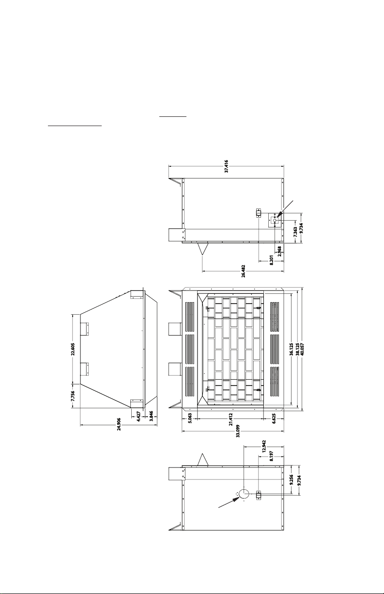
36" MODELS
7.756 22.605
PRODUCT SPECIFICATIONS
37.416
26.482
Firebox Top View
3.846
4.427
24.906
5.063
21.412
33.099
12.942
8.201
6.625
8.197
2.968
Electrical
Outlet
9.734
7.363
38.125
40.057
36.125
Right Side View Right Side View
Front View
Outside Air
Kit Location
(Optional)
Figure 1 - Firebox Dimensions 36'' Models
www.SuperiorFireplaces.US.com
9.256
9.734
126715-01A4
Page 5
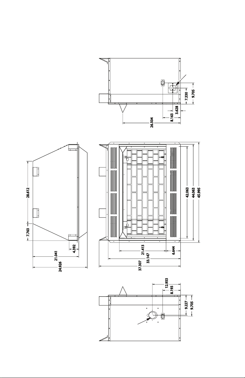
42" MODELS
PRODUCT SPECIFICATIONS
Continued
Firebox Top View
26.504
8.163
3.628
Electrical
Outlet
9.705
7.330
42.063
44.063
45.995
Right Side View Right Side View
Front View
7.763 28.612
21.041
24.926
4.392
21.413
37.307
Outside Air
Kit Location
(Optional)
33.147
12.933
8.193
6.644
9.227
9.705
Figure 2 - Firebox Dimensions 42'' Models
126715-01A 5
www.SuperiorFireplaces.US.com
Page 6

AIR FOR COMBUSTION AND VENTILATION
WARNING: This heater shall
not be installed in a room or space
unless the required volume of indoor combustion air is provided
by the method described in the
National Fuel Gas Code, ANSI
Z223.1/NFPA 54, the International
Fuel Gas Code, or applicable
local codes. Read the following
instructions to insure proper fresh
air for this and other fuel-burning
appliances in your home.
Today’s homes are built more energy efcient
than ever. New materials, increased insulation
and new construction methods help reduce
heat loss in homes. Home owners weather
strip and caulk around windows and doors
to keep the cold air out and the warm air in.
During heating months, home owners want
their homes as airtight as possible.
While it is good to make your home energy
efcient, your home needs to breathe. Fresh
air must enter your home. All fuel-burning ap-
pliances need fresh air for proper combustion
and ventilation.
Exhaust fans, reboxes, clothes dryers and
fuel burning appliances draw air from the
house to operate. You must provide adequate
fresh air for these appliances. This will insure
proper venting of vented fuel-burning appli-
ances.
PROVIDING ADEQUATE
VENTILATION
The following are excerpts from National Fuel
Gas Code, ANSI Z223.1/NFPA 54, Air for
Combustion and Ventilation.
All spaces in homes fall into one of the three
following ventilation classications:
1. Unusually Tight Construction
2. Unconned Space
3. Conned Space
The information on page 5 through 7 will help
you classify your space and provide adequate
ventilation.
Unusually Tight Construction
The air that leaks around doors and windows
may provide enough fresh air for combustion
and ventilation. However, in buildings of un-
usually tight construction, you must provide
additional fresh air.
Unusually tight construction is dened as
construction where:
a. walls and ceilings exposed to the out-
side atmosphere have a continuous
water vapor retarder with a rating of
one perm (6 x 10
less with openings gasketed or sealed
and
b. weather stripping has been added on
openable windows and doors and
c. caulking or sealants are applied to
areas such as joints around window
and door frames, between sole plates
and oors, between wall-ceiling joints,
between wall panels, at penetrations
for plumbing, electrical and gas lines
and at other openings.
If your home meets all of the three criteria
above, you must provide additional fresh
air. See Ventilation Air From Outdoors,
page 8.
If your home does not meet all of the three
criteria above, proceed to Determining
Fresh-Air Flow for Firebox Location,
page 7.
Conned and Unconned Space
The National Fuel Gas Code, ANSI Z223.1/
NFPA 54 denes a conned space as a space
whose volume is less than 50 cubic feet per
1,000 Btu per hour (4.8 m3 per kw) of the aggregate input rating of all appliances installed
in that space and an unconned space as a
space whose volume is not less than 50 cubic
feet per 1,000 Btu per hour (4.8 m3 per kw)
of the aggregate input rating of all appliances
installed in that space. Rooms communicating
directly with the space in which the appliances
are installed*, through openings not furnished
with doors, are considered a part of the unconned space.
* Adjoining rooms are communicating only if
there are doorless passageways or ventilation
grills between them.
-11
kg per pa-sec-m2) or
www.SuperiorFireplaces.US.com
126715-01A6
Page 7
AIR FOR COMBUSTION AND VENTILATION
Continued
DETERMINING FRESH-AIR FLOW
FOR HEATER LOCATION
Determining if You Have a Conned or
Unconned Space
Use this work sheet to determine if you have
a conned or unconned space.
Space: Includes the room in which you will
install heater plus any adjoining rooms with
doorless passageways or ventilation grills
between the rooms.
1. Determine the volume of the space (length
x width x height).
Length x Width x Height = ______cu. ft.
(volume of space)
Example: Space size 22 ft. (length) x 18
ft. (width) x 8 ft. (ceiling height) = 3168 cu.
ft. (volume of space)
If additional ventilation to adjoining room
is supplied with grills or openings, add the
volume of these rooms to the total volume
of the space.
2. Multiply the space volume by 20 to determine the maximum Btu/Hr the space can
support.
_____ (volume of space) x 20 = (Maxi-
mum Btu/Hr the space can support)
Example: 3168 cu. ft. (volume of space) x
20 = 63,360 (maximum Btu/Hr the space
can support)
3. Add the Btu/Hr of all fuel burning appliances in the space.
Vent-free heater _______ Btu/Hr
Gas water heater* _______ Btu/Hr
Gas furnace _______ Btu/Hr
Vented gas heater _______ Btu/Hr
Gas replace logs _______ Btu/Hr
Other gas appliances* + ______ Btu/Hr
Total = ______ Btu/Hr
* Do not include direct-vent gas appli-
ances. Direct-vent draws combustion
air from the outdoors and vents to the
outdoors.
Example:
Gas water heater _________ Btu/Hr
Vent-free heater + ________ Btu/Hr
Total = ________ Btu/Hr
40,000
39,000
79,000
4. Compare the maximum Btu/Hr the space
can support with the actual amount of
Btu/Hr used.
_________ Btu/Hr (maximum the space
can support)
_________ Btu/Hr (actual amount of
Btu/Hr used)
Example: 63,360 Btu/Hr (maximum the
space can support)
79,000 Btu/Hr (actual amount
of Btu/Hr used)
The space in the above example is a conned
space because the actual Btu/Hr used is more
than the maximum Btu/Hr the space can sup-
port. You must provide additional fresh air.
Your options are as follows:
A. Rework worksheet, adding the space
of an adjoining room. If the extra space
provides an unconned space, remove
door to adjoining room or add ventilation
grills between rooms. See Ventilation Air
From Inside Building, page 8.
B. Vent room directly to the outdoors. See
Ventilation Air From Outdoors, page 8.
C. Install a lower Btu/Hr heater, if lower
Btu/Hr size makes room unconned.
If the actual Btu/Hr used is less than the
maximum Btu/Hr the space can support, the
space is an unconned space. You will need
no additional fresh air ventilation.
WARNING: If the area in which
the heater may be operated does
not meet the required volume for
indoor combustion air, combustion and ventilation air shall be
provided by one of the methods
described in the National Fuel
Gas Code, ANSI Z223.1/NFPA 54,
the International Fuel Gas Code,
or applicable local codes.
126715-01A 7
www.SuperiorFireplaces.US.com
Page 8
AIR FOR COMBUSTION AND VENTILATION
Continued
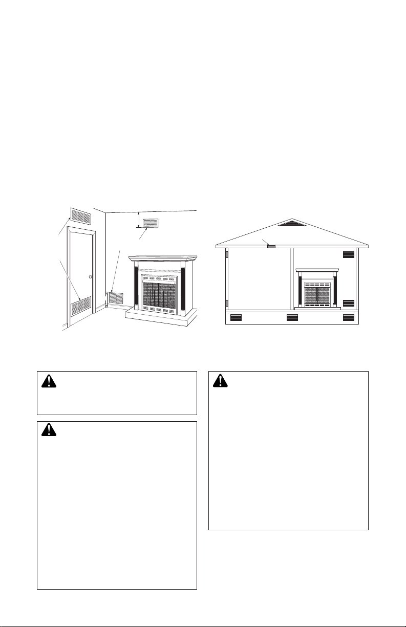
VENTILATION AIR
Ventilation Air From Inside Building
This fresh air would come from an adjoining
unconned space. When ventilating to an
adjoining unconned space, you must provide
two permanent openings: one within 12" of the
ceiling and one within 12" of the oor on the
wall connecting the two spaces (see options
1 and 2, Figure 3). You can also remove door
into adjoining room (see option 3, Figure 3).
Follow the National Fuel Gas Code, ANSI
Z223.1/NFPA 54, Air for Combustion and
Ventilation for required size of ventilation
grills or ducts.
12"
Ventilation
Grills
Into Adjoining
Room,
Option 1
Or
Remove
Door into
Adjoining
Room,
Option
3
Figure 3 - Ventilation Air from Inside
Ventilation Grills
Into Adjoining Room,
12"
Building
Option 2
INSTALLATION
Ventilation Air From Outdoors
Provide extra fresh air by using ventilation
grills or ducts. You must provide two permanent openings: one within 12" of the ceiling
and one within 12" of the oor. Connect these
items directly to the outdoors or spaces open
to the outdoors. These spaces include attics
and crawl spaces. Follow the National Fuel
Gas Code, ANSI Z223.1/NFPA 54, Air for
Combustion and Ventilation for required size
of ventilation grills or ducts.
IMPORTANT: Do not provide openings for
inlet or outlet air into attic if attic has a thermo-
stat-controlled power vent. Heated air entering
the attic will activate the power vent.
Ventilated
Attic
Crawl Space
Ventilated
To Attic
To
Crawl
Space
Outlet
Air
Inlet
Air
Outlet
Air
Inlet Air
Figure 4 - Ventilation Air from Outdoors
WARNING: A qualied service person must install rebox.
Follow all local codes.
WARNING: Never install the
rebox
• in a bedroom or bathroom*
• in a recreational vehicle
• where curtains, furniture, cloth-
ing or other ammable objects
are less than 42" from the front,
top or sides of the rebox
• in high trafc areas
• in windy or drafty areas
* Unless the installed log set is
rated at 10,000 Btu/Hr or less
in a bedroom or 6,000 Btu/Hr
or less in a bathroom.
www.SuperiorFireplaces.US.com
CAUTION: Log heaters
installed in this rebox create
warm air currents. These currents move heat to wall surfaces
next to rebox. Installing rebox
next to vinyl or cloth wall coverings or operating rebox where
impurities (such as, but not
limited to, tobacco smoke, aromatic candles, cleaning uids,
oil or kerosene lamps, etc.) in
the air exist, may discolor walls
or cause odors.
126715-01A8
Page 9

INSTALLATION
Continued
IMPORTANT: Vent-free gas log heaters add
moisture to the air. Although this is benecial,
installing firebox in rooms without enough
ventilation air may cause mildew to form from
too much moisture. See Air for Combustion
and Ventilation, page 6.
IMPORTANT: Make sure rebox is level. If re-
box is not level, log set will not work properly.
Note: Your rebox is designed to be used in zero
clearance installations. Wall or framing material can
be placed against any exterior surface on the rear,
sides, top or bottom of your rebox, except where
standoff spacers are integrally attached. If standoff
spacers are attached to your rebox, these spacers can be placed directly against wall or framing
materials. Use the dimensions shown for rough
opening to create the easiest installation.
Use dimensions shown for rough openings
to create the easiest installation (see Built-In
Firebox Installation, page 10).
INSTALLATION CLEARANCES
WARNING: Maintain the
minimum clearances. If you can,
provide greater clearances from
oor, ceiling and adjoining wall.
Carefully follow these instructions. This will
ensure safe installation.
Minimum Wall and Ceiling Clearances (see
Figure 5)
A. Clearances from the side of fireplace
cabinet to any combustible material and
wall should follow diagram in Figure 5.
Example: The face of a mantel, bookshelf,
etc. is made of combustible material and
protrudes 3 1/2" from the wall. This com-
bustible material must be 4" from the side
of the replace cabinet (see Figure 5).
B. Clearances from the top of rebox opening
to ceiling should not be less than 42".
C. When rebox is installed on carpeting or
other combustible material, other than
wood ooring, rebox should be installed
on a metal or wood panel extending the
full width and depth of enclosure.
D. Clearances from bottom of rebox to the
oor is 0".
These reboxes can be installed as freestanding
units against a wall with the approved, optional
cabinet mantels (see Accessories, page 17) or as
a built-in unit. Clearances are the same for either
installation method.
126715-01A 9
www.SuperiorFireplaces.US.com
CAUTION: Do not install re-
box directly on carpet or vinyl.
Example
*
*Minimum 16" from Side Wall
Figure 5 - Minimum Clearance for
Combustible to Wall
Mantel Clearances for Built-In Installation
If placing custom mantel above built-in rebox,
you must meet the minimum allowable clearance between mantel shelf and top of rebox
opening shown in Figure 6, page 10. These
are the minimum allowable mantel clearances
for a safe installation. Use larger clearances
wherever possible to minimize the heating of
objects and materials placed on the mantel.
CAUTION: Do not allow
the vent-free gas log heater
to touch or extend beyond the
replace screen.
NOTICE: Surface temperatures
of adjacent walls and mantels become hot during operation. Walls
and mantels above the rebox
may become hot to the touch.
If installed properly, these temperatures meet the requirement
of the national product standard.
Follow all minimum clearances
shown in this manual.
NOTICE: If your installation does
not meet the minimum clearances
shown, you must do one of the
following:
• raise the mantel to an accept-
able height
• remove the mantel
Page 10

INSTALLATION
Depth
(Minimum)
Width
(Inside to Inside)
Height
Supplied
Firebox Hood
Must Be Used
at All Times
Wire-mesh
Screen
Firebox
Noncombustible
Material May
Project Off this
Surface above
the Firebox Hood
Mantel Shelf
Note: Any portion of the
mantel shelf must NOT
extend beyond this profile.
12" 16" 20"
1
1
/
2
"
6
3
/
4
"
12"
Note: All vertical
measurements are
from top of fireplace
hood opening to
bottom of mantel shelf.
These minimum
clearances replace any
other recommended
clearances supplied
with your ANSI Z21.11.2
approved gas logs.
Wall board or facing
material (above
firebox) may be of
combustible material,
including decorative
mantel ornaments or
other similar projections off of the facing
material.
Framing
Material
Continued
BUILT-IN FIREBOX INSTALLATION
Built-in installation of this rebox involves
installing rebox into a framed-in enclosure.
This makes the front of rebox ush with wall.
Optional brass trim accessories are available
(see Accessories, page 17). The brass trim
will extend past sides of rebox approximately
1/2". This will cover the rough edges of the
wall opening. If installing a mantel above the
rebox, you must follow the clearances shown
in Figure 6. Follow the instructions below to
install the rebox in this manner.
1. Frame in rough opening. The firebox
framing should be constructed of 2 x 4
lumber or heavier. Use dimensions in the
table and rough opening layout in Figure
7a. Adjust framing so that rebox ushes
with nished wall surface. If installing in a
corner, use dimensions in Figures 7b for
rough opening.
2. Install gas piping to rebox location. See
Installing Gas Line, page 11 and Connecting to Gas Supply in log set owner’s
manual.
3. Carefully set rebox in front of rough opening with back of rebox inside wall open-
ing. IMPORTANT: If installing a perimeter
trim kit, see instructions included with
trim accessory. You must install shoulder
screws from trim kit now.
4.
Carefully insert rebox into rough opening.
5. Attach rebox to wall studs using nails
or wood screws through holes in nailing
ange (see Figure 7).
6. If using an optional perimeter trim kit,
install the trim after nal nishing and/or
painting of wall. See instructions included
with trim accessory for attaching trim.
7. Install and properly test gas log heater.
Follow installation instructions included
with the vent-free gas log heater that is
being installed.
IMPORTANT: When nishing your rebox,
combustible materials such as wall board,
gypsum board, sheet rock, drywall, plywood,
etc. may be butted up next to the sides and top
of the rebox. Combustible materials should
never overlap the rebox front facing.
Rough Opening Dimensions for
Built-in Installation
Model
Front Width
(Inside to Inside) Height
Depth
(Min.)
36" 38 1/4" 37 5/8" 22"
42" 44 1/4" 37 5/8" 22"
Figure
7a
Figure 6 - Minimum Mantel Clearances
for Built-In Installation
Figure
7b
(36'') 47
(42'') 52
Figure 7 - Rough Opening for Installing
www.SuperiorFireplaces.US.com
3
/8"
1
/2"
(36'') 66 7/8"
7
/8"
(42'') 72
in Wall
126715-01A10
Page 11

INSTALLATION
Continued
WARNING: Do not allow any
combustible materials to overlap
the rebox front facing.
IMPORTANT: Noncombustible materials such
as brick, tile, etc. may overlap the front facing,
but should never cover any necessary openings like louvered slots.
WARNING: Do not allow
noncombustible materials to
cover any necessary openings
like louvered slots.
WARNING: Use only noncombustible mortar or adhesives when overlapping the front
facing with noncombustible
facing material.
Nails or
Wood
Screws
INSTALLING FIREBOX USING
OPTIONAL ACCESSORY MANTELS
WARNING: A qualied service person must install rebox.
Follow all local codes.
This rebox may be installed using a cabinet
mantel accessory against a wall in your
home. The rebox and cabinet mantel can
be installed directly on the oor. A trim kit is
included with the mantel accessories. Follow
instructions with mantel for installation.
INSTALLING GAS LINE
NOTICE: A qualied service person must connect heater to gas
supply. Follow all local codes.
IMPORTANT: See Connecting to Gas Supply
in your log set owner’s manual for details on
gas hookup.
You may run the gas line from either side of
the rebox (see Figure 9). Decide which side
you want to run the gas line from.
Note: This is one option for installing shutoff
valve. Check local codes for equipment shutoff valve location requirements.
Equipment Shutoff
Valves (Install One)
Nailing
Flanges
Figure 8 - Attaching Firebox to Wall
126715-01A 11
Studs
www.SuperiorFireplaces.US.com
Knockout
Locations
(Knock Out
One Hole)
Equipment Shutoff Valve (Model May
Gas Line Hole
Figure 9 - Installing Gas Line and
Vary From Illustration)
Page 12

INSTALLATION
Continued
USING OPTIONAL FIBER PANELS
There is a gas knockout in each side panel
for the gas line to feed through. Determine on
which side the gas connection will be located.
Using a utility knife or cutting blade, remove
the identied gas knockout.
CAUTION: Do not use excessive force to remove the
knockout. Too much force may
damage the ber panel.
1/2" Thick Liner
Firebrick Side Wall
Knockout
Figure 10 - Location of Knockout for
Gas Line
WARNING: DO NOT FILL THE
SPACES AROUND THE FIREBOX WITH INSULATION OR
OTHER MATERIALS.
Side View
Remove
This Area
INSTALLING OPTIONAL BLOWER
ACCESSORY
NOTICE: The rebox identication label (including model number, serial number, clearances,
etc.) is located in the right side
screen pocket area on the front
of the rebox. See Figure 19,
page 17.
NOTICE: If a log set is installed
in the rebox, disconnect log
set from gas supply and remove
from rebox. Contact a qualied
service person to do this.
Note: Appearance of rebox may vary depending on model.
There is one (1) blower accessory option
for use with this replace. Blower accessory
model BK . Model BK is a rotary squirrel cage
type blower with magnetic attachment and
variable speed control.
Wiring Instructions
1. Remove electrical cover plate with bushing from replace by removing 2 sheet
metal screws as shown in Figure 11, page
13.
2. Slide power source wiring through electri-
cal bushing opening and electrical cover
plate and make all necessary connections.
3. Slide all wiring connections in electrical
housing as shown in Figure 11, page 13.
4. Secure electrical cover plate with screws
previously removed.
Note: Electrical housing and cover plate have
sharp edges. Wear protective gloves.
WARNING: DO NOT ALTER,
CUT, OR MODIFY FIREPLACE
SPACERS.
www.SuperiorFireplaces.US.com
WARNING: FRAMING MAY BE
PLACED OR REST AGAINST
FIREPLACE SPACER, HOWEVER, FRAMING MUST NEVER
BE NOTCHED.
126715-01A12
Page 13

INSTALLATION
Continued
Sheet
Metal
Screws
Rocker
Switch
Electrical
Housing
Receptacle
(Supplied)
Prewired Receptacle
and Ground
Figure 11 - Fan Switch-Electrical Bushing
Decide which way you intend to gain access
into the bottom rear of the rebox to install the
blower accessory. The lower front panel can
be removed easily by snapping out the front
with a at blade screwdriver. Use caution not
to scratch any surfaces. Models with louvered
front panels can also be removed by inserting
ngertips between slots and gently pulling out.
DO NOT FORCE. The panels are actually
held in place by means of a retention dimple
embossed on the edge of removable panels.
Accessibility to the bottom on 36" and 42"
models only, can also be gained through the
access cover plate on the bottom front of the
rebox hearth. Remove the screws to expose
the rectangular shaped access panel (see
Figure 12). The sides and back refractory
brick liner pieces do not have to be removed
(if installed). Lift access panel out by using
nger holes. Blower accessory BK can now
be installed.
Wire Nut (3x)
(Not Supplied)
Electrical
Bushing
Power Source Wiring
(Not Supplied)
Fireplace Chassis
Ground
Electrical
Cover
Plate
Outer Wrapper
of Fireplace
To Power
Source
Electrical Cover
Plate and
Electrical Bushing
Screws
Access
Cover Plate
Figure 12 - Removing Access Cover Plate
WARNING: If there is a duplex
electrical outlet installed in the
right side of the bottom of the
replace base area (see Figure
13), be sure that the electrical
power to the outlet is turned off
before proceeding with blower
installation. Failure to do this
may result in serious injury.
Duplex Electrical Outlet
Figure 13 - Accessing Duplex Electrical
Outlet Installed in Bottom Right Side of
Firebox
126715-01A 13
www.SuperiorFireplaces.US.com
Page 14

INSTALLATION
Continued
Model BK Installation
1. Be certain that all wire terminals are
securely attached to terminals on blower
motor and that the screw retaining the
green ground wire is tight (see Figure 14).
2. Place blower against lower rear wall of
rebox outer wrapper with exhaust port
directed upward. Depending on your
model, you may have to carefully route
the blower assembly past controls and
brackets and position blower inside
back opening. The blower will be held in
position against the back wall by magnets
incorporated onto blower housing (see
Figure 14).
CAUTION: Use gloves as
sheet metal parts may be sharp.
Control
Knob
Lock
Nut
Control
Shaft
Spade
Terminals
Green
Ground
Wire
Blower
Installed
After
Lower
Panel
Removed
Figure 14 - Blower Model BK
3. Using pliers, remove lock nut from speed
control by turning counter clockwise.
Mount speed control box by placing
plastic control shaft through hole on left
or right side of the rebox hearth by sliding control box down through large hole
in rebox bottom and up through hole
(see Figure 15). Secure speed control to
rebox hearth with previously removed
lock nut with pliers by pushing and turning lock nut until it is tight against rebox
hearth of replace (see Figure 15).
Screw
Side View
Firebox Bottom
Magnetic Strips
Exhaust
Port
Air Flow
Direction
Blower
Location
Magnets
Firebox
Hearth
Figure 15 -Attaching Speed Control
(Model May Vary From Illustration)
4. Check to make sure power cord is completely clear of blower wheel and there
are no foreign objects in blower wheel.
Also, double check all wire leads and
make sure wire routing is not pinched
or in a precarious position. Correct accordingly.
www.SuperiorFireplaces.US.com
126715-01A14
Page 15

INSTALLATION
Variable
Continued
CAUTION: Never touch a
blower wheel while in operation.
5. Turn on power to duplex outlet if previously turned off per warning in column
2, page 13.
6. Plug in blower power cord to duplex
outlet (see Figure 13, page 13).
7. Turn blower on and check for operation.
Turn blower off by turning knob fully
counterclockwise before continuing.
8. Peel off backing paper and stick supplied
wiring diagram decal on rebox bottom
approximately 12" in front of blower (see
Figure 16).
9. Replace all panels if previously removed.
Fan Switch
1
110/115
V.A.C.
Off
Black
Green
White
2
On
Black
Blower
Motor
Wiring Diagram
Decal 12" in
Front of Blower
Figure 16 - Location of Wiring Diagram
Decal (Model May Vary From Illustration)
126715-01A 15
www.SuperiorFireplaces.US.com
Page 16

INSTALLATION
Continued
OPTIONAL OUTSIDE AIR KIT
(MODEL AK4/AK4F)
Installation of outside air kit should be performed during rough framing of replace due
to the nature of it's location. Outside combustion air is accessed through a vented crawl
space (AK4F) or through a sidewall (AK4).
See Figure 17.
CAUTION: Combustion air
inlet ducts shall not terminate
in attic space.
Secure to Collars with Metal Tape, Screws
or Straps (Min. of 1/4" x 20" in size)
Air Inlet
Location
Must Allow
For Bushes
or Snow
Air Inlet
Vented Crawl Space
(Check Local Codes
Before Installing in a
Vented Crawl Space)
Figure 17 - Outside Air Kit
Eyebrow
Vent Hood
Required for
Wall Installation
INSTALLING FIREPLACE HOOD
AND SCREEN
1. Attach hood to rebox using screws pro-
vided (see Figure 18).
2. Insert each rod through all rings located
at top of screen.
3. Insert rst rod into rear hole in left side
of rebox. Fasten rod to rear hole near
center of rebox using #10 x 3/8" Phillips
screw provided (see Figure 19).
4. Insert other rod into front hole on right
side of rebox and fasten using remaining
Phillips screw.
Hood
Screws
Figure 18 - Screw and Hood Placement
(Model May Vary From Illustration)
Top View of Rod Layout
Rear Hole
Front
Hole
Rod
Ring
Screen
Figure 19 - Installing Fireplace Screen
(Model May Vary From Illustration)
www.SuperiorFireplaces.US.com
Identication
Label Location
Screw
126715-01A16
Page 17

REPLACEMENT PARTS
If this product is missing a part or has a broken
component, please do not return it to the store.
Call INNOVATIVE HEARTH PRODUCTS at
1-800-655-2008 to answer questions and
replace parts under warranty.
Note: Use only original replacement parts.
This will protect your warranty coverage for
parts replaced under warranty.
TECHNICAL SERVICE
You may have further questions about instal-
lation, operation, or troubleshooting. If so,
contact INNOVATIVE HEARTH PRODUCTS
at 1-800-655-2008.
ACCESSORIES
NOTICE: All accessories may
not be available for all replace
models.
Purchase these accessories from your local
dealer. If they can not supply these accessories
call INNOVATIVE HEARTH PRODUCTS at
1-800-655-2008 for information. You can also
write to the address listed on the back page
of this manual.
OUTSIDE AIR KIT
AK4 - Complete Kit w/ Collar, Hood & 3' of
Flex Tube
Optional kit provide additional air to reduce
build-up of condensation that occurs in
today’s tightly constructed homes.
AK4F - Outside Air Kit for Floor Installation.
BLOWER KIT
BK - Squirrel Cage Blower With Speed
Control.
When calling or writing, please have your
model and serial numbers of your replace
ready.
Model and serial number information are in the
replace's rating plate located in the screen
pocket to the left or right of the face opening.
When calling please have your model and
serial numbers of your heater ready.
You can also visit INNOVATIVE HEARTH
PRODUCTS’s web site at www.IHP.US.com.
RUNNING BOND CERAMIC FIBER
BRICK LINER KITS
BLB36SF - 36" Stacked Red
BLB42SF - 42" Stacked Red
RUNNING BOND REFRACTORY
BRICK LINER KITS
BLB36SR - 36" Stacked White
BLB42SR - 42" Stacked White
126715-01A 17
www.SuperiorFireplaces.US.com
Page 18

PARTS
MODELS VRT2036B, VCT2036B, VRT2036WS, VCT2036WS,
VRT2042B, VCT2042B, VRT2042WS, AND VCT2042WS
8
7
5
4
3
2
6
7
13
12
9
10
11
1
www.SuperiorFireplaces.US.com
5
126715-01A18
Page 19

PARTS
This list contains replaceable parts used in your rebox. When ordering parts, follow the
instructions listed under Replacement Parts on page 17 of this manual.
KEY
NO. PART NO. DESCRIPTION QTY.
1 107127-01 Screen • • • • 2
108424-01 Screen • • • • 2
2 20806 Screen Rod • • • • 2
108790-01 Screen Rod • • • • 2
3 11418 Push-On Nut • • • • • • • • 2
4 123494-01 Hood, Deector • • • • 1
123494-02 Hood, Deector • • • • 1
5 124483-01 Side Refractory White Stack • • • • 2
6 124484-01 Rear Refractory White Stack • • 1
124485-01 Rear Refractory White Stack • • 1
7 20027 Refractory Bracket • • • • 2
8 20280 Top, Spacer • • • • • • • • 4
9 107128-01 Conduit, Gas • • • • • • • • 4
10 110037-01 Electrical Duct Assembly • • • • • • • • 1
11 21198 Plate, Blower Access • • • • • • • • 1
12 21171 Cover, Gas Conduit • • • • 3
21171 Cover, Gas Conduit • • • • 2
13 126250-01 Bracket, Retaining • • • • 2
VRT2036B
VCT2036B
VRT2036WS
VRT2042B
VCT2042B
VRT2042WS
VCT2036WS
VCT2042WS
126715-01A 19
www.SuperiorFireplaces.US.com
Page 20

Innovative Hearth Products
Superior™ Brand Gas Fireplaces, Stoves and Inserts
20 Year Limited Warranty
THE WARRANTY
Innovative Hearth Products ("IHP") 20 Year Limited Warranty warrants your Superior™ Brand gas fireplace, Stove or Insert ("Product") to be free from defects in materials
and workmanship at the time of manufacture. The Product body and firebox carry the 20 Year Limited Warranty. Ceramic glass carries the 20 Year Limited Warranty against
thermal breakage only. After installation, if covered components manufactured by IHP are found to be defective in materials or workmanship during the 20 Year Limited
Warranty period and while the Product remains at the site of the original installation, IHP will, at its option, repair or replace the covered components. If repair or replacement
is not commercially practical, IHP will, at its option, refund the purchase price or wholesale price of the IHP product, whichever is applicable. IHP will also pay IHP prevailing labor rates, as determined in its sole discretion, incurred in repairing or replacing such components for up to five years. THERE ARE EXCLUSIONS AND LIMITATIONS
to this 20 Year Limited Warranty as described herein.
COVERAGE COMMENCEMENT DATE
Warranty coverage begins on the date of installation. In the case of new home construction, warranty coverage begins on the date of first occupancy of the dwelling or six
months after the sale of the Product by an independent IHP dealer/distributor, whichever occurs earlier. The warranty shall commence no later than 24 months following
the date of product shipment from IHP, regardless of the installation or occupancy date.
EXCLUSIONS AND LIMITATIONS
This 20 Year Limited Warranty applies only if the Product is installed in the United States or Canada and only if operated and maintained in accordance with the printed
instructions accompanying the Product and in compliance with all applicable installation and building codes and good trade practices.
This warranty is non-transferable and extends to the original owner only. The Product must be purchased through a listed supplier of IHP and proof of purchase must be
provided. The Product body and firebox carry the 20 Year Limited Warranty from the date of installation. Vent components, trim components and paint are excluded from
this 20 Year Limited Warranty. The following do not carry the 20 Year Limited Warranty but are warranted as follows:
Burner – Repair or replacement for one year from the date of installation
Gas components – Repair or replacement for one year from the date of installation
Gaskets – Repair or replacement for one year from the date of installation
Logs – Replacement for one year from the date of installation against thermal breakage only
Optional blowers & remote controls – Repair or replacement for one year from the date of installation
Optional glass doors – Repair or replacement for 90 days from the date of installation
Tempered glass - Replacement for one year from the date of installation
Labor coverage – Prevailing IHP labor rates apply for the warranty period of the component
Parts not otherwise listed carry a 90 day warranty from the date of installation.
Whenever practicable, IHP will provide replacement parts, if available, for a period of 10 years from the last date of manufacture of the Product.
IHP will not be responsible for: (a) damages caused by normal wear and tear, accident, riot, fire, flood or acts of God; (b) damages caused by abuse, negligence, misuse, or
unauthorized alteration or repair of the Product affecting its stability or performance (The Product must be subjected to normal use. The Product is designed to burn either
natural or propane gas only. Burning conventional fuels such as wood, coal or any other solid fuel will cause damage to the Product, will produce excessive temperatures
and could result in a fire hazard.); (c) damages caused by failing to provide proper maintenance and service in accordance with the instructions provided with the Product;
(d) damages, repairs or inefficiency resulting from faulty installation or application of the Product.
IHP is not responsible for inadequate fireplace system draft caused by air conditioning and heating systems, mechanical ventilation systems, or general construction conditions which may generate negative pressure in the room in which the appliance is installed. Additionally IHP assumes no responsibility for drafting conditions caused by
venting configurations, adjoining trees or buildings, adverse wind conditions or unusual environmental factors and conditions that affect the operation of the unit.
This 20 Year Limited Warranty covers only parts and labor as provided herein. In no case shall IHP be responsible for materials, components or construction, which are not
manufactured or supplied by IHP or for the labor necessary to install, repair or remove such materials, components or construction. Additional utility bills incurred due to
any malfunction or defect in equipment are not covered by this warranty. All replacement or repair components will be shipped F.O.B. from the nearest stocking IHP factory.
LIMITATION ON LIABILITY
It is expressly agreed and understood that IHP’s sole obligation and the purchaser’s exclusive remedy under this warranty, under any other warranty, expressed or implied,
or in contract, tort or otherwise, shall be limited to replacement, repair, or refund, as specified herein.
In no event shall IHP be liable for any incidental or consequential damages caused by defects in the Product, whether such damage occurs or is discovered before or
after repair or replacement, and whether such damage is caused by IHP’s negligence. IHP has not made and does not make any representation or warranty of fitness for a
particular use or purpose, and there is no implied condition of fitness for a particular use or purpose.
IHP makes no expressed warranties except as stated in this 20 Year Limited Warranty. The duration of any implied warranty is limited to the duration of this expressed warranty.
No one is authorized to change this 20 Year Limited Warranty or to create for IHP any other obligation or liability in connection with the Product. Some states and provinces
do not allow the exclusion or limitation of incidental or consequential damages, so the above limitations or exclusions may not apply to you. The provisions of this 20 Year
Limited Warranty are in addition to and not a modification of or subtraction from any statutory warranties and other rights and remedies provided by law.
INVESTIGATION OF CLAIMS AGAINST WARRANTY
IHP reserves the right to investigate any and all claims against this 20 Year Limited Warranty and to decide, in its sole discretion, upon the method of settlement.
To receive the benefits and advantages described in this 20 Year Limited Warranty, the appliance must be installed and repaired by a licensed contractor approved by IHP.
Contact IHP at the address provided herein to obtain a listing of approved dealers/distributors. IHP shall in no event be responsible for any warranty work done by a
contractor that is not approved without first obtaining IHP's prior written consent.
HOW TO REGISTER A CLAIM AGAINST WARRANTY
In order for any claim under this warranty to be valid, you must contact the IHP dealer/distributor from which you purchased the product. If you cannot locate the dealer/
distributor, then you must notify IHP in writing. IHP must be notified of the claimed defect in writing within 90 days of the date of failure. Notices should be directed to the
IHP Warranty Department at 1508 Elm Hill Pike, Suite 108; Nashville, TN 37210 or visit our website at WWW.SUPERIORFIREPLACES.US.COM.
Printed in U.S.A. © 2013 Innovative Hearth Products LLC
P/N 900223-00, Rev. NC 12/2013
Innovative Hearth Products
1508ElmHillPike,Suite108•Nashville,TN37210
Page 21

KEEP THIS WARRANTY
Model (
located on product or identication tag
Serial No. (
located on product or identication tag
Date Purchased __________________________
Keep receipt for warranty verication.
) _____________________________
) __________________________
Page 22

NOTES
22
Page 23

NOTES
23
Page 24

P126715-01
1508 Elm Hill Pike, Suite 108
Nashville, TN 37210
1-800-655-2008
www.IHP.US.com
126715-01
Rev. A
02/14
 Loading...