

Superior Vantage Engine O-360 SERIES, Vantage Engine IO-360 SERIES Maintenance Manual
O-360 & IO-360 SERIES ENGINES
MAINTENANCE MANUAL
621 South Royal Lane, Suite 100 / Coppell, TX 75019 / 800-277-5168
www.superiorairparts.com
Manual P/N SVMM01, Revision B, February 2007
© February 2007 Superior Air Parts Inc.
i
RW
02-00-00
Description and Operation

Maintenance Manual
O-360 and IO-360 Series Engines
THIS
PAGE
INTENTIONALLY
LEFT
BLANK
ii
© February 2007 Superior Air Parts Inc.
General Information

Maintenance Manual
O-360 and IO-360 Series Engines
Manual Number SVMM01
Revision History
Revision
Letter
IR 02/27/06 Initial Release All
A 3/6/06
B 02/28/07
Effective
Date
Description
SAP CR# 8004, del magneto 100 hr insp. from ALS, add “or
annual” to & del mag cap removal from 100 hr insp
Add Celsius Temperature conversions to Fahrenheit
temperatures
Pages
Revised
05-00-00, p1
05-20-00, p3
72-00-10 All
72-00-12 All
72030-00 All
72-50-00 All
iii
© February 2007 Superior Air Parts Inc.
General Information

Maintenance Manual
O-360 and IO-360 Series Engines
THIS
PAGE
INTENTIONALLY
LEFT
BLANK
iv
© February 2007 Superior Air Parts Inc.
General Information

Maintenance Manual
O-360 and IO-360 Series Engines
SAFETY ADVISORY
WARNING: BEFORE MATERIALS CALLED OUT IN THIS PUBLICATION ARE USED, KNOW THE
HANDLING, STORAGE AND DISPOSAL PRECAUTIONS RECOMMENDED BY THE
MANUFACTURER OR SUPPLIER. FAILURE TO COMPLY WITH THE
MANUFACTURER’S OR SUPPLIER’S RECOMMENDATION CAN RESULT IN
PERSONAL INJURY.
CAUTION: INFORMATION IS TO EMPHASIZE INSTRUCTIONS OR PREVENT POSSIBLE
EQUIPMENT DAMAGE.
The user must know the manufacturer or supplier information and obey the procedures,
recommendations, warnings, and cautions set forth for the use, handling, storage, and disposal of
materials.
The WARNINGS used in this manual inform the user about dangerous materials or equipment that can
cause injury. They do not replace the manufacturer's instructions.
This Safety Advisory has all the warnings included in this manual.
WARNING: OPERATION OF A DEFECTIVE ENGINE WITHOUT A PRELIMINARY EXAMINATION
CAN CAUSE FURTHER DAMAGE TO A DISABLED COMPONENT AND POSSIBLE
INJURY TO PERSONNEL. MAKE SURE THOROUGH INSPECTION AND
TROUBLESHOOTING PROCEDURES ARE ACCOMPLISHED. THIS WILL HELP TO
PREVENT INJURIES TO PERSONNEL AND/OR DAMAGE TO THE EQUIPMENT.
WARNING: FUEL IS TOXIC AND FLAMMABLE. DO NOT BREATHE VAPORS. USE IN A WELL-
VENTILATED AREA FREE FROM SPARKS, FLAME, OR HOT SURFACES. PUT ON
SPLASH GOGGLES, SOLVENT-RESISTANT GLOVES, AND OTHER PROTECTIVE
GEAR. IN CASE OF EYE CONTACT, FLUSH WITH WATER FOR 15 MINUTES AND
SEEK MEDICAL ATTENTION. IN CASE OF SKIN CONTACT, WASH WITH SOAP AND
WATER.
WARNING: HOT OIL MAY CAUSE BURNS TO EYES AND SKIN. PUT ON SPLASH GOGGLES,
INSULATED GLOVES, AND OTHER PROTECTIVE GEAR. IN CASE OF EYE
CONTACT, FLUSH WITH WATER FOR 15 MINUTES AND SEEK MEDICAL
ATTENTION. IN CASE OF SKIN CONTACT, WASH WITH SOAP AND WATER.
WARNING: DO NOT INSTALL THE IGNITION HARNESS "B" NUTS ON THE SPARK PLUGS UNTIL
THE PROPELLER INSTALLATION IS COMPLETED. FAILURE TO COMPLY COULD
RESULT IN BODILY INJURY WHEN THE PROPELLER IS ROTATED DURING
INSTALLATION.
WARNING: SOLVENT IS TOXIC. USE IN WELL-VENTILATED AREA. PREVENT EYE AND SKIN
CONTACT AND DO NOT BREATHE VAPORS. IN CASE OF EYE CONTACT, FLUSH
WITH WATER. IN CASE OF SKIN CONTACT, WASH WITH SOAP AND WATER.
v
© February 2007 Superior Air Parts Inc.
General Information

Maintenance Manual
O-360 and IO-360 Series Engines
WARNING: WHEN YOU USE COMPRESSED AIR TO CLEAN OR DRY PARTS, MAKE SURE THAT
THE PRESSURE IS NOT MORE THAN 30 PSI. DO NOT DIRECT THE AIRSTREAM AT
PERSONNEL OR LIGHT OBJECTS. PUT ON GOGGLES OR A FACE SHIELD TO
PROTECT YOUR EYES. THIS WILL HELP PREVENT INJURIES TO PERSONNEL OR
DAMAGE TO THE EQUIPMENT. IF YOU HAVE AN EYE INJURY, GET MEDICAL
ATTENTION.
WARNING: USE METHYL ETHYL KETONE (MEK) SOLVENT CORRECTLY. THE SOLVENT IS
FLAMMABLE AND REACTIVE. IT CAN HAVE A BAD EFFECT ON YOUR HEALTH OR
SAFETY. BEFORE YOU USE THE SOLVENT, GET THE MATERIAL SAFETY DATA
SHEET (MSDS) FROM THE MANUFACTURER OR SUPPLIER OF THE MATERIAL
AND READ IT CAREFULLY. BEFORE YOU USE THE SOLVENT, PUT ON SAFETY
SPLASH GOGGLES, SOLVENT-RESISTANT GLOVES (BUTYL RUBBER), RUBBER
APRON, AND CHEMICAL-SAFETY SHOES. MAKE SURE THAT YOU HAVE
SUFFICIENT AIRFLOW TO KEEP THE SOLVENT FUMES BELOW THE MSDS LIMIT.
WARNING: ENGINE OIL IS HAZARDOUS AND MAY CAUSE INJURY TO SKIN AND EYES. PUT
ON RUBBER GLOVES AND GOGGLES.
WARNING: PLACE A SUITABLE STAND UNDER THE AIRCRAFT TAILCONE IF NEEDED BEFORE
REMOVING THE ENGINE. THE LOSS OF WEIGHT MAY CAUSE THE AIRCRAFT TAIL
TO DROP.
WARNING: USE THE CORRECT PERSONAL PROTECTION. SOME CHEMICAL SOLUTIONS CAN
CAUSE SKIN, EYE AND LUNG DAMAGE. FOLLOW THE MANUFACTURER'S
INSTRUCTIONS FOR EACH CLEANING SOLUTION.
WARNING: TO PREVENT THE POSSIBILITY OF SERIOUS BODILY INJURY OR DEATH, BEFORE
MOVING THE PROPELLER DO THE FOLLOWING:
• DO NOT STAND WITHIN THE ARC OF THE PROPELLER BLADES WHILE
TURNING THE PROPELLER.
• VERIFY ALL SPARK PLUG LEADS ARE DISCONNECTED.
• VERIFY MAGNETO SWITCHES ARE CONNECTED TO MAGNETOS AND THAT
THEY ARE IN THE “OFF” POSITION AND P-LEADS ARE GROUNDED.
• THROTTLE POSITION “CLOSED”.
• MIXTURE CONTROL POSITION “IDLE-CUT OFF”.
• SET BRAKES AND BLOCK AIRCRAFT WHEELS. ENSURE THAT AIRCRAFT
• TIE DOWNS ARE INSTALLED AND VERIFY THAT THE CABIN DOOR LATCH IS
OPEN.
vi
© February 2007 Superior Air Parts Inc.
General Information

Section
Chapter
General Information
Sub-Section
Revision History iii
Safety Advisory v
Table of Contents vii
List of Figures xi
List of Tables xiii
Maintenance Manual
O-360 and IO-360 Series Engines
TABLE OF CONTENTS
Page Number
01 00 00 Introduction
02 00 00 Description and Operation
04 00 00 Airworthiness Limitations Section
05 00 00 Scheduled Inspection and Maintenance
20 00
50 00
About This Manual 1
Related Publications 1
Obtaining Revisions to Instructions for Continued
Airworthiness
General Description 1
Continued Airworthiness 1
Model Designations 1
Engine Components General Description 3
Specifications 3
Features and Operating Mechanisms 5
Mandatory Replacement Time 1
Mandatory Inspection Intervals 1
General 1
25 Hour Inspection 1
50 Hour Inspection 1
100 Hour or Annual Inspection 3
500 Hour Inspection 6
1000 Hour Inspection 6
Recommended TBO 6
Recommended Accessory Replacement 6
Unscheduled Inspection and Maintenance 1
1
vii
© February 2007 Superior Air Parts Inc.
General Information

Section
Chapter
72 00 00 Engine Section
Sub-Section
General 1
Maintenance Manual
O-360 and IO-360 Series Engines
TABLE OF CONTENTS (cont’d)
Page Number
01 Testing a nd Fault Isolation
05 Engine Removal
06 Engine Disassembly
07 Cleaning
General 1
Troubleshooting 1
General 1
Removal 1
Preservation 1
General 1
General 1
Cleaning Instructions 1
Overall Engine Cleaning 1
Spark Plugs and Electrical Components 1
Oil System Components 2
Degreasing 2
Decarbonizing 2
Corrosion Removal 3
Parts Preservation and Corrosion Prevention 3
09 Engine Assembly
10 Engine Installation
11 Torque s, Fits, and Clearances
© February 2007 Superior Air Parts Inc.
General 1
General 1
Preparing Engine for Service 1
Installation of Engine 1
General 1
Service Limits 1
viii
General Information

Maintenance Manual
O-360 and IO-360 Series Engines
Section
Chapter
72 00 12 Preservation and Storage
Sub-Section
General 1
Temporary Storage 2
Indefinite Storage 3
Returning an Engine To Service After Storage 3
TABLE OF CONTENTS (cont’d)
Page Number
00 13 Repair Procedures
15 Servicing
10 00 Front Section
30 00 Cylinder Section
50 00 Lubrication Section
General 1
General 1
Fuels 1
Lubricants 1
Consumables 2
General 1
Starter 1
Alternator 3
Propeller Governor System 6
General 1
Cylinder Replacement 1
Cylinder Break-in Procedures 10
General 1
Oil Pressure Adjustment 1
Oil Filter Adapter and Vernatherm Valve 1
Oil Sump Suction Screen 2
© February 2007 Superior Air Parts Inc.
ix
General Information

Section
Chapter
73 00 00 Engine Fuel System
Sub-Section
General 1
Fuel System Leaks 1
Fuel Pump Replacement 3
Fuel Screen 3
Maintenance Manual
O-360 and IO-360 Series Engines
TABLE OF CONTENTS (cont’d)
Page Number
10 00 Fuel Injection System
20 00 Carburetion System
74 00 00 Ignition Section
Fuel Injector Nozzle Cleaning 1
Idle Speed and Mixture Adjustment 1
Primer Nozzle Cleaning 1
General 1
Magneto Replacement 1
Ignition Harness Replacement 2
Appendix 1
Unison Industries L-1363B, 4300/6300 Series Magneto
Maintenance and Overhaul Manual
x
© February 2007 Superior Air Parts Inc.
General Information

Maintenance Manual
O-360 and IO-360 Series Engines
LIST OF FIGURES
Figure
02-00-00.1 Engine Model Number Designation 02 00 00 2
02-00-00.2 O-360 Engine Front View 7
02-00-00.3 O-360 Engine Left Side View 8
02-00-00.4 O-360 Engine Top View 9
02-00-00.5 O-360 Engine Rear View 10
02-00-00.6 IO-360 Engine Front View 11
02-00-00.7 IO-360 Engine Left Side View 12
02-00-00.8 IO-360 Engine Top View 13
02-00-00.9 IO-360 Engine Rear View 14
72-10-00.1 Starter Installation 72 10 00 2
72-10-00.2 Alternator Installation 3
72-10-00.3 Alternator and Mounting Hardware Detail 5
72-10-00.4 Propeller Governor Oil Line 7
72-30-00.1 Assembled Cylinders 30 00 3
72-30-00.2 Piston Pin and Piston Assembly 4
72-30-00.3 Piston Ring Compressor 5
72-30-00.4 Cylinder Base Nut Tightening Sequence 6
72-30-00.5 Installation of Pushrods 7
72-30-00.6 Rocker Arm and Pushrod Assembly 8
72-30-00.5 Intercylinder Baffle Assembly 9
Section
Chapter
Page
Sub-Section
72-50-00.1 Oil System Schematic 50 00 2
72-50-00.2 Oil Filter and Adapter Assembly 3
72-50-00.3 Oil Sump Assembly 5
72-50-00.4 Oil Pressure Relief Valve 6
73-00-00.1 Engine Fuel Pump Assembly 73 00 00 2
74-00-00.1 Magneto Components 74 00 00 3
74-00-00.2 Timing Diagram 4
74-00-00.3 Ignition Wiring Diagram 5
xi
© February 2007 Superior Air Parts Inc.
General Information

Maintenance Manual
O-360 and IO-360 Series Engines
THIS
PAGE
INTENTIONALLY
LEFT
BLANK
xii
© February 2007 Superior Air Parts Inc.
General Information

Maintenance Manual
O-360 and IO-360 Series Engines
LIST OF TABLES
Table
Section
Chapter
01-00-00.1 Special Tools and Equipment 01 00 00 1
02-00-00.1 General Specifications 02 00 00 3
02-00-00.2 Accessory Drive Specifications 3
02-00-00.3 Manufacturer’s Physical Specifications 4
02-00-00.4 Primary Engine Accessories 4
02-00-00.5 Illustrated Views of the Engine 5
02-00-00.6 Secondary Engine Accessories 5
05-00-00.1 Scheduled Inspection and Maintenance Intervals 05 00 00 1
72-00-01.1 Abnormal Operation Troubleshooting Procedures 72 00 01 1
72-00-01.2 Engine Will Not Start 2
72-00-01.3 Rough Idling 2
72-00-01.4 Engine Not Able To Develop Full Power 2
72-00-01.5 Rough Engine Operation 3
72-00-01.6 Low Power & Engine Runs Rough 3
72-00-01.7 Low Oil Pressure On Engine Gage 3
72-00-01.8 High Oil Temperature 4
72-00-01.9 Excessive Oil Consumption 4
Page
Sub-Section
72-00-05.1 Equipment and Materials List 05 1
72-00-07.1 Equipment Required for Cleaning 07 1
72-00-07.2 Materials Required for Cleaning 1
72-00-10.1 Equipment and Materials List 10 1
72-00-11.1 Dimensional Limits 11 2
72-00-11.2 Backlash and End Clearance Limits 2
72-00-11.3 Torque Limits 3
72-00-11.4 Valve Spring Dimensional Limits 4
72-00-11.5 Crush Type Gasket Tightening Angles 4
72-00-12.1 Preservation and Storage Materials 12 1
xiii
© February 2007 Superior Air Parts Inc.
General Information

Maintenance Manual
O-360 and IO-360 Series Engines
LIST OF TABLES (cont’d)
Table
Section
Chapter
Sub-Section
72-00-15.1 Oil Grades 72 00 15 1
72-00-15.2 Oil Sump Capacity 1
72-00-15.3 Minimum Octane Fuels 2
72-00-15.4 Consumables 2
72-00-15.4 Hoses 2
72-10-00.1 Alternator Belt Tension Requirements 10 00 4
72-30-00.1 Equipment and Material List 30 00 1
72-50-00.1 Oil Pressure Springs 50 00 1
73-00-00.1 List of Materials 73 00 00 1
74-00-00.1 List of Equipment 74 00 00 1
Page
xiv
© February 2007 Superior Air Parts Inc.
General Information

Maintenance Manual
O-360 and IO-360 Series Engines
INTRODUCTION
About This Manual
Information contained in this Engine
Maintenance Manual fulfills the content
requirements of FAR 33.4 Appendix A33.3(a)
and has been found acceptable to the Federal
Aviation Administration (FAA). The purpose of
this Maintenance Manual is to provide the
necessary instructions for performing
maintenance on the Superior Vantage Engine.
Repair and replacement information may be
found in the overhaul manual.
The information in this publication is based on
data available at the time of publication and is
updated, supplemented, and automatically
amended by Publication Revisions and Service
Bulletins that are issued by Superior Air Parts.
This manual is divided into separate sections
relating to the general and specific maintenance
instructions required for the engine. These
general and specific instructions are organized
and numbered per the recommendations of the
General Aviation Manufacturers Association
(GAMA). In this way, information may be
located in a conventional manner to aid in both
accuracy and timeliness.
Page numbering is organized within each
section. The section number (e.g., 72-00-01) is
displayed in the right hand section of the footer
on each page. The page number is displayed in
the center of the footer on each page.
All measurements are noted in English (U.S.)
units. Conventional unit abbreviations are used.
Be sure to ground magneto P-leads prior to any
maintenance and perform normal pre-run
checks and inspections upon completion any
maintenance.
Superior Air Parts has made clear and accurate
information available for those who maintain,
own and repair the Vantage O-360 and IO-360
Series Engines. Superior Air Parts values your
input regarding revisions and additional
information for our manuals. Please forward
your comments and input to:
Superior Air Parts
Attn: Engineering Department
621 South Royal Lane Suite 100
Coppell, Texas 75019
Table 01-00-00.1 • Special Tools and Equipment
Item Vendor
Electrical Tester Commercially Available
Related Publications
The following are related engine publications.
• SVIOM01, O-360 & IO-360 Installation and
Operation Manual
• SVOHM01, O-360 & IO-360 Overhaul
Manual
Obtaining Revisions to Instructions for
Continued Airworthiness
All Vantage Engine manuals and service
information may be downloaded at
www.superiorairparts.com
Or may be purchased by contacting:
Superior Air Parts
621 South Royal Lane, Suite 100
Coppell, Texas 75019
or call: 972-829-4600
1
© March 2006 Superior Air Parts Inc.
01-00-00
Introduction

Maintenance Manual
O-360 and IO-360 Series Engines
THIS
PAGE
INTENTIONALLY
LEFT
BLANK
2
© March 2006 Superior Air Parts Inc.
01-00-00
Introduction

Maintenance Manual
O-360 and IO-360 Series Engines
DESCRIPTION AND OPERATION
General Description
Superior Vantage Engines are four-cylinder,
horizontally opposed, air-cooled, direct drive
powerplants incorporating a wet sump, bottom
mounted induction, bottom exhaust with either
carbureted or port injected fuel systems.
Provisions exist for both front and rear mounted
accessories. All engine components will be
referenced as they are installed in the airframe.
Therefore, the “front” of the engine is the
propeller end and the “rear” of the engine is the
accessory mounting drive area. The oil sump is
on the “bottom” of the engine and the cylinder
shroud tubes are on the “top”. The terms “left”
and “right” are defined as being viewed from the
rear of the engine looking toward the front.
Cylinder numbering is from the front to the rear
with odd numbered cylinders on the right side of
the engine. The direction of crankshaft rotation
is clockwise as viewed from the rear of the
engine looking forward unless otherwise
specified. Accessory drive rotation direction is
defined as viewed from the rear of the engine
looking forward.
Continued Airworthiness
Vantage Engines discussed in this document
must be installed and operated in accordance
with the limitations, conditions and operating
procedures described in the Installation and
Operation Manual (SVIOM01). They must also
be maintained and repaired in accordance with
this manual and the Overhaul Manual
(SVOHM01).
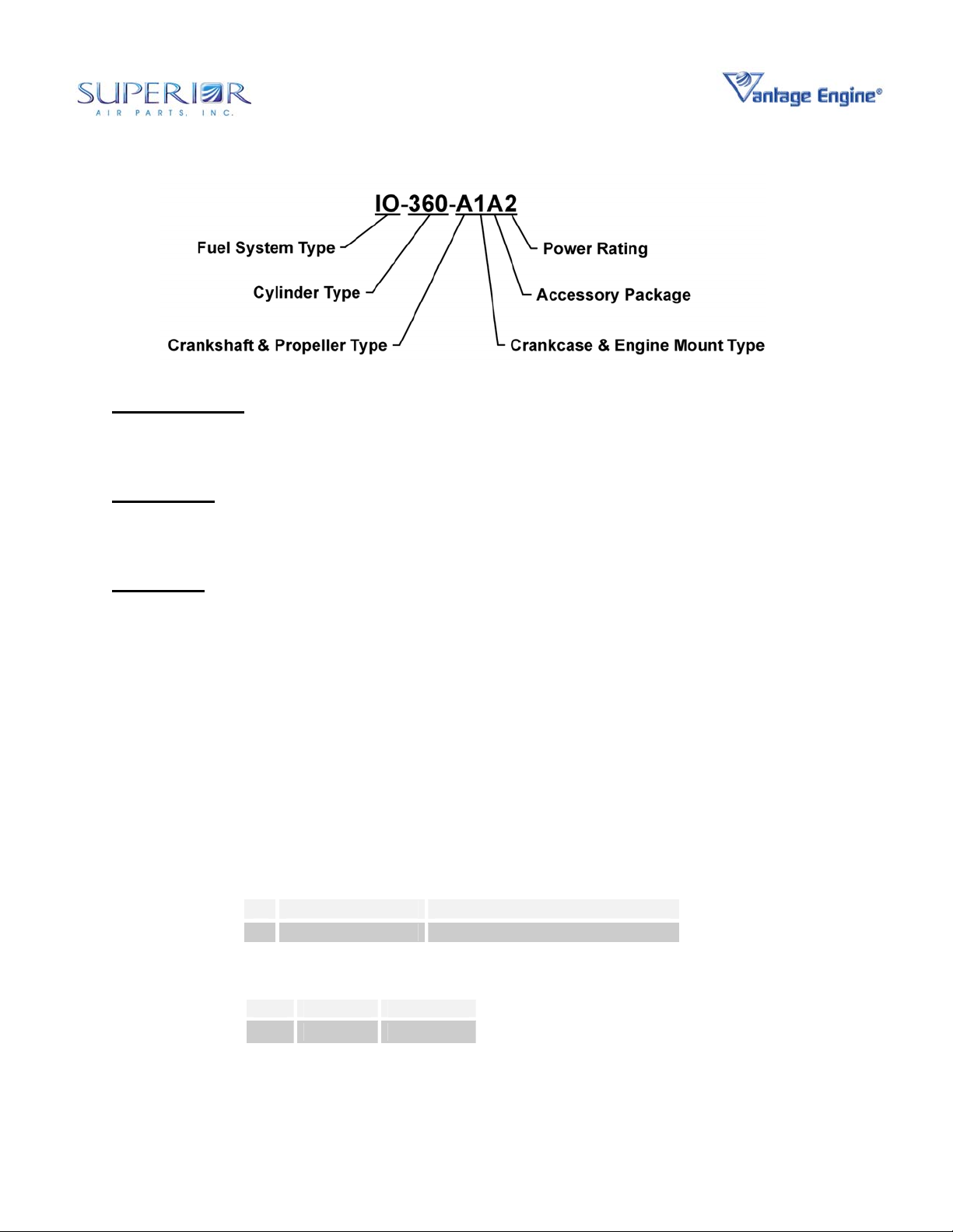
Model Designations
The model number designation is defined in a
way that the digits of the model number can
easily identify the basic configuration of the
engine as described in Figure 02-00-00.1.
Engine Components General Description
The Vantage Engine O-360 and IO-360 series
engines are air-cooled, four cylinder, horizontally
opposed, direct drive engines. See Table 0200-00.1 for General Specifications.
The complete engine includes the following
components and assemblies:
Crankcase Assembly
Crankshaft Assembly
Camshaft Assembly
Valve Train Assembly
Cylinder Assemblies
Connecting Rod Assemblies
Oil Sump Assembly
Intercylinder Baffles
Starter
Lubrication System (Includes Oil Filter)
Accessory Drive
Ignition System (Includes Spark Plugs)
Fuel System
Starter Support Assembly
Oil Level Gage
Induction System
NOTE: Complete engine does not include outer
cylinder baffles, airframe to engine control
cables, attaching hardware, hose clamps,
vacuum pump, exhaust system, or fittings.
Unless otherwise specified, the fuel pump is
included on carbureted engines. Alternator or
propeller governor systems may be included, if
specified the Model Specification Data (MSD) .
1
© March 2006 Superior Air Parts Inc.
02-00-00
Description and Operation
Maintenance Manual
O-360 and IO-360 Series Engines
Fuel System Type
O Denotes a Carbureted system and “opposed cylinder” arrangemen t.
IO Denotes a Fuel Injection system and “opposed cylinder” arrangement.
Cylinder Type
360 Parallel valve cylinder, 361 cubic inches.
Model Suffix
1st Digit Crankshaft & Propeller Type
A Fixed-Pitch, Thin-wall front main
B Constant-Speed, Thin-wall front main
C Fixed-Pitch, Heavy-wall front main
D Constant-Speed, Heavy-wall front main
E Fixed-Pitch, Solid front main
2nd Digit Crankcase & Engine Mount Type
3rd Digit Accessory Package
4th Digit Power Rating: Piston Compression Ratio
Denotes detail engine configuration
1 #1 Dynafocal Mount
2 #2 Dynafocal Mount
3 Conical Mount
4 #1 Dynafocal Mount, Front Propeller Governor
5 #2 Dynafocal Mount, Front Propeller Governor
6 Conical Mount, Front Propeller Governor
Ignition System Fuel System
A Unison Magnetos Precision Fuel System
CR HP
2 8.5:1 180
Figure 02-00-00.1 • Engine Model Number Designation
2
© March 2006 Superior Air Parts Inc.
02-00-00
Description and Operation
Maintenance Manual
O-360 and IO-360 Series Engines
Specifications
The physical specifications of the O-360 and IO360 series engines are listed in Table 02-00-
00.3. Accessory Drive Specifications are
provided in Table 02-00-00.2. Information on
Primary Accessories, fuel and ignition systems,
are provided in Table 02-00-00.4. The Model
Specification Data (MSD) in the Installation and
Operation Manual may provide more specific
information, such as secondary engine
accessories provided.
Table 02-00-00.1 • General Specifications
Model O-360 and IO-360 series
Rated Power Hp 180
Rated Speed, RPM RPM 2700
Bore, inches In 5.125
Stroke, inches In 4.375
Displacement cubic inches In3 361.0
Compression Ratio 8.5:1
Firing Order 1-3-2-4
Spark timing °BTDC 25
Propeller drive ratio 1:1
Propeller drive rotation
(viewed from rear)
Illustrated views of the O-360 and IO-360
engines identifying key components and subassemblies are provided in Figures 02-00-00.1
thru 02-00-00.9 of this section and are listed in
Table 02-00-00.5 for convenience.
Clockwise
Table 02-00-00.2 • Accessory Drive Specifications
Accessory
Starter 16.556:1 CounterAlternator 3.250:1 Clockwise
Tachometer 0.500:1 Clockwise
Magneto 1.000:1 Clockwise
Vacuum Pump 1.300:1
Propeller Governor 0.866:1 Clockwise
Fuel Pump 0.500:1 Plunger Operated
© March 2006 Superior Air Parts Inc.
Drive
Ratio
3
Direction of
Rotation
Counter-
02-00-00
Description and Operation

Maintenance Manual
O-360 and IO-360 Series Engines
Table 02-00-00.3 • Physical Specifications
Model
O-360-Axxx 24.6 33.4 32.8 288
O-360-Bxxx 24.6 33.4 32.8 291
O-360-Cxxx 24.6 33.4 32.8 291
O-360-Dxxx 24.6 33.4 32.8 294
O-360-Exxx 24.6 33.4 32.8 295
IO-360-Axxx 24.0 33.4 32.8 290
IO-360-Bxxx 24.0 33.4 32.8 293
IO-360-Cxxx 24.0 33.4 32.8
IO-360-Dxxx 24.0 33.4 32.8 296
IO-360-Exxx 24.0 33.4 32.8 297
*Base engine weight with accessories listed in Table 02-00-00.4 below and a 7.8 lb.
starter, the front propeller governor crankcase option adds 7 lb. to the engine weight.
Model
O-360
IO-360
* See Table 72-00-15.4 for approved consumables (spark plugs, oil filters, belts, hoses)
and Table 02-09-00.6 below for approved secondary engine accessories.
Left
Magneto
Unison
4371
Unison
4371
Height
(In)
Table 02-00-00.4 • Primary Engine Accessories*
Right
Magneto
Unison
4371
Unison
4371
Width
(In)
Ignition
Harness
Unison
M4001
Unison
M4001
Length
(In)
Fuel System
Precision
MA-4-5
Precision
RSA-5-AD1
Weight*
(Lb)
293
Fuel Pump
(if furnished)
Aero Accessories
AF15472
Aero Accessories
AF15473
4
© March 2006 Superior Air Parts Inc.
02-00-00
Description and Operation

Maintenance Manual
O-360 and IO-360 Series Engines
Table 02-00-00.5 • Illustrated Views of the Engine
Engine View Figure Number
O-360 Engine Front View Figure 02-00-00.2
O-360 Engine Left Side View Figure 02-00-00.3
O-360 Engine Top View Figure 02-00-00.4
O-360 Engine Rear View Figure 02-00-00.5
IO-360 Engine Front View Figure 02-00-00.6
IO-360 Engine Left Side View Figure 02-00-00.7
IO-360 Engine Top View Figure 02-00-00.8
IO-360 Engine Rear View Figure 02-00-00.9
Table 02-00-00.6 • Secondary Engine Accessories (if provided)
Accessory &
Manufacturer
Starters
Sky-Tec 149-12LS 12 n/a 7.8 pounds
Sky-Tec 149-24LS 24 n/a 7.8 pounds
Sky-Tec 149-NL 12 or 24 n/a 9.4 pounds
Alternators
Kelly Aerospace ALY8520LS 12 60 10.9 pounds
Plane-Power AL12-F60 12 70 9.8 pounds
Plane-Power AL24-F60 24 70 9.8 pounds
Features and Operating Mechanisms
Crankshaft - The crankshaft is made from high
quality, aerospace grade steel. All bearing
journal surfaces are nitrided to surface harden.
There are 3 kinds of crankshafts: thin-wall, thickwall, and solid front mains which can be
identified by looking at the center of the front of
the crankshaft or prop oil cavity. The thin-wall
and thick-wall crankshafts are each available as
fixed-pitch or constant-speed. Fixed-pitch
models have a plug installed in front of the inner
diameter of the front main bearing cavity.
Constant speed models have a plug installed at
the rear of the front main bearing cavity.
Model Voltage Amperage Weight
Connecting Rods - The connecting rods are
made from aerospace grade, high quality steel.
They have replaceable bearing inserts in the
crankshaft ends and bronze bushings in the
piston ends. The bearing caps on the
crankshaft ends are retained by two bolts with
self locking nuts. Caps are tongue and groove
type for improved alignment and rigidity.
Camshaft and Valve Operating Mechanism The camshaft is located above and parallel to
the crankshaft. The camshaft actuates hydraulic
lifters that operate the valves through push rods
and valve rockers.
5
© March 2006 Superior Air Parts Inc.
02-00-00
Description and Operation

Maintenance Manual
O-360 and IO-360 Series Engines
Crankcase - The crankcase is made from
aerospace grade, stabilized structural aluminum
alloy. The assembly consists of two reinforced
aluminum alloy castings fastened together by
means of studs, bolts, and nuts. The main
bearing bores are machined for use with
precision type main bearing inserts.
Accessory Housing - The accessory housing is
made from an aluminum casting and is fastened
to the rear of the crankcase and the top rear of
the sump.
Oil Sump - The sump incorporates an oil drain
plug, oil suction screen, mounting pad for
carburetor or fuel injector, the intake riser, and
intake pipe connections.
Cylinders - Millennium
exclusively. These air-cooled cylinders are
manufactured by screwing and shrinking the two
major parts, head and barrel, together. The cast
heads are made from a special aluminum alloy.
All barrels are made from forgings produced to
aerospace specifications. They are internally
choked and honed to allow optimal operating
conditions for the rings and pistons at operating
temperatures.
Pistons - The pistons are made from an
aluminum alloy. The piston pin is a full floating
type with a plug located in each end of the pin.
The piston is a 3-ring type with 2 compression
rings and 1 oil control ring.
Cooling System – Superior Vantage Engines
are designed to be air-cooled. Baffles are
provided to build up air pressure and force the
air between the cylinder fins. The air is
exhausted to the atmosphere through the rear of
the cowling.
Induction System - The distribution of the air to
each cylinder is through the center zone of the
induction system. This is integral with the oil
sump.
®
Cylinders are used
Lubrication System - The full pressure wet
sump lubrication system is supplied by a gear
type pump. It is contained within the accessory
housing.
Priming System - A manual primer system is
provided on all engines using a carburetor. Fuel
injected engines do not require a manual
priming system, relying instead on the fuel
injectors for priming.
Ignition System - Dual ignition is furnished by
two Unison magnetos with two spark plugs per
cylinder.
Electrical System – Engines may be furnished
with an alternator, if provided for in the model
specification. If an alternator is furnished,
installation brackets, hardware and belt are
provided. Alternators are available in either 12
or 24 volt systems and a range of amperages
Fuel Systems
Carbureted
are equipped with a float type carburetor The
MA-4-5 carburetors are of the single barrel float
type equipped with a manual mixture control and
an idle cut-off.
Fuel Injected
equipped with a direct cylinder injected RSA-5AD1 fuel injection system. The fuel injection
system schedules fuel flow in proportion to
airflow. Fuel vaporization takes place at the
intake ports. The RSA fuel injection system is
based on the principle of measuring airflow and
converting the air pressure into a fuel pressure.
The fuel pressure, when applied across the fuel
metering section, makes fuel flow proportional to
airflow.
- Superior Air Parts O-360 engines
- IO-360 series engines are
6
© February 2007 Superior Air Parts Inc.
Description and Operation
02-00-00

Maintenance Manual
O-360 and IO-360 Series Engines
CHT PROBE LOCATION
(TYPICAL EACH HEAD)
ALTERNATOR & BELT
(IF PROVIDED WITH ENGINE)
SPARK PLUG
SPARK PLUG
PRIMING
SYSTEM
STARTER
THROTTLE LEVER
CARBURETOR
FUEL LINE
Figure 02-00-00.2 • O-360 Engine Front View
7
© March 2006 Superior Air Parts Inc.
02-00-00
Description and Operation
Maintenance Manual
O-360 and IO-360 Series Engines
STARTER SUPPORT
ASSEMBLY
PRIMING
SYSTEM
CRANKCASE
ASSEMBLY
STARTER
INDUCTION
SYSTEM
CYLINDER
ASSEMBLY
SPARK PLUG
OIL SUMP
ASSEMBLY
ACCESSORY
HOUSING
MIXTURE
LEVER
OIL FILTER
FUEL
PUMP
FUEL
LINE
HARNESS
MAGNETO
CARBURETOR
Figure 02-00-00.3 • O-360 Engine Left Side View
8
© March 2006 Superior Air Parts Inc.
02-00-00
Description and Operation
Maintenance Manual
O-360 and IO-360 Series Engines
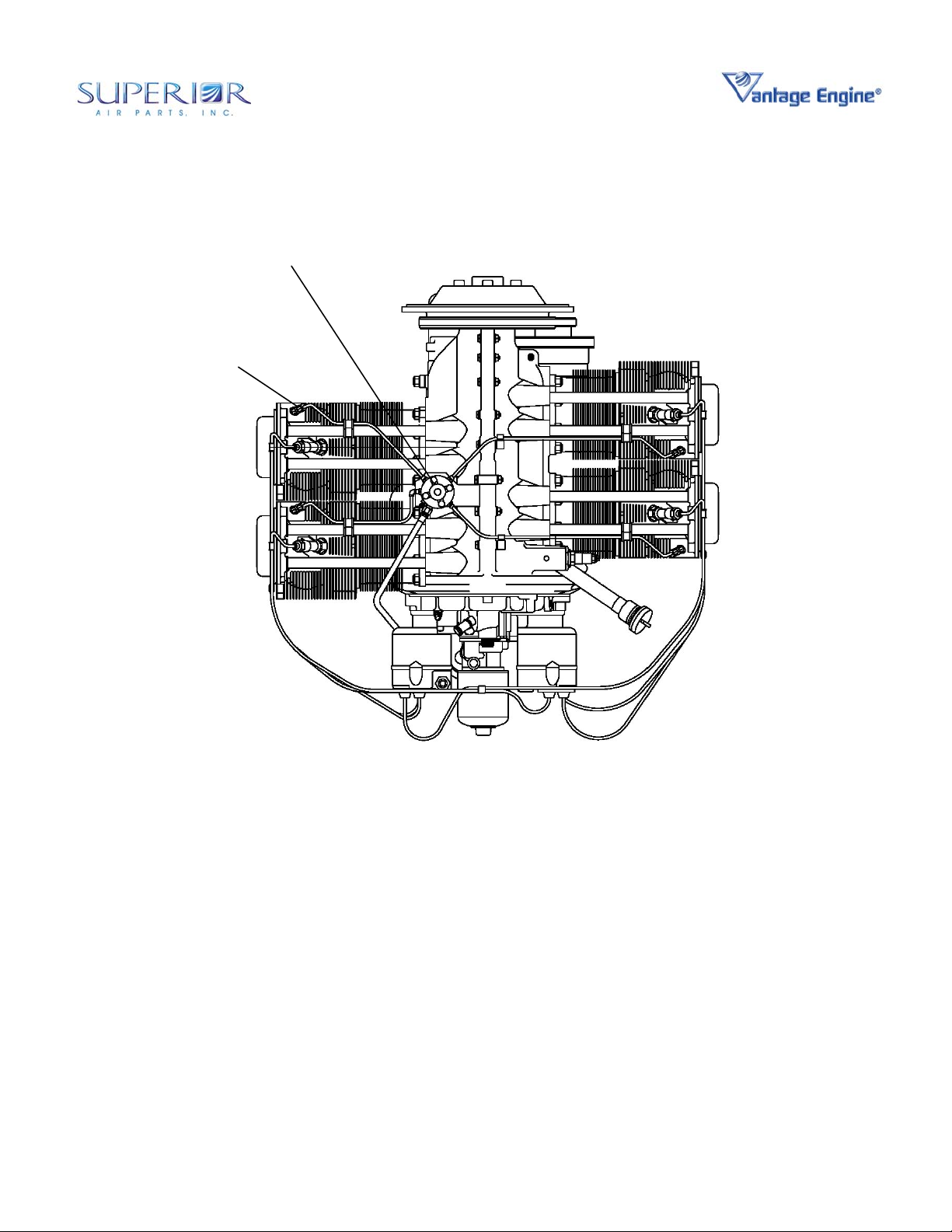
INTER-CYLINDER BAFFLE
SPARK P L U G
MAGNETO
OIL FILTER
Figure 02-00-00.4 • O-360 Engine Top View
© March 2006 Superior Air Parts Inc.
9
MAGNETO
02-00-00
Description and Operation
Maintenance Manual
O-360 and IO-360 Series Engines
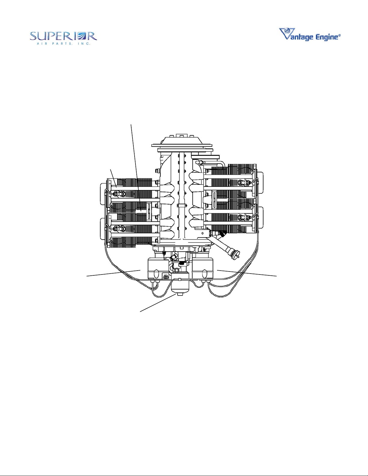
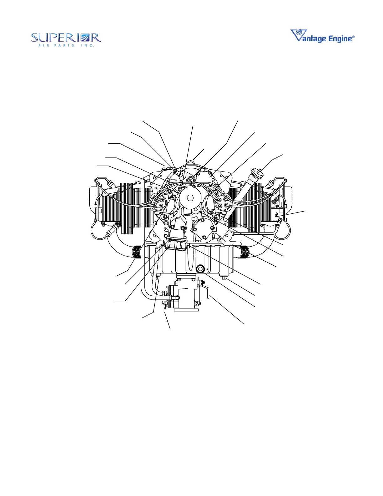
ALTERNATE OIL TO COOLER
OIL TEMP
CONNECTION
BRACKET
EYE
TACHOMETER CONNECTION
OIL RETURN FROM COOLER
OIL FILTER
GROUND OR “P-LEAD” TERMINAL
VENT LINE
CONNECTION
DIAPHRAGM
FUEL PUMP
BREATHER
FUEL LINE
FITTING
FUEL MIXTURE
LEVER
THROTTLE
LEVER
VACUUM PUMP / ACCESSORY PAD
OIL PRESSURE GAGE CONNECTION
OIL DRAIN
PLUG
FUEL PUMP INLET
OIL SUCTION
SCREEN
OIL LEVEL TUBE & GAGE
MANIFOLD
PRESSURE
CONNECTION
GROUND OR “P-LEAD” TERMINAL
OIL SUPPLY TO COOLER
OIL LINE TO
PROPELLER
COMMON PRIMER
LINE SOURCE
Figure 02-00-00.5 • O-360 Engine Rear View
10
© March 2006 Superior Air Parts Inc.
02-00-00
Description and Operation
Maintenance Manual
O-360 and IO-360 Series Engines
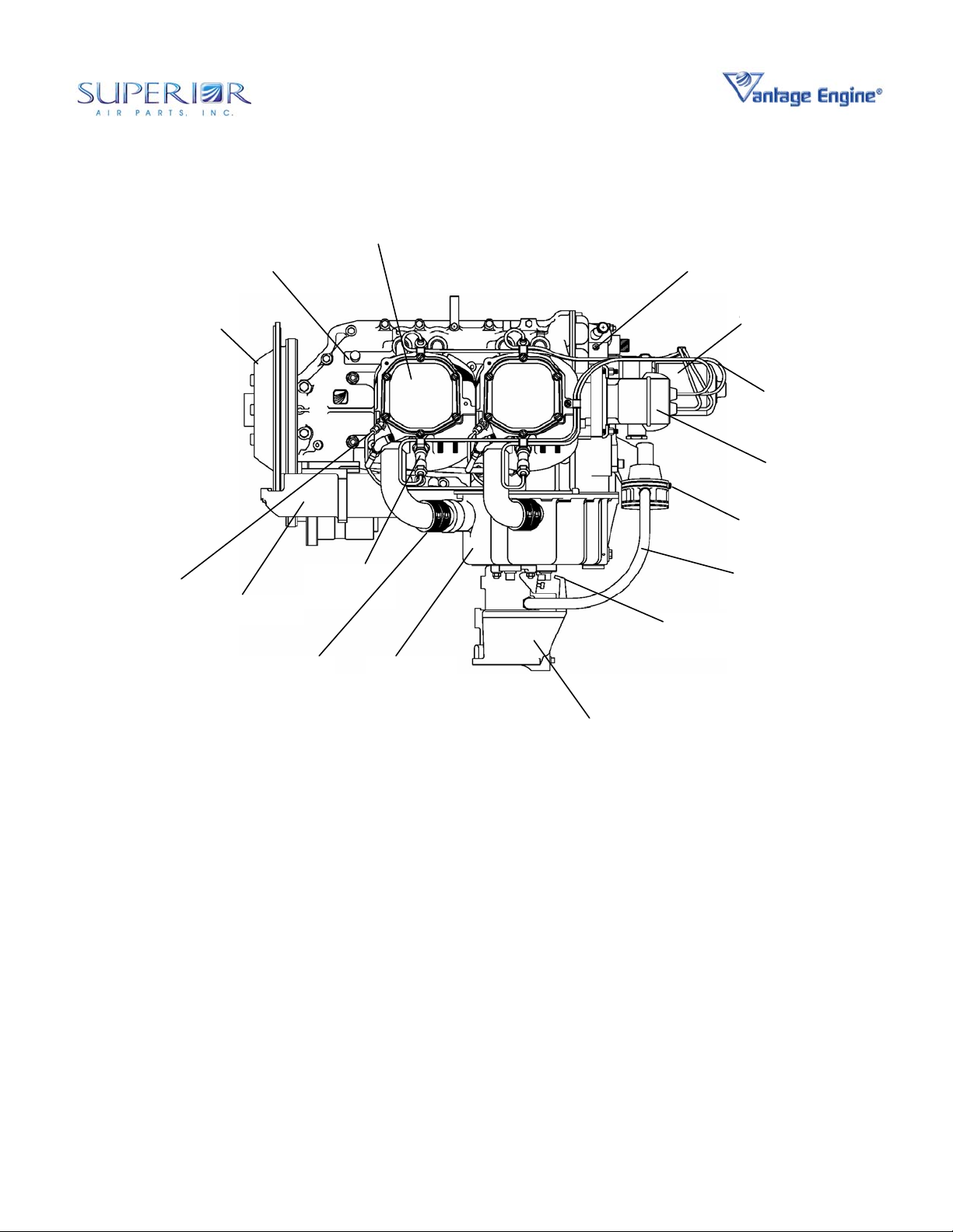
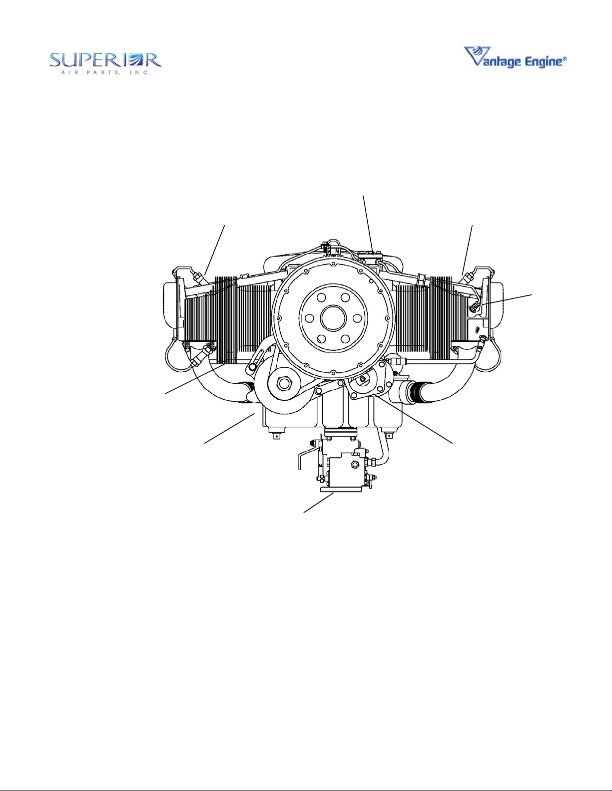
FUEL INJECTION
MANIFOLD
CHT PROBE LOCATION
(TYPICAL EACH HEAD)
(IF PROVIDED WITH ENGINE)
SPARK PLUG
ALTERNATOR & BELT
SPARK PLUG
FUEL
INJECTOR
STARTER
FUEL INJECTION
SERVO
Figure 02-00-00.6 • IO-360 Engine Front View
11
© March 2006 Superior Air Parts Inc.
02-00-00
Description and Operation
Maintenance Manual
O-360 and IO-360 Series Engines
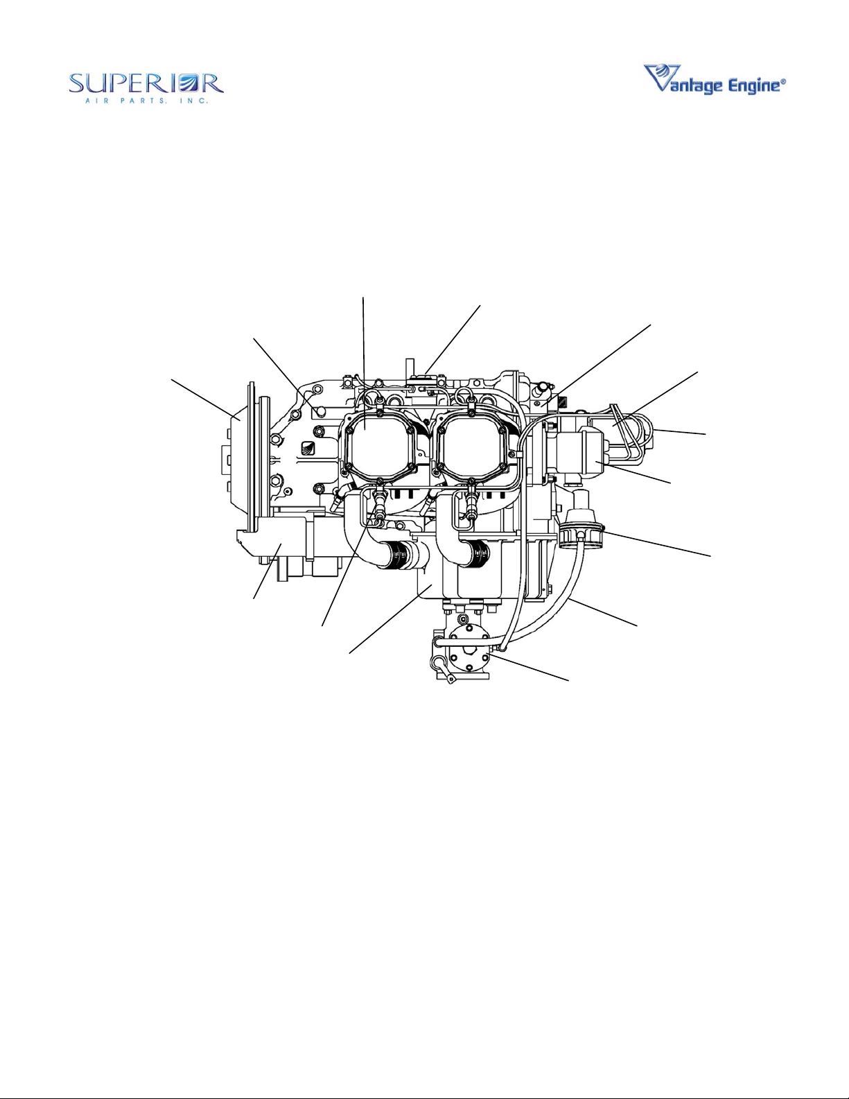
CRANKCASE
ASSEMBLY
CYLINDER
ASSEMBLY
FUEL INJECTION
MANIFOLD
ACCESSORY
HOUSING
STARTER SUPPORT
ASSEMBLY
STARTER
SPARK PLUG
OIL SUMP
FUEL INJECTION
Figure 02-00-00.7 • IO-360 Engine Left Side View
SERVO
MAGNETO
FUEL LINE
OIL FILTER
WIRING
HARNESS
FUEL PUMP
12
© March 2006 Superior Air Parts Inc.
02-00-00
Description and Operation
Maintenance Manual
O-360 and IO-360 Series Engines
FUEL INJECTI ON
MANIFOLD
FUEL INJ ECTIOR
Figure 02-00-00.8 • IO-360 Engine Top View
13
© March 2006 Superior Air Parts Inc.
02-00-00
Description and Operation
Maintenance Manual
O-360 and IO-360 Series Engines
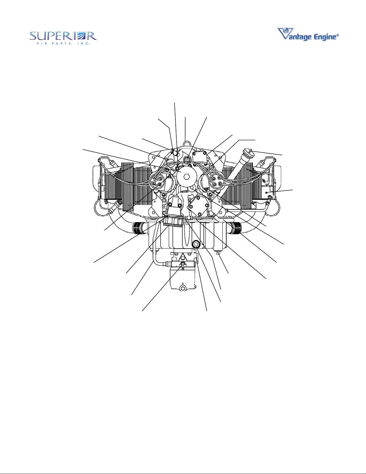
BREATHER FITTING
FUEL INJECTION MANIFOLD
OIL RETURN FROM COOLER
OIL FILTER
GROUND OR “P-LEAD” TERMINAL
VENT LINE CONNECTION
ALTERNATE OIL
TO COOLER
OIL TEMP
CONNECTION
EYE
BRACKET
TACHOMETER CONNECTION
VACCUM PUMP / ACCESSORY PAD
FUEL PUMP INLET
OIL PRESSURE GAGE CONNECTION
OIL LEVEL TUBE & GAGE
MANIFOLD
PRESSURE
CONNECTION
GROUND OR “P-LEAD” TERMINAL
OIL SUPPLY TO COOLER
OIL LINE TO
PROPELLER
DIAPHRAGM FUEL
PUMP
OIL DRAIN PLUG
MIXTURE CONTROL
LEVER
THROTTLE CONTROL
OIL DRAIN PLUG
OIL SUCTION
SCREEN
LEVER
Figure 02-00-00.9 • IO-360 Engine Rear View
14
© March 2006 Superior Air Parts Inc.
02-00-00
Description and Operation
 Loading...