

Page 1
RETAIN THESE INSTRUCTIONS
FOR FUTURE REFERENCE
INSTALLATION
INSTRUCTIONS
STANDARD SERIES
Built-In Unvented Fireboxes
P/N 903761 REV. E 02/2004
MODELS
UVFCE Series
FOR USE ONLY WITH DECORATIVE TYPE UNVENTED ROOM
HEATERS.
DO NOT BUILD A WOOD FIRE.
WARNING: IMPROPER INSTALLATION, ADJUSTMENT, ALTERATION, SERVICE OR MAINTENANCE CAN CAUSE INJURY OR PROPERTY DAMAGE. REFER TO THIS MANUAL.
FOR ASSISTANCE OR ADDITIONAL INFORMATION CONSULT A QUALIFIED INSTALLER, SERVICE AGENCY OR THE
GAS SUPPLIER.
WARNING: IF THE INFORMATION IN THIS MANUAL
IS NOT FOLLOWED EXACTLY, A FIRE OR EXPLOSION MAY RESULT CAUSING PROPERTY DAMAGE,
PERSONAL INJURY OR LOSS OF LIFE.
FOR YOUR SAFETY: Do not store or use gasoline
or other flammable vapors or liquids in the vicinity
of this or any other appliance.
FOR YOUR SAFETY: What to do if you smell gas:
• DO NOT light any appliance.
• DO NOT touch any electrical switches.
• DO NOT use any phone in your building.
• Immediately call your gas supplier from a
neighbor’s phone.
Follow your gas suppliers instructions.
• If your gas supplier cannot be reached, call the
fire department.
Installation and service must be performed by a
qualified installer, service agency or the gas supplier.
NOTE: DIAGRAMS & ILLUSTRATION NOT TO SCALE.
WARNING: DO NOT BURN WOOD OR OTHER MATERIAL IN
THESE APPLIANCES.
CAREFULLY REVIEW THE INSTRUCTIONS SUPPLIED WITH
THE DECORATIVE TYPE UNVENTED ROOM HEATER FOR
THE MINIMUM FIREPLACE SIZE REQUIREMENT.
DO NOT INSTALL THE APPLIANCE IN THIS FIREBOX, UNLESS THIS FIREBOX MEETS THE MINIMUM DIMENSIONS
REQUIRED FOR THE INSTALLATIONS.
This is an unvented gas-fired heater. It uses air
(oxygen) from the room in which it is installed.
Provisions for adequate combustion and ventilation air must be provided. Refer to Combustion
and Ventilation Air Section, Page 3.
Due to high temperatures, the appliance should be located out
of traffic and away from furniture or draperies.
Do not place clothing or other materials on or near this appliance.
IMPORTANT: READ AND UNDERSTAND THESE INSTRUCTIONS
COMPLETELY BEFORE INSTALLING YOUR UNVENTED ROOM
HEATERS.
1
Page 2
TABLE OF CONTENTS
Firebox/Log Set Reference Chart ..... page 2
General Information......................... page 2
Inventory ......................................... page 2
Tools/Building Supplies ...................page 2
Important Safety Information .......... page 2
Codes .............................................. page 3
Combustion and Ventilation Air ....... page 3
Location of firebox........................... page 4
Clearances ....................................... page 4
Assembly Steps ...............................page 5
Gas Line Installation ........................ page 5
Firebox Framing............................... page 6
Firebox Installation .......................... page 6
Firebox Specifications...................... page 7
Framing Specifications .................... page 8
Canopy Installation .......................... page 9
Adjustable Canopy ...........................page 9
Trim Kits .......................................... page 10
Forced Air Kit ................................... page 10
Firebox finishes ............................... page 10
Replacement Parts .......................... page 10
Accessories/Components ................ page 10
Replacement Parts List.................... page 11
Warranty.......................................... page 12
The UVFCE Series are unvented fireboxes.
They feature a self-contained heat-circulating
system.
This installation manual will enable you to
obtain a safe, efficient and dependable installation of your room heater system.
Do not alter or modify the firebox or its components under any circumstances. Any modification or alteration of the firebox system, including but not limited to the firebox and accessories, may void the warranty, listings and
approvals of this system and could result in an
unsafe and potentially dangerous installation.
These Built-In Unvented Fireboxes have been
tested and approved as unvented room heaters
by AGA to ANSI Z21.11.
Check the inventory list to be sure that you have
all the necessary parts in usable condition. Also
check for concealed damage.
Inventory
Unvented Gas Firebox
Canopy
Gas Connector Fittings
Installation and Operating Instructions
Tools and Building Supplies
Normally Required
GENERAL INFORMATION
The Built-In Unvented Fireboxes are designed
to accept all ANSI Z21.11.2 approved Unvented Gas Log Room Heaters. For the appropriate Unvented Gas Log Room Heater model,
refer to the chart below. Refer to the installation instructions provided with the log sets for
detailed instructions.
WARNING: THESE BUILT-IN UNVENTED FIREBOXES HAVE ONLY BEEN TESTED AND
APPROVED FOR USE WITH ANSI Z21.11.2 UNVENTED GAS LOGS.
Tools Should Include:
Phillips screwdriver
Hammer
Saw and/or sabersaw
Level
Measuring tape
Electric drill and bits
Pliers
Square
Piping complying with local codes
Pipe wrench
Tee joint
Pipe compound
Building Supplies Should Include:
Framing materials
Wall finishing materials
Caulking materials (noncombustible)
Fireplace surround materials
(noncombustible)
IMPORTANT SAFETY INFORMATION
INSTALLER: PLEASE LEAVE THESE INSTRUCTIONS WITH THE OWNER.
OWNER: PLEASE RETAIN THESE INSTRUCTION FOR FUTURE REFERENCE
IMPORTANT: BEFORE STARTING YOUR FIREBOX INSTALLATION, READ THESE INSTALLATION INSTRUCTIONS CAREFULLY TO BE SURE
YOU UNDERSTAND THEM COMPLETELY AND
IN ENTIRETY. FAILURE TO FOLLOW THESE
INSTRUCTIONS COULD CAUSE A HEATER
MALFUNCTION RESULTING IN SERIOUS INJURY AND/OR PROPERTY DAMAGE.
WARNING: ANY CHANGE TO THIS UNVENTED ROOM HEATER CAN BE DANGEROUS. IMPROPER INSTALLATION OR
USE OF THIS HEATER CAN CAUSE SERIOUS INJURY OR DEATH FROM FIRE,
BURNS, EXPLOSION OR CARBON MONOXIDE POISONING.
Carbon Monoxide Poisoning: Early signs of
carbon monoxide poisoning are similar to the
flu with headaches, dizziness and/or nausea.
If you have these signs, obtain fresh air immediately. Have the Unvented Gas Heater
serviced as it may not be operating correctly.
DO NOT ATTEMPT TO BURN SOLID WOOD FUELS, OTHER GAS LOG SETS OR ANY OTHER
COMBUSTIBLE MATERIALS IN THIS UNVENTED FIREBOX.
Log Set Sizing Reference Chart
(Shown Sized Wilth Superior Log Sets)
Unvented Firebox Unvented Room Heater Log Set
Model Natural Propane (L.P.G)
UVFCE-40 VFGL-18/21/24MN/VN-3 VFGL-18/21/24MP/VP-3
UVFCE-45 VFGL-24/28MN/VN-3 VFGL-24/28MP/VP-3
Note: 18, 24 and 28 inch gas log sets are available with Rustic Oak and Split Oak logs.
2
• Due to high temperatures, the firebox should
be located out of traffic and away from furniture
and draperies.
• Children and adults should be alerted to the
hazard of high surface temperature and should
stay away to avoid burns or clothing ignition.
NOTE: DIAGRAMS & ILLUSTRATION NOT TO SCALE.
Page 3

• Young children should be carefully supervised when they are in the same room with the
heater.
• Do not place clothing or other flammable
material on or near the heater.
• Any safety screen or guard removed for
servicing the firebox must be replaced and/or
closed prior to operating the heater.
• Installation and repair should be done by a
qualified service person. The heater should be
inspected before use and at least annually by a
professional service person. More frequent
cleaning may be required due to excessive lint
from carpeting, bedding material, etc. It is
important that control compartments, burners
and circulating air passageways of the heater
be kept clean.
• Allow the heater to cool before servicing.
Always shut off any electricity or gas to the
heater while performing service work.
• Do not install the firebox in a sleeping room
or bathroom.
• The installation must conform with local
codes or, in the absence of local codes with the
National Fuel Gas Code, ANSI Z223.1.
• The appliance and its individual shut-off
valve must be disconnected from the gas supply piping system while performing any tests
of the gas supply piping system at pressures in
excess of ¹⁄₂ psig.
• The heater must be isolated from the gas
supply piping system by closing its individual
manual shut-off valve during any pressure
testing of the gas supply piping system at test
pressures equal to or less than ¹⁄₂ psig.
• Keep heater area clear and free from combustible materials, gasoline and other flammable vapors and liquids.
• Do not use this heater if any part has been
under water. Immediately call a qualified service technician to inspect the heater and to
replace any part of the control system and any
gas control which has been under water.
• Ensure that the heater is clean when operating. Excessive dust accumulation on the burner
and logs will increase the amount of carbon
monoxide formation and could lead to carbon
monoxide poisoning and death.
CODES
Adhere to all local codes or in their absence the
latest edition of The National Fuel Gas Code
ANSI Z223.1 or NFPA54 which can be obtained
from The American National Standards Institute, Inc. (1430 Broadway, New York, NY,
10018) or National Fire Protection Association,
Inc. (Batterymarch Park, Quincy, MA, 02269).
COMBUSTION AND VENTILATION AIR
Heaters installed in these appliances shall not
be installed in a confined space. Heaters
installed in these appliances may be located
in unusually tight construction provided the
space is unconfined, or if confined, is provided with two permanent openings communicating directly with an additional room(s)
of sufficient volume so that the combined
volume of all connected spaces meets the
criteria for an unconfined space, (National
Fuel Gas Code ANSI Z223.1 1992, Section
5.3). Generally 50 ft
all operating appliances in the space.
The National Fuel Gas Code defines a confined
space as a space whose volume is less than
50 ft3 per 1,000 BTU/Hr (4.8 m3 per kw) of the
aggregate input rating of all appliances installed in that space and an unconfined space
as a space whose volume is not less than 50 ft
per 1,000 BTU/Hr (4.8 m3 per kw) of the aggregate input rating of all appliances installed in
that space. Rooms communicating directly with
the space in which the appliances are installed,
through openings not furnished with doors, are
considered a part of the unconfined space.
Unusually tight construction is defined as
construction where:
a. wall and ceilings exposed to the outside
atmosphere have a continuous water vapor
retarder with a rating or one perm or less with
openings gasketed or sealed, and
b. weather stripping has been added on operable windows and doors, and
c. caulking or sealants are applied to areas
such as joints around window and door frames,
between sole plates and floors, between wallceiling joints, between wall panels, at penetrations for plumbing, electrical, and gas lines,
and at other openings.
3
per 1,000 BTU input of
Use the following equations to determine if you
have a confined or unconfined space.
1. Determine the volume of space — ft
Length x Width x Height = _____ ft
(Include adjoining rooms with doorless passageways or ventilation grills between rooms.)
Example: 24' (L) x 16' (W) x 8' (H) = 3072 ft
2. Divide the volume of space by 50 ft3 to deter-
mine the maximum BTU/Hr the space can
support.
______ (volume of space – ft
(Maximum BTU/Hr the space can support)
Example: 3072 ft
3
/ 50 ft3 = 61.44
or 61,440 BTU/Hr the space can support.
3. Add the BTU/Hr of all the fuel burning appli-
ances in the space.
Vent-Free heater _______ BTU/Hr
Gas appliance #1* _______ BTU/Hr
Gas appliance #2 + _______ BTU/Hr
Total = _______ BTU/Hr
Example:
Vent-free heater 26,000 BTU/Hr
3
Gas appliance #1 40,000 BTU/Hr
(water heater)
Total = 66,000 BTU/Hr
* Do not include direct-vent gas appliances.
Direct-vent is sealed combustion and draws
combustion air from the outdoors.
4. Compare the maximum BTU/Hr the space can
support with the actual amount of BTU/Hr
used.
_________ BTU/Hr
(max. the space can support)
_________ BTU/Hr
(actual amount of BTU/Hr used)
Example:
61,440 BTU/Hr
(max. the space can support)
66,000 BTU/Hr
(actual amount of BTU/Hr used)
The space in the above example is a confined
space because the actual BTU/Hr used is more
than the maximum BTU/Hr the space can support. You must provide additional fresh air.
3
.
3
3
)/ 50 ft3 =
3
NOTE: DIAGRAMS & ILLUSTRATION NOT TO SCALE.
3
Page 4
WARNING: IF THE AREA IN WHICH THE
HEATER MAY BE OPERATED IS SMALLER
THAN THAT DEFINED AS AN UNCONFINED SPACE, PROVIDE ADEQUATE
COMBUSTION AND VENTILATION AIR BY
ONE OF THE METHODS DESCRIBED IN
THE NATIONAL FUEL GAS CODE, ANSI
Z223.1 1992, SECTION 5.3 OR APPLICABLE LOCAL CODES.
Your options are:
a. Rework equations adding the space of ad-
joining room(s). If the extra volume provides
an unconfined space, then remove door or
add ventilation grills between rooms. Refer
to National Fuel Gas Code, ANSI Z223.1
1992, Section 5.3.
b. Vent room directly to the outdoors. Refer to
National Fuel Gas Code, ANSI Z223.1 1992,
Section 5.3.
c. Install a lower BTU/Hr heater, such as a
21,000 BTU/Hr, to make the area an unconfined space.
If the actual BTU/Hr used is less than the
maximum BTU/Hr the space can support, then
the space is an unconfined space. You will need
no additional fresh air ventilation for an unconfined space.
LOCATION OF FIREBOX
Carefully select the best location for installation
of your built-in unvented firebox. The following
factors should be taken into consideration:
• Location should be out of high traffic areas
and away from furniture and draperies due to
heat from firebox.
• Never obstruct the front opening of the unvented firebox or restrict the flow of combustion and ventilation air.
• Minimize modifications to existing construc-
Figure 1
tion. Refer to
for location suggestions.
WARNING: MAINTAIN MINIMUM CLEARANCES.
Do not install in the vicinity where gasoline or
other flammable liquids may be stored. The
unvented firebox must be kept clear and free
from these combustible materials.
CAUTION: HEATERS CREATE WARM AIR CURRENTS. THESE CURRENTS MOVE HEAT TO
WALL SURFACES NEXT TO HEATER. INSTALLING HEATER NEXT TO VINYL OR CLOTH WALL
COVERINGS OR OPERATING HEATER WHERE
IMPURITIES IN THE AIR (SUCH AS TOBACCO
SMOKE) EXISTS, MAY DISCOLOR WALLS.
WARNING: DO NOT ALLOW FANS TO
BLOW DIRECTLY INTO THE FIREPLACE.
AVOID ANY DRAFTS THAT ALTER
BURNER FLAME PATTERNS.
WARNING: DO NOT USE A BLOWER INSERT, HEAT EXCHANGER INSERT OR
OTHER ACCESSORY NOT APPROVED
FOR USE WITH THIS FIREPLACE.
Clearances
WARNING: DO NOT INSTALL THESE
BUILT-IN UNVENTED FIREBOXES IN
SLEEPING QUARTERS, OR IN RECREATIONAL VEHICLES.
WARNING: DO NOT INSTALL THESE
APPLIANCES:
• WHERE CURTAINS, FURNITURE,
CLOTHING OR OTHER FLAMMABLE
OBJECTS ARE LESS THAN 42" FROM
THE FRONT OF THE UNVENTED ROOM
HEATER.
• IN HIGH TRAFFIC AREAS.
• IN WINDY OR DRAFTY AREAS.
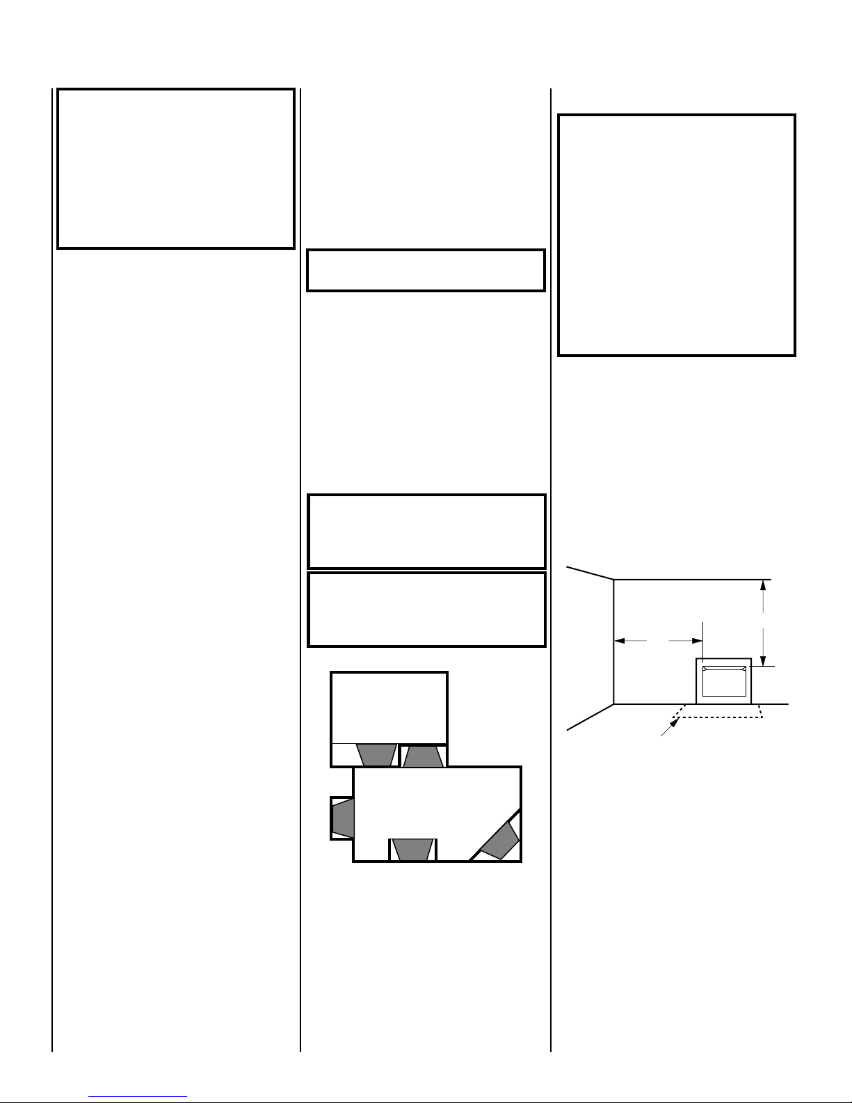
Ensure the minimum clearances shown in
ures 2 through 6
clearances are determined when facing the
front of the firebox.
Follow these instructions carefully to ensure
safe installation. Failure to follow these requirements may create a fire hazard.
Step 1. Sidewall clearances: The sides of the
firebox opening must be at least 16" from any
combustible wall (
are maintained. Left and right
Figure 2
16"
).
Fig-
42"
• Clearance to side wall, ceiling, woodwork
and windows.
• Location must not be affected by drafts
caused by kitchen exhaust fans, return air registers for forced air furnaces/air conditioners,
windows or doors.
• Installation must provide adequate ventilation and combustion air.
• Do not install this firebox in a sleeping room
or bathroom.
4
Not to Scale
Figure 1
NOTE: DIAGRAMS & ILLUSTRATION NOT TO SCALE.
Optional
Hearth Extension
Figure 2
Step 2. Ceiling clearance: The ceiling must be
at least 42" from the top of the firebox opening
(
Figure 2
Step 3. Noncombustible material (minimum
requirements) without wood mantel or other
combustible projections: To install the firebox
without wood mantel, shelf or other combustible projection above firebox opening, at least
8" of noncombustible material must be installed above the fireboxes described in this
manual (
).
Figure 3
).
Page 5

Noncombustible materials, such as slate and
marble, must be at least ¹⁄₂" thick.
8" or more of
Noncombustible
Material
Canopy
Heater in Firebox
Figure 3
Step 4. Noncombustible material (minimum
requirements) with wood mantel or other combustible projections: To install the firebox with
a wood mantel, shelf or other combustible
projection above firebox opening, at least 9" of
noncombustible material must be installed
above the fireboxes described in this manual
(
Figure 4
).
Example: The bottom of the mantel may project
from the wall a maximum of 2
¹⁄₂
" at a minimum
of 9" above the opening. The top shelf of the
mantel may project a maximum of 6" at a
minimum of 14
Noncombustible
Material
¹⁄₂
" above the opening.
12"
10
8"
6"
2 ¹⁄₂"
14 ¹⁄₂"
9"
Min.
Canopy
26"
22 ¹⁄₂"
18 ⁵⁄₈"
Figure 4
WARNING: THE CANOPY HOOD MUST
BE IN PLACE TO BE IN COMPLIANCE
WITH THE CLEARANCES SPECIFIED IN
FIGURE 4
.
DO NOT REMOVE OR REPLACE CANOPY
WITH ANY CANOPY SUPPLIED WITH
THE UNVENTED ROOM HEATER
If your mantel profile is unsafe, you may either:
• Raise the mantel to an acceptable height, or
• Remove the mantel.
Step 5. Floor clearance: This firebox must be
installed at least 5" above any combustible
flooring material, such as carpeting or asphalt
tile, which is closer than 14" to the base of the
firebox (
Figure 5
).
Combustible
Material
5" Min.
Figure 5
The firebox may also be installed nearer to the
floor if a minimum of 14" of noncombustible
material such as slate or marble is installed
between the base of the firebox and the combustible flooring (
Figure 6
Can be less
than 5"
14" Min.
).
Combustible
Material
Figure 6
ASSEMBLY STEPS
Note: Illustrations shown in this manual reflect
“typical” installations with nominal dimensions
and are for design and framing reference only.
Actual installations may vary due to individual
design preferences. However, always maintain
minimum clearances to combustible materials
and do not violate any specific installation requirements. Refer to the Framing Specifications Figures on page 7.
The UVFCE system consist of three basic
“sub-systems”:
1. The Firebox
2. The Gas Line
3. The Canopy
Note: The following steps represent the normal
sequence of installation. Each installation is
unique, however, and might require a different
sequence.
Step 1. Position firebox prior to framing or into
prepared framing.
Step 2. Field wire main power supply to circulating models for fan kit. (Electrical connections
should only be performed by an experienced,
licensed/certified tradesman.)
Step 3. Plumb gas line. (Gas connections should
only be performed by an experienced, licensed/
certified tradesman.)
Step 4. Install unvented gas log room heater
per the instructions provided with the unvented
room heater.
Step 5. Complete finish wall material, surround
and optional hearth extension to your individual
taste.
INSTALLATION
Gas Line Installation
CAUTION: PLUMBING CONNECTIONS SHOULD
ONLY BE PERFORMED BY A QUALIFIED, LICENSED PLUMBER. MAIN GAS SUPPLY MUST
BE OFF WHEN PLUMBING GAS LINE TO FIREPLACE OR PERFORMING SERVICE.
Consult all local codes.
It is recommended that the ¹⁄₂" gas line enter
the right side of the firebox. Connect the gas
line before the firebox is enclosed in the finished wall. The gas knockout is determined by
a 1 ¹⁄₈" round indentation located at the bottom
and slightly off center in the side refractories.
THE KNOCK-OUT IS ALWAYS REMOVED
FROM INSIDE THE FIREBOX. If removal is
attempted from the outer wrapper, side-refractory damage may occur. With a mediumsized hammer, lightly tap the surface of the
indentation. The refractory material is very
thin in this area and is easily removed. Once a
small hole has been made, continue tapping
until you have reached sufficient diameter for
the gas line to fit through. The entire knockout
does not have to be removed. Remove insulation in the gas line channel.
Install only a ¹⁄₂" (1 ¹⁄₂" max.) inside diameter
approved gas line through the firebox wall for
connection to the unvented room heater inside
the firebox.
NOTE: DIAGRAMS & ILLUSTRATION NOT TO SCALE.
5
Page 6

Ensure that a sediment trap is installed in the
existing gas line, if not, install a sediment trap
upstream of the heater to prevent moisture
and contaminants from passing through trap
to the heater controls and burners. Failure to
do so could prevent the heater from operating
reliably.
An external regulator must be used on all
propane (L.P.G.) heaters, in addition to the
regulator fitted to the heater, to reduce the
supply tank pressure to 13" w.c. (maximum).
Any copper tubing used to supply propane
(L.P.G.) from the tank must be internally tinned.
For an easier connection to the Unvented Gas
Log Room Heaters, connection fittings have
been supplied with the firebox. Cut and flare
tubing to fit.
IMPORTANT: HOLD HEATER REGULATOR
WITH A WRENCH TO PREVENT MOVEMENT
WHEN CONNECTING TO INLET PIPING.
Check Gas Type: The gas supply must be the
same as stated on the heater’s rating plate. If
the gas supply is different, DO NOT INSTALL
the heater. Contact your dealer for the correct
model.
Usually, no special floor support is needed for
the firebox, however, to be certain:
1. Estimate the total weight of the firebox
system and surround materials such as marble,
brick, stone, etc., to be installed.
2. Measure the square footage of the floor
space to be occupied by the system and surrounds.
3. Note the floor construction, i.e. 2 x 6’s, 2 x
8’s or 2 x 10’s, single or double joists, type and
thickness of floor boards.
Regulator
5 ³⁄₄"
³⁄₈" Close Nipple
³⁄₈" x ³⁄₈" FPT
Angle Fitting
³⁄₈" Aluminum Tubing
(Flared 45° Both Ends)
³⁄₈" Flared Nut
(2) Required
³⁄₈" x ¹⁄₂" FPT
Angle Fitting
Top View
Regulator
1"
Front View
Figure 7
The heater gas inlet connection is ³⁄₈" NPT at the
regulator, made on the right side facing the
heater. If a left side gas line is required, the gas
line may be led under the rear of the heater to
end at the right hand side for connection to the
inlet. However, this method is not recommended.
WARNING: CONNECTING DIRECTLY TO
AN UNREGULATED PROPANE (L.P.G.)
TANK CAN CAUSE AN EXPLOSION.
IMPORTANT: RE-PACK INSULATION MATERIAL IN SQUARE HOLE AROUND GAS LINE,
INTERIOR AND EXTERIOR, TO SEAL.
Consult installation and operating instructions
for the model of unvented room heater to be
installed.
Checking Gas Connections: Test all gas joints
from the gas meter to the gas heater regulator
for leaks using soap and water solution after
completing connection. DO NOT USE AN OPEN
FLAME.
Firebox Framing
Construct firebox framing following
through 12
and the chart on page 8 for your
specific installation requirements. Refer to
Figure 8
on page 7 for firebox dimensions.
The firebox may be installed directly on a combustible floor or raised on a platform of an
appropriate height. Do not place firebox on
carpeting, vinyl or other soft floor coverings. It
may, however, be placed on flat wood, plywood, particle board or other hard surfaces. Be
sure firebox rests on a solid continuous floor or
platform with appropriate framing for support
and so that no cold air can enter room from
under the firebox.
The firebox may be positioned and then the
framing built around it, or the framing may be
constructed and the firebox positioned into the
opening.
Figures 9
4. Use this information and consult your local
building code to determine if you need additional support.
CAUTION: DO NOT BLOCK THE HEAT-CIRCULATING AIR INLETS AND OUTLETS ON THE
VFC AND VFCE MODELS. DOING SO MAY
CREATE A POTENTIAL FIRE HAZARD.
If you plan to raise the firebox, build the platform assembly then position firebox on top.
Secure the platform to the floor to prevent
possible shifting.
Firebox Installation
Note: The firebox must be installed giving full
consideration to the clearance and height requirements identified in this manual.
Step 1. Slide the firebox into prepared framing
or position firebox in its final position and
frame later.
Step 2. Refer to firebox and framing specifications on pages 7 and 8 for framing dimensions
and details. Framing header may be positioned
directly on the firebox top spacers.
IMPORTANT: UNDER NO CIRCUMSTANCES
SHALL THE FIREBOX TOP SPACERS BE REMOVED OR MODIFIED. THE HEADER MAY BE
IN DIRECT CONTACT WITH THE TOP SPACERS BUT MUST NOT BE SUPPORTED BY THEM
OR NOTCHED TO FIT AROUND THEM.
Step 3. Level the firebox by checking the top
edge of the firebox. Shim if necessary.
6
NOTE: DIAGRAMS & ILLUSTRATION NOT TO SCALE.
Page 7

FIREBOX SPECIFICATIONS
4 ¹⁄₄"
6 ¹⁄₂"
38 ³⁄₄"
21"
1 ¹⁄₂"
1 ⁵⁄₁₆"
40 = 38"
45 = 42 ³⁄₄"
40 = 40 ⁵⁄₈"
45 = 45 ³⁄₈"
UVFCE Front View
34 ¹⁄₂"
J Box
Cover
1 ⁵⁄₁₆"
34 ¹⁄₂"
8 ¹⁄₄"
3 ¹⁄₂"
7"
3"
34 ¹⁄₂"
Gas Line
Knockout
8 ¹⁄₂"
38 ³⁄₄"
Figure 8
21 ¹⁄₂"
Left Side View
21 ¹⁄₂"
40 = 29 ¹⁄₈"
45 = 33 ³⁄₄"
40 = 40 ⁵⁄₈"
45 = 45 ³⁄₈"
Top View
NOTE: DIAGRAMS & ILLUSTRATION NOT TO SCALE.
21 ¹⁄₂"
Right Side View
7
Page 8

FRAMING SPECIFICATIONS
Header
Figure 9
Figure 10
J
Corner Installation
B
A
Back Wall Of Chase/Enclosure
Including Finishing Materials
D
C
A
E
If Any
G
Rough
Framing Face
(Unfinished Shown)
Framing Dimensions
Opening 40" 45"
A 40 ³⁄₄" 45 ¹⁄₂"
B 39" 39"
C 29" 33 ³⁄₄"
D 14 ¹⁄₂" 16 ⁷⁄₈"
E 71 ³⁄₄" 76 ¹⁄₂"
F 35 ⁷⁄₈" 38 ¹⁄₄"
G 21 ³⁄₈" 21 ³⁄₈"
F
H8"8"
J 50 ³⁄₄" 54"
Rough Framing Face
(Unfinished Shown)
Back Wall Of Chase/Enclosure
Including Finishing Materials
C
A
Figure 11
8
If Any
G
NOTE: DIAGRAMS & ILLUSTRATION NOT TO SCALE.
Figure 12
C
Rough Framing Face
(Unfinished Shown)
A
Back Wall Of Chase/Enclosure
Including Finishing Materials
If Any
G
HH
Page 9

3 Screws for 40" Models
4 Screws for 45" Models
Canopy
Firebox
Opening
Step 4. Firebox may be anchored to floor. Bend
down four (4) anchor tabs located at the base of
the firebox and secure to the floor by nailing
with 8d nails (
Figure 13
).
WARNING: DO NOT PACK OR FILL REQUIRED AIR SPACES WITH INSULATION
OR OTHER MATERIAL. NO MATERIAL IS
ALLOWED IN THESE AREAS (
AND 16
).
FIGURES 15
Canopy Installation
The factory-supplied canopy must be installed
on the firebox for safe operation. Refer to
Figure 17
.
Anchor Tab
Figure 13
Step 5. Firebox should be secured to side
framing members using nailing flanges. Use 8d
nails (
Figure 14
Nailling Flange
Framing Stud
).
8d Nail
Combustible
Wall
Figure 15
Combustible
Wall
¹⁄₂" Space
¹⁄₂" Space
Platform
Maintain
¹⁄₂" Air Space
at Back
and Sides
Maintain
¹⁄₂" Air Space
at Back
and Sides
Optional
Hearth
Extension
Floor
Figure 17
Step 1. Remove the screws from the top front
frame assembly. There are three (3) screws on
the 40" models and four (4) screws on the 45"
models. Also remove the two (2) top screws on
the side frames.
Step 2. Align the canopy with the holes in the
top frame.
Step 3. Replace the screws previously removed.
Step 4. Tighten side screws. Make sure the
canopy is level and secure.
Figure 14
Note: The nailing flange and the area directly
behind the nailing flange is exempt from the
clearances described on the firebox clearance
label.
Figure 16
Step 6. The canopy must be installed for safe
operation of the heater.
NOTE: DIAGRAMS & ILLUSTRATION NOT TO SCALE.
OPTIONAL EQUIPMENT
Adjustable Canopy
The optional canopies are designed for use on
masonry and other wood-burning fireplaces,
but may also be used on these built-in unvented fireboxes when a brass or larger canopy
is desired for aesthetic reasons. Models ACSPB and AC-BK are designed for use with
UVFCE unvented fireboxes. Refer to the installation instructions provided with the canopy
for installation details.
9
Page 10

Trim Kits
FIREBOX FINISHES
ACCESSORIES AND COMPONENTS
The UVFCE fireboxes can be enhanced with
stylish trim kits, Models 40 HTK-SPB and
45HTK-SPB. Refer to the installation instructions provided with the trim kits for installation
details.
Forced Air Kit
If you are installing the forced air kit, Model
FAB-1600, see the installation instructions provided with the kit for electrical wiring requirements (
Figure 18
nected to main power supply at time of installation if a forced air kit is to be installed later.
The electrical connections must be made before the firebox is framed and enclosed in the
finished walls.
This appliance must be electrically grounded in
accordance with local codes or, in the absence
of local codes, the national electrical code,
ANSI/NFPA 70 - (Latest Edition).
CAUTION: ELECTRICAL CONNECTIONS
SHOULD ONLY BE PERFORMED BY A QUALIFIED, LICENSED ELECTRICIAN. MAIN POWER
MUST BE OFF WHEN CONNECTING TO MAIN
ELECTRICAL POWER SUPPLY OR PERFORMING SERVICE.
). The firebox must be con-
Blower Motor
There are a wide variety of “finished looks” for
your UVFCE built-in unvented fireboxes from
formal wall decor with elaborate mantels to
rustic wood paneling or warm brick facings.
Only noncombustible materials like marble,
stone, tile, brick, etc. may overlap the black
front facing but be sure not to block the upper
or lower grilles. Seal all joints between the
black facing and wall surrounds to prevent air
intrusion. Use noncombustible caulking material only to seal the black metal facing to the
surround material on the finished wall.
REPLACEMENT PARTS
An exploded view of the firebox with numbered parts and a replacement parts list can be
found on page 11. Normally, all parts should
be ordered through your distributor or dealer.
Parts will be shipped at prevailing prices at
time of order.
When ordering repair parts, always give the
following information:
1. The model number of the firebox.
2. The serial number of the firebox.
3. The part number.
4. The description of the part.
5. The quantity required.
6. The installation date of the firebox.
Adjustable Canopy Black AC-BK
Brass AC-SPB
40HTK-SPB
Horizontal Trim Kits 45HTK-SPB
Grounded
to Appliance
120V
Appliance Junction Box
NOTE: If any of the original wire as supplied
must be replaced, it must be replaced with type
AWM 105°c – 18Ga. wire
Figure 18
Motor Plug
Receptacle
If you encounter any problems or have any
questions concerning the installation of a unvented heater in this system, please contact
your distributor. For the name of your nearest
distributor contact:
Lennox Hearth Products
1110 West Taft Avenue
Orange, California 92865
Forced Air Kit
(Includes Variable
Speed Wall Switch) FAB-1600
10
NOTE: DIAGRAMS & ILLUSTRATION NOT TO SCALE.
Page 11

4
2
1
7
8
6
9
3
5
REPLACEMENT PARTS LIST
UVFCE-40 UVFCE-45
No. Description Part No. Part No.
1. Side Refractory, Right 026042 026042
2. Side Refractory, Left 026041 026041
3. Bottom Refractory 044991 044992
4. Rear Refractory 026021 026022
5. Screen Panel 099648 099649
6. Screen Rod (2) 011382 010234
7. Canopy 054291 054300
8. Gas Line, ³⁄₈" 096908 096908
9. Nipple, ³⁄₈" 000802 000802
NOTE: DIAGRAMS & ILLUSTRATION NOT TO SCALE.
11
Page 12

Unvented Gas Room Heater
Limited Warranty 1 Year
THE WARRANTY
Lennox Hearth Products (LHP) warrants this Unvented Gas Room Heater to be free from defects in materials and workmanship at the time of manufacture.
REMEDY AND EXCLUSIONS
The coverage of this Warranty is limited to all components of the Unvented Gas Room Heater supplied by LHP.
This Warranty only covers LHP Unvented Gas Room Heaters installed in the United States or Canada.
If the Unvented Gas Room Heater covered by this Warranty is found to be defective within one year from the date of installation (see LHP’s right of investigation outlined below), LHP
will, at its option, replace or repair defective components of the Unvented Gas Room Heater supplied by LHP at no charge and will also pay for reasonable labor costs incurred in replacing
or repairing such components. If repair or replacement is not commercially practical, LHP will, at its option, refund the purchase price of the LHP Unvented Gas Room Heater.
This Warranty covers only parts and labor as provided above. In no case shall LHP be responsible for materials, components, or construction which are not manufactured or supplied
by LHP, or for the labor necessary to install, repair, or remove such materials, components or construction. All replacement or repair components will be shipped F.O.B. the nearest
Superior Fireplace Company factory.
QUALIFICATIONS TO THE WARRANTY
The Unvented Gas Room Heater Warranty outlined above is further subject to the following qualifications:
(1) The Unvented Gas Room Heater must be installed in accordance with LHP installation instructions and local building codes. The Warranty on this LHP Unvented Gas Room Heater
covers only the component parts supplied by LHP. The use of components manufactured by others with this LHP Unvented Gas Room Heater could create serious safety hazards,
may result in the denial of certification by recognized national safety agencies, and could be in violation of local building codes. This Warranty does not cover any damages occurring
from the use of any components not manufactured or supplied by LHP.
(2) The LHP Unvented Gas Room Heater must be subjected to normal use. The Unvented Gas Room Heaters are designed to burn either natural or propane gas only. Burning conventional
fireplace fuels such as wood, coal, or any other solid fuel will cause damage to the Unvented Gas Room Heater, will produce unsafe levels of carbon monoxide and will result in
a fire hazard.
LIMITATION ON LIABILITY
It is expressly agreed and understood that LHP’s sole obligation and purchaser’s exclusive remedy under this warranty, under any other warranty, expressed or implied, or in
contract, tort or otherwise, shall be limited to replacement, repair, or refund, as specified above.
In no event shall LHP be responsible for any incidental or consequential damages caused by defects in its products, whether such damage occurs or is discovered before or after
replacement or repair, and whether or not such damage is caused by LHP’s negligence. Some states do not allow the exclusion or limitation of incidental or consequential
damages, so the above limitation or exclusion may not apply to you. The duration of any implied warranty with respect to this LHP Unvented Gas Room Heater is limited to the
duration of the foregoing warranty. Some states do not allow limitations on how long an implied warranty lasts, so the above may not apply to you.
INVESTIGATION OF CLAIMS AGAINST WARRANTY
LHP reserves the right to investigate any and all claims against this Warranty and to decide upon method of settlement.
LHP NOT RESPONSIBLE FOR WORK DONE WITHOUT WRITTEN CONSENT
LHP shall in no event be responsible for any warranty work done without first obtaining LHP’s written consent.
DEALERS HAVE NO AUTHORITY TO ALTER THIS WARRANTY
LHP’s employees and dealers have no authority to make any warranties nor to authorize any remedies in addition to or inconsistent with those stated above.
HOW TO REGISTER A CLAIM AGAINST WARRANTY
In order for any claim under this Warranty to be valid, LHP must be notified of the claimed defect in writing to LHP, attention Customer Service Department, 1110 West Taft Avenue,
Orange, California 92865, as soon as reasonably possible after the defect is discovered. Claims against this Warranty in writing should include the date of installation, product
serial number and a description of the defect.
OTHER RIGHTS
This Warranty gives you specific legal rights, and you may also have other rights which vary from state to state.
LHP reserves the right to make changes at any time, without notice, in design, materials, specifications, prices and also to discontinue colors, styles and products.
Consult your local distributor for fireplace code information.
Printed in U.S.A. © 1998 by LHP
P/N 903761 REV. E 02/2004
LHP
1110 West Taft Avenue
Orange, CA 92865
 Loading...