

Page 1
UVFC-600
INSTALLATION
INSTRUCTIONS
STANDARD SERIES
36" & 42" Unvented Fireboxes
P/N 700,018M REV. C 12/2003
MODELS
UVFR-500 UVFC-500
UVFR-600 UVFC-600
UVFR-500
RETAIN THESE INSTRUCTIONS
FOR FUTURE REFERENCE
WARNING: IF THE INFORMATION IN THIS MANUAL
IS NOT FOLLOWED EXACTLY, A FIRE OR EXPLOSION MAY RESULT CAUSING PROPERTY DAMAGE,
PERSONAL INJURY OR LOSS OF LIFE.
FOR YOUR SAFETY: Do not store or use gasoline
or other flammable vapors or liquids in the vicinity
of this or any other appliance.
FOR YOUR SAFETY: What to do if you smell gas:
• DO NOT light any appliance.
• DO NOT touch any electrical switches.
• DO NOT use any phone in your building.
• Immediately call your gas supplier from a
neighbor’s phone.
Follow your gas suppliers instructions.
• If your gas supplier cannot be reached, call the
fire department.
Installation and service must be performed by a
qualified installer, service agency or the gas supplier.
NOTE: DIAGRAMS & ILLUSTRATION NOT TO SCALE.
FOR USE ONLY WITH DECORATIVE TYPE UNVENTED ROOM
HEATERS.
DO NOT BUILD A WOOD FIRE.
WARNING: IMPROPER INSTALLATION, ADJUSTMENT, ALTERATION, SERVICE OR MAINTENANCE CAN CAUSE INJURY OR PROPERTY DAMAGE. REFER TO THIS MANUAL.
FOR ASSISTANCE OR ADDITIONAL INFORMATION CONSULT A QUALIFIED INSTALLER, SERVICE AGENCY OR THE
GAS SUPPLIER.
WARNING: DO NOT BURN WOOD OR OTHER MATERIAL IN
THESE APPLIANCES.
CAREFULLY REVIEW THE INSTRUCTIONS SUPPLIED WITH
THE DECORATIVE TYPE UNVENTED ROOM HEATER FOR
THE MINIMUM FIREPLACE SIZE REQUIREMENT.
DO NOT INSTALL THE APPLIANCE IN THIS FIREBOX, UNLESS THIS FIREBOX MEETS THE MINIMUM DIMENSIONS
REQUIRED FOR THE INSTALLATIONS.
This is an unvented gas-fired heater. It uses air
(oxygen) from the room in which it is installed.
Provisions for adequate combustion and ventilation air must be provided. Refer to Combustion
and Ventilation Air Section, Page 3.
Due to high temperatures, the appliance should be located out
of traffic and away from furniture or draperies.
Do not place clothing or other materials on or near this appliance.
IMPORTANT: READ AND UNDERSTAND THESE INSTRUCTIONS
COMPLETELY BEFORE INSTALLING YOUR UNVENTED ROOM
HEATERS.
1
Page 2
TABLE OF CONTENTS
Firebox/Log Set Reference Chart ..... page 2
General Information......................... page 2
Inventory ......................................... page 2
Tools/Building Supplies ................... page 2
Important Safety Information .......... page 2
Codes .............................................. page 3
Combustion and Ventilation Air ....... page 3
Location of firebox........................... page 4
Clearances ....................................... page 4
Assembly Steps ...............................page 5
Gas Line Installation ........................ page 5
Firebox Framing............................... page 6
UVF-500 Specifications ................... page 6
Firebox Installation .......................... page 7
UVF-600 Specifications ................... page 7
Framing Specifications .................... page 8
Canopy Installation .......................... page 9
Optional Equipment ......................... page 9
Firebox finishes ............................... page 10
Replacement Parts .......................... page 10
Accessories/Components ................ page 10
Replacement Parts List.................... page 11
GENERAL INFORMATION
These ventless firebox enclosures are designed
to accept all ANSI Z21.11.2 approved Decorative Type Unvented Gas Log Room Heaters.
For the appropriate Unvented Gas Log Room
Heater model, refer to the chart below. Refer to
the installation instructions provided with the
log sets for detailed instructions.
The UVFC Series are unvented fireboxes. They
feature a self-contained heat-circulating system.
The UVFR Series is a conventional radiantheat unvented firebox.
This installation manual will enable you to
obtain a safe, efficient and dependable installation of your room heater system.
Do not alter or modify the firebox or its components under any circumstances. Any modification or alteration of the firebox system, including but not limited to the firebox and accessories, may void the warranty, listings and
approvals of this system and could result in an
unsafe and potentially dangerous installation.
These Built-In Unvented Fireboxes have been
tested and approved as Ventless Firebox Enclosures for Gas-Fired Decorative Type Ventless
Room Heaters to IAS 2-97.
WARNING: THESE BUILT-IN UNVENTED FIREBOXES HAVE ONLY
BEEN TESTED AND APPROVED FOR
USE WITH ANSI Z21.11.2 UNVENTED GAS LOGS.
Check the inventory list to be sure that you have
all the necessary parts in usable condition. Also
check for concealed damage.
Inventory
Unvented Gas Firebox
Canopy
Gas Connector Fittings
Installation and Operating Instructions
Tools and Building Supplies
Normally Required
Tools Should Include:
Phillips screwdriver
Hammer
Saw and/or sabersaw
Level
Measuring tape
Electric drill and bits
Pliers
Square
Piping complying with local codes
Pipe wrench
Tee joint
Pipe compound
Building Supplies Should Include:
Framing materials
Wall finishing materials
Caulking materials (noncombustible)
Fireplace surround materials
(noncombustible)
IMPORTANT SAFETY INFORMATION
INSTALLER: PLEASE LEAVE THESE INSTRUCTIONS WITH THE OWNER.
DO NOT ATTEMPT TO BURN SOLID
WOOD FUELS, OTHER GAS LOG SETS
OR ANY OTHER COMBUSTIBLE MATERIALS IN THIS UNVENTED FIREBOX.
Log Set Sizing Reference Chart
Unvented Firebox Unvented Room Heater Log Set
Model Natural Propane (L.P.G)
UVFC-500 VFGL-18/24MN/VN-3 VFGL-18/24MP/VP-3
PVFGL-18MN/VN PVFGL-18MP/VP
OWNER: PLEASE RETAIN THESE INSTRUCTION FOR FUTURE REFERENCE
IMPORTANT: BEFORE STARTING YOUR FIREBOX INSTALLATION, READ THESE INSTALLATION INSTRUCTIONS CAREFULLY TO BE SURE
YOU UNDERSTAND THEM COMPLETELY AND
IN ENTIRETY. FAILURE TO FOLLOW THESE
INSTRUCTIONS COULD CAUSE A HEATER
MALFUNCTION RESULTING IN SERIOUS INJURY AND/OR PROPERTY DAMAGE.
WARNING: ANY CHANGE TO THIS UNVENTED ROOM HEATER CAN BE DAN-
UVFC-600 VFGL-24/28MN/VN-3 VFGL-24/28MP/VP-3
PVFGL-24MN/VN PVFGL-24MP/VP
UVFR-500 VFGL-18/24MN/VN-3 VFGL-18/24MP/VP-3
PVFGL-18MN/VN PVFGL-18MP/VP
UVFR-600 VFGL-24/28MN/VN-3 VFGL-24/28MP/VP-3
PVFGL-24MN/VN PVFGL-24MP/VP
2
NOTE: DIAGRAMS & ILLUSTRATION NOT TO SCALE.
GEROUS. IMPROPER INSTALLATION OR
USE OF THIS HEATER CAN CAUSE SERIOUS INJURY OR DEATH FROM FIRE,
BURNS, EXPLOSION OR CARBON MONOXIDE POISONING.
Page 3

Carbon Monoxide Poisoning: Early signs of
carbon monoxide poisoning are similar to the
flu with headaches, dizziness and/or nausea.
If you have these signs, obtain fresh air immediately. Have the Unvented Gas Heater
serviced as it may not be operating correctly.
• Due to high temperatures, the firebox should
be located out of traffic and away from furniture
and draperies.
• Children and adults should be alerted to the
hazard of high surface temperature and should
stay away to avoid burns or clothing ignition.
• Young children should be carefully supervised when they are in the same room with the
heater.
• Do not place clothing or other flammable
material on or near the heater.
• Any safety screen or guard removed for
servicing the firebox must be replaced and/or
closed prior to operating the heater.
• Installation and repair should be done by a
qualified service person. The heater should be
inspected before use and at least annually by
a professional service person. More frequent
cleaning may be required due to excessive lint
from carpeting, bedding material, etc. It is
important that control compartments, burners
and circulating air passageways of the heater
be kept clean.
• Allow the heater to cool before servicing.
Always shut off any electricity or gas to the
heater while performing service work.
• Do not install the firebox in a sleeping room
or bathroom.
• The appliance and its individual shut-off valve
must be disconnected from the gas supply
piping system while performing any tests of the
gas supply piping system at pressures in excess of ¹⁄₂ psig.
• The heater must be isolated from the gas
supply piping system by closing its individual
manual shut-off valve during any pressure testing of the gas supply piping system at test
pressures equal to or less than ¹⁄₂ psig.
• Keep heater area clear and free from combustible materials, gasoline and other flammable vapors and liquids.
• Do not use this heater if any part has been
under water. Immediately call a qualified service technician to inspect the heater and to
replace any part of the control system and any
gas control which has been under water.
• Ensure that the heater is clean when operating. Excessive dust accumulation on the burner
and logs will increase the amount of carbon
monoxide formation and could lead to carbon
monoxide poisoning and death.
CODES
Adhere to all local codes or in their absence the
latest edition of The National Fuel Gas Code
ANSI Z223.1 or NFPA54 which can be obtained
from The American National Standards Institute, Inc. (1430 Broadway, New York, NY,
10018) or National Fire Protection Association,
Inc. (Batterymarch Park, Quincy, MA, 02269).
COMBUSTION AND VENTILATION AIR
Heaters installed in these appliances shall not
be installed in a confined space. Heaters
installed in these appliances may be located
in unusually tight construction provided the
space is unconfined, or if confined, is provided with two permanent openings communicating directly with an additional room(s)
of sufficient volume so that the combined
volume of all connected spaces meets the
criteria for an unconfined space, (National
Fuel Gas Code ANSI Z223.1 1992, Section
5.3). Generally 50 ft3 per 1,000 BTU input of
all operating appliances in the space.
The National Fuel Gas Code defines a confined
space as a space whose volume is less than
50 ft3 per 1,000 BTU/Hr (4.8 m3 per kw) of the
aggregate input rating of all appliances installed in that space and an unconfined space
as a space whose volume is not less than 50 ft
per 1,000 BTU/Hr (4.8 m3 per kw) of the aggregate input rating of all appliances installed in
that space. Rooms communicating directly with
the space in which the appliances are installed,
through openings not furnished with doors, are
considered a part of the unconfined space.
Unusually tight construction is defined as construction where:
a. wall and ceilings exposed to the outside
atmosphere have a continuous water vapor
retarder with a rating or one perm or less with
openings gasketed or sealed, and
b. weather stripping has been added on operable windows and doors, and
c. caulking or sealants are applied to areas such
as joints around window and door frames,
between sole plates and floors, between wallceiling joints, between wall panels, at penetrations for plumbing, electrical, and gas lines,
and at other openings.
Use the following equations to determine if
you have a confined or unconfined space.
1.Determine the volume of space — ft
Length x Width x Height = _____ ft
(Include adjoining rooms with doorless passageways or ventilation grills between
rooms.)
Example: 24' (L) x 16' (W) x 8' (H) = 3072
3
ft
2.Divide the volume of space by 50 ft3 to
determine the maximum BTU/Hr the space
can support.
______ (volume of space – ft
(Maximum BTU/Hr the space can support)
Example: 3072 ft
3
/ 50 ft3 = 61.44
or 61,440 BTU/Hr the space can support.
3.Add the BTU/Hr of all the fuel burning appli-
ances in the space.
Vent-Free heater _______ BTU/Hr
Gas appliance #1* _______ BTU/Hr
Gas appliance #2 + _______ BTU/Hr
Total = _______ BTU/Hr
Example:
Vent-free heater 26,000 BTU/Hr
Gas appliance #1 40,000 BTU/Hr
(water heater)
Total = 66,000 BTU/Hr
3
* Do not include direct-vent gas appliances.
Direct-vent is sealed combustion and draws
combustion air from the outdoors.
4. Compare the maximum BTU/Hr the space
can support with the actual amount of BTU/
Hr used.
_________ BTU/Hr
(max. the space can support)
_________ BTU/Hr
(actual amount of BTU/Hr used)
Example:
61,440 BTU/Hr
(max. the space can support)
66,000 BTU/Hr
(actual amount of BTU/Hr used)
The space in the above example is a confined
space because the actual BTU/Hr used is more
than the maximum BTU/Hr the space can support. You must provide additional fresh air.
3
.
3
)/ 50 ft3 =
3
NOTE: DIAGRAMS & ILLUSTRATION NOT TO SCALE.
3
Page 4
WARNING: IF THE AREA IN WHICH THE
HEATER MAY BE OPERATED IS SMALLER
THAN THAT DEFINED AS AN UNCONFINED SPACE, PROVIDE ADEQUATE
COMBUSTION AND VENTILATION AIR BY
ONE OF THE METHODS DESCRIBED IN
THE NATIONAL FUEL GAS CODE, ANSI
Z223.1 1992, SECTION 5.3 OR APPLICABLE LOCAL CODES.
Your options are:
a. Rework equations adding the space of ad-
joining room(s). If the extra volume provides
an unconfined space, then remove door or
add ventilation grills between rooms. Refer
to National Fuel Gas Code, ANSI Z223.1
1992, Section 5.3.
b. Vent room directly to the outdoors. Refer to
National Fuel Gas Code, ANSI Z223.1 1992,
Section 5.3.
c. Install a lower BTU/Hr heater, such as a
21,000 BTU/Hr, to make the area an unconfined space.
If the actual BTU/Hr used is less than the
maximum BTU/Hr the space can support, then
the space is an unconfined space. You will need
no additional fresh air ventilation for an unconfined space.
• Never obstruct the front opening of the unvented firebox or restrict the flow of combustion and ventilation air.
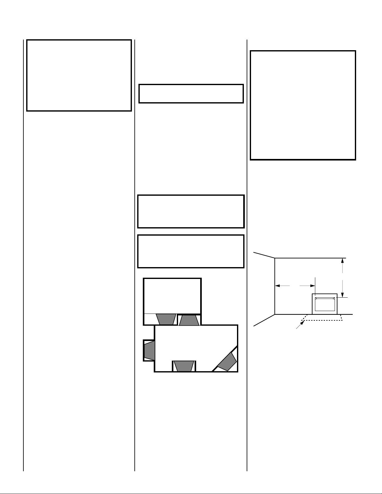
• Minimize modifications to existing construction. See
Figure 1
for location suggestions.
WARNING: MAINTAIN MINIMUM
CLEARANCES.
Do not install in the vicinity where gasoline or
other flammable liquids may be stored. The
unvented firebox must be kept clear and free
from these combustible materials.
CAUTION: HEATERS CREATE WARM AIR CURRENTS. THESE CURRENTS MOVE HEAT TO
WALL SURFACES NEXT TO HEATER. INSTALLING HEATER NEXT TO VINYL OR CLOTH WALL
COVERINGS OR OPERATING HEATER WHERE
IMPURITIES IN THE AIR (SUCH AS TOBACCO
SMOKE) EXISTS, MAY DISCOLOR WALLS.
WARNING: DO NOT ALLOW FANS TO
BLOW DIRECTLY INTO THE FIREPLACE.
AVOID ANY DRAFTS THAT ALTER
BURNER FLAME PATTERNS.
WARNING: DO NOT USE A BLOWER INSERT, HEAT EXCHANGER INSERT OR
OTHER ACCESSORY NOT APPROVED
FOR USE WITH THIS FIREPLACE.
Clearances
WARNING: DO NOT INSTALL THESE
BUILT-IN UNVENTED FIREBOXES IN
SLEEPING QUARTERS, OR IN RECREATIONAL VEHICLES.
WARNING: DO NOT INSTALL THESE
APPLIANCES:
• WHERE CURTAINS, FURNITURE,
CLOTHING OR OTHER FLAMMABLE
OBJECTS ARE LESS THAN 42" FROM
THE FRONT OF THE UNVENTED ROOM
HEATER.
• IN HIGH TRAFFIC AREAS.
• IN WINDY OR DRAFTY AREAS.
Ensure the minimum clearances shown in
ures 2 and 3
clearances are determined when facing the
front of the firebox.
Follow these instructions carefully to ensure
safe installation. Failure to follow these requirements may create a fire hazard.
Sidewall clearances: The sides of the firebox
opening must be at least 16" from any combustible wall (
are maintained. Left and right
Figure 2
).
Fig-
LOCATION OF FIREBOX
Carefully select the best location for installation
of your built-in unvented firebox. The following
factors should be taken into consideration:
• Clearance to side wall, ceiling, woodwork
and windows.
• Location must not be affected by drafts
caused by kitchen exhaust fans, return air registers for forced air furnaces/air conditioners,
windows or doors.
• Installation must provide adequate ventilation and combustion air.
• Do not install this firebox in a sleeping room
or bathroom.
• Location should be out of high traffic areas
and away from furniture and draperies due to
heat from firebox.
Figure 1
Not to Scale
40"
16"
Optional
Hearth Extension
Figure 2
Ceiling clearance: The ceiling must be at
least 40" from the top of the firebox opening
(
Figure 2
Noncombustible material: Noncombustible
materials, such as slate and marble, must be at
least ¹⁄₂" thick and may be used without restric-
tion above the firebox opening, to the sides or
as a hearth extension, so long as they do not
obstruct vent openings for heat circulating
models.
).
4
NOTE: DIAGRAMS & ILLUSTRATION NOT TO SCALE.
Page 5

Safe
Combustible
Mantel
and Trim
Zone
18"
Min.
Canopy
8"
Max.
9"
Min.
Fireplace
Opening
Finished
Wall
3"
Header
Spacer
Figure 3
Noncombustible material (minimum requirements) with wood mantel or other
combustible projections: To install the fire-
box with a wood mantel, shelf or other combustible projection above firebox opening.
Refer to
Figure 3
.
WARNING: THE CANOPY HOOD MUST
BE IN PLACE TO BE IN COMPLIANCE
WITH THE CLEARANCES SPECIFIED IN
FIGURE 3
. DO NOT REMOVE OR REPLACE CANOPY, ONLY USE CANOPY
SUPPLIED WITH THE FIREBOX. DO
NOT USE ANY CANOPY WHICH MAY BE
PROVIDED WITH THE DECORATIVE TYPE
UNVENTED ROOM HEATER.
If your mantel profile is unsafe, you may either:
• Raise the mantel to an acceptable height, or
• Remove the mantel.
Floor clearance: These fireplaces may sit
directly on a combustible surface.
ASSEMBLY STEPS
Note: Illustrations shown in this manual re-
flect “typical” installations with nominal dimensions and are for design and framing
reference only. Actual installations may vary
due to individual design preferences. However, always maintain minimum clearances to
combustible materials and do not violate any
specific installation requirements. Refer to the
Framing Specifications Figures on page 8.
Note: The following steps represent the normal sequence of installation. Each installation
is unique, however, and might require a different sequence.
Step 1. Position firebox prior to framing or
into prepared framing.
Step 2. Field wire main power supply to circulating models for fan kit. (Electrical connections should only be performed by an experienced, licensed/certified tradesman.)
Step 3. Plumb gas line. (Gas connections
should only be performed by an experienced,
licensed/certified tradesman.)
Step 4. Install decorative type unvented room
heater per the instructions provided with the
unvented room heater.
Step 5. Complete finish wall material, surround and optional hearth extension to your
individual taste.
INSTALLATION
Gas Line Installation
CAUTION: PLUMBING CONNECTIONS SHOULD
ONLY BE PERFORMED BY A QUALIFIED, LICENSED PLUMBER. MAIN GAS SUPPLY MUST
BE OFF WHEN PLUMBING GAS LINE TO FIREPLACE OR PERFORMING SERVICE.
Consult all local codes.
It is recommended that the ¹⁄₂" gas line enter
the side of the firebox. Connect the gas line
before the firebox is enclosed in the finished
wall. The gas knockout is determined by an
indentation located at the bottom and slightly
off center in the side refractories. THE KNOCK-
OUT IS ALWAYS REMOVED FROM INSIDE
THE FIREBOX. If removal is attempted from
the outer wrapper, side-refractory damage
may occur. With a medium-sized hammer,
lightly tap the surface of the indentation. The
refractory material is very thin in this area and
is easily removed. Once a small hole has been
made, continue tapping until you have reached
sufficient diameter for the gas line to fit
through. The entire knockout does not have
to be removed.
Install only a ¹⁄₂" (1 ¹⁄₂" max.) inside diameter
approved gas line through the firebox wall for
connection to the unvented room heater inside
the firebox.
Ensure that a sediment trap is installed in the
existing gas line, if not, install a sediment trap
upstream of the heater to prevent moisture and
contaminants from passing through trap to the
heater controls and burners. Failure to do so
could prevent the heater from operating reliably.
An external regulator must be used on all propane (L.P.G.) heaters, in addition to the regulator fitted to the heater, to reduce the supply tank
pressure to 13" w.c. (maximum). Any copper
tubing used to supply propane (L.P.G.) from
the tank must be internally tinned.
IMPORTANT: HOLD HEATER REGULATOR
WITH A WRENCH TO PREVENT MOVEMENT
WHEN CONNECTING TO INLET PIPING.
Check Gas Type: The gas supply must be the
same as stated on the heater’s rating plate. If
the gas supply is different, DO NOT INSTALL
the heater. Contact your dealer for the correct
model.
WARNING: CONNECTING DIRECTLY TO
AN UNREGULATED PROPANE (L.P.G.)
TANK CAN CAUSE AN EXPLOSION.
IMPORTANT: RE-PACK INSULATION MATERIAL IN SQUARE HOLE AROUND GAS LINE,
INTERIOR AND EXTERIOR, TO SEAL.
Consult installation and operating instructions
for the model of unvented room heater to be
installed.
Checking Gas Connections: Test all gas joints
from the gas meter to the gas heater regulator
for leaks using soap and water solution after
completing connection. DO NOT USE AN OPEN
FLAME.
NOTE: DIAGRAMS & ILLUSTRATION NOT TO SCALE.
5
Page 6

Firebox Framing
UVF-500 SPECIFICATIONS
Construct firebox framing following
through 8
and the chart on page 8 for your
Figures 6
specific installation requirements. Refer to
Figures 4 and 5
on pages 6 and 7 for firebox
dimensions.
The firebox may be installed directly on a combustible floor or raised on a platform of an
appropriate height. Do not place firebox on
carpeting, vinyl or other soft floor coverings. It
may, however, be placed on flat wood, plywood, particle board, metal or other hard surfaces which extend the full width and depth of
the enclosure. Be sure firebox rests on a solid
continuous floor or platform with appropriate
framing for support and so that no cold air can
enter room from under the firebox.
The firebox may be positioned and then the
framing built around it, or the framing may be
constructed and the firebox positioned into the
opening.
Usually, no special floor support is needed for
the firebox, however, to be certain:
1. Estimate the total weight of the firebox
system and surround materials such as marble,
brick, stone, etc., to be installed.
2. Measure the square footage of the floor
space to be occupied by the system and surrounds.
7 ¹⁄₂"
(191 mm)
27 ⁷⁄₈"
(708 mm)
Gas Line
Access
20 ³⁄₁₆"
(513 mm)
(940 mm)
42"
(1067 mm)
Front
Gas Line
Access
37"
36"
(914 mm)
40"
(1016 mm)
2"
(51 mm)
Fireplace Top Spacer
9 ³⁄₁₆"
(233 mm)
9 ¹⁄₁₆"
(230 mm)
9 ⁵⁄₈"
(244 mm)
7 ³⁄₁₆"
(183 mm)
(813 mm)
37"
(940 mm)
32"
(940 mm)
37"
3. Note the floor construction, i.e. 2 x 6’s, 2 x
8’s or 2 x 10’s, single or double joists, type and
thickness of floor boards.
4. Use this information and consult your local
building code to determine if you need additional support.
CAUTION: DO NOT BLOCK THE HEAT-CIRCULATING AIR INLETS AND OUTLETS ON THE
VFC AND VFCE MODELS. DOING SO MAY
CREATE A POTENTIAL FIRE HAZARD.
If you plan to raise the firebox, build the platform assembly then position firebox on top.
Secure the platform to the floor to prevent
possible shifting.
Figure 4
20 ¹⁄₄"
(514 mm)
Left Side
Fireplace
Top Spacer
1"
(25 mm)
Junction
27 ¹⁄₄"
(692 mm)
42"
(1067 mm)
Top View
Box
(1016 mm)
40"
19 ⁵⁄₈"
(498 mm)
Right Side
20 ¹⁄₄"
(514 mm)
6
NOTE: DIAGRAMS & ILLUSTRATION NOT TO SCALE.
Page 7

Firebox Installation
UVF-600 SPECIFICATIONS
Note: The firebox must be installed giving full
consideration to the clearance and height requirements identified in this manual.
Step 1. Slide the firebox into prepared framing
or position firebox in its final position and
frame later.
Step 2. Refer to firebox and framing specifications on pages 6, 7and 8
Figures 6 through 10
for framing dimensions and details. Framing
header may be positioned directly on the firebox top spacers.
Note: The framed depth from a framed wall,
must always be measured from a finished
surface. If a wall covering such as drywall is to
be attached to the rear wall, then the depth
must be measured from the drywall surface. It
is important that this dimension be exact.
IMPORTANT: UNDER NO CIRCUMSTANCES
SHALL THE FIREBOX TOP SPACERS BE REMOVED OR MODIFIED. THE HEADER MAY BE
IN DIRECT CONTACT WITH THE TOP SPACERS BUT MUST NOT BE SUPPORTED BY THEM
OR NOTCHED TO FIT AROUND THEM.
Step 3. Level the firebox by checking the top
edge of the firebox. Shim if necessary.
Step 4. Fireplace should be secured to side
framing members using the full length nailing
tabs at the top and bottom of the fireplace front
face. Use 8d nails (
see Figure 9
).
8 ³⁄₈"
(213 mm)
29 ⁵⁄₈"
(752 mm)
Gas Line
Access
22 ⁵⁄₁₆"
(566 mm)
(1143 mm)
45"
38"
(965 mm)
41"
(1041 mm)
(1194 mm)
Front
Gas Line
47"
Access
2"
(51 mm)
13 ³⁄₈"
(340 mm)
43"
(1092 mm)
7 ³⁄₁₆"
(183 mm)
Fireplace Top Spacer
9 ⁷⁄₈"
(251 mm)
10"
(254 mm)
Junction
Box
43"
(1092 mm)
20 ⁵⁄₈"
(524 mm)
Left Side
Fireplace
Top Spacer
1"
(25 mm)
Figure 5
NOTE: DIAGRAMS & ILLUSTRATION NOT TO SCALE.
31 ⁹⁄₁₆"
(802 mm)
47"
(1194 mm)
Top View
45"
(1143 mm)
21 ¹⁄₄"
(540 mm)
Right Side
(540 mm)
21 ¹⁄₄"
7
Page 8

FRAMING SPECIFICATIONS
B
Header
Framing Dimensions
Opening UVF-500 UVF-600
Figure 6
Figure 7
H
Corner Installation
A
Back Wall Of Chase/Enclosure
Including Finishing Materials
D
C
A
E
If Any
G
Rough
Framing Face
(Unfinished Shown)
A 41 ¹⁄₄" 46 ¹⁄₄"
B 37 ¹⁄₂" 43 ¹⁄₂"
C 27 ¹⁄₂" 31 ³⁄₄"
D 13 ³⁄₄" 15 ⁷⁄₈"
E 66 ³⁄₄" 73"
F 33 ³⁄₈" 36 ¹⁄₂"
G 19 ⁵⁄₈" 20 ⁵⁄₈"
F
H 47 ¹⁄₄" 51 ⁵⁄₈"
Rough Framing Face
(Unfinished Shown)
Figure 8
8
Back Wall Of Chase/Enclosure
Including Finishing Materials
C
A
If Any
G
NOTE: DIAGRAMS & ILLUSTRATION NOT TO SCALE.
Page 9

Step 2. Align the canopy with the holes in the
top frame.
Step 3. Replace the screws previously removed.
Blower Kit Installation
To install the blower kit, follow Steps 1 thru 5
and refer to
Figures 12, 13 and 14
.
8d Nail
Figure 9
Note: The nailing flange and the area directly
behind the nailing flange is exempt from the
clearances described on the firebox clearance
label.
Step 5. To safely operate the heater with consideration of the mantel clearances the canopy
must be installed.
Canopy Installation
The factory-supplied canopy must be installed
on the firebox for safe operation. See
Figure 10
Step 4. Tighten side screws. Make sure the
canopy is level and secure.
OPTIONAL EQUIPMENT
Blower Kit
Circulating Models Only
If you are installing one of the blower kits,
Models FBK-100 or FBK 200, follow Steps 1
through 5, and see the installation instructions
provided with the kit for electrical wiring requirements (
be connected to main power supply at time of
installation if a forced air kit is to be installed
later. The electrical connections must be made
before the firebox is framed and enclosed in the
finished walls.
This appliance must be electrically grounded in
accordance with local codes or, in the absence
of local codes, the national electrical code,
ANSI/NFPA 70 - (Latest Edition).
CAUTION: ELECTRICAL CONNECTIONS
SHOULD ONLY BE PERFORMED BY A QUALIFIED, LICENSED ELECTRICIAN. MAIN POWER
.
MUST BE OFF WHEN CONNECTING TO MAIN
ELECTRICAL POWER SUPPLY OR PERFORMING SERVICE.
see Figure 11 )
. The firebox must
Step 1. Locate the blower motor shield.
Step 2. Remove the motor shield by bending it
along the perforation until the tabs break away.
Step 3. With the motor shield removed, place
the blower in the unit with the power cord up
and slide to the back of the unit until the motor
is behind the rear support.
Step 4. Rotate the blower 90 degrees, so that
the discharge is up.
Step 5. Move left side of blower around until it
is in the proper position and bend the retaining
tabs in the bottom of the unit up into the slots
on the blower.
Blower Motor
Motor Shield
Figure 12
UVF-500
Shown
UVF-500
Canopies
Attaching
Screws
3 Screws for 500 Models
4 Screws for 600 Models
UVF-600
Canopies
Firebox
Opening
Firebox
Opening
Figure 10
Step 1. Remove the screws from the top front
frame assembly. There are three (3) screws on
the 500 models and four (4) screws on the 600
models.
Blower Motor
Grounded
to Appliance
120V
Appliance Junction Box
NOTE: If any of the original wire as supplied
must be replaced, it must be replaced with type
AWM 105°c – 18Ga. wire
Figure 11
NOTE: DIAGRAMS & ILLUSTRATION NOT TO SCALE.
Perforation
Tabs
Motor Plug
Motor Shield Removed
Receptacle
Figure 13
Rotated Blower In Final Position
Figure 14
9
Page 10

FIREBOX FINISHES
ACCESSORIES AND COMPONENTS
There are a wide variety of “finished looks” for
your built-in unvented firebox from formal wall
decor with elaborate mantels to rustic wood
paneling or warm brick facings.
Only noncombustible materials like marble,
stone, tile, brick, etc. may overlap the black
front facing but be sure not to block the upper
or lower grilles. Seal all joints between the black
facing and wall surrounds to prevent air intrusion. Use noncombustible caulking material
only to seal the black metal facing to the surround material on the finished wall.
REPLACEMENT PARTS
An exploded view of the firebox with numbered parts and a replacement parts list can be
found on page 11. Normally, all parts should
be ordered through your distributor or dealer.
Parts will be shipped at prevailing prices at
time of order.
When ordering repair parts, always give the
following information:
1. The model number of the firebox.
2. The serial number of the firebox.
3. The part number.
4. The description of the part.
5. The quantity required.
6. The installation date of the firebox.
If you encounter any problems or have any
questions concerning the installation of a unvented heater in this system, please contact
your distributor or dealer.
(FBK-200 Models Only)
Blower Kits
-Single Speed 80L84 FBK-100
-Variable Speed 80L85 FBK-200
Blower Kit
The FBK-100 blower provides for a constant
velocity forced air circulation feature for your
appliance. The FBK-200 assembly with variable speed wall switch provides a forced air
circulation feature for your appliance.
Decorative Volcanic Stone 80L42 FDVS
Decorative Volcanic Stone
The decorative volcanic stone, Model FDVS,
can be used to enhance the look of your appliance. Decorative volcanic stone is standard
with this appliance. Order model FDVS for
replacement of stone when needed. Spread the
decorative volcanic stone evenly around the
bottom of the firebox.
10
NOTE: DIAGRAMS & ILLUSTRATION NOT TO SCALE.
Page 11

REPLACEMENT PARTS
3
2
4
1
5
UVFR-600
3
4
6
5
UVFR-500
UVF-500 UVF-600
No. DESCRIPTION Part No. Qty. Part No. Qty.
Gas Fireplace Assembly – – – –
1. Firescreen 36L89 2 36L99 2
2. Rod, Screen 88L95 2 88L96 2
3. Refractory, Side 88L59 2 88L65 2
4. Refractory, Rear 88L58 1 88L64 1
5. Refractory Base 88L57 1 88L63 1
6. Canopy 96L27 1 96L28 1
NOTE: DIAGRAMS & ILLUSTRATION NOT TO SCALE.
11
Page 12

The manufacturer reserves the right to make changes at any time, without notice, in design, materials, specifications, prices and also to discontinue colors, styles and products.
Consult your local distributor for fireplace code information.
Printed in U.S.A. © 2000 by LHP
P/N 700,018M REV. C 12/2003
Manufactured By LHP
1110 West Taft Avenue • Orange, CA 92865
 Loading...