

Superior SSDVR-4035CNE, SSDVT-4035CNE, SSDVR-4035CNM, SSDVT-3530CNM, SSDVR-3530CNE User Manual [en, fr]
...Page 1
HOMEOWNER'S CARE AND
OPERATION INSTRUCTIONS
RETAIN THESE INSTRUCTIONS
FOR FUTURE REFERENCE
WARNINGS
• Hot! Do not touch! The glass and
surfaces of this appliance will be hot
during operation and will retain heat
for a while after shutting off the appliance. Severe burns may result.
• Carefully supervise children in the
same room as appliance.
If small children are present in the home, it is
•
recommended that this appliance be fi tted with
a screen door or screen panel kit. See Page 15
for ordering information.
WARNING: IF THE INFORMATION IN THIS MANUAL
IS NOT FOLLOWED EXACTLY, A FIRE OR EXPLOSION MAY RESULT CAUSING PROPERTY DAMAGE,
PERSONAL INJURY OR LOSS OF LIFE.
FOR YOUR SAFETY: Do not store or use gasoline
or other fl ammables or liquids in the vicinity of
this or any other appliance.
FOR YOUR SAFETY: What to do if you smell gas:
DIRECT VENT
SSDV-35/40 SERIES
DIRECT-VENT GAS FIREPLACE HEATERS
P/N 725,033M REV. D 05/2006
MODELS
Millivolt Models Electronic Models
SSDVT-3530CNM
SSDVR-3530CNM
SSDVT-4035CNM
SSDVR-4035CNM
A French manual is available upon request. Order P/N 725,033CF
Ce manuel d’installation est disponible en francais, simplement en
faire la demande. Numéro de la pièce 725,033CF
AVERTISSEMENT: ASSUREZ-VOUS DE BIEN
SUIVRE LES INSTRUCTIONS DONNÉ DANS CETTE
NOTICE POUR RÉDUIRE AU MINIMUM LE RISQUE
D'INCENDIE OU POUR ÉVITER TOUT DOMMAGE
MATÉRIEL, TOUTE BLESSURE OU LA MORT.
POUR VOTRE SÉCURITÉ: Ne pas entreposer ni
utiliser d'essence ni d'autre vapeurs ou liquides
infl ammables dans le voisinage de cet appareil ou
de tout autre appareil.
SSDVT-3530CNE
SSDVR-3530CNE
SSDVT-4035CNE
SSDVR-4035CNE
• DO NOT light any appliance.
• DO NOT touch any electrical switches.
• Do not use any phone in your building.
• Immediately call your gas supplier from a
neighbor’s phone. Follow your gas suppliers
instructions.
• If your gas supplier cannot be reached, call
the fi re department.
Installation and service must be performed by
a qualifi ed installer, service agency or the gas
supplier.
OTL Report No. 116-F-29-5
POUR VOTRE SÉCURITÉ: Que faire si vous sentez
une odeur de gaz:
• Ne pas tenter d'allumer d'appareil.
• Ne touchez à aucun interrupteur. Ne pas vous
servir des téléphones se trouvant dans le batiment où vous vous trouvez.
• Evacuez la piéce, le bâtiment ou la zone.
• Appelez immédiatement votre fournisseur de
gaz depuis un voisin. Suivez les instructions
du fournisseur.
• Si vous ne pouvez rejoindre le fournisseur de
gaz, appelez le service dos incendies.
L'installation et service doit être exécuté par un
qualifi é installeur, agence de service ou le fournisseur de gaz.
Page 2
SAFETY & WARNIING
INFORMATION
IMPORTANT: PLEASE READ THIS
MANUAL IN ITS ENTIRETY AND
UNDERSTAND THESE RULES TO
FOLLOW FOR SAFETY.
WARNING
If the information in this
manual is not followed
exactly, a fi re or explosion may result causing property damage,
personal injury or loss
of life.
WARNING
Improper installation, adjustment, alteration, service or
maintenance can cause injury
or property damage. Refer to
this manual. For assistance or
additional information consult
a qualified installer, service
agency or the gas supplier.
WARNING
Children and adults should be
alerted to the hazards of high
surface temperatures. Use
caution around the appliance
to avoid burns or clothing ignition. Young children should be
carefully supervised when they
are in the same room as the
appliance.
Note: An Optional Screen Panel
for the glass is available (see
Page 15 for ordering information).
WARNING
Do not place clothing or other
fl ammable materials on or near
this appliance.
AVERTISSEMENT
Surveiller les enfants. Garder les
vêtements, les meubles, l'essence
ou autres liquides à vapeur infl ammables à cote de l'appareil.
WARNING
Do not use these appliances if
any part has been under water.
Immediately call a qualifi ed,
professional service technician
to inspect the appliances and to
replace any parts of the control
system and any gas controls
which have been under water.
AVERTISSEMENT
Ne pas se servir de cet appareil
s'il a été plongé dans l'eau,
complètement ou en partie.
Appeler un technicien qualifi é
pour inspecter l'appareil et remplacer toute partie du système de
contrôle et toute commande qui
ont été plongés dans l'eau.
WARNING
Do not attempt to alter or modify
the construction of the appliance
or its components. Any modifi cation or alteration may void
the warranty, certifi cation and
listings of this unit.
WARNING
Failure to comply with the installation and operating instructions
provided in this document will
result in an improperly installed
and operating appliance, voiding
its warranty. Any change to this
appliance and/or its operating
controls is dangerous. Improper
installation or use of this appliance can cause serious injury or
death from fi re, burns, explosion
or carbon monoxide poisoning.
IMPORTANT
These appliances must not be
connected to a chimney or fl ue
serving a separate Solid-Fuel
burning appliance.
2
WARNING
Carbon monoxide poisoning:
early signs of carbon monoxide
poisoning are similar to the fl u
with headaches, dizziness and/or
nausea. If you have these signs,
obtain fresh air immediately.
Turn off the gas supply to the
appliance and have it serviced
by a qualifi ed professional, as it
may not be operating correctly.
WARNING
Any safety guard or screen
removed for servicing the appliance must be replaced prior to
operating the appliance.
NOTE: DIAGRAMS & ILLUSTRATIONS NOT TO SCALE.
WARNING
This appliance is only for use with
the type of gas indicated on rating
plate. This appliance is not convertible for use with other gases,
unless a certifi ed kit is used.
AVERTISSEMENT
Cet appareil doit être utilisé
uniquement avec les types de
gaz indiqués sur la plaque signalétique. Ne pas l'utiliser avec
d'autres gaz sauf si un kit de
conversion certifi é est installé.
WARNING
These fi replaces are vented heaters. Do not burn wood or other
material in these appliances.
Page 3
CONGRATULATIONS!
In selecting this SUPERIOR Direct-Vent Gas Appliance you have chosen the fi nest and
most dependable fi replace to be found anywhere. A beautiful, prestigious, alternative
to a wood burning fi replace. Welcome to a Family of tens of thousands of satisfi ed
SUPERIOR Fireplace Owners.
Please read and carefully follow all of the instructions found in this manual. Please pay
special attention to the safety instructions provided in this manual. The Homeowner's
Care and Operation Instructions included here will assure that you have many years of
dependable and enjoyable service from your SUPERIOR product.
TABLE OF CONTENTS
Safety & Warning Information ..........Page 2
Introduction ......................................Page 3
General Information ..........................Page 3
Gas Controls Access .........................Page 4
Operation / Care of Your Appliance ...Page 5
Variable Flame Adjustment ................Page 5
Maintenance ......................................Page 6
Front Glass Enclosure Panel,
Removal and Installation .................Page 7
Install Volcanic Stone,
Embers & Logs .................................Page 8
Burner Flame Appearance & Sooting Page 11
Burner Flame Adjustments ................Page 11
Millivolt Appliance Checkout .............Page 12
Electronic Appliance Checkout ..........Page 12
Wiring Diagrams ...............................Page 13
Warranty ...........................................Page 13
Product Reference Information .........Page 13
Accessory Components ....................Page 14
Lighting Instructions – Millivolt ........Page 17
Lighting Instructions – Electronic .....Page 19
Maintenance Schedule ......................Page 21
Troubleshooting Guide – Millivolt .....Page 22
Troubleshooting Guide – Electronic ..Page 22
Replacement Parts List .....................Page 24
INTRODUCTION
The Fireplace models covered in this manual
are Direct-Vent sealed combustion gas fi replace
heaters designed for residential application.
Direct-Vent appliances operate with the combustion chamber completely isolated from the
indoor environment. All air for combustion is
brought in from the outside and exhaust gases
are vented through the same direct vent, co-axial
(intake/exhaust) vent system.
The Millivolt appliances have a millivolt gas
control valve with piezo ignition system provides
safe, effi cient operation. If any optional accessories which require electrical power are being
installed, the electrical power must be provided
at the time of appliance installation.
The Electronic appliances have an electronic
intermittent pilot system provides safe, effi cient
operation. External electrical power is required
to operate these appliances.
These appliances comply with National Safety
Standards and are tested and listed by Omni-Test
Laboratories (Report No. 116-F-29-5) to ANSI
Z21.88b-2003 (in Canada, CSA-2.33b-2003),
and CAN/CGA-2.17-M91 in both USA and
Canada, as vented gas fi replace heaters.
The Installation must conform to local codes
or, in the absence of local codes, with the
National Fuel Gas Code, ANSI Z223.1/NFPA
54-latest edition, or the Natural Gas and
Propane Installation Code, CSA B149.1-latest
edition. The appliance, when installed, must
be electrically grounded in accordance with
local codes or, in the absence of local codes,
the latest edition of the National Electrical Code,
ANSI/NFPA 70, or the Canadian Electrical Code,
CSA C22.1 - latest editions.
GENERAL INFORMATION
Note: Installation and repair should be performed by a qualifi ed service person. The
appliance should be inspected annually by a
qualifi ed professional service technician. More
frequent inspections and cleanings may be
required due to excessive lint from carpeting,
bedding material, etc.
It is imperative that the control compartment,
burners and circulating air passage ways of
appliance be kept clean.
S'assurer que le brùleur et le compartiment des
commandes sont propres. Voir les instructions
d'installation et d'utilisation qui accompagnent
l'appareil.
Provide adequate clearances around air openings and adequate accessibility clearance for
service and proper operation. Never obstruct
the front openings of the appliance.
These appliances are designed to operate on
natural or propane gas only. The use of other
fuels or combination of fuels will degrade the
performance of this system and may be dangerous.
These fi replaces are designed as supplemental heaters. Therefore, it is advisable to have
an alternate heat source when installed in a
dwelling.
These appliances are designed to operate on
natural gas or propane gas only. The use of
other fuels or combination of fuels will degrade
the performance of this system and may be
dangerous.
Millivolt Models - BTU Input
Millivolt models come standard with the manually-modulated gas valve; fl ame appearance and
heat output can be controlled at the gas valve.
The BTU Input for millivolt models is shown in
Tables 1 & 2:
Input (BTU) Manually-Modulated Gas
Valves (millivolt models)
NATURAL GAS
Models Input Rate
(BTU / HR)
SSDV-3530CNM
SSDV-4035CNM
23,000 high
17,500 low
29,000 high
21,500 low
Table 1
Input (BTU) Manually-Modulated Gas
Valves (millivolt models)
PROPANE GAS
if unit was fi eld converted
Models Input Rate
(BTU / HR)
SSDV-3530CPM
SSDV-4035CPM
23,000 high
17,500 low
29,000 high
22,500 low
Table 2
Electronic Models -
Electronic models have a fi xed rate gas valve.
The BTU Input for electronic models is shown
in Table 3:
Electronic Models with Fixed Rate Gas Valve
Natural and Propane Gas
Model Series Input Rate
(BTU / HR)
SSDV-3530 23,000
SSDV-4035 29,000
Table 3
NOTE: DIAGRAMS & ILLUSTRATIONS NOT TO SCALE.
3
Page 4
Gas Pressure - All Models
Tables 4, 5 and 6 show the appliances' inlet
gas pressure requirements:
Inlet Gas Supply Pressure
(all models)
Fuel # Minimum Maximum
Natural Gas
Propane
5.0" WC
(1.24 kPa)
11.0" WC
(2.74 kPa)
10.5" WC
(2.61 kPa)
13.0" WC
(3.23 kPa)
Table 4
Manifold Gas Supply Pressure
(millivolt models)
Fuel # Low High
Natural
Gas
Propane
(Lo) 2.2" WC
(.55 kPa)
(Lo) 6.3" WC
(1.57 kPa)
(Hi) 3.5" WC
(.87 kPa)
(Hi) 10.0" WC
(2.49 kPa)
Table 5
Manifold Gas Supply Pressure
(electronic models)
Fuel # Maximum Manifold Pressure
Natural
Gas
Propane
(Hi) 3.5" WC
(.87 kPa)
(Hi) 10.0" WC
(2.49 kPa)
Table 6
Test gauge connections are provided on the
front of the millivolt gas control valve, identifi ed IN for the inlet and OUT for the manifold
side. A 1/8" NPT Test gauge connection
is provided at the inlet and outlet side of
the electronic gas control valve.
These appliances must be isolated from the
gas supply piping system (by closing their
individual manual shut-off valve) during any
pressure testing of the gas supply piping
system at test pressures equal to or less than
1/2 psig (3.5 kPa).
These appliances and their individual shut-off
valves must be disconnected from the gas
supply piping system during any pressure
testing of that system at pressures greater
than 1/2 psig (3.5 kPa).
Orifi ce Sizes - Sea Level to High Altitude
(All Models): These appliances are tested and
approved for installations at elevations of 0-4500
feet (0-1372 meters) above sea level using the
standard burner orifice sizes (marked with an
"*" in Table 7).
At the time of installation, it must be determined
if the appliance needs to be derated. Contact
your local gas supplier for deration requirements
for your area.
Deration - At higher elevations, the amount of
BTU fuel value delivered must be reduced by
either using gas that has been derated by the gas
company or by changing the burner orifi ce to a
smaller size as regulated by the local authorities
having jurisdiction and by the (USA) National
Fuel Gas Code NFPA 54 / ANSI Z223.1 - latest
edition or, in Canada, the CAN1-B149.1 and .2
codes - latest edition.
Burner Orifi ce Sizes
Elevation 0-4500 feet ( 0-1372 meters)
Model
Series
SSDV-3530
SSDV-4035
* Standard size installed at factory
• Part /Cat. Number
Natural
Gas
drill size
(inches)
2.3 mm (.090")
37L70 •
#36 (.1065")
18L40 •
*
*
Propane
Gas
drill size (inches)
#54 (.055")
#52 (.0635")
99K79 •
37G00 •
*
*
Table 7
Burn-in Period
During the fi rst few fi res of this appliance there
will be some odor due to the curing of the
paint and burning off of lubricants used in the
manufacturing process.
Depending on your use, the burn-in period may
take a few hours or a few days.
KEEP YOUR HOUSE WELL VENTILATED
DURING THE CURING PROCESS. THE ODOR
AND HAZE EMITTED DURING THE CURING
PROCESS CAN BE QUITE NOTICEABLE AND
MAY SET OFF A SMOKE DETECTOR.
If an optional blower is installed, Do not turn it
on during the Burn-In period.
A white fi lm may develop on the glass front
during the fi rst few fi res as part of the curing
process. The glass should be kept clean during
the fi rst two weeks of use to prevent the fi lm from
baking on (making it very diffi cult to remove).
See Cleaning Glass on Page 6.
Gas Controls / Control Compartment
Access
NOTE: The top louvered panel and the bottom
louvered control panel door remove and install
the same way as follows:
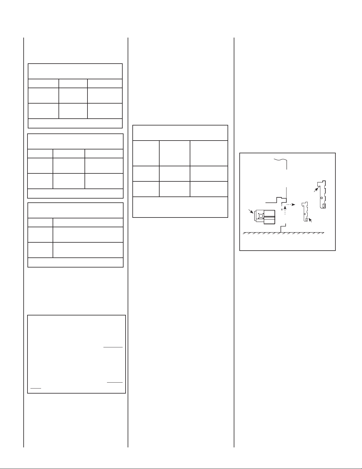
The gas controls can be found behind the control
compartment access door.
Removing Control Compartment Door:
Open the door by gently liftint it upward until the
hook catches on boths sides clear the locating
slots. Then pull door out to remove.
On millivolt systems, the piezo igniter, HI/LO
fl ame adjustment knob, and pilot and main
gas OFF/ON control knob are located below
the glass panel enclosure. The gas valve for
electronic systems is also located below the
glass enclosure panel. See Figure 1.
Reinstalling Control Compartment Door:
To reinstall, insert the hook catches on each
side of the door into the corresponding slots
in the control compartment opening, then
gently push forward and side down until it
locks in place.
Lift the Lower Control
OPENING CONTROL
COMPARTMENT DOOR
Control Valve
Compartment Door
up and pull out to
remove.
Hook Catch
Out
Up
Lower Control
Compartment Door
Figure 1
Operation of millivolt and electronic gas control systems are different. Before lighting and
operating your appliance determine if you have
a millivolt or electronic appliance. Familiarize
yourself with the gas control valve that your
appliance uses. Refer to Figure 1 for access
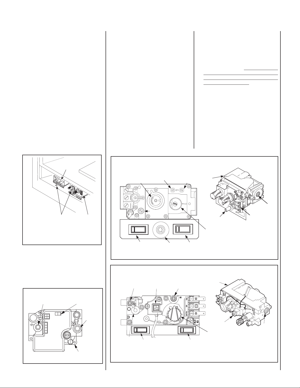
to the gas control valve.
Millivolt Appliances - Appliances with
Millivolt systems will be fi tted with the gas
control valve shown in Figures 4 or 5.
Electronic Appliances - Appliances with
electronic systems will be fi tted with the
electronic valve shown in Figure 3.
Millivolt Appliances - To light millivolt appliances refer to the detailed lighting instructions
found on Pages 17 & 18 . Millivolt appliance
lighting instructions may also be found on the
pull out lighting instruction labels attached to
the gas control valve.
Millivolt appliances are fi tted with an OFF/ON
Rocker Switch located behind the control
compartment access door, below the appliance front glass enclosure panel (see Figure 1
for location). Once the pilot is lit, the OFF/ON
rocker switch will control the appliance OFF/ON
burner operation. To operate: Toggle the switch
between its ON and OFF positions.
4
NOTE: DIAGRAMS & ILLUSTRATIONS NOT TO SCALE.
Page 5
If your millivolt appliance is equipped with an
optional remote switch kit (wall switch, remote
control or wall thermostat) and the pilot is lit,
the appliance main burner may be turned on
and off using the optional switch. When using
an optional remote switch, turn off the standard
OFF/ON switch.
OPERATION AND CARE OF YOUR
APPLIANCE
The standard controls for appliance operation
are located behind the panel below the appliance front glass enclosure panel (see Figure
1). Optional control switches are also available
(see Page 14 - Remote Wall Switch, Remote
Control or Wall Thermostat).
Note: To prevent excessive resistance in burner
circuit (which can cause burner operation problems), only one burner control switch should be
wired to valve. Therefore, if an optional control
switch is installed, the standard Off/On switch
and wires should be removed.
If your electronic appliance is equipped with an
optional remote wall switch or remote control kit
the appliance main burner may be turned on and
off with the wall switch or remote control.
If your electronic appliance is not equipped
with a wall switch or remote control, the main
burner must be turned off and on with the gas
control switch. Toggle the switch from ON to
OFF to operate the main burner.
Variable Flame Height Adjustment
(Millivolt Appliances only)
1. All Millivolt appliances are equipped with a
variable gas control valve. Flame height for
these models may be adjusted through a
range between fi xed low and high settings
while the appliance is in operation.
Adjust the fl ame height as desired after lighting
the appliance by rotating the variable adjustment
control knob (HI/LO) located on the front of the
valve (refer to Figures 4 & 5).
2. During the fi rst initial burns of these appli-
ances, there will be some odor emitted (see
Burn-In Period on Page 4).
3. Keep the lower control compartment clean
by vacuuming or brushing at least twice a
year. More frequent cleaning may be required
due to excessive lint from carpeting, bedding
materials, pet hair, etc. It is very important
that the control compartments, burners
and circulating air passageways of the
appliance are kept clean.
4. Always turn off gas to the pilot (millivolt
appliances) and let the appliance cool down
before cleaning. Before re-lighting, refer to
the lighting instructions in this manual. Lighting instructions may also be found on the
pull out lighting instruction labels attached
to the gas control valve.
5. Always keep the appliance area clear and
free from combustible materials, gasoline
and other fl ammable liquids.
6. Remember, Millivolt appliances have a continu-
ous burning pilot fl ame. Exercise caution when
using products with combustible vapors.
SIT Gas Valve
Shown with control
compartment door
removed
Piezo Igniter
Honeywell
Gas Valve
Sit and Honeywell Millivolt Gas Valve
Showing Piezo Igniter Location (Each Unit is
Equipped with Only One of these Gas Valves)
Figure 2
Electronic Appliances -
To light electronic appliances refer to the detailed
lighting instructions found on Pages 19 & 20
of these instructions. Electronic appliance
lighting instructions may also be found on the
pull out lighting instruction labels attached to
the gas control valve.
Honeywell Electronic Gas Valve
Manifold Pressure
Port
I
G
N
I
T
ER
Figure 3
C
O
N
T
R
NO
O
FFO
L
ON / OFF Switch
Inlet
Pressure
Port
NI
PSI
Electronic Gas
Control Valve
HI/LO Variable Flame
Height Adjustment
T
P
T
H
T
P
T
H
L
O
T
OFF
Optional Burner OFF/ON
Rocker Switch
Figure 4
Manifold Pressure
Tap
H
I
O
L
OFF
HI/LO Variable
Flame Height
Adjustment
Optional Burner OFF/ON
Rocker Switch
Figure 5
Manifold Pressure Tap
I
H
L
W
O
Pilot Adjustment
P
I
Screw
ON
Piezo Igniter
Piezo Igniter
N
ON
SIT Millivolt Gas Valve
Gas
Inlet Pressure Tap
IN
OUT
F
F
O
P
I
L
O
ti
T
O
N
ON
OFF
Inlet
Piezo Igniter
Main Gas
Control Knob
OFF/PILOT/ON
Optional Blower OFF/ON Rocker Switch
Honeywell Millivolt Gas Valve
Gas
Inlet Pressure Tap
F
F
T
O
O
L
I
P
O
Optional Blower OFF/ON
Rocker Switch
ON
OFF
Outlet
Piezo Igniter
Main Gas
Control Knob
OFF/PILOT/ON
Gas
Outlet
Terminals
TPTH,TP & TH
Gas
Inlet
NOTE: DIAGRAMS & ILLUSTRATIONS NOT TO SCALE.
5
Page 6
MAINTENANCE
(See Maintenance Schedule, Page 21)
Refer to the maintenance schedule for maintenance
tasks, procedures, periodicity and by whom they
should be performed. Always verify proper operation of the appliance after servicing.
Before re-lighting the fi replace, refer to the
lighting instructions in this manual. Instructions are also found on pull-out panels
located below the glass door in the control
compartment.
IMPORTANT
It is imperative that the control
compartment, burners and
circulating air passage ways of
appliance be kept clean.
Cleaning Glass
(see Front Glass Enclosure Panel, Removal and
Installation on Pages 7).
Clean Logs And Burner
Carefully remove the logs (use care when handling the fi ber logs, as they become quite fragile
after curing). Vacuum out any foreign matter
(lint, carbon, etc). on the burner. Ensure the
burner ports are “open.” Remove any carbon
deposits from the under side of the logs using
a vacuum cleaner, or a soft bristled brush (i.e.
paint brush). Note: Improper positioning of
logs can create carbon build-up and will alter
the performance of the appliance.
Replacing Logs -
WARNING
Turn off gas and electrical power
before servicing the appliance.
CAUTION
Wear gloves and safety Glasses
for protection while doing
required maintenance
.
IMPORTANT
Always verify proper operation
after servicing.
Inspect Venting System
The appliance and venting system should be
thoroughly inspected before initial use and at
least annually by a qualifi ed service technician
(inspection should include ensuring that exhaust
or intake passages are unobstructed and vent
components are properly assembled and not
damaged). If the venting system is disassembled
for any reason, a qualifi ed service technician
should follow vent installation instructions for
proper reassembly and proper sealing of the
venting system components. However, more
frequent periodic inspections and cleanings
should be performed by the homeowner.
Clean Lower Control Compartment
Keep lower control compartment clean by vacuuming or brushing it out at least twice a year (also
clean the air venturi with a brush or wire). More
frequent cleaning may be required due to accumulation of lint from carpeting, bedding materials, pet
hair, spider webs, etc. It is very important that
control compartments, burners, circulating air
passageways and air venturi on the appliance
are NOT obstructed in any way.
6
Note: Clean glass after fi rst two weeks of operation (after Burn-In period is over) and then only
when necessary and when the fi replace is cool.
Wipe surface with clean, dampened, soft cloth.
Follow with dry, soft towel as desired. Take care
not to scratch the glass surface.
The viewing glass should be cleaned periodically to
remove any build-up caused from the following:
IMPORTANT
Do not use abrasive cleaners
on glass. Never clean the glass
when it is hot.
• During start-up, it is normal for condensation to form on the inside of the glass (this
condensation and fog will usually disappear
in a few minutes). The moisture can cause
lint, dust and other airborne particles to cling
to the glass surface.
• Initial curing of the high temperature paint
and burning off of lubricants used in the
manufacturing process may result in a fi lm
on the glass.
• A white coating may form on the glass as a
result of impurities and minerals in the fuel.
It is recommended that the glass be cleaned
two or three times during each heating season,
depending on the circumstances present. The
following cleaning solutions are approved for use
to clean glass:
• Non-ammonia based household cleaner
• 50%-50% mix of white vinegar & water
• Gas fi replace/stove glass cleaner
Inspect Glass Gasket - Visually inspect the
gasket on the backside of the glass enclosure
panels. The gasket surface must be clean, free
of irregularities and seated fi rmly.
NOTE: DIAGRAMS & ILLUSTRATIONS NOT TO SCALE.
If the logs become damaged by accident or improper handling and need replacement, use only
the proper replacement logs from manufacturer
(see Page 24 for ordering information).
Re-Install Embers, Logs and Volcanic Stone
- Carefully follow placement instructions on
Pages 8 to 10). All logs should fi t onto corresponding pins and/or log stoppers. This will
ensure a proper fl ame and safe combustion.
Inspect Wiring
Refer to wiring diagrams on Page 13.
WARNING
Label all wires prior to disconnection when servicing controls. Wiring errors can cause
improper and dangerous operation. Verify proper operation
after servicing.
Inspect and clean all wire connections. Ensure
that there is no melting or damage. Inspection
should include:
• Terminals at the Valve
• OFF/ON Switch
• (Optional Control Switch) Wall Thermostat,
Remote Control or Remote Wall Switch Kit
Inspect Burner Flame Appearance
Ensure that the burner flame appearance
resembles the fl ame shown in Figure 10 and
as described in Flame Appearance and Sooting
on Page 11. The Homeowner must contact
a qualifi ed service technician at once if any
abnormal condition is observed.
Small Area Paint Touch-up
The fi nish of the appliance is a high quality powdercoat. Only use factory supplied powdercoat
paint kit for touch-ups. Paint is available at your
local authorized LHP dealer, cat. no. 90L74.
Never attempt to paint a hot fi replace.
Page 7
Do not attempt to repaint the appliance until the
fi nish is completely cured (see Burn-In Period
on Page 4). If the surface later becomes stained
or marred, it may be lightly sanded and touched
up with spray paint.
Front Glass Enclosure Panel, Removal
and Installation
WARNING
Do not operate appliance with
the glass front removed, cracked
or broken. Replacement of
the glass should be done by a
licensed or qualifi ed service
technician.
WARNING
Do not attempt to substitute the
materials used on this door, or
replace cracked or broken glass
with any materials other than
those provided by the appliance
manufacturer.
WARNING
Handle this glass with extreme
care! Tempered glass is susceptible to damage – do not scratch
or handle roughly while reinstalling the glass door frame.
WARNING
The glass door of this appliance must only be replaced as
a complete unit as provided by
the manufacturer. Do not attempt
to replace broken, cracked or
chipped glass separately.
These are direct-vent appliances. They are
designed to operate only when the front glass
enclosure panel is installed. Generally the front
glass enclosure panel should not be removed
except to gain access to the components within
the fi rebox, and the appliance may only be operated without the front glass enclosure panel
in place for very brief periods of time during
appliance checkout and adjustment. Note: The
fl ame appearance will be diminished while the
front glass enclosure panel is removed.
During this appliance checkout and adjustment period, a potential safety hazard exists
- EXERCISE EXTREME CAUTION to prevent
the occurrence of any burn injuries from the
exposed fl ames or hot sur faces. Also note, that
while the front glass enclosure panel (or any of
the panels) is removed, the fl ame appearance
will appear to be smaller than normal.
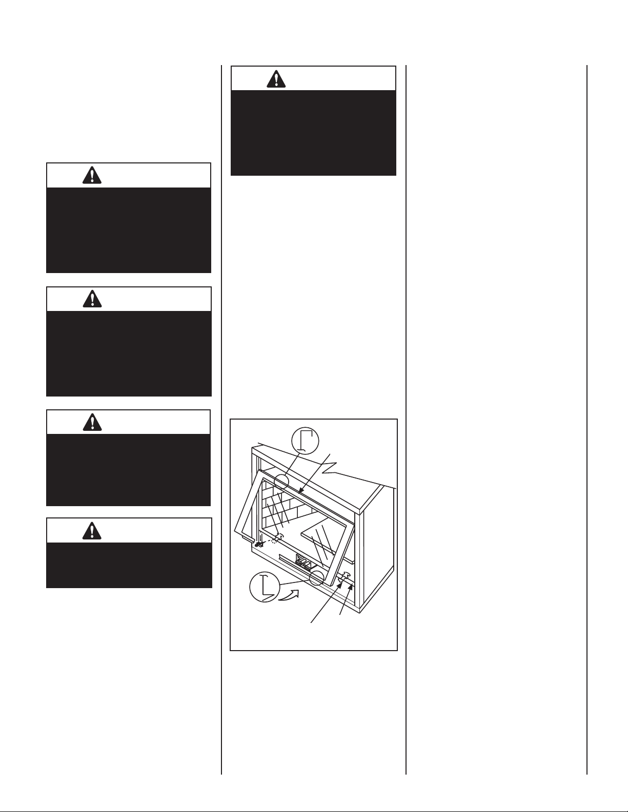
Top Flange on
Glass Door
Glass Door
Removing Glass Enclosure Panels
(see Figure 6)
1. Remove the top louver assembly by lifting
it up and pulling it out.
2. Remove the control compartment access
door (see removal instructions on Page 4
- Removing Control Compartment Door).
3. Locate the two (2) latches at the top of the
control compartment. To disengage the two
latches from the bottom vee-fl ange of the
glass enclosure panel, reach for the handles
located towards the back of the latches and
pull the handles down toward the front of
the appliance.
4. Swing the bottom of the door out and raise
it slightly to lift the top fl ange of the door
frame away from the appliance.
Installing Glass Enclosure Panels
(see Figure 6)
1. Visually inspect the gasket on the backside
of the glass panel. The gasket surface must
be clean, free of irregularities and seated
fi rmly.
2. Position the glass enclosure panel in front
of the fi rebox opening at a 45 degree angle
and engage the top fl ange over the lip at the
top of the fi rebox opening. See Figure 6.
3. Swing the glass enclosure panel down and
back. Ensure the gasket seats evenly as the
panel draws shut. Engage the Vee-fl ange at
the bottom of the panel with the latches and
close the latches to secure the panel.
WARNING
Do not attempt to touch the front
enclosure glass with your hands
while the fi replace is in use.
Bottom Vee-fl ange
Glass Door
Glass Door Latch
Firebox Floor
Figure 6 - INSTALLING GLASS DOOR
NOTE: DIAGRAMS & ILLUSTRATIONS NOT TO SCALE.
4. Reinstall top louver assembly and control
compartment door see installation instructions on Page 4, Reinstalling Control
Compartment Door).
7
Page 8
INSTALL VOLCANIC STONE, GLOWING
EMBERS AND LOGS
1. Remove front glass enclosure panel (see Re-
moving Glass Enclosure Panels on this page).
2. Carefully remove log set box from fi rebox.
Next, remove embers and volcanic stone
from the control compartment. Handle logs
carefully to prevent breakage.
3. Install Decorative Volcanic Stone - Mound
up a portion of the volcanic stone in front of
the burner in a pleasing pattern.
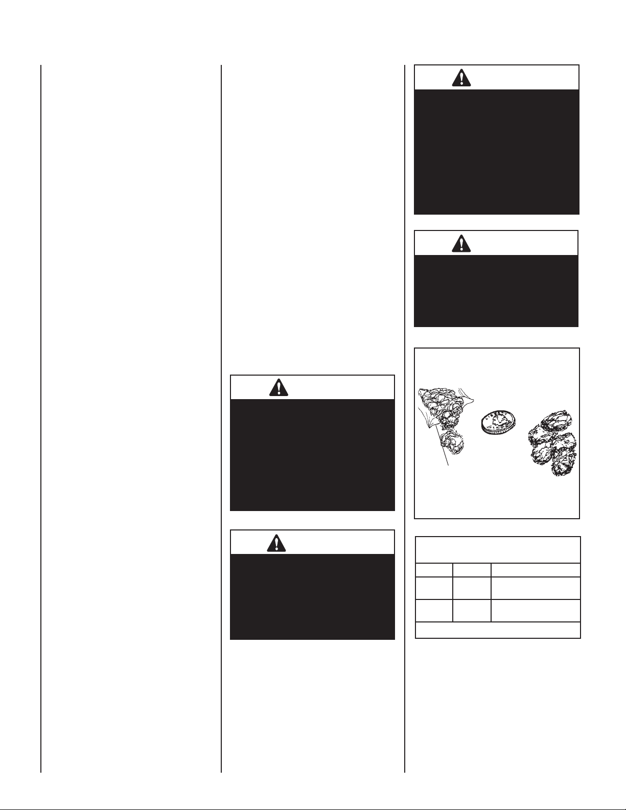
4. Placement of Glowing Embers -
Separate the Embers (rockwool) into pieces
about the size of a quarter (see Figure 7).
Keep the pieces fl uffed up, not matted.
Distribute these pieces over the surface of
the burner, as shown in Figures8 or 9. Do
not use more than is necessary. Ensure that
the main burner ports remain uncovered by
the ember material.
Note: This appliance is provided with enough
Glowing Embers for several applications, do
not use all that is in a new bag at one time.
For best glowing effect, replace the ember
material annually.
5. Placement of Logs -
The logs have locating notches or slots to
help ensure that they are properly positioned.
Proper log placement is critical to prevent
sooting.
SSDV-3530 - Install as Follows
Carefully position the ceramic fi ber logs into the
fi rebox as shown in Figure 8. Logs should be
placed in the order shown and per the following
instructions.
1. Place embers on the front burner tube and
volcanic stone in front of the burner as
shown and per instructions on this Page
(see Placement of Glowing Embers & Install
Decorative Volcanic Stone on this Page).
2. Place the rear log (A) as shown. Position the
2 notches on the bottom of log (A) over the 2
corresponding locating brackets as shown.
3. Place the center log (C) as shown. The 2
notches on the bottom of log (C) fi t over
the corresponding locating brackets.
4. Place the left log (B) as shown. The top fork
on log (B) fi ts into the notch on log (A). The
bottom of log (B) rests on the subfl oor.
5. Place the top right log (D) as shown. The top
fork on log (D) fi ts into notch on log (A) as
shown. The bottom fork on log (D) rests on
subfl oor fl ange (identifi ed in photo #1).
SSDV-4035 - Install as Follows
Carefully position the ceramic fi ber logs into the
fi rebox as shown in Figure 9. Logs should be
placed in the order shown and per the following
instructions.
1. Place embers on the front burner tube and
volcanic stone in front of the burner as
shown and per instructions on this Page
(see Placement of Glowing Embers & Install
Decorative Volcanic Stone on this page).
2. Place the rear log (A) as shown. Position
the 2 notches on the bottom of the log over
the 2 corresponding locating brackets as
shown.
3. Place the center log (C) as shown. The 2
notches on the bottom of the log should fi t
over the corresponding locating brackets.
4. Place the top right log (D) as shown. The top
fork on log (D) fi ts into notch on log (A) as
shown. The bottom fork on log (D) rests on
subfl oor fl ange (identifi ed in photo #1).
5. Place the top left log (B) as shown. The top
fork on log (B) fi ts into notch on log (A). The
bottom of the log rests on the subfl oor.
WARNING
If logs are not installed according
to the log installation instructions, fl ame impingement and
improper combustion could
occur and result in soot and/or
excessive production of carbon
monoxide (CO), a colorless,
odorless, toxic gas.
WARNING
DO NOT attempt to install the logs
until the appliance installation
has been completed, the gas line
connected and tested for leaks
and the initial burner operation
has been checked out.
WARNING
The size and position of the log set
was engineered to give the appliance a safe, reliable and attractive fl ame pattern. Any attempt
to use a different log set in the
fi replace will void the warranty
and will result in incomplete
combustion, sooting, and poor
fl ame quality.
WARNING
This appliance is not designed
to burn wood. Any attempt to
do so could cause irreparable
damage to appliance and prove
hazardous to your safety.
Separate into Quarter
Size (separate) Pieces
Bag of Glowing
Embers (rockwool)
Figure 7 - Glowing Embers
REFERENCE
Firebox Accessories / Parts
Cat. No. Model No. Description
88L53 FGE Bag of Glowing Embers
80L42 FDVS
Table 8
(1 oz. rockwool)
Bag of Decorative
Volcanic Stone
8
NOTE: DIAGRAMS & ILLUSTRATIONS NOT TO SCALE.
Page 9
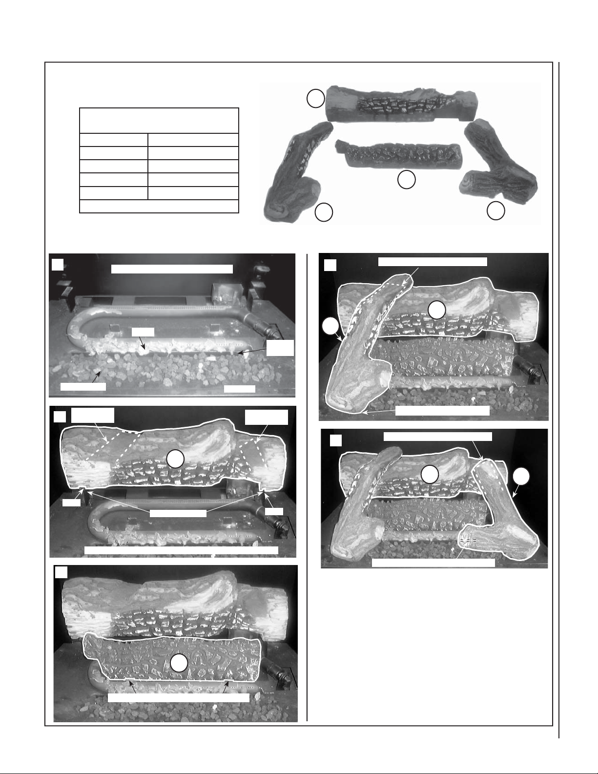
MODEL SSDV-3530
Log Placement Instructions
LOG SET
Catalog Number
* Item
A
B
C
D
* Item "letters" above correspond to photos
Install the Embers, Volcanic Stone and Logs in the order shown here
(1 through 5) and per the instructions on Page 8.
H3367
Description
Log, Rear
Log, Top Left
Log, Center
Log, Top Right
A
C
B
D
1
Volcanic Stone
Notch for top
2
left log (B)
Notch
Place Embers & Volcanic Stone as Shown
Embers
A
Locating Brackets
Sub-Floor
Sub-Floor
Flange
Notch for top
right log (D)
Notch
4
Top fork on log (B) fi ts into notch on log (A)
A
B
Bottom of log (B) rests on Sub-Floor
5
Top fork on log (D) fi ts into notch on log (A)
A
D
The 2 notches on the bottom of log (A) rest on the locating brackets
Bottom Fork of log (D) rests on Sub-Floor Flange
3
C
Notches on bottom of log (C) fi ts over 2 locating brackets
Figure 8
NOTE: DIAGRAMS & ILLUSTRATIONS NOT TO SCALE.
9
Page 10
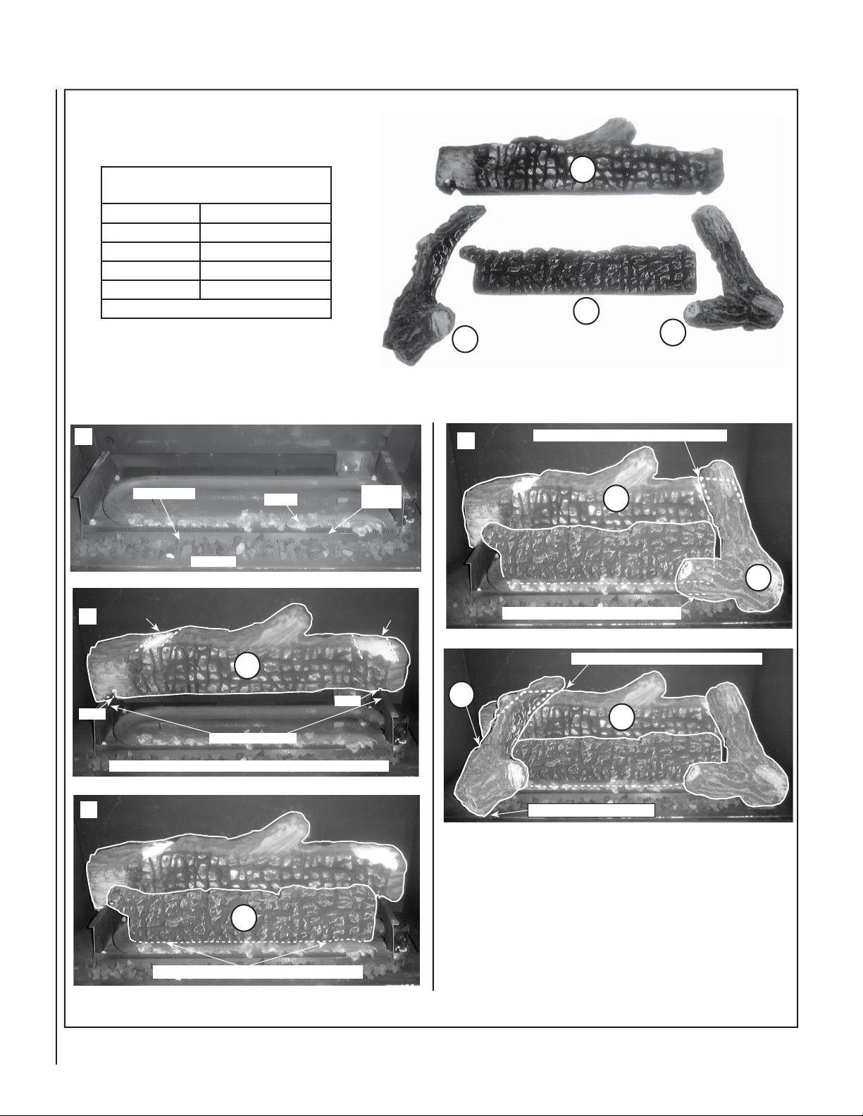
MODEL SSDV-4035
Log Placement Instructions
LOG SET
Catalog Number
* Item
A
B
C
D
* Item "letters" above correspond to photos
Install the Embers, Volcanic Stone and Logs in the order shown here
(1 through 5) and per the instructions on Page 8.
1
Notch for Top Left log (B)
2
Place Embers and Volcanic Stone as Shown
Volcanic Stone
Sub-Floor
H3368
Description
Log, Rear
Log, Top Left
Log, Center
Log, Top Right
Embers
Sub-Floor
Flange
Notch for Top
Right log (D)
A
B
4
Top fork on log (D) fi ts into notch on log (A) as shown
Bottom Fork of log (D) rests on Sub-Floor Flange
C
D
A
D
10
A
Notch
Locating Brackets
The 2 notches on the bottom of log (A) rest on the locating brackets
3
C
Slots on bottom of Log (C) fi ts over 2 locating brackets
Figure 9
Notch
NOTE: DIAGRAMS & ILLUSTRATIONS NOT TO SCALE.
B
Top fork on log (B) fi ts into notch on log (A) as shown
A
Bottom of log (B) rests on subfl oor
Page 11
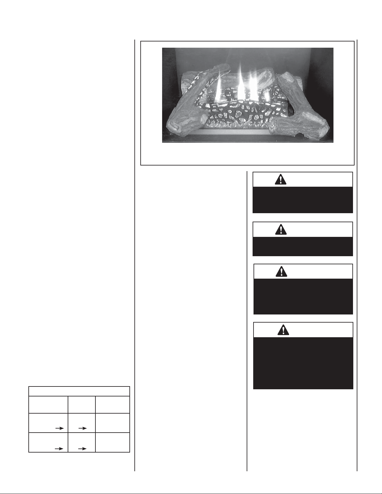
BURNER ADJUSTMENTS
(QUALIFIED TECHNICIANS ONLY)
Flame Appearance and Sooting
Proper fl ame appearance is a fl ame which is
blue at the base and becomes yellowish-orange
in the body of the fl ame. When the appliance
is fi rst lit, the entire fl ame may be blue and
will gradually turn yellowish-orange during
the fi rst 15 minutes of operation. If after a
short period the fl ame stays lowered blue, or
if the fl ame is orange with evidence of sooting
(black tip), the air shutter opening may need
to be adjusted.
If the air shutter openings closed too far,
sooting may develop. Sooting is indicated
by black puffs developing at the tips of very
long orange fl ames. Sooting results in black
deposits forming on the logs, appliance inside
surfaces and on exterior surfaces adjacent
to the vent termination. Sooting is caused
by incomplete combustion in the fl ames and
lack of combustion air entering the air shutter
opening. To achieve a warm yellowish-orange
fl ame with an orange body that does not soot,
the shutter opening must be adjusted between
these two extremes.
Figure 10 - Burner Flame Appearance Models SSDV-3530 & SSDV-4035 Series
Burner Air Shutter Adjustment Procedure
1. Locate adjustment rod and adjust air shutter
to the standard setting as shown in Figure
11 (adjustment rod is located in the lower
control compartment). Note: Rotating the
adjustment rod counterclockwise increases
air and clockwise decreases air.
Air shutter adjustment should
only be performed by a qualifi ed
professional service technician.
WARNING
Air Shutter Adjustment Guidelines
• If there is smoke or soot present, fi rst check
the log set positioning to ensure that the
fl ames are not impinging on any of the logs.
If the log set is properly positioned and a
sooting condition still exists, then the air
shutter opening should be increased.
• The more offsets in the vent system, the larger
the air shutter opening will need to be.
• An appliance operated with the air shutter
opened too far, may have fl ames that appear
blue and transparent. These weak, blue and
transparent fl ames are termed anemic.
• Propane models may exhibit fl ames which
candle or appear stringy. If this is present
and persists, adjust the air shutter to a more
closed position, then operate the appliance
for a few more minutes to ensure that the
fl ame normalizes and the fl ames do not
appear sooty.
The following chart is provided to aid you in
achieving the correct air shutter adjustment
for your installation.
Air Shutter Adjustment Guidelines
Amount of
Primary Air
If air shutter is
closed too far
If air shutter is
open too far
Flame
Color
Flame will
be orange
Flame will
be blue
Air shutter
gap should be
increased
Air shutter
gap should be
decreased
:
Air Shutter
Adjustment
2. Light appliance (follow lighting procedure on
lighting label in control compartment or see
homeowners manual).
3. Allow the burner to operate for at least 15 min-
utes while observing the fl ame continuously
to ensure that the proper fl ame appearance
has been achieved (see Figure 10). If the
following conditions are present, adjust
accordingly.
• If flame appears weak or sooty, adjust
the air shutter, incrementally, to a more
open position until the proper fl ame
appearance is achieved.
• If fl ame stays lowered blue, adjust the
air shutter, incrementally, to a more
closed position until the proper fl ame
appearance is achieved.
4. Leave the control knob (off/pilot/on) in the
ON position and the burner OFF/ON switch
OFF (& remote switches, if applicable).
5. When satisfi ed that the burner fl ame ap-
pearance is normal, close the lower control
compartment door.
WARNING
Ensure front glass panel is in place
and sealed during adjustment.
CAUTION
The air shutter door and nearby
appliance surfaces are hot. Exercise caution to avoid injury while
adjusting fl ame appearance.
CAUTION
Carbon will be produced if the air
shutter is closed too much. Any
damage due to carboning resulting from improperly setting the
air shutter is not covered under
the warranty.
NOTE: DIAGRAMS & ILLUSTRATIONS NOT TO SCALE.
11
Page 12
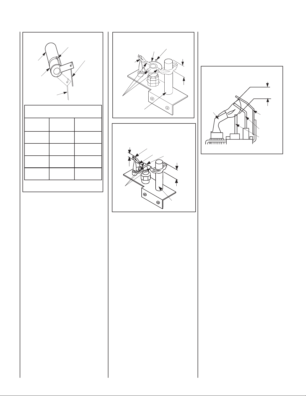
Burner Air Shutter Adjustment
Adjustment Setscrew
Adjustment Rod Up
(Fully Open Position)
Burner Tube
Air Shutter
SIT MILLIVOLT PILOT ASSEMBLY
Proper Pilot Flame Appearance
Hood
Thermocouple
Igniter Rod
3/8" Min.
(9 mm)
Electronic Appliance Checkout
To light the burner, refer to the lighting instructions on Pages 19 & 20. Ensure the igniter
lights the pilot. The pilot fl ame should engulf
the fl ame sensor as shown in Figure 14.
ELECTRONIC PILOT ASSEMBLY
Proper Pilot Flame Appearance
Adjustment Rod Down
(minimum air opening
position)
Ref. Air shutter Patent:
U.S. Pat. 5,553,603
Main Burner Factory Air Shutter
Opening Setting - Inches (millimeter)
Model Natural
SSDVT-3530
SSDVR-3530
SSDVT-4035
SSDVR-4035
(6.35 mm)
(6.35 mm)
(6.35 mm)
(6.35 mm)
Gas
1/4
1/4
1/4
1/4
Propane
Gas
1/2
(12.70 mm)
1/2
(12.70 mm)
1/2
(12.70 mm)
1/2
(12.70 mm)
Figure 11
Millivolt Appliance Checkout
The pilot fl ame should be steady, not lifting
or fl oating. Flame should be blue in color with
traces of orange at the outer edge.
The top 3/8" (10 mm) at the pilot generator
(thermopile) and the top 1/8" minimum (tip)
of the quick drop out thermocouple should be
engulfed in the pilot fl ame. The fl ame should
project 1" (25 mm) beyond the hood at all three
ports. See Figure 12 or 13.
To light the burner, refer to the lighting instructions on Pages 17 & 18.
Pilot
Nozzels
Figure 12
HONEYWELL MILLIVOLT PILOT ASSEMBLY
Thermopile
Proper Pilot Flame Appearance
Thermocouple
1/8" Min.
(3 mm)
Igniter Rod
Hood
Pilot
Nozzels
Figure 13
Thermopile
3/8" Min.
(9 mm)
Proper Flame
Adjustment
Pilot
Nozzels
3/8" to 1/2"
(9 -13 mm)
Ground
Electrode
Flame Rod
Hot Surface
Igniter
Figure 14
With proper care and maintenance, your appliance will provide many years of enjoyment. If
you should experience any problem, fi rst refer
to the troubleshooting guide in this manual.
If problem persists, contact your Lennox
distributor.
12
NOTE: DIAGRAMS & ILLUSTRATIONS NOT TO SCALE.
Page 13
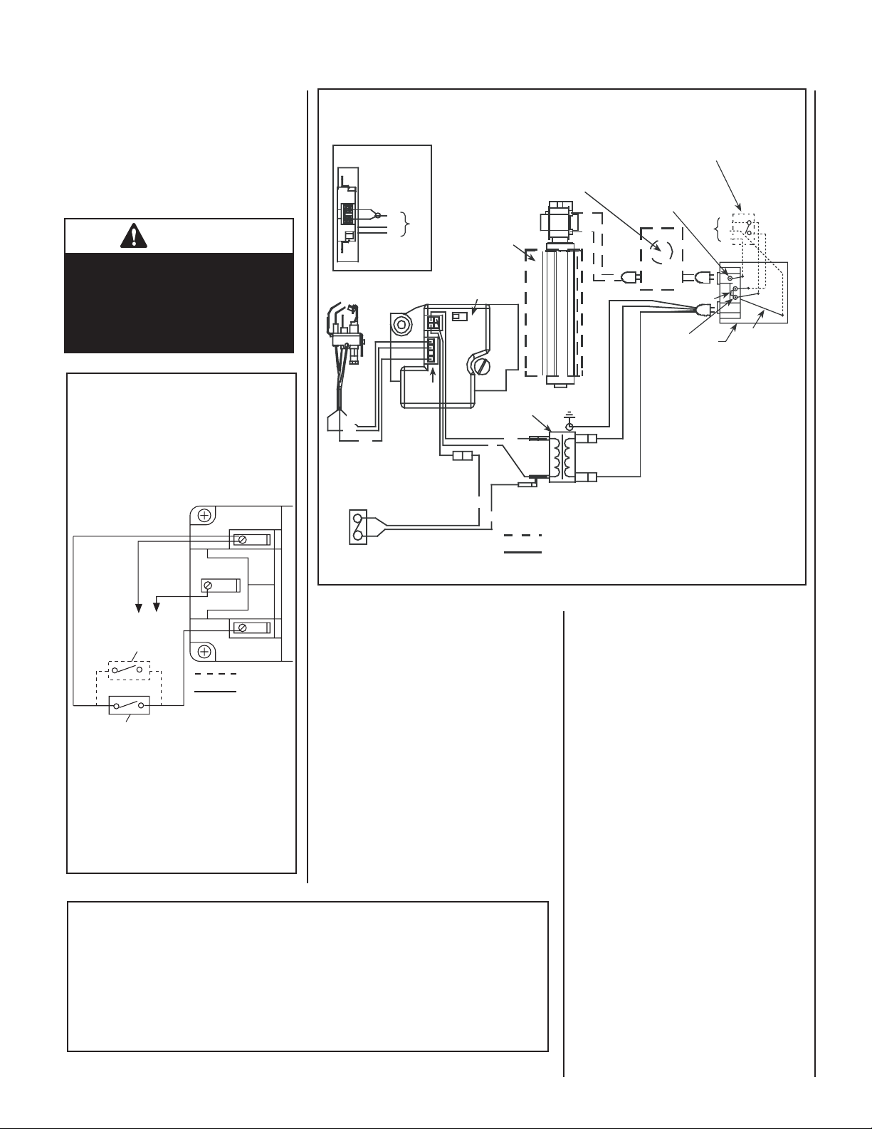
WIRING DIAGRAMS
Wiring diagrams are provided here for reference purposes only. This information is also
provided on schematics attached directly to the
appliance on a pullout panel located within the
control compartment.
CAUTION
Label all wires prior to disconnection when servicing controls. Wiring errors can cause
improper and dangerous appliance operation.
Millivolt Wiring Diagram
Schematic Representation Only
If any of the original wire as supplied must
be replaced, it must be replaced with Type
AWM105 C - 18 gage wire.
TH
TP
TP
Electronic Wiring Diagram (Honeywell) Showing Blower Wiring for Optional FBK-100, FBK-200 & FBK-250 Kits
Schematic Representation Only
Wall Mounted Blower Speed Control Switch or
Auxiliary View A
J-Box Wiring when
using unit mounted
relay module.
BK
W
G
Junction Box
Pilot Burner
Assembly
BL
BL
BK
Optional Control Switch
C
AV
02
1
Igniter
Connector
Relay Module C/W FBK-250 only. Plug blower
into J-Box receptacle for FBK-100 or FBK-200
application. View A for J-Box wiring.
Optional Blower
*OFF/ON Switch
(Integral with
Gas Valve)
Honeywell
Electronic
Gas
Valve
24 V
Secondary
GROUND
Field Wired
Factory
Wired
Transformer
BL
R
BK
BK = BLACK BL = BLUE
BK
R = RED W = WHITE
W
G = GREEN
ON/OFF Switch for Blower Kit (optional)
Outlet Box Green
Ground Screw
Break off Tab
Hot side
of Outlet
* Leave the OFF/ON switch, which is
integral with the gas valve, in the ON
position.
** Optional Control Switches: Wall
Switch, Wall Thermostat or Remote
120 VAC
Primary
Control Receiver.
Notes:
1. If any of the original wire as supplied
must be replaced, use Type AWM 105°C
- 18 gage wire ONLY.
2. 120 VAC, 60 Hz - Less than 3 Amps.
Caution: label all wires prior to
disconnection when servicing controls.
Wiring errors can cause improper and
dangerous operation.
120
VAC
Junction
Box
BK
W
G
G
BK
R
White Wire
to Opposite
Side (neutral)
Figure 16
TH
Thermopile
*Optional Switch
Field Wired
Factory
Wired
Standard OFF/ON Switch
* Optional Kits Installed - OFF/ON wall switch,
wall thermostat or remote control receiver.
Note: Turn the appliance-mounted OFF/ON
burner control switch to the OFF position if
any of these kits are installed.
WARRANTY
Your gas appliance is covered by a limited twenty
year warranty. You will fi nd a copy of the warranty accompanying this manual. Please read
the warranty to be familiar with its coverage.
Retain this manual. File it with your other documents for future reference.
PRODUCT REFERENCE INFORMATION
We recommend that you record the following
important information about your fi replace.
Please contact your Lennox dealer for any
questions or concerns. For the number of
your nearest Lennox dealer, please call 1-800-
Figure 15
9-LENNOX.
Visit us at www.Lennox.com
Your Fireplace's Model Number ________________________________________
Your Fireplace's Serial Number ________________________________________
The Date On Which Your Fireplace Was Installed ___________________________
The Type of Gas Your Fireplace Uses ____________________________________
REPLACEMENT PARTS
A complete parts list is found at the end of
this manual. Use only parts supplied from the
manufacturer.
Normally, all parts should be ordered through
your Lennox distributor or dealer. Parts will be
shipped at prevailing prices at time of order.
When ordering repair parts, always give the
following information:
1. The model number of the appliance.
2. The serial number of the appliance.
3. The part number.
4. The description of the part.
5. The quantity required.
6. The installation date of the appliance.
If you encounter any problems or have any questions concerning the installation or application
of this system, please contact your distributor,
or Lennox directly:
LHP
1110 West Taft Avenue
Orange, CA 92865
Your Dealer's Name ________________________________________________
NOTE: DIAGRAMS & ILLUSTRATIONS NOT TO SCALE.
13
Page 14

ACCESSORY COMPONENTS
Product Reference Information
Cat.
No.
H3325 SSDVT-3530CNM 115 lbs 37W x 17D x 36H
H3326 SSDVT-3530CNE 115 lbs 37W x 17D x 36H
H3327 SSDVR-3530CNM 115 lbs 37W x 17D x 36H
H3328 SSDVR-3530CNE 115 lbs 37W x 17D x 36H
H3329 SSDVT-4035CNM 125 lbs 42W x 17D x 41H
H3330 SSDVT-4035CNE 125 lbs 42W x 17D x 41H
H3331 SSDVR-4035CNM 125 lbs 42W x 17D x 41H
H3332 SSDVR-4035CNE 125 lbs 42W x 17D x 41H
Cat. No. Model No. Description
85L87 FWSK OFF/ON Wall Switch Kit
Model Ship.
Wt.(lbs)
White Wall Switch Kit
Ship.Vol.
(inches)
(13.1 cu.ft).
(13.1 cu.ft).
(13.1 cu.ft).
(13.1 cu.ft).
(16.9 cu.ft).
(16.9 cu.ft).
(16.9 cu.ft).
(16.9 cu.ft).
Remote Control Kit, Standard
Cat. No. Model No. Description
H0249 RCL Remote Control System
(Standard)
(ref. Form # 750,127M)
Standard Remote Control System
The Model RCL (Standard) Remote Control System,
features a simplistic OFF/ON control function for the
fi replace. This model includes a hand-held transmitter,
a remote receiver with wall-mount cover plate and
all hardware required to install the unit. The remote
receiver can be wall or hearth mounted.
The transmitter has ON and OFF functions that are
activated by pressing either button on the face of
the transmitter. When a button on the transmitter
is pressed, a signal light illuminates briefl y to verify
that a signal has been sent.
The Model RCL is designed to operate with all millivolt ignition systems, as well as electronic ignition
systems. It may be installed with use for either
natural gas or propane gas appliances. The RCL
offers ease of installation and allows you to execute
on-off commands to the fi replace effortlessly with
one simple motion.
The Model RCL comes complete with detailed operating instructions.
Remote Control Kit, Deluxe
Cat. No. Model No. Description
H0251 RCL-STAT Remote Control System
(Deluxe)
(ref. Form # 750,129M)
Deluxe Remote Control System
The Model RCL-T (Deluxe) Remote Control System
has all of the features of the standard system along
with an added easy to read LCD screen which presents
access to many enhancements, including; battery
power level indicator, timer, mode of operation,
thermostatic display including room temperature in
either metric of English units, fl ame indicator and
clock. Fully programmable, the Model RCL-T allows
for virtual command over nearly all operational and
temperature variables, using the hand held remote
control transmitter.
The Model RCL-T (Deluxe) remote control system
is installed in the same manner as the standard
system, may be operated with electronic and millivolt systems with either natural gas or propane gas.
The RCL-T comes complete with detailed operating
instructions.
OFF/ON Wall Switch Kit
The OFF/ON wall switch kit may be used to control
the operation of the fi replace burner. Install the
OFF/ON wall switch in a convenient location near
the fi replace.
Rocker Switch Kit
Cat. No. Model No. Description
80L41 FRS Rocker Switch Kit
(ref. Form # 750,037M)
Unit-Mountable Rocker Switch
This rocker switch kit can be installed directly in
the gas valve mounting bracket (millivolt gas valve
equipped fi replaces) to provide On/Off operation in
lieu of a wall switch.
14
Variable Speed Wall Switch
Cat. No. Model No. Description
045571H VSWS Variable Speed Wall Switch
Variable Speed Wall Switch
Provides variable speed control if optional blower
kit is purchased.
NOTE: DIAGRAMS & ILLUSTRATIONS NOT TO SCALE.
Wall Thermostat, Millivolt
Cat. No. Model No. Description
89L36 WTK Wall Thermostat Kit,
White
Wall Thermostat
The wall thermostat kit provides temperature control
for optimum comfort.
Page 15
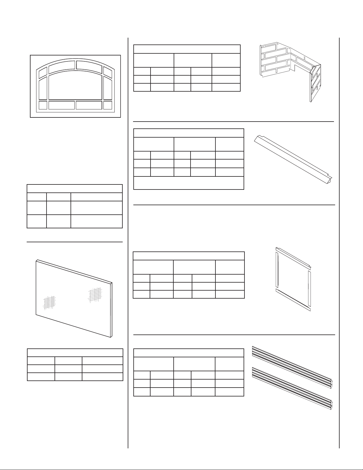
ACCESSORY COMPONENTS
Interior Brick Liner Kits
Rear Vent Top Vent Models
Where Used
Cat. # Model Cat. # Model
80L03 BLK-5R 80L01 BLK-5T SSDV-3530
80L04 BLK-6R 80L02 BLK-6T SSDV-4035
(ref. Form #750,023M)
Interior Brick Liner Kits
The brickade liner kits include tan stamped sheetmetal panels for the rear and side walls of the fi rebox. The
panels have brick-like features in relief. These kits can be retrofi tted into previously installed appliances.
Decorative Arch Screen Panel Kit
This easy to install optional screen installs over
the standard glass enclosure panel to provide
protection from inadvertant direct contact with the
hot glass surface. These screen panels cannot be
used in conjunction with the arch door kits or door
frame kits.
Decorative Arch Screen Panel Kit
Cat. No. Model Description
H3593 DASPK35TI 35” Decorative Arch Screen
Panel,SSDV-3530
H3594 DASPK40TI 40” Decorative Arch Screen
Panel,SSDV-4035
(ref. Form # 750,199M)
Eyebrow Hood Kits
Polished Brass Brushed Stainless
Cat. # Model Cat. # Model
96K67 EB35PB 88L49 EB35BS
96K68 EB40PB 88L50 EB40BS
* These hood kits replace the standard hood that comes with
these fi replaces.
(ref. Form #504,142M)
Models
Where Used
SSDV-3530
SSDV-4035
Polished Brass & Brushed Stainless Hood Kits
Attractive hoods are available in two styles. These hoods are designed to be fi tted to the glass viewing sides
of the appliance. In addition to providing an aesthetically pleasing appearance to your appliance installation,
the hood reduces heat effects to decorative mantles and fi nish materials located above the fi replace opening.
The hood kit replaces the standard hood that comes with these appliances and snaps into place. These kits
can be retrofi tted to previously installed appliances.
4 Piece Door Trim Kits
Polished Brass Brushed Stainless
Cat. # Model Cat. # Model
26M82 4DFK35PB 26M85 4DFK35BS SSDV-3530
26M83 4DFK40PB 26M86 4DFK40BS SSDV-4035
(ref. Form # 750,098M)
Models
Where Used
Screen Panel Kits
Cat. No. Model No. Models Where Used
26M48 HG35M SSDV-3530
26M49 HG40M SSDV-4035
(ref. Form # 750,101M)
Screen Panel Kit
This easy to install optional screen installs over the
standard glass enclosure panel to provide protection from inadvertant direct contact with the hot
glass surface. These screen panels cannot be
used in conjunction with the arch door kits or door
frame kits.
Door Frame Kits
A decorative door frame kit is available for use with these appliances. It is designed to attach directly to the front face
of the appliance at the four edges of the glass enclosure panel resulting in the appearance of a picture frame.
* Assembled 8-Piece Louver Kits
Polished Brass Brushed Stainless Models
Where Used
Cat. # Model Cat. # Model
H1524 LK-500B H1525 LK-500BS
H1526 LK-600B H1527 LK-600BS
(ref. Form # 750,166M)
* Superior Nameplate Logo, 56L93, is not included.
SSDV-3530
SSDV-4035
Polished Brass & Brushed Stainless Louvers Kits
These kits include a top 4-louver assembly and a bottom 4-louver assembly. They provide a touch of elegance.
These kits can be retrofi tted to previously installed appliances.
NOTE: DIAGRAMS & ILLUSTRATIONS NOT TO SCALE.
15
Page 16
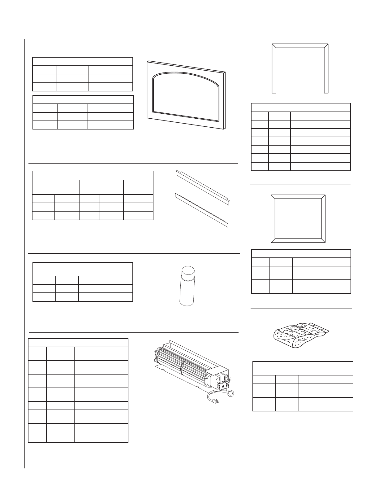
ACCESSORY COMPONENTS
Arch Door Kit - Polished Brass
Cat. No. Model Fireplace Model
26M43 ADK35CMPB SSDV-3530
81L35 ADK40CPB SSDV-4035
Arch Door Kit - Brushed Stainless Steel
Cat. No. Model Fireplace Model
26M44 ADK35CMBS SSDV-3530
98L69 ADK40CBS SSDV-4035
(ref. Form # 750,021M)
Arch Door Kits
The arch door kits are easy to install and do not require hardware to attach them to the standard door frame.
The decorative arch kits can not be used in conjunction with the screen panel kit.
2- Piece Door Frame Kits
Polished Brass Brushed Stainless
Cat. # Model Cat. # Model
26M88 2DFK35PB 26M91 2DFK35BS SSDV-3530
26M89 2DFK40PB 26M92 2DFK40BS SSDV-4035
(ref. Form # 750,098M)
Models
Where Used
3 Piece Trim Kit
Cat. No. Model No. Description
96K21 TK35PB3 35” Polished Brass, 3530
96K22 TK40PB3 40" Polished Brass, 4035
H1815 TK35BS3 35” Brushed Stainless, 3530
H1816 TK40BS3 40" Brushed Stainless, 4035
H4821 TK35C3 35” Charcoal, 3530
H4823 TK40C3 40" Charcoal, 4035
(ref. Form # 750,147M)
2-Piece Door Trim Kits
These kits are designed to attach directly to the front face of the fi replace at the top and bottom edges of the
glass enclosure panel.
Touch-Up Paint Kits
(all models)
Cat. No. Model No. Description
90L74 TPK-C Touch-Up Paint (Charcoal)
98K67 TPK-T Touch-Up Paint (Tan)
(TPK-C ref. Form # 504,216M)
P
T
A
N
I
Touch-Up Paint Kit
Repair of minor scratches and discoloration of the appliance charcoal painted surfaces may be accomplished
with the touch-up paint kit.
Forced Air Blower Kits
Cat.
Model No. Description
No.
80L84 FBK-100 Blower, Standard
80L85 FBK-200 Blower, Variable Speed
80L86 FBK-250 Blower, Variable Speed
94L89 FBK-100-36 Blower, Standard, 36 Pack
94L90 FBK-200-36 Blower Kit - Variable Speed
H0543 FBK-250-36 Blower Kit - Variable Speed
(ref. Form # 750,028M & 750,029M)
(single speed)
(w/wall-mounted switch)
(w/unit-mounted switch)
with Wall Switch 36 Pack
with Thermo Snap Switch
36 Pack
Forced Air Kit
The FBK-100 blower provides constant velocity forced
air circulation. The FBK-200 assembly with variable
speed, wall-mountable switch provides variable speed
forced air circulation. The FBK-250 assembly with
variable speed unit-mountable switch, also provides
variable speed forced air circulation.
4 Piece Trim Kit
Cat. No. Model No. Description
96K17 TK35PB4
96K18 TK40PB4
(ref. Form # 750,147M)
Decorative Firebox Accessories
Cat. No. Model No. Description
88L53 FGE
80L42 FDVS
(FDVS ref. Form #750,010M)
35” 4 Piece Finish Trim Kit,
Polished Brass, SSDV-3530
40” 4 Piece Finish Trim Kit,
Polished Brass, SSDV-4035
(all models)
Bag of Glowing Embers
(1 oz. rockwool)
Bag of Decorative
Volcanic Stone
Bag of Glowing Embers
Bag of Volcanic Stone
Replacement ember materials or volcanic stone are
available for use with these appliances. Order kits as
part of the periodic maintenance of the appliance.
16
NOTE: DIAGRAMS & ILLUSTRATIONS NOT TO SCALE.
Page 17
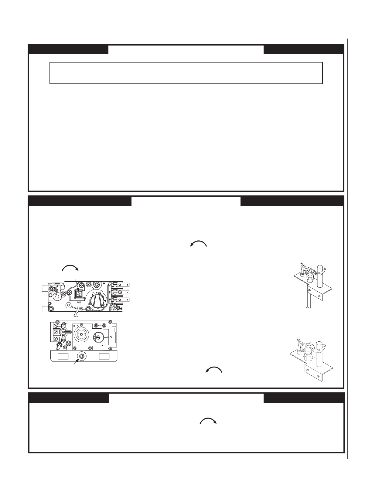
LIGHTING INSTRUCTIONS – HONEYWELL AND SIT MILLIVOLT GAS VALVE
FOR YOUR SAFETY READ BEFORE LIGHTING
WARNING: IF YOU DO NOT FOLLOW THESE INSTRUCTIONS EXACTLY, A FIRE OR EXPLOSION
MAY RESULT CAUSING PROPERTY DAMAGE, PERSONAL INJURY OR LOSS OF LIFE.
A. This appliance has a pilot which must be lighted with a piezo
igniter. When lighting the pilot, follow these instructions
exactly.
B. BEFORE OPERATING smell all around the appliance area for
gas. Be sure to smell next to the fl oor because some gas is
heavier than air and will settle on the fl oor.
WHAT TO DO IF YOU SMELL GAS
• Extinguish any open fl ame.
• Open windows.
• Do not light any appliance.
• Do not touch any electrical switches.
LIGHTING INSTRUCTIONS
1. STOP! Read the safety information above on this Page.
2. Access the lower control compartment.
3. Turn remote wall switch to “OFF.”
4. Verify main line shut-off valve is open.
5. Push in gas control knob slightly and turn clockwise
to “OFF.”
IGNITER
F
T
F
O
O
L
H
I
O
L
I
P
N
O
HONEYWELL
MILLIVOLT
GAS VALVE
IN
T
P
HT
T
TP
H
L
P
I
L
O
T
OUT
I
H
F
F
O
P
I
L
O
ti
W
O
T
O
N
SIT
MILLIVOLT
GAS VALVE
6. Wait fi ve (5) minutes to clear out any gas. If you then smell gas,
7. Push in gas control knob slightly and turn counterclockwise
8. Push in control knob all the way and hold in.
• Do not use any phone in your building.
• Immediately call your gas supplier from a neighbor’s
phone.
• If your gas supplier cannot be reached, call the fi re department.
C. Use only your hand to push in or turn the gas control knob.
Never use tools. If the knob will not push in or turn by hand,
do not try to repair it, call a qualifi ed service technician. Force
or attempted repair may result in a fi re or an explosion.
D. Do not use this appliance if any part has been under water.
Immediately call a qualifi ed service technician to inspect the
appliance and to replace any part of the control system and
any gas control which has been under water.
STOP! Follow “B” in the safety information above on this Page. If you
do not smell gas, go to the next step.
to “PILOT.”
HONEYWELL
MILLIVOLT PILOT
Immediately light the pilot by triggering the
spark igniter (pushing the button) until pilot
lights. Continue to hold the control knob in
for about 1 minutes after the pilot is lit.
Release knob and it will pop back up. Pilot
should remain lit. If it goes out, repeat steps 5
through 8.
• If knob does not pop up when released,
stop and immediately call your service
technician or gas supplier.
SIT
MILLIVOLT PILOT
• If pilot will not stay lit after several tries,
turn the control knob to “OFF” and call
your service technician or gas supplier.
IGNITER
Note: Knob cannot be turned from “PILOT” to “OFF”
unless the knob is pushed in slightly. Do not force.
TO TURN OFF GAS TO APPLIANCE
1. Turn remote wall switch “OFF.” The pilot will remain lit for
normal service.
2. For complete shutdown, turn remote wall switch to “OFF.”
3. Access the lower control compartment.
9. Turn gas control knob counterclockwise
to “ON.”
10. Close lower control compartment.
4. Depress gas control knob slightly and turn clockwise
to “OFF.” Do not force.
5. Close lower control compartment.
17
Page 18
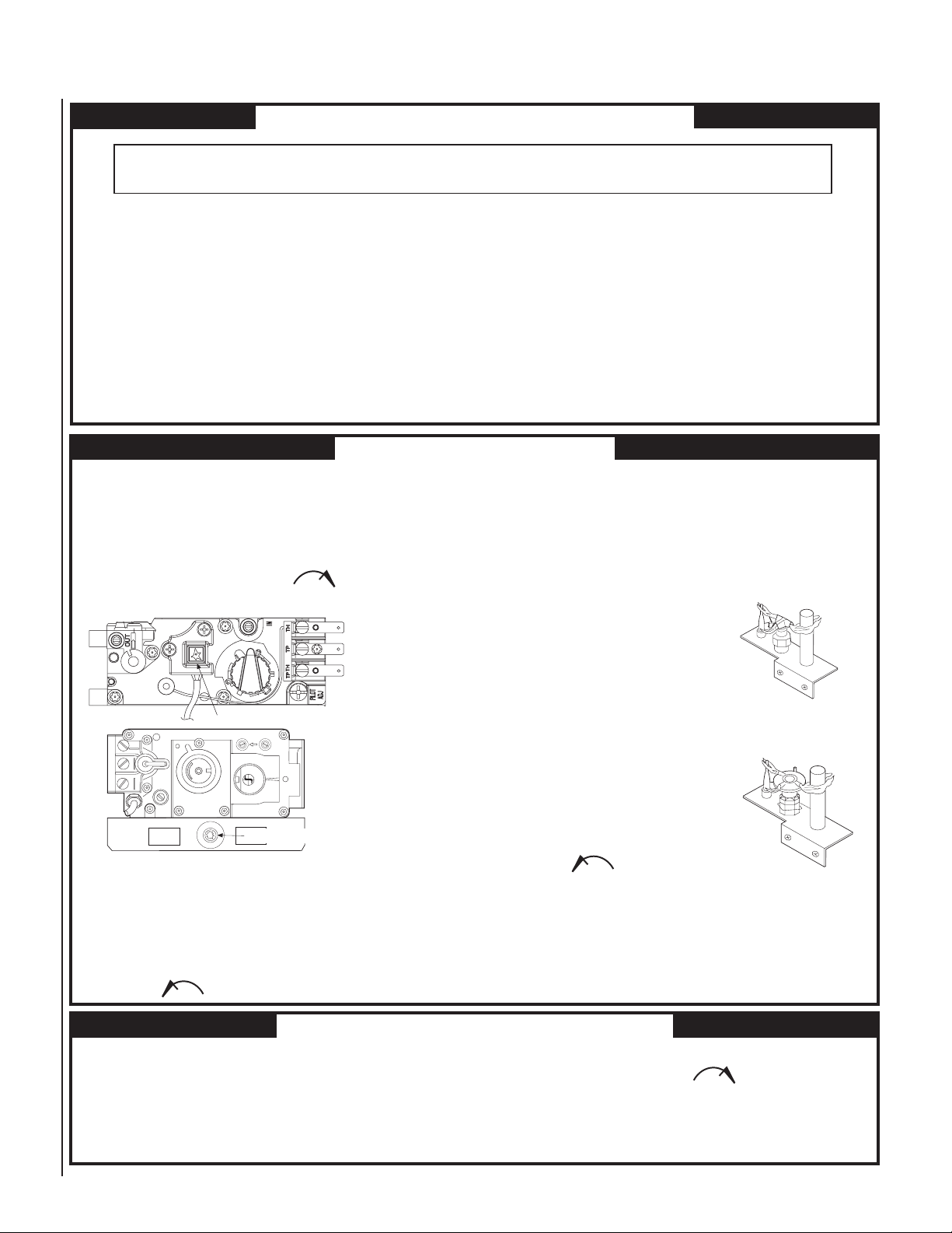
INSTRUCTIONS D’ALLUMAGE – VANNE GAZ MILLIVOLT HONEYWELL ET SIT
POUR VOTRE SÉCURITÉ, LISEZ CES INSTRUCTIONS AVANT L’ALLUMAGE
AVERTISSEMENT : SI VOUS NE SUIVEZ PAS CES INSTRUCTIONS À LA LETTRE, IL POURRAIT S’EN SUIVRE UN INCENDIE OU UNE
EXPLOSION CAUSANT DES DOMMAGES MATÉRIELS, DES BLESSURES CORPORELLES OU MÊME DES PERTES DE VIE.
A. Cet appareil est muni d’une veilleuse qui doit être allumée avec un
allumeur piézo-électrique. Lorsque vous allumez la veilleuse, suivre
exactement ces instructions.
B. AVANT L’ALLUMAGE: Assurez-vous que vous ne détectez aucune
odeur de gaz autour de l’apareil ainsi que près du sol; certains gaz, étant
plus lourds que l’air, descendent au niveau du sol.
VOICI CE QUE VOUS DEVEZ FAIRE SI VOUS DÉCELEZ UNE ODEUR
DE GAZ:
• Éteignez toute flamme visible.
• Ouvrez les fenêtres.
• N’allumez aucun appareil.
• Ne touchez à aucun commutateur électrique.
• Ne vous servez d’aucun téléphone dans votre édifice.
INSTRUCTIONS D'ALLUMAGE
1. ARRÊTEZ! Lisez les consignes de sécurité au verso de cette plaque.
2. Ouvrez le compartiment de contrôle du bas.
3. Tournez l’interrupteur mural à la position d’arrêt “OFF”.
4. Assurez-vous que la soupape d’arrêt de la canalisation principale est
ouverte.
5. Enfoncez légèrement le bouton de réglage du gaz et tournez-le dans
le sens des aiguilles d’une montre jusqu’à la position
d’arrêt “OFF”.
F
T
F
O
O
L
N
O
PIEZO-ELECTRIQUE
I
H
L
W
O
I
P
IN
OUT
F
F
O
P
I
L
i
O
t
T
O
N
H
I
O
L
T
P
T
H
TPT
H
P
I
L
O
T
VANNE GAZ
MILLIVOLT
HONEYWELL
VANNE GAZ
MILLIVOLT SIT
• Appelez immédiatement votre compagnie de gaz en utilisant le téléphone
du voisin.
• S’il vous est impossible de contacter votre compagnie de gaz, appelez
le service des incendies.
C. N’utilisez que votre main pour manipuler le bouton de réglage du gaz.
N’utilisez jamais d’outils. Si le bouton refuse de tourner ou de bouger,
n’essayez pas de le réparer. Communiquez immédiatement avec un
technicien de service qualifié. Toute tentative pour le forcer ou le
réparer, risquerait de provoquer un incendie ou une explosion.
D. Ne vous servez pas de cet appareil si l’un de ses éléments a été
immergé dans l’eau. Appelez immédiatement un technicien compétent
pour faire inspecter l’appareil et remplacer toute pièce du système de
réglage ou commande du gaz qui a été sous l’eau.
8. Enfoncez le bouton de réglage jusqu’au fond et gardez-le enfoncé.
Allumez immédiatement la veilleuse en déclenchant l’allume-gaz à
étincelle (en poussant le bouton) jusqu’à ce que la veilleuse
s’enflamme. Continuez de tenir le bouton de réglage enfoncé
pendant environ 90 secondes après l’allumage de la veilleuse.
Relâchez le bouton et il sortira
subitement. La veilleuse devrait rester
allumée. Si elle s’éteint, répétez les
étapes 5 à 8 inclusivement.
HONEYWELL
MILLIVOLT PILOT
• Si le bouton ne sort pas
automatiquement après avoir été
relâché, arrêtez immédiatement et
téléphonez à votre technicien de
service ou à votre fournisseur de gaz.
• Si la veilleuse refuse de rester allumée
après plusieurs tentatives, tournez le
bouton de réglage jusqu’à sa position
SIT
MILLIVOLT PILOT
d’arrêt “OFF” et téléphonez à votre
technicien de service ou à votre
fournisseur de gaz.
PIEZO-ELECTRIQUE
Remarque: Il est impossible de tourner le bouton de “PILOT” à “OFF” à
moins qu’il ne soit légèrement enfoncé. Ne le forcez pas.
6. Attendez cinq (5) minutes pour l’evacuation du gaz. Si vous décelez
une odeur de gaz, ARRÊTEZ ! Retournez au point “B” des consignes
de sécurité au verso de cette plaque. Si vous ne remarquez aucune
odeur de gaz, passez à l’étape suivante.
7. Enfoncez légèrement le bouton de réglage du gaz et tournez-le en
sens inverse des aiguilles d’une montre jusqu’à la position de
veilleuse “PILOT”.
POUR FERMER LE GAZ QUI ALIMENTE L’APPAREIL
1. Tournez l’interrupteur mural à la position d’arrêt “OFF”. La veilleuse
restera allumée jusqu’au retour du service normal.
2. Pour une fermeture complète, tournez l’interrupteur mural à la
position d’arrêt “OFF”.
3. Ouvrez le compartiment de contrôle du bas.
18
9. Tournez le bouton de réglage du gaz en
sens inverse des aiguilles d’une
montre jusqu’à sa position
de marche “ON”.
10. Fermez le compartiment de contrôle du bas.
11. Au besoin, rebrancher l’appareil au courant électrique et remettre
l’interrupteur du brûleur principal à la position “ON” ou régler le
thermostat à la température désirée.
12. Si l’appareil ne fonctionne pas, suivre les instructions intitulées
“Pour fermer le gaz qui alimente l’appareil” et appeler un
technicien ou le fournisseur de gaz.
4. Enfoncez légèrement le bouton de réglage du gaz et tournez-le dans
le sens des aiguilles d’une montre jusqu’à la position
d’arrêt “OFF”. Ne forcez pas le bouton.
5. Fermez le compartiment de contrôle du bas.
NOTE: DIAGRAMS & ILLUSTRATIONS NOT TO SCALE.
NOTE: DIAGRAMS & ILLUSTRATIONS NOT TO SCALE.
Page 19
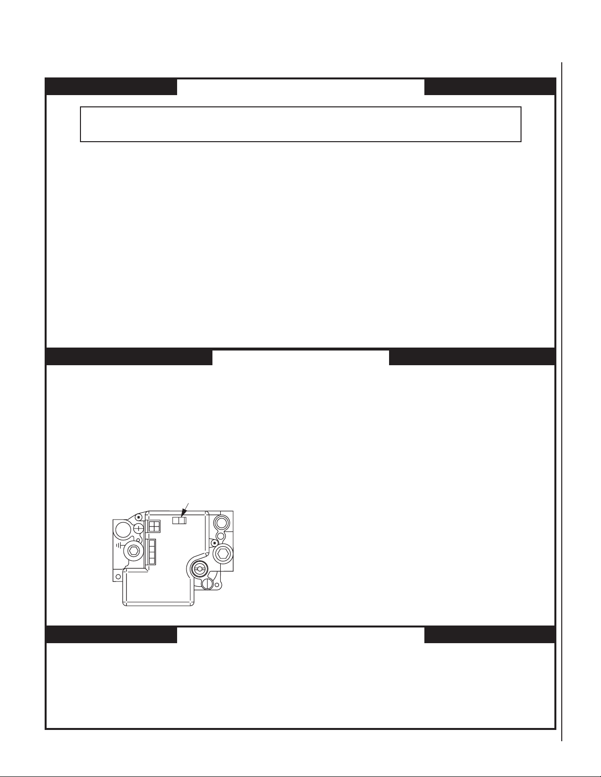
LIGHTING INSTRUCTIONS — ELECTRONIC
FOR YOUR SAFETY READ BEFORE LIGHTING
WARNING: IF YOU DO NOT FOLLOW THESE INSTRUCTIONS EXACTLY, A FIRE OR EXPLOSION
MAY RESULT CAUSING PROPERTY DAMAGE, PERSONAL INJURY OR LOSS OF LIFE.
A. When lighting the appliance, follow these instructions
exactly.
B. BEFORE OPERATING smell all around the appliance area
for gas. Be sure to smell next to the fl oor because some
gas is heavier than air and will settle on the fl oor.
WHAT TO DO IF YOU SMELL GAS
• Extinguish any open fl ame.
• Open windows.
• Do not light any appliance.
• Do not touch any electrical switches.
• Do not use any phone in your building.
LIGHTING INSTRUCTIONS
1. STOP! Read the safety information above on this Page.
2. Turn remote wall switch to “OFF.”
3. Open lower control compartment door.
4. Verify main line shut-off valve is open.
Honeywell Electronic Gas Control Valve
ON / OFF Switch
C
RTNO
NO
O
FFO
L
I
G
N
I
T
ER
Front View
NI
I
PS
• Immediately call your gas supplier from a neighbor’s
phone.
• If your gas supplier cannot be reached, call the fi re
department.
C. Use only your hand to turn the gas control lever. Never
use tools. If the lever will not turn by hand, do not try
to repair it, call a qualifi ed service technician. Force or
attempted repair may result in a fi re or an explosion.
D. Do not use this appliance if any part has been under
water. Immediately call a qualifi ed service technician
to inspect the appliance and to replace any part of the
control system and any gas control which has been under
water.
5. Turn the OFF/ON switch to “OFF”. Do not force.
6. Wait fi ve (5) minutes to clear out any gas. If you then
smell gas, STOP! Follow “B” in the safety information
above on this Page. If you do not smell gas, go to the
next step.
7. Turn the OFF/ON switch to “ON”. Do not force.
8. Turn “ON” all electrical power to appliance (remote wall
or appliance switch).
9. Close lower control compartment door.
TO SHUT OFF
1. Turn off all electrical power to the appliance (remote wall
switch).
TO TURN OFF GAS TO APPLIANCE
1. For complete shut-down, turn remote wall switch to
“OFF.”
2. Open lower control compartment door.
NOTE: DIAGRAMS & ILLUSTRATIONS NOT TO SCALE.
3. Turn the OFF/ON switch to “OFF”. Do not force.
4. Close the main line shut-off valve.
5. Close lower control compartment door.
19
Page 20
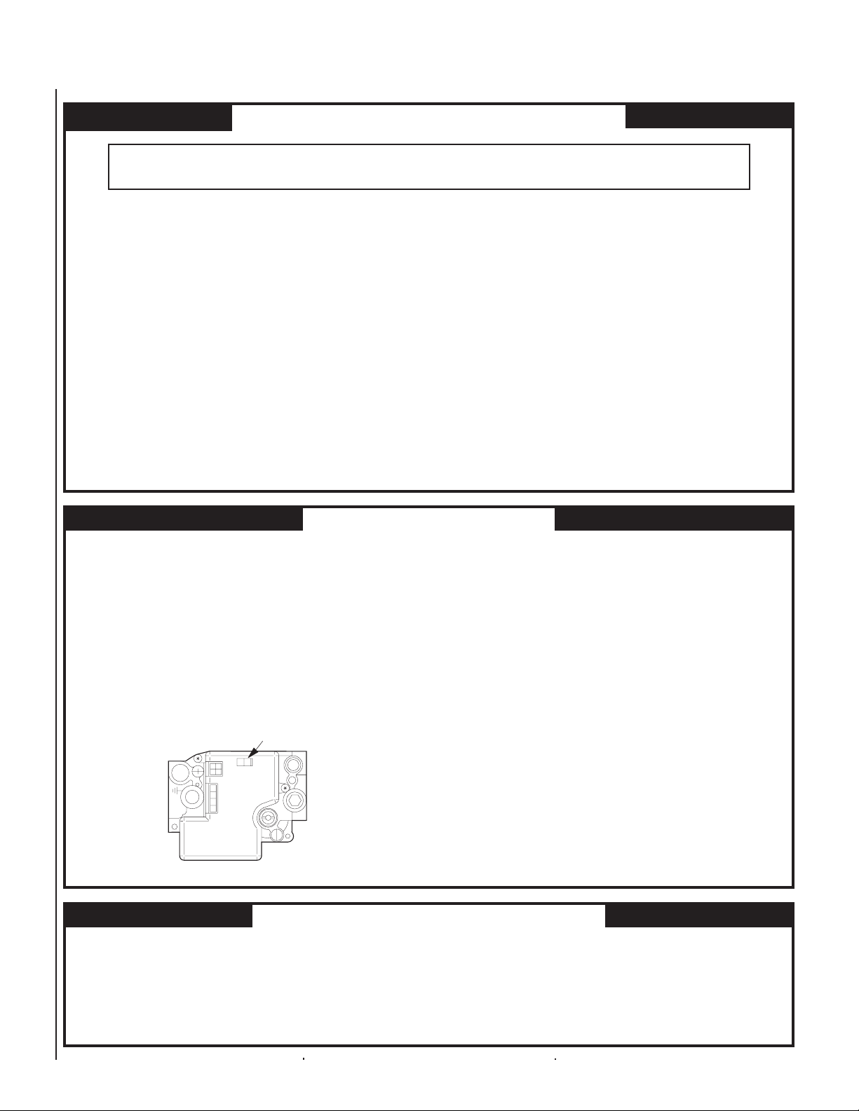
INSTRUCTIONS D’ALLUMAGE — ELECTRONIC
POUR VOTRE SÉCURITÉ, LISEZ CES INSTRUCTIONS AVANT L’ALLUMAGE
AVERTISSEMENT: SI VOUS NE SUIVEZ PAS CES INSTRUCTIONS À LA LETTRE, IL POURRAIT S’EN SUIVRE UN INCENDIE OU
UNE EXPLOSION CAUSANT DES DOMMAGES MATÉRIELS, DES BLESSURES CORPORELLES OU MÊME DES PERTES DE VIE.
A. Lorsque vous allumez l’appareil, suivez exactement ces instruc-
tions.
B. AVANT L’ALLUMAGE: Assurez-vous que vous ne détectez
aucune odeur de gaz autour de l’apareil ainsi que près du sol;
certains gaz, étant plus lourds que l’air, descendent au niveau du
sol.
VOICI CE QUE VOUS DEVEZ FAIRE SI VOUS DÉCELEZ UNE
ODEUR DE GAZ
• Éteignez toute flamme visible.
• Ouvrez les fenêtres.
• N’allumez aucun appareil.
• Ne touchez à aucun commutateur électrique.
• Ne vous servez d’aucun téléphone dans votre édifice.
INSTRUCTIONS D’ALLUMAGE
1. ARRÊTEZ ! Lisez les consignes de sécurité au verso de cette
plaque.
2. Tournez l’interrupteur mural à la position d’arrêt “OFF”.
3. Ouvrez la porte du compartiment de contrôle du bas.
4. Assurez-vous que la soupape d’arrêt de la canalisation principale
est ouverte.
• Appelez immédiatement votre compagnie de gaz en utilisant
le téléphone du voisin.
• S’il vous est impossible de contacter votre compagnie de
gaz, appelez le service des incendies.
C. N’utilisez que votre main pour manipuler linterrupteur “ON/
OFF” de la valve à gaz. N’utilisez jamais d’outils. Si
l’interrupteur ne bouge pas manuellement, n’essayez pas de le
réparer. Communiquez immèdiatement avec un technicien de
service qualifié. Toute tentative pour forcer l’interrupteur ou le
réparer, risquerait de provoquer un incendie ou une explosion.
D. Ne vous servez pas de cet appareil si l’un de ses éléments a été
immergé dans l’eau. Appelez immédiatement un technicien
compétent pour faire inspecter l’appareil et remplacer toute
pièce du système de réglage ou commande du gaz qui a été sous
l’eau.
6. Attendez cinq (5) minutes pour l’evacuation du gaz. Si vous
décelez une odeur de gaz ARRÊTEZ ! Retournez au point “B” des
consignes de sécurité au verso de cette plaque. Si vous ne
remarquez aucune odeur de gaz, passez à l’étape suivante.
7. Tournez la manette de réglage du gaz jusqu’à la position de marche
“ON”. Ne la forcez pas.
8. Ouvrez le courant électrique (“ON”) qui alimente l’appareil
(interrupteur mural).
5. Tournez la manette de réglage du gaz à la position d’arrêt “OFF”.
Interrupteur
/OFF
ON
C
O
N
O
O
RT
F
N
O
F
Vue
L
I
G
TIN
E
R
de face
NI
ISP
POUR FERMER LE GAZ QUI ALIMENTE L’APPAREIL
1. Pour une fermeture complète, tournez l’interrupteur mural à la
position d’arrêt “OFF”.
2. Ouvrez la porte du compartiment de contrôle du bas.
20
9. Fermez la porte du compartiment de contrôle du bas.
10. Au besoin, rebrancher l’apareil au courant électrique et
remettre l’interrupteur principal du brûleur à la position “ON”
ou régler le thermostat à la température désirée.
11. Si l’appareil ne se met pas en marche, suivre les instructions
intitulées “Pour fermer le gaz qui alimente l’appareil” et appeler
un technicien ou le fournisseur de gaz.
POUR ÉTEINDRE L’APPAREIL
1. Coupez tout le courant électrique qui alimente l’appareil (interrupteur
mural).
3. Tournez la manette de réglage du gaz à la position d’arrêt “OFF”.
Ne la forcez pas.
4. Fermez la soupape d’arrêt de la canalisation principale.
5. Fermez la porte du compartiment de contrôle du bas.
NOTE: DIAGRAMS & ILLUSTRATIONS NOT TO SCALE.
NOTE: DIAGRAMS & ILLUSTRATIONS NOT TO SCALE.
Page 21

MAINTENANCE SCHEDULE
Annually (Before the onset of the Burning Season)
MAINTENANCE TASK ACCOMPLISHING PERSON PROCEDURE
Inspecting/Cleaning Burner, Logs
and Controls
Check Flame Patterns and Flame
Height
Inspecting/Cleaning Pilot and Burner Qualifi ed Service Technician
Checking Vent System Qualifi ed Service Technician Inspect the vent system at the top and at the base (within the
Appliance Checkout Qualifi ed Service Technician Perform the appropriate appliance checkout procedure detailed
Qualifi ed Service Technician Inspect valve and ensure it is properly operating. Check piping
for leaks. Vacuum the control compartment, fi replace logs and
burner area.
Qualifi ed Service Technician
Refer to Figure 10 on Page 11 and verify the fl ame pattern
and height displayed by the appliance conforms to the picture.
Flames must not impinge on the logs. Ensure fl ames are steady
(not lifting or fl oating).
Refer to Figure 12 (SIT Millivolt), Figure 13 (Honeywell Millivolt)
or Figure 14 (Electronic) on Page 12. Remove any surface
build-up on pilot and burner assembly. Wipe the pilot nozzles,
igniter/fl ame rod and hood. Ensure the pilot fl ame engulfs the
fl ame sensor as shown.
fi rebox) for signs of blockage or obstruction. Look for any signs
of dislocation or deterioration of the vent components. Note:
Excessive condensation can cause corrosion of caps, pipe &
fi ttings (excessive condensation can be caused by long lateral
runs, too many elbows and/or exterior portions of the system
being exposed to cold weather). Also inspect wall straps or
plumbers's tape to ensure it is secure and in place.
in this manual.
Replacing Rockwool Ember Materials Homeowner/Qualifi ed Service
Technician
Periodically (After the Burning Season)
Remove old ember materials (rockwool) and vacuum the ember
placement area. Place new embers as described and shown in
Figures 8 & 9.
MAINTENANCE TASK ACCOMPLISHING PERSON PROCEDURE
Cleaning Firebox Interior Homeowner Carefully remove logs, rockwool and volcanic stone. Vacuum
out interior of the fi rebox. Clean fi rebox walls and log grate.
Replace logs, rockwool, and volcanic stone as detailed in this
manual.
Check Flame Patterns and Flame
Height
Checking Vent System Homeowner Inspect the vent system at the top and at the base (within the
Cleaning Front Glass Enclosure Panel Homeowner Clean as necessary following the directions provided in this
Homeowner
Refer to Figure 10 on Page 11 and verify the fl ame pattern
and height displayed by the appliance conforms to the picture.
Flames must not impinge on the logs.
fi rebox) for signs of blockage or obstruction. Look for any signs
of dislocation of the vent components.
manual. DO NOT TOUCH OR ATTEMPT TO CLEAN GLASS
WHILE HOT.
NOTE: DIAGRAMS & ILLUSTRATIONS NOT TO SCALE.
21
Page 22

s
s
s
TROUBLESHOOTING
Note: Before troubleshooting the gas control system, Ensure external gas shut off valve, located at gas supply inlet, (and wall switch, iff applicable), is
in the “ON” position.
Important: Valve system troubleshooting should only be accomplished by a qualifi ed service technician.
TROUBLESHOOTING GUIDE - MILLIVOLT GAS CONTROL SYSTEM
SYMPTOM POSSIBLE CAUSES CORRECTIVE ACTION
1. Spark igniter will not light pilot after
repeated triggering of igniter button.
WARNING: if the pilot will not light
after 1 minute of attempting, wait
for at least 5 minutes for gas to
clear before attempting again.
2. Pilot will not stay lit after
carefully following the lighting
instructions.
3. Pilot burning, no gas to burner, Valve
knob “ON,” and the (standard) burner
OFF/ON switch is “ON." Read important note below.
IMPORTANT NOTE: If an optional
*remote switch is used for burner
operation, if the standard burner
OFF/ON switch is still installed on
appliance it must be in the "OFF"
position.
*Optional remote switch kits - wall
switch, wall thermostat or remote
control.
4. Frequent pilot/burner outage prob-
lem.
A. Defective igniter
(no spark at electrode).
B. Defective or misaligned electrode at pilot
(spark at electrode).
C. Gas supply pressure errant.
D. Pilot orifi ce plugged.
A. Defective pilot generator
(thermocouple).
A. Wall switch or wires defective.
B. Thermopile may not be generating suf-
fi cient millivolts.
C. Plugged burner orifi ce.
D. OFF/ON Switch & *Remote Switch are in
the "ON" position resulting in excessive
resistance.
A. Pilot fl ame may be too low or blowing (high)
causing the pilot/valve safety to drop out.
Check for spark at electrode and pilot; if no spark and
electrode wire is properly connected, replace igniter.
Using a match, light pilot. If pilot lights, turn off pilot
and trigger the igniter button again. If pilot lights, an
improper gas mixture caused the bad lighting and a
longer purge period is recommended. If pilot will not
light – check gap at electrode and pilot – should be 1/8"
to have a strong spark. If gap measures 1/8", replace
pilot (see Figure
Check inlet gas pressure. It should be within the limits
as marked on the rating plate.
Clean or replace pilot orifi ce.
Check pilot fl ame, it must impinge on thermocouple
(see Figure
adjust pilot for maximum fl ame impingement on
thermocouple. Ensure that the connection between
the valve and thermocouple are tight and secure.
Check wall switch and wires for proper connections.
Jumper wire across terminals at wall switch, if burner
comes on, replace defective wall switch. If okay, jumper
wires across wall switch wires at valve, if burner comes
on, wires are faulty or connections are bad.
Check thermopile with millivolt meter. Take reading
at thermopile terminals of gas valve. Should read
325 millivolts minimum with optional wall switch
“OFF.” Replace faulty thermopile if reading is below
specifi ed minimum.
Check burner orifi ce for blockage and remove.
When turning on the burner using a *remote switch,
ensure that the standard OFF/ON switch is in the "OFF"
position. If both switches are in the ON position, it
may result in excessive resistance (& millivolt drainage) and the burner may not come on.
Clean and/or adjust pilot fl ame for maximum fl ame
impingement on thermocouple (see Figure
13 on Page 12).
12 or 13 on Page 12).
12 or 13 on Page 12). Clean and/or
12 or
TROUBLESHOOTING GUIDE - ELECTRONIC IGNITION SYSTEM
SYMPTOM POSSIBLE CAUSES CORRECTIVE ACTION
1. Burner will not light. A. Faulty Valve System.
B. “OFF/ON” or wall switch defective.
2. Burners come “ON,” then turns “OFF.” A. Burner orifi ce plugged.
B. Obstructed vent system.
22
NOTE: DIAGRAMS & ILLUSTRATIONS NOT TO SCALE.
See Below.
Disconnect the two black wires from the wire nuts.
Test switch(s) for continuity with a multimeter. If
continuity is not indicated, switch(s) is defective and
must be replaced.
Note: Before replacing “OFF/ON” switch, Ensure to
check wiring for loose connections or broken wires
and repair as needed.
Check main burner orifi ce(s) for blockage. Clean
or replace.
Check vent system for obstructions.
Page 23
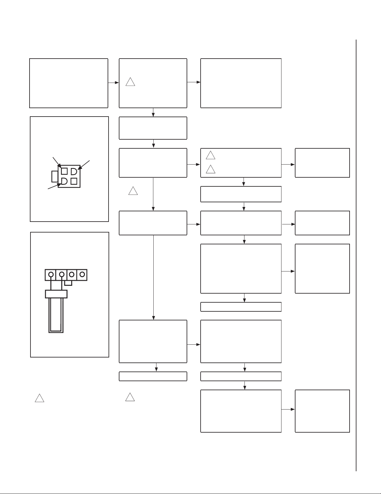
TROUBLESHOOTING PROCEDURE - ELECTRONIC IGNITION SYSTEM
START CHECK
• Turn Off Gas Supply.
• Ensure Valve Switch Is In ON Position.
• Disconnect Control Harness.
• Set Thermostat To Call For Heat.
Insert A
End View of Control Harness Connector
• Check for proper voltage at control harness
(see insert A). Voltage
2
should be 24V between
thermostat or pressure
switch and 24V common
and 24V hot.
YES
• Plug control harness into
valve. Wait for internal check
delay.
NO
• Line voltage power
• Low voltage transformer
• Limit controller
• Thermostat
• Wiring
24 Volt Hot
24 Volt
Common
24 Volt
Switched
Check For Damaged or Missing
Terminals in Connector
Insert B
Igniter Terminals
• With pilot burner cable con-
1
• Igniter warms up and glows
red.
NO
nected, measure voltage at
valve HSI element output. 24V
2
nominal. (See insert B)
YES
YES • Replace igniter/fl ame rod
1
assembly.
YES
• Check that pilot gas is fl owing. Wait
• Turn on gas supply.
• Pilot burner lights.
NO
to ensure pilot gas tubing is purged.
Recycle call for heat if necessary.
YES
• Measure voltage between 24V hot and
24V common leads to valve control.
Must measure at least 19.5 VAC with
igniter powered (see insert A). To
YES
identify proper lead, this check must
be done with the valve control connected and igniter powered.
YES
• Replace Pilot Assembly.
• Check that pilot fl ame makes good
contact with pilot burner fl ame rod.
• Main valve opens and main
burner lights.
• Check for good electrical connection
NO
through the pilot tubing.
• If both of the above are good, replace
igniter/fl ame rod assembly.
YES YES
• System Is okay. • Cycle thermostat off and back on.
NO
• Replace valve.
NO
• Replace valve.
• Check transformer and
NO
line volt supply.
Igniter will cycle off and
1
back on once during the 90
second ignition trial. All
voltage measurements must
be taken while the igniter is
powered.
When measuring voltage
2
at connections, use care
to ensure terminals are
not damaged.
NOTE: DIAGRAMS & ILLUSTRATIONS NOT TO SCALE.
• Main burner lights.
NO
• Replace valve.
23
Page 24
REPLACEMENT PARTS LIST
Item # Description SSDV-3530 SSDV-4035
Part No. Qty. Part No. Qty.
1 Hood, Charcoal 97K51 1 97K52 1
2 Louver Assembly, Top, Charcoal
3 * Louver Assembly, Bottom, Charcoal
4 Enclosure, Glass Front (Complete)
5 Nameplate, Superior (logo) 56L93 1 56L93 1
6 Latch 69L21 2 69L21 2
7 Log Set (Complete) H3367 1 H3368 1
8 Burner Assembly 69L09 1 69L10 1
9 Burner Bracket LB-92357 1 LB-92357 1
10 Ember Screen LB-92438B 1 LB-92438C 1
11 Orifi ce, Main Burner - Natural Gas 69L09 1 18L40 1
11 Orifi ce, Main Burner - Propane Gas 99K79 1 37G00 1
12 Bag of Glowing Embers (Rockwool) 88L53 1 88L53 1
12 Bag of Decorative Volcanic Stone 80L42 1 80L42 1
13 Gas Line Flexible Connector, FFGC 93L32 1 93L32 1
* Superior Nameplate Logo, 56L93, is not included.
H3376
H3379
H4864
1
1
1 H3724 1
H3377
H3380
1
1
Gas Controls - SIT Millivolt
Natural Gas Propane Gas
Part No. Qty. Part No. Qty.
14 Gas Valve, SIT 43K07 1 88J53 1
15 Piezo Igniter 91K94 1 91K94 1
16 Pilot Assembly 69L17 1 69L18 1
17 Pilot Generator 60J79 1 60J79 1
18 Thermocouple 74L57 1 74L57 1
19 Pilot Tube 74L56 1 74L56 1
20 Electrode and Cable 74L58 1 74L58 1
21 Pilot Shield H3737 1 H3737 1
22 Gas Valve, Honeywell 24M12 1 82L87 1
23 Piezo Igniter 24M89 1 24M89 1
24 Pilot Assembly 67L70 1 67L70 1
25 Pilot Generator 60J79 1 60J79 1
26 Thermocouple 67L67 1 67L67 1
27 Pilot Tube 67L68 1 67L68 1
28 Electrode and Cable 67L87 1 67L87 1
29 Pilot Shield H3737 1 H3737 1
Gas Controls - Honeywell Millivolt
Natural Gas Propane Gas
Part No. Qty. Part No. Qty.
Gas Controls - Honeywell Electronic
Natural Gas Propane Gas
Part No. Qty. Part No. Qty.
30 Gas Valve, Honeywell 62L18 1 62L19 1
31 Pilot Assembly 62L14 1 62L15 1
32 Transformer 42J32 1 42J32 1
33 Igniter Assembly (Kit) 87L54 1 87L54 1
34 Pilot Shield H1596 1 H1596 1
24
Page 25
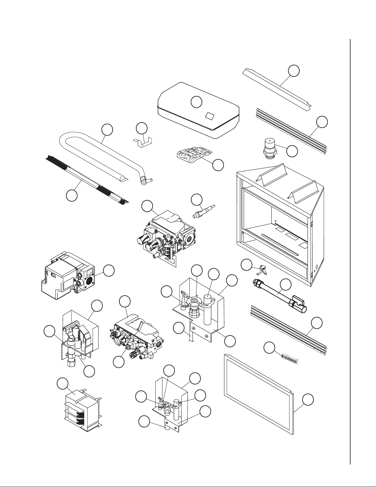
REPLACEMENT PARTS DIAGRAMS
8
1
7
2
9
11
12
31
32
10
33
34
30
23
22
14
18
28
19
29
15
20
17
16
21
6
13
3
5
26
25
27
NOTE: DIAGRAMS & ILLUSTRATIONS NOT TO SCALE.
4
24
25
Page 26

NOTES
26
NOTE: DIAGRAMS & ILLUSTRATIONS NOT TO SCALE.
Page 27

NOTES
NOTE: DIAGRAMS & ILLUSTRATIONS NOT TO SCALE.
27
Page 28

LHP reserves the right to make changes at any time, without notice, in design, materials, specifi cations, prices and also to discontinue colors, styles and products. Consult your local distributor
for fi replace code information.
Printed in U.S.A. © 2005 by LHP
P/N 725,033M REV. D 05/2006
LHP
1110 West Taft Avenue • Orange, CA 92865
 Loading...