

Page 1
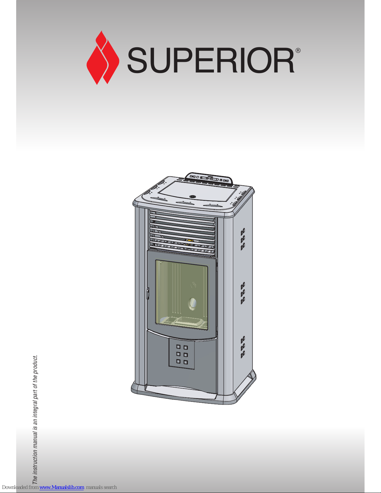
INSTRUCTIONS FOR
INSTALLATION, USE AND
MAINTENANCE
Pellet Stove
SOFIA
The instruction manual is an integral part of the product.
SUPERIOR
®
Page 2
English
2
SUPERIOR
®
Dear client,
We thank you for choosing one of our products, the result of technological expertise and continued research in pursuit of a superior
product in terms of safety, reliability and features.
In this manual you will find all the information and useful advice necessary to get the most out of your appliance in total safety.
DT2010001-01
See the guarantee certificate enclosed with the product for the terms, limitations and exclusions.
In line with its policy of constant product improvement and renewal, the manufacturer may make changes without notice.
This document is the property of Gruppo Piazzetta S.p.A.; no part of it may be disclosed to third parties without the written permission of Gruppo
Piazzetta S.p.A. All rights reserved by Gruppo Piazzetta S.p.A..
• This instruction booklet has been prepared by the manufacturer and is an integral part
of the product. In the event of sale or relocation of the product make sure this booklet
accompanies it, since the information contained in it is intended for the purchaser and
for anyone involved in the installation, use and maintenance of the product.
• Read the instructions and the technical information contained in this booklet carefully
before proceeding with installation, use or any repairs.
• The observance of the instructions and technical information in this instruction booklet
guarantees the safety of persons and property; it also ensures more efficient operation
and an increased lifespan.
• Gruppo Piazzetta S.p.A. cannot be held responsible for damage or injury due to failure
to comply with the instructions for installation, use and maintenance given in this
booklet, or due to unauthorised alterations or to the use of other than original spare
parts.
• Appliance installation and use must conform with the manufacturer’s instructions as
well as with European and national legislation and local regulations.
• Installation, electrical connection, checks, maintenance and repairs are operations
which must be carried out exclusively by qualified and authorised personal with
specialised knowledge of the product.
• The wall against which the product is to be placed must not be of wood or any other
flammable material. For correct installation it is also important to comply with the
section entitled “Safety distances”.
• Before installing the product read all instruction booklets relevant to the cladding, the
ventilation kit and any other accessory.
• Check that the floor where the product is to be installed is perfectly level.
• When handling the steel parts of the cladding it is advisable to use clean cotton gloves
to avoid leaving fingerprints that are difficult to remove at first time of cleaning.
• The stove must be assembled by at least two persons.
• Connect the pellet stove to the electricity supply only after it has been connected by
an expert to the flueway.
• The plug at the end of the power cable must be easily accessible after installation.
• Use only recommended wood pellets in the pellet stove (refer to section entitled “FUEL”).
• Never use liquid fuels to light the pellet stove or to relight the embers.
• Ensure that the area where the stove is installed is properly ventilated while the stove
is lit.
• In the event of malfunctioning the fuel supply will be stopped. Restart the stove only
after having eliminated the cause of the malfunction.
• Stop using the product in the event of fault or malfunctioning.
• Do not remove the protective grille from the pellet hopper.
• Any build-up of unused pellets in the burner left over from repeated failed ignitions
must be removed before attempting to light the stove again.
• Stove operation can result in surfaces, handles, flue pipe and glass becoming
extremely hot. When the stove is in operation, only touch these parts if wearing
protective clothing otherwise use suitable tools.
• Because of the build-up of heat on the glass, take care that those who are unfamiliar
with stove operation do not linger near the stove.
• This appliance must not be used by persons (including children) with reduced physical,
sensory or mental capacities, or lack of experience or knowledge unless they are
supervised or instructed on use of the appliance by the person who is responsible for
its safety.
• Creaking may be heard while the stove is in operation or cooling down. This is not to
be considered a defect, but is a consequence of thermal expansion of the component
materials.
• The product you have purchased may different slightly from the one illustrated in this
booklet since the pictures are only given as an indication and not an exact portrayal.
In the event of difficulties or if you are unable to understand the instruction
booklet, contact your local dealer.
Do not place objects which are not heat-resistant on top of the stove or
within the recommended minimum safety area.
Do not open the door while the stove is in operation or operate the stove
when the glass is broken.
EN 14785 Residential space heating appliances fired by wood pellets. Requirements and test methods
EN 832 Thermal performance of buildings - Calculation of energy use for heating - Residential buildings
UNI 10683 Heat generators fired by wood or other solid biofuels - Installation requirements
UNI 10847 Single flue systems for liquid and solid fuel generators - Maintenance and inspection - Guidelines
and procedures
UNI 7129 Gas installations for domestic use fired by mains gas supply. Design, installation and maintenance.
DIN 51731 class HP2 Fuels
ÖNORM M7135 Fuels
CEI EN 60335-1 Safety of household and similar electrical appliances.
Safety. Part 1: General requirements
CEI EN 50165÷1997 Electrical equipment of non-electric appliances for household and similar purposes – Safety
requirements
EN 1856-1 Chimneys - Requirements for metal chimneys - Part 1: System chimney products
EN 1856-2 Chimneys - Requirements for metal chimneys - Part 2: Metal liners and connecting flue pipes
EN 1443 Chimneys – General requirements
IMPORTANT INFORMATION
DT2010208-07
REFERENCE STANDARDS
DT2010209-05
H07022850 / DT2000426 - 00
Page 3

English
3
SUPERIOR
®
This booklet code H07022850 / DT2000426 Rev. 00 (01/2009) comprises 40 pages.
CONTENTS
DT2010187-00
Section Title Page
1.0 GENERAL RULES 4
1.1 Single flueway or chimney 5
1.2 Soot inspection 5
1.3 Chimney stack 6
1.4 Fresh air intake 7
1.5 Installation environment 7
1.6 Capacity load of the floor 8
1.7 Heating capacity 8
1.8 Minimum safety distances 9
1.9 Flueway 9
1.10 Connecting to a conventional chimney 11
1.11 Using an external flue 12
1.12 Prevention of domestic fires 12
2.0 TECHNICAL CHARACTERISTICS AND SPECIFICATIONS 13
2.1 Features 13
2.2 Technical data 13
2.3 Product identification data 14
2.4 Dimensional diagram 14
2.5 Wiring diagram 15
3.0 FUEL 16
4.0 PREPARING FOR INSTALLATION 16
5.0 INSTALLATION 17
5.1 Electrical connection and the room sensor connection 17
5.2
Installing the external thermostat
17
6.0 USE 18
6.1 Control panel 18
6.2 Lighting for the first time 19
6.3 Startup and normal operation 19
6.4 Remote control 22
6.5 Timer 23
6.6 Safety devices 28
6.7 Opening the door 31
6.8 Disposal of ashes 31
7.0 MAINTENANCE 32
7.1 Cleaning the grate and the grate support 32
7.2 Cleaning the ash drawer 32
7.3 Cleaning the firebox 32
7.4 Cleaning the smoke chamber 33
7.5 Cleaning the flue system 33
7.6 Cleaning the ceramic cladding 33
7.7 Cleaning the enamelled metal parts 33
7.8 Cleaning the glass (DAILY) 34
7.9 Replacing the window 34
7.10 Replacing the remote control battery 34
7.11 Cleaning the fans 34
7.12 When not in use 34
7.13 Extraordinary maintenance 34
8.0 TROUBLESHOOTING 35
8.1 Replacing the fuses 38
Declaration of conformity Pellet Stove Sofia 39
H07022850 / DT2000426 - 00
Page 4
English
4
SUPERIOR
®
DT2030321-00
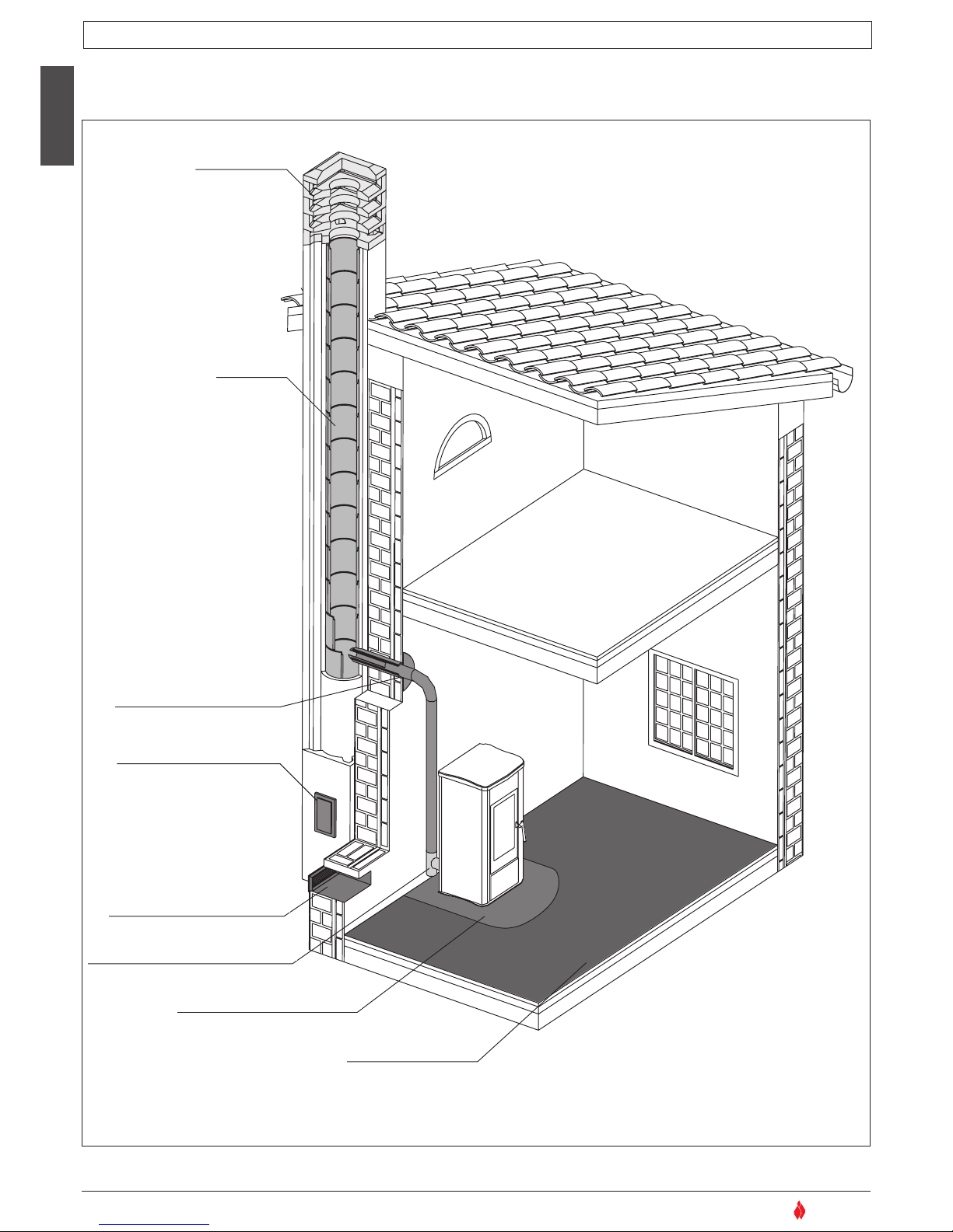
Ensure that the installation of your product conforms to all the indications given below.
Fig. 1
CHIMNEY STACK
SINGLE FLUEWAY
OR CHIMNEY
CONNECTION TO FLUE
SOOT INSPECTION
APERTURE
FRESH AIR INTAKE
MINIMUM SAFETY DISTANCES
CAPACITY LOAD
OF THE FLOOR
END ELBOW WITH
INSPECTION WINDOW
1.0 GENERAL RULES
DT2010216-04
H07022850 / DT2000426 - 00
Page 5
English
5
SUPERIOR
®
NO
X
Minimo 3,5 m
MAX 45°
NO
NO
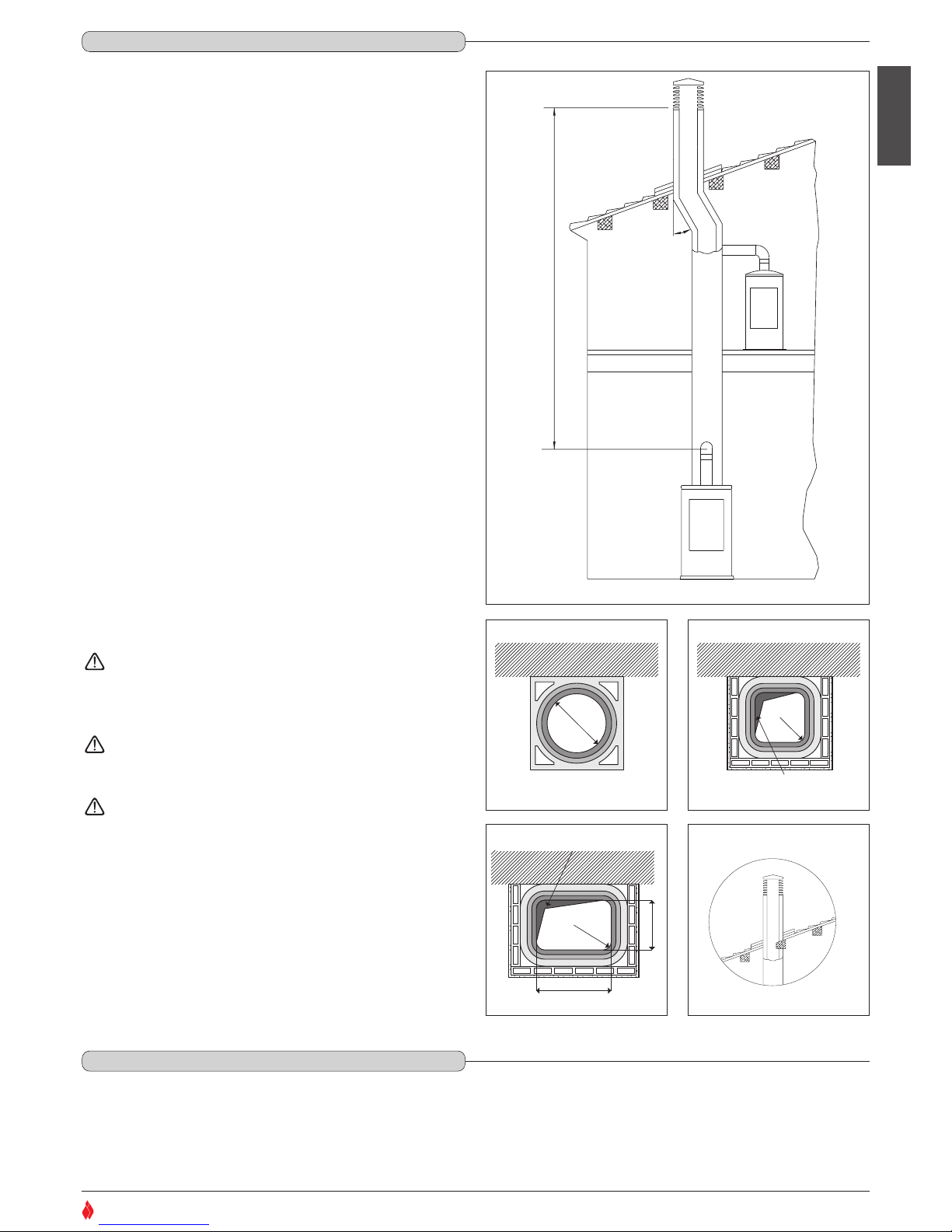
Every appliance must have a vertical flue pipe operating by natural
draught to discharge the combustion gases outdoors.
The flue must:
- comply with regulations in force in the place of installation of the
appliance;
- be tight to the products of combustion, waterproof, suitably insulated,
made with materials resistant to corrosion by the gases and to stress;
- be connected to just one stove, fireplace or extraction hood (Fig. 2);
- be properly sized, with constant free internal section, equal to or
greater than the diameter of the flue pipe of the stove and at least 3.5
m in length (Fig. 2);
- be mainly in a vertical position with a deflection from the axis of no
more than 45° (Fig. 2);
- be at a suitable distance from combustible or flammable materials,
ensured by an air gap or suitable insulating material;
- be of uniform internal section, preferably round. Square or
rectangular sections must have rounded corners with a radius of at
least 20mm and a maximum ratio between the sides of 1.5 (Fig. 3-4-
5). The walls must be smooth if possible and without narrowing.
Bends must be regular and without discontinuity (Fig. 6).
It is forbidden to make fixed or mobile apertures on the flue
pipe to connect appliances other than the one to which it is
already connected.
It is forbidden to pass other air ducts or service pipes inside
the flue pipe, however large it is.
If the flue pipe is an incorrect size or installed other than in
compliance with the above instructions, Gruppo Piazzetta
S.p.A. cannot be held liable for malfunctioning of the product,
damage to property or injury to persons or animals.
Ø
DT2030050-00
DT2030049-00
Fig. 3
P
R (min. 20)
L (≤ 1,5 x P)
Accumulo di Creosoto
DT2030189-00
Fig. 5
R (min. 20)
Accumulo di Creosoto
DT2030188-00
Fig. 4
Fig. 2
DT2030190-00
Fig. 6
3.5 M MINIMUM
Deposit of Creosote
Deposit of Creosote
1.1 SINGLE FLUEWAY OR CHIMNEY - Fig. 2 / 6
DT2010024-02
1.2 SOOT INSPECTION - Fig. 1
DT2010031-01
We recommend that the flue must have a chamber for collecting solid matter and any condensate located below the connection and which may
be easily inspected by means of an airtight door. (Fig.1)
H07022850 / DT2000426 - 00
Page 6
English
6
SUPERIOR
®
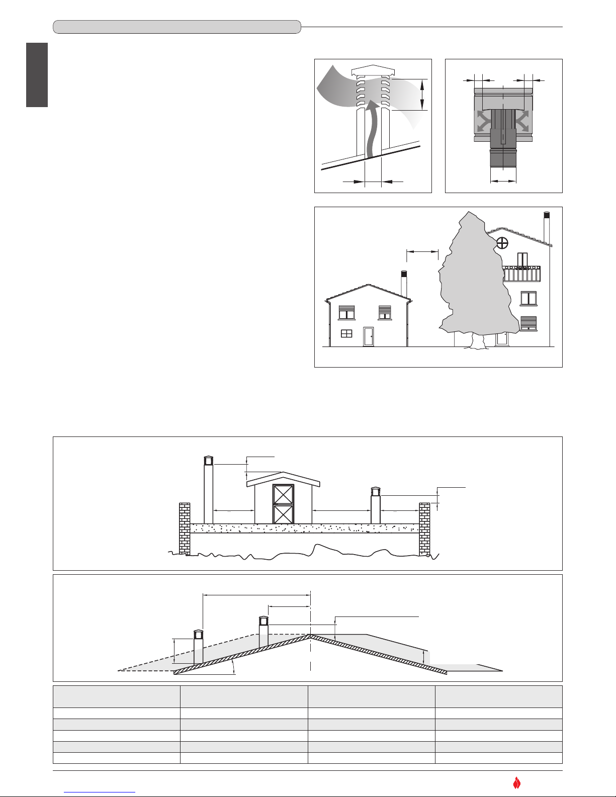
The chimney stack is a device fitted on the top of the chimney that is designed to
aid dispersion of the products of combustion in the atmosphere.
The chimney stack must comply with the following requirements:
- it must have an internal section and shape the same as the flue (A);
- it must have a useful outlet section (B) of not less than twice that of the flue (A);
- the part of the chimney that emerges from the roof or remains in contact with the
outside (e.g. in the case of a flat roof), must be covered with brick or tile elements
and in any case well insulated;
- It must be built in such a way as to prevent the penetration of rain, snow and
foreign matter into the flue and to ensure that in the event of winds from all
directions and angle, discharge of the combustion products is assured (chimney
stack with down-draught cowl).
Recommended distances for correct chimney operation.
To ensure trouble-free operation of the chimney and allow correct dilution of the
products of combustion in the air, the chimney stack must be installed at the
distances given below:
- 6 - 8 metres from any buildings or other obstacles that are higher than the
chimney stack;
- 50 centimetres higher than any obstacles located at a distance less than 5 metres;
- outside the reflux area. The size and shape of this area differ according to the angle
of inclination of the roof and it is therefore necessary to adopt the minimum
heights shown below.
Example: Check the slope of the roof (column
α
), and the anticipated distance of
the chimney stack from the axis of the ridge (column A); if the distance is greater
than “A” the height of the chimney stack may be read in (column H); if the distance
is less than “A” the chimney stack must rise above the ridge by 0.5 metres.
6-8 m
DT2030052-00
Fig. 9
TETTO PIANO
0.50 m
0.50 m
maggiore 5 m
pari o minore
5 m
pari o minore
5 m
DT2030053-00
Fig. 10
TETTO PIANO
TETTO INCLINATO
0.50 m
0.50 m
0.50 m oltre il colmo
altezza zona di
reflusso Z
asse colmo
distanza maggiore A
α
H min.
distanza
min. uguale A
maggiore 5 m
pari o minore
5 m
pari o minore
5 m
Fig. 11
A
B*
* B equivale al
doppio di A
DT2030051-00
Fig. 7
A
B
B
DT2030191-00
Fig. 8
DT2030192-00
* B it is twice
of to A
FLAT ROOF
5 m
or less
5 m
or less
over 5 m
SLOPING ROOF
distance more than A
distance
at least A
ridge axis
0.50 above the ridge
height of
reflux area Z
Pitch of the roof
Horizontal width of reflux
area from ridge axis
Minimum height of
outlet from roof
Height of reflux
area
αα
A H min Z
15° 1,85 m 1,00 m 0,50 m
30° 1,50 m 1,30 m 0,80 m
45° 1,30 m 2,00 m 1,50 m
60° 1,20 m 2,60 m 2,10 m
REFLUX AREA
1.3 CHIMNEY STACK - Fig. 7 / 11
DT2010025-03
H07022850 / DT2000426 - 00
Page 7
English
7
SUPERIOR
®
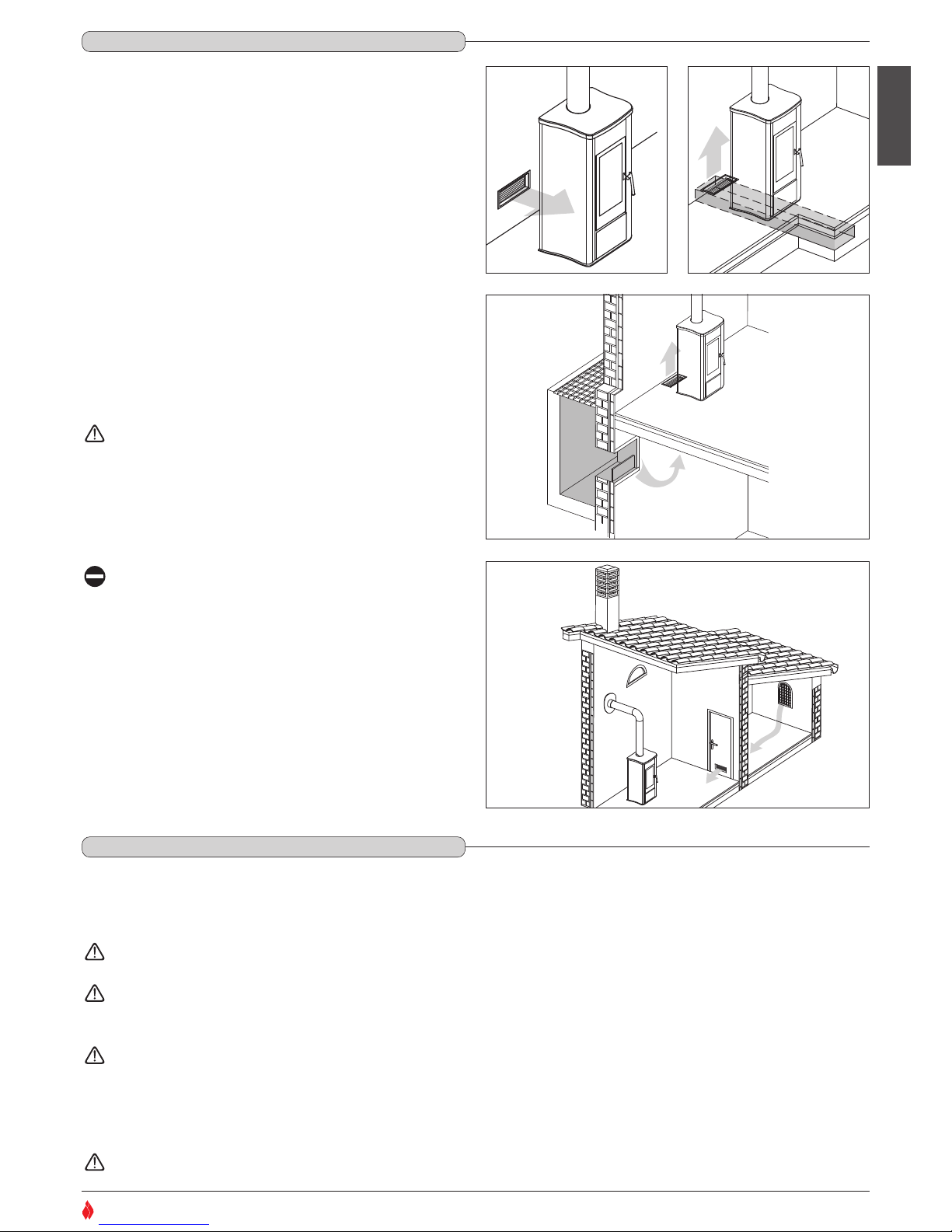
To ensure trouble-free operation the stove/fireplace must have the
necessary air available for combustion and this is provided through the
fresh air intake.
The fresh air intake must:
- have a total free cross section at least equal to the size given in the
paragraph “TECHNICAL DATA”;
- be protected by a grille or suitable guard provided it does not reduce
the minimum recommended section;
- be in a position whereby it cannot be obstructed.
The airflow necessary for the fire may be obtained in different ways:
- through a fresh air intake direct into the room of installation;
- with ducting through pipes direct to the room of installation, increasing
the recommended minimum free cross section by at least 15%;
- from an adjacent room to the place of installation provided this air flows
freely through permanent apertures communicating with the outside.
The adjacent room from which air is taken must not have a low
pressure compared to the exterior due to a counter draught
caused by the presence in that room of another appliance in
use or of a suction device.
The permanent apertures in the adjacent room must comply
with the requirements given above.
Combustion air must not be taken from adjacent rooms used
as a garage or a combustible materials store or for activities
posing a fire hazard.
DT2030054-00
Fig. 12
DT2030194-00
Fig. 14
DT2030195-00
Fig. 15
DT2030193-00
Fig. 13
1.4 FRESH AIR INTAKE - Fig. 12 / 15
DT2010539-03
1.5 INSTALLATION ENVIRONMENT
DT2010033-01
The appliance should be installed in a location which allows safe and convenient use as well as easy maintenance. If the product being installed
requires an electrical socket, the room must also be provided with an earthed power supply in accordance with current regulations.
The room where the appliance is to be installed must comply with the following requirements:
they must not be used as a garage, store for combustible material or for activities with a risk of fire.
They must not be in a vacuum in relation to the outside environment due to the effect of contrary draught caused by the presence in
the room where the fi replace is installed of another appliance or an extractor device.
Do not use two stoves, a fireplace and a stove, a stove and a wood-fired cooking range, etc. in the same environment, since the draught
of one could affect the draught of the other.
- Devices suitable for cooking food with relative hoods without an extractor fan may only be used in kitchens.
- Gas appliances of type C are allowed (refer to current legislation and regulations in the place of installation)
Gas appliances of type B are not allowed (refer to current legislation and regulations in the place of installation)
H07022850 / DT2000426 - 00
Page 8

English
8
SUPERIOR
®
The stove or fireplace must not be used simultaneously with collective type ventilation ducts with or without extractor fan, other devices
or other appliances such as: forced ventilation systems or other heating systems using ventilation to change the air. Such systems could
cause a vacuum in the environment of installation even if installed in adjoining or communicating rooms.
The stove or fireplace must not be used: in stairwells except in buildings with no more than two apartments; in corridors for common
use; in bedrooms; in bathrooms or shower-rooms.
Check the load-bearing capacity of the floor, referring to the weight of the product given in the paragraph “TECHNICAL DATA”.
If the floor does not have a suitable load-bearing capacity, adequate countermeasures must be taken, for example, by using a sheet metal plate to
distribute the load.
Check the heating capacity of the appliance by comparing the rated power given in the paragraph “TECHNICAL DATA” with the power required by the
environment to be heated.
The energy requirement may be calculated approximately by multiplying the square metres of area by the height of the ceiling; the result is then
multiplied by a coefficient, which depends on the degree of insulation of the building, that is, on internal and external factors of the dwelling:
a) Internal factors: type of window and door frames, thickness of the insulation and walls, type of building materials, presence of stairwells, walls with
extensive glazing, high ceilings, position of the rooms to be heated in relation to other adjacent heated or unheated rooms, …
b) External factors: geographical position, average outdoor temperature, exposure, wind speed, latitude, altitude, …
Example of approximate calculation of the energy requirement to heat a fixed volume to 18/20° C:
The coefficient that is normally used is determined according to the real conditions as they occur case by case.
- From 0.04 to 0.05 kW per cubic metre in a well insulated environment
- From 0.05 to 0.06 kW per cubic metre in a poorly insulated environment.
3 rooms measuring 20m2 X (H ceiling) 2.7m = 162 m3 (volume)
In an environment with a good degree of insulation, an average value (coefficient) of 0.045 kW may be taken
162 (volume) X 0.045 (kW) = 7.3 kW necessary (6300 kcal/h)
Conversion 1kW = 860 kcal/h
Consult a heating technician or engineer for a correct check and calculation of the requirement of the environments to be heated (see
“REFERENCE STANDARDS”).
1.6 CAPACITY LOAD OF THE FLOOR
DT2010032-00
1.7 HEATING CAPACITY
DT2010130-01
H07022850 / DT2000426 - 00
Page 9
English
9
SUPERIOR
®
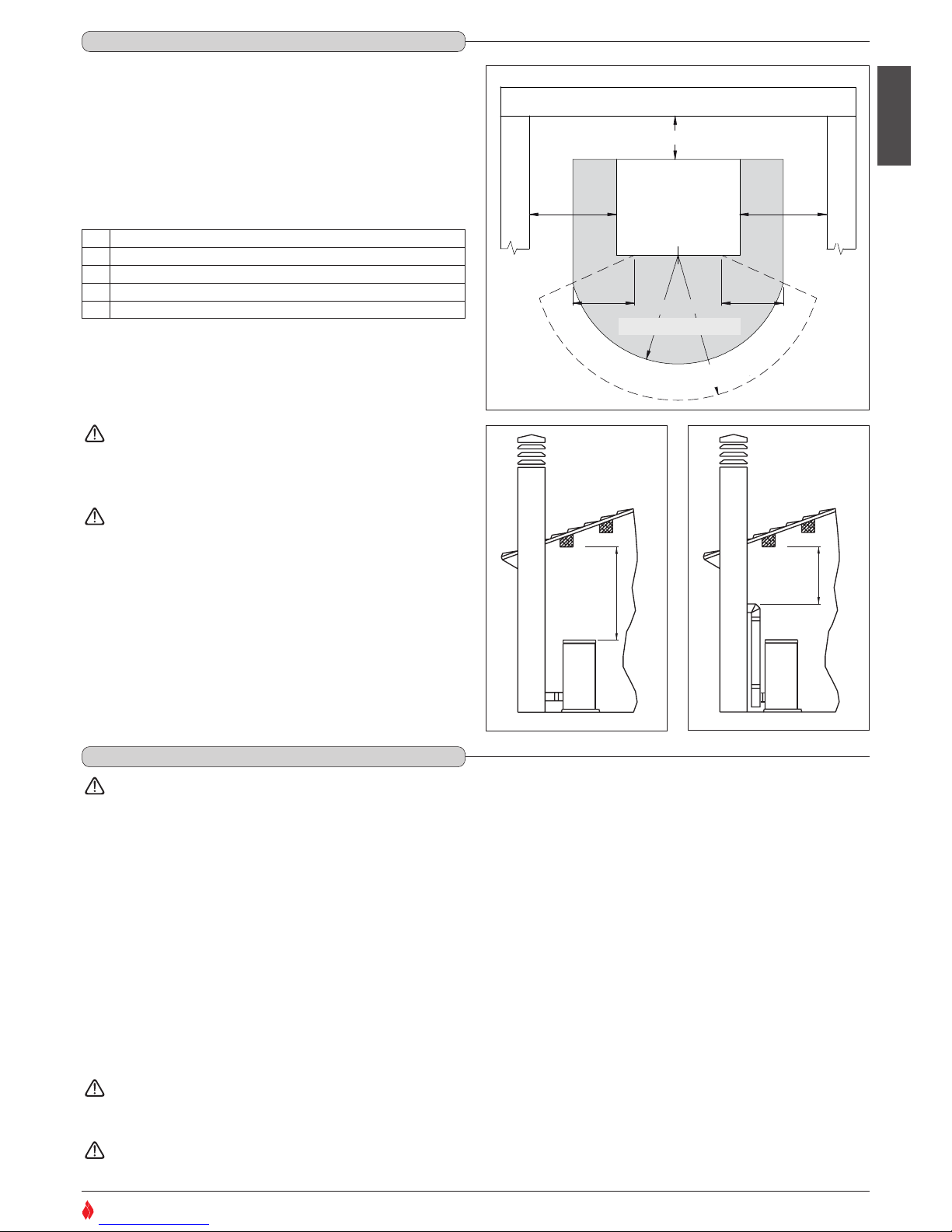
Install the product in compliance with the recommended safety
distances from heat sensitive or inflammable materials, from load
bearing and other walls and also from wooden elements, furniture, etc.
In the case of flooring that is heat sensitive or inflammable the floor must
be protected with non-combustible insulating material, e.g. sheets of
steel plate, marble, tiles, etc.
The minimum distances are:
Connection to the flue must respect the 40 cm minimum safety
distance from heat-sensitive structural components or inflammable
materials (wood panelling, beams or ceilings, etc).
Keep any combustible product such as wooden furniture,
curtains, carpets, combustible liquids, etc. well away from
the stove when it is lit (minimum distance 80 cm).
It is advisable to leave more than the recommended 20 cm
gap at the side of the stove to facilitate any maintenance on
the appliance.
The pellet stove is not the same as other stoves. It has a forced
draught of flue gas by a fan, which keeps the firebox in a vacuum
and the entire flueway slightly pressurised. For this reason the
flue must be completely airtight and correctly installed to ensure
both trouble-free operation and user safety.
- The flueway must be made by specialised personnel or firms, as outlined
below.
- The flue must be installed in such a way as to guarantee that periodic
cleaning can be carried out without dismantling any parts whatsoever.
- Pipes should always be sealed with silicone (not cement-based sealants)
or specially adapted gaskets/seals, which retain their strength and
elasticity at high temperatures (250°C), and should be fixed with 3.9 mm
ø self-tapping screws.
Do not install dampers or valves that could block the passage of
flue gas.
Do not connect to a flueway into which other appliances (boilers,
extractor hoods, etc.) discharge fumes or vapours.
MIN 40 cm
DT2030335-00
Fig. 17
MIN 40 cm
DT2030336-00
Fig. 18
Protezione pavimento
Zona radiante dell’apertura
del focolare
Parete posteriore
Parete laterale
Parete laterale
B B
A
D
C
STUFA
E E
DT2031515-00
Fig. 16
Rear wall
Side wall
Side wall
STOVE
Heat radiation area
Floor protection
A 20 cm from the wall behind the stove
B 20 cm from the side wall
C 80cm in the heat radiation area and from the hot air fan outlet
D 50 cm floor protection
E 30 cm (measured from the internal corner of the door opening)
1.8 MINIMUM SAFETY DISTANCES - Fig. 16 / 18
DT2010536-02
1.9 FLUEWAY - Fig. 19 - 20
DT2010229-04
H07022850 / DT2000426 - 00
Page 10
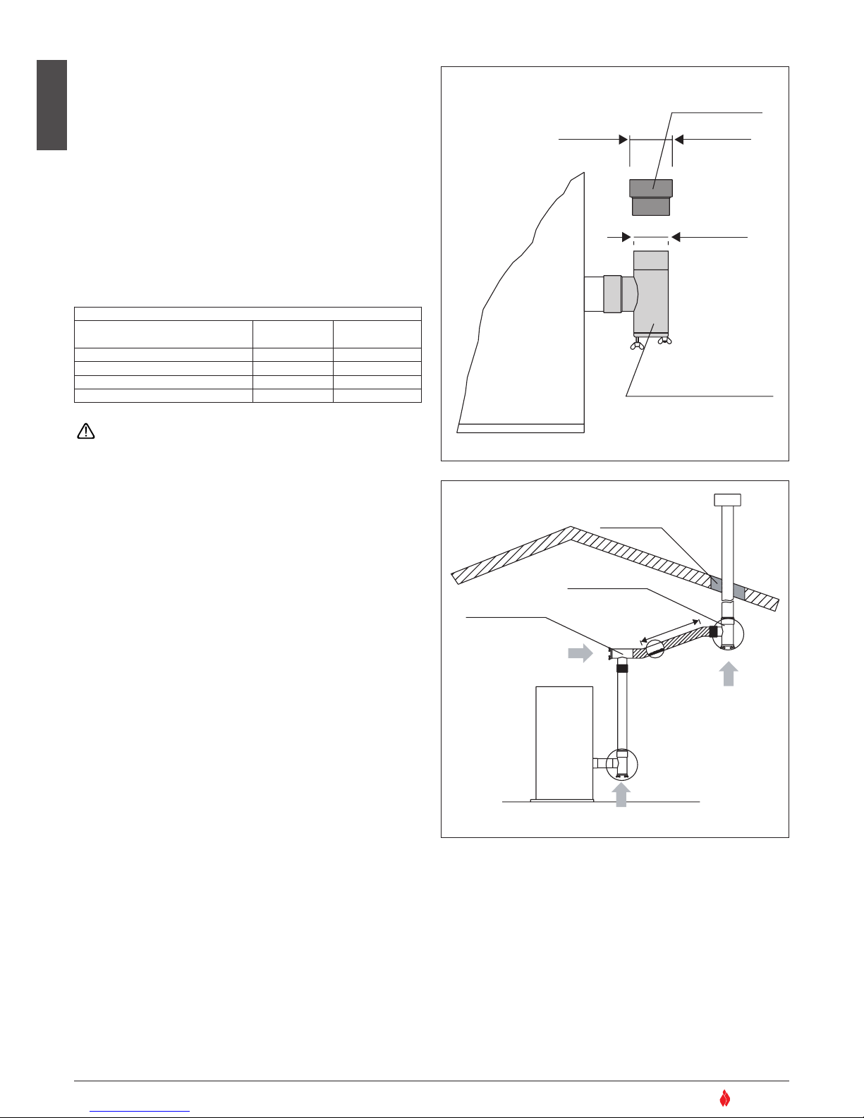
Pipes and maximum usable lengths
Pipes of painted aluminium-clad steel (minimum thickness
1.5mm), stainless steel (AISI 316) or enamelled steel (minimum
thickness 0.5mm) with a nominal diameter of 80 or 100 mm (for
pipes which run inside the flue maximum diameter 150 mm) can be
used.
The male-female connectors must have a minimum length of 50
mm.
The diameter of the pipes depends on the type of installation. The
stove was designed to take 80 mm diameter pipes but, as shown
in Table 1, in some cases the use of double-lined 100 mm diameter
pipes is recommended.
Losses in pressure associated with a 90° bend can be
compared to those incurred by one metre of pipe. An
inspectable union-tee can be considered equivalent to a 90°
bend.
EXAMPLE: : if installing a section greater than 4.5m in length with
80mm diameter pipe, calculate the maximum usable length in the
following ways:
- If a maximum of three 90° bends are used, the maximum length of
the section will be 4.5m
- If a maximum of two 90° bends are used and bearing in mind that a
90° bend can be replaced by one metre of pipe, the maximum length
of the section will be 4.5m+1m=5.5m
- If a maximum of one 90° bend is used and bearing in mind that a 90°
bend can be replaced by one metre of pipe, the maximum length of
the section will be 4.5m+1m+1m=6.5m
Where 100mm diameter pipe must be used, connect it to the stove
flue outlet with a 80mm union-tee then use a 80mm 100mm adaptor
(not supplied by Superior) (Fig. 19).
Union-tee
The use of this type of fitting must allow for the collection of
condensate mixed with soot, which builds up inside the pipe. It must
also permit periodic cleaning of the flue without the need to
disassemble the pipes.
This type of fitting can be bought at Superior retail outlets together
with the pipes.
An example is given below of a flueway connection, which allows
complete cleaning without having to disassemble the pipes (Fig 20).
English
10
SUPERIOR
®
TABLE 1 – LENGHT PIPES
TYPE OF INSTALLATION
WITH 80mm Ø PIPE
WITH DOUBLE-WALLED
100mm Ø PIPE
Maximum length (with three 90° bends) 4.5 m 8 m
For installations more than 1200m above sea level
- Required
Maximum number of bends 3 4
Length of horizontal sections with minimum 3% gradient
2 m 2 m
RACCORDO A T CON TAPPO
A CHIUSURA ERMETICA
RACCORDO
ø 80 > ø 100
ø 80mm
ø 100mm
DT2030337-00
Fig. 19
ISOLANTE
RACCORDO A T
RACCORDO A T
DIREZIONE
DI PULIZIA
DIREZIONE DI PULIZIA
Max 2m
(min. 3%)
DIREZIONE DI PULIZIA
DT2030338-00
Fig. 20
Straight reducer
ø 80 > ø 100
Tee with sealing plug
Insulating material
Tee
Tee
Direction of
cleaning
Direction of cleaning
Direction of cleaning
H07022850 / DT2000426 - 00
Page 11
English
11
SUPERIOR
®
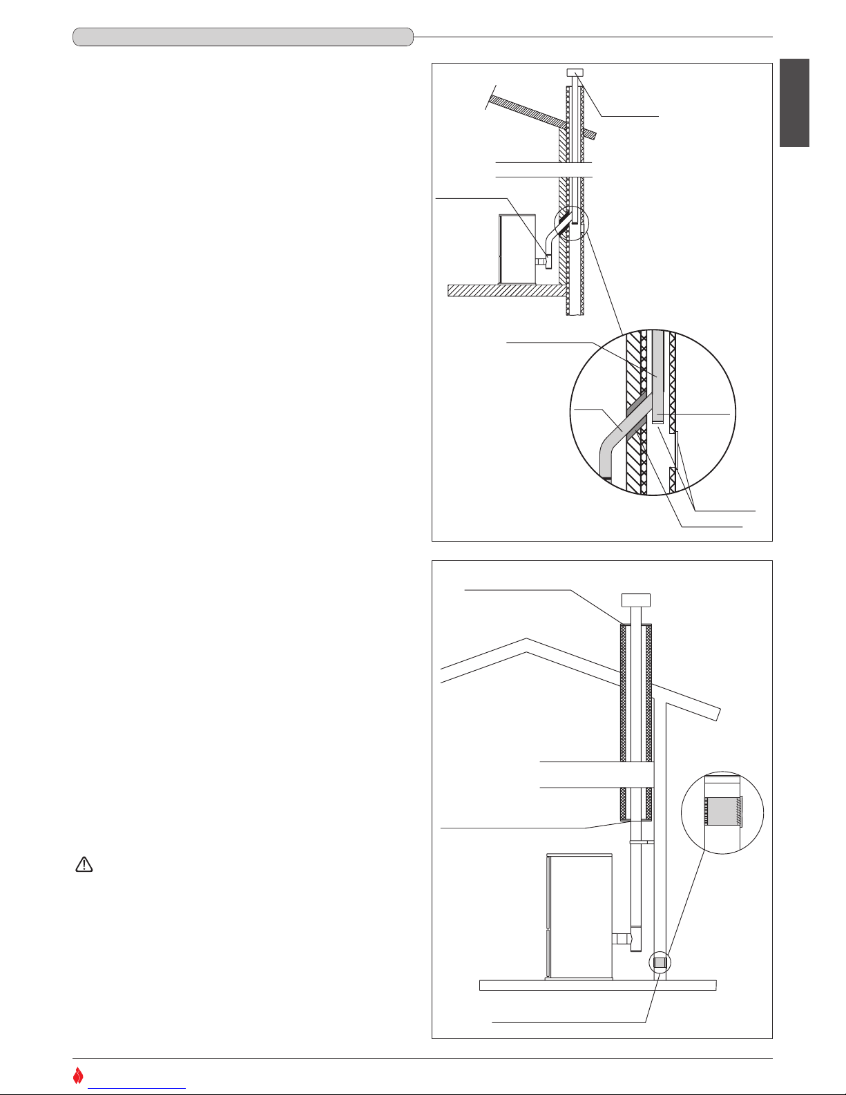
If you wish to use an existing chimney it is strongly recommended that
you have it checked by a professional chimneysweep to ensure that it
is completely airtight. The reason for this is that the smoke, because it
is slightly pressurised, can infiltrate any cracks in the flue and escape
into living spaces. If upon inspection you find that the chimney is not
completely sound, it is recommended that you insert piping made of
new material. If the existing chimney is wide enough we recommend a
pipe with a maximum diameter of 150mm. It is also recommended that
you insulate the chimney flue (Fig. 21-22).
Pipes and bends made by Gruppo Piazzetta S.p.A. are recommended
for connection to the flueway, since they are sized to fit the flue outlet
of the appliance.
Other pipes may be applied after adaptation and checking of the
compatibility of the coupling, taking into account that the pipes and
bends must be made in compliance with current regulations. In this
case, however, Gruppo Piazzetta S.p.A. only guarantees trouble-free
operation for parts that it manufactures and that are used according to
specifications.
Connection to the flue must respect the 40cm minimum safety
distance from heat-sensitive structural components or inflammable
materials (wood panelling, beams or ceilings, etc). (See figures 17-18).
- If the connector has to pass through partitions or walls of inflammable
or heat-sensitive materials, or through load-bearing walls, create:
an insulating barrier equal to or greater than 10cm around the
connector using mineral-based insulating material (rock wool,
ceramic fibre) with a nominal density greater than 80kg/m3.
- If the connector has to pass through non-flammable partitions or
walls, create:
an insulating barrier equal to or greater than 5cm around the
connector using mineral-based insulating material (rock wool,
ceramic fibre) with a nominal density greater than 80kg/m3.
- Check that the connection to the flueway is gas/smoke-tight, since
the appliance operates in a vacuum.
- Check that the pipe does not penetrate too far into the flueway,
thereby choking the pipe for the passage of smoke and combustion
gases.
Ensure that all installation work is carried out to professional
standards.
COMIGNOLO
RACCORDO A T
CON CANNA FUMARIA
NON INTEGRA
INSERIMENTO DI
UN TUBO
SPORTELLI PER
ISPEZIONE
ISOLANTE
Max ø150 mm
ø 80 mm
DT2030339-01
Fig. 21
FLANGIA DI CHIUSURA
FLANGIA DI CHIUSURA ERMETICA
IN ACCIAIO INOX O ALLUMINATO
PRESA D'ARIA ESTERNA
CON GRIGLIA NON RICHIUDIBILE
DT2030340-00
Fig. 22
Insulating material
Tee
Chimney stack
Pipe insertion
With damaged flue
Inspection
windows
Closing flange
Sealing flange in stainless
steel or aluminium
Fresh air intake with
non-closable grille
1.10 CONNECTING TO A CONVENTIONAL CHIMNEY - Fig.21 - 22
DT2010230-02
H07022850 / DT2000426 - 00
Page 12
English
12
SUPERIOR
®
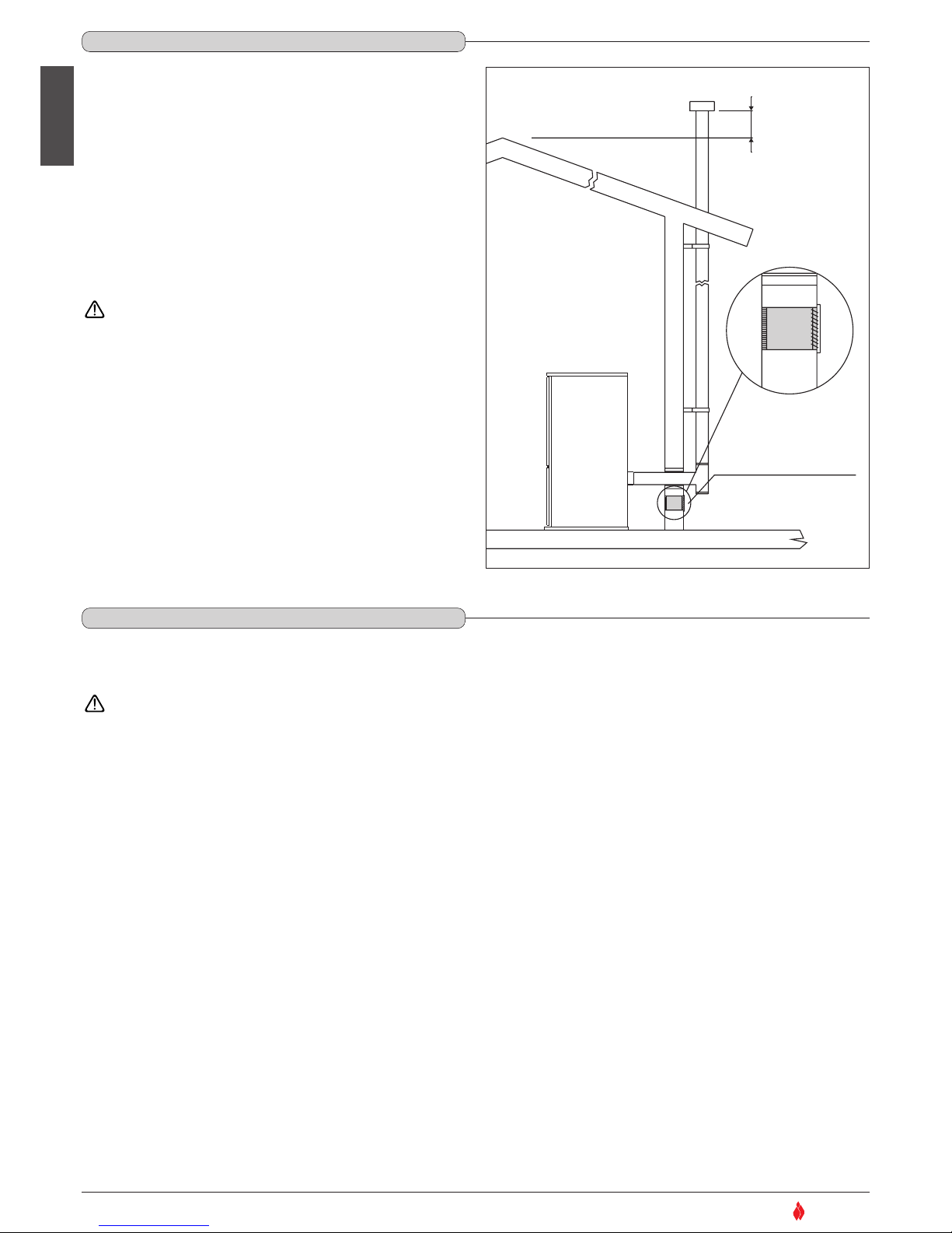
PRESA D'ARIA ESTERNA CON
GRIGLIA NON RICHIUDIBILE
d
DT2030341-00
Fig. 23
An external flue can be used provided it complies with the following
requirements:
- use only insulated stainless steel pipes (double-lined) fixed to the
outside wall of the building (Fig. 23);
- there must be an inspection opening at the base of the flue to permit
periodic checks and maintenance;
- the flue must be fitted at the top with a chimney stack with downdraught cowl, also ensuring compliance with the safety distance from
the roof ridge as outlined in the section entitled “GENERAL RULES”,
under “CHIMNEY STACK”.
Ensure that all installation work is carried out to professional
standards.
Fresh air intake with
non-closable grille
1.11 USING AN EXTERNAL FLUE - Fig. 23
DT2010232-02
1.12 PREVENTION OF DOMESTIC FIRES
DT2010027-02
The product must be installed and used in compliance with the manufacturer’s instructions and European and national standards as well as local
regulations.
When a flue pipe passes through a wall or a ceiling, special installation methods must be applied (protection, thermal insulation,
distances from heat-sensitive materials, etc.) See the paragraph “FLUEWAY”
- It is also recommended that all elements made of combustible or inflammable material, such as beams, wooden furniture, curtaining, flammable
liquids, etc. be kept outside the heat radiation range of the stove and in any case at a distance of at least 80 cm from the heating block.
- For other information, see the paragraph “MINIMUM SAFETY DISTANCES” and “CONNECTION TO A CONVENTIONAL CHIMNEY”.
- The flue pipe, chimney stack, chimney and fresh air intake must always be free of obstructions, clean and checked periodically, that is, at least
twice during the seasonal period from the lighting of the stove and during its use. When the stove has not been used for some time it is advisable
to carry out the checks mentioned above. For further information, consult a chimneysweep.
- Only use recommended fuels (See section “FUEL”).
H07022850 / DT2000426 - 00
Page 13
Cladding: in enamelled steel and hand-made majolica
Interior: steel fireplace
Baffle plate and hearth: in cast iron
Grate: in cast iron
Door: in cast iron with ceramic glass heat resistant up to 750°C
Handle: in enamelled steel
Control panel: display with digital controls and remote control
Timer thermostat: standard with daily and weekly programming modes divided into two time bands
Power setting: from 1 to 5
Ash drawer: removable
Fuel: natural pure wood pellets (see section “FUEL”)
Heating: forced ventilation
Data obtained under laboratory conditions with pellets calorific value of 5kwh/kg
N.B.: The above data may vary according to the characteristics of the pellets being used. (See section “FUEL”)
Technical data for flue calculations
English
13
SUPERIOR
®
2.0 TECHNICAL CHARACTERISTICS AND SPECIFICATIONS
DT2010188-02
2.1 FEATURES
DT2011529-00
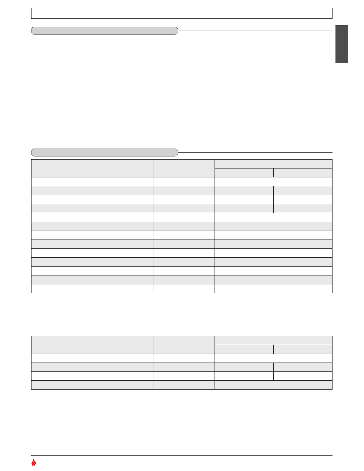
2.2 TECHNICAL DATA
DT2010186-04
Unit
SOFIA
(at rated power) (at minimum power)
Rated / minimum thermal power kW 10.5 / 4.0
Hourly fuel consumption kg/h 2.6 1.0
Efficiency % 84.5 80.5
CO content (with 13% O2)
% 0.022 0.009
Maximum power rating W 350
Power rating (max/min) W 150 / 90
Electrical power supply V 230
Frequency Hz 50
Fuel tank capacity kg / (l) 35 / (54)
Exhaust outlet diameter cm ø8
Fresh air intake with minimum useful section cm² 100
Weight with cladding kg 184
Packing sizes (DxWxH) cm 88x68x140
Unit
SOFIA
(at rated power) (at minimum power)
Rated / minimum thermal power kW 10.5 / 4.0
Mass of smoke g/s 10.26 8.93
Average temp. smoke in gas outlet pipe °C 206.0 134.1
Minimum draught Pa 12
H07022850 / DT2000426 - 00
Page 14
English
14
SUPERIOR
®
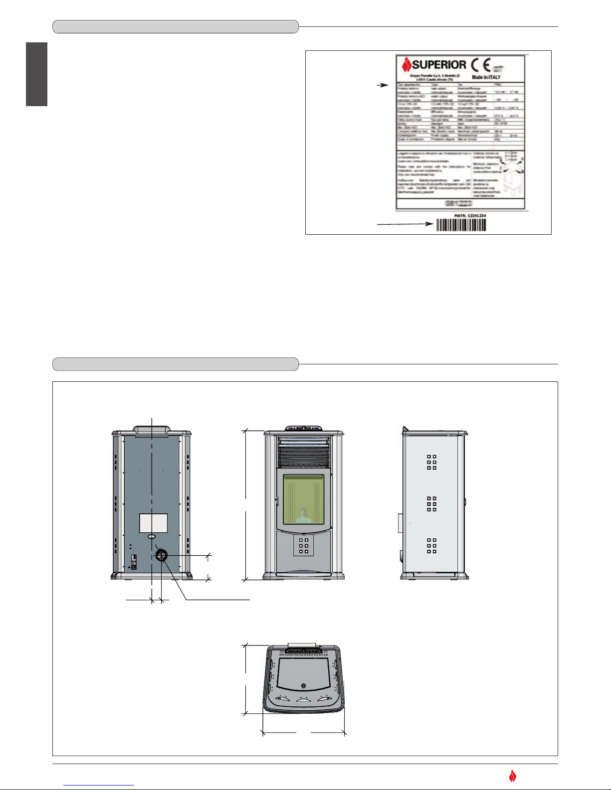
118
65
54
7,7
19,7
Diametro 8 cm
Dimensions in cm
The rating plate gives the data and ratings of the appliance.
If the rating plate is missing, has been removed or tampered with,
any installation and maintenance operations are made difficult due
to lack of product identification.
In the event of damage, please ask the Superior after-sales service
centre for a copy.
Product name
Serial number
DT2031365-01
Diameter Ø8
2.3 PRODUCT IDENTIFICATION DATA
DT2010041-05
2.4 DIMENSIONAL DIAGRAM
DT2030373-01
H07022850 / DT2000426 - 00
Page 15
English
15
SUPERIOR
®
A
C
D
E
I
G
F
H
L
M
N
O
P
Q
R
S
V
AL1
N
AL2
ACC.
COC.
FUMI
SCAM.
F
N
SERIALE
DISPLAY
TERM.
-TC1+
N.AMB.
N.H2O
N.PEL.
BLU
GND
+5V
ENC
4 2
1
11
3
5
2
4
3
5
2 4 5
1
4 5
6
6 6
3
7
3
6
1
5
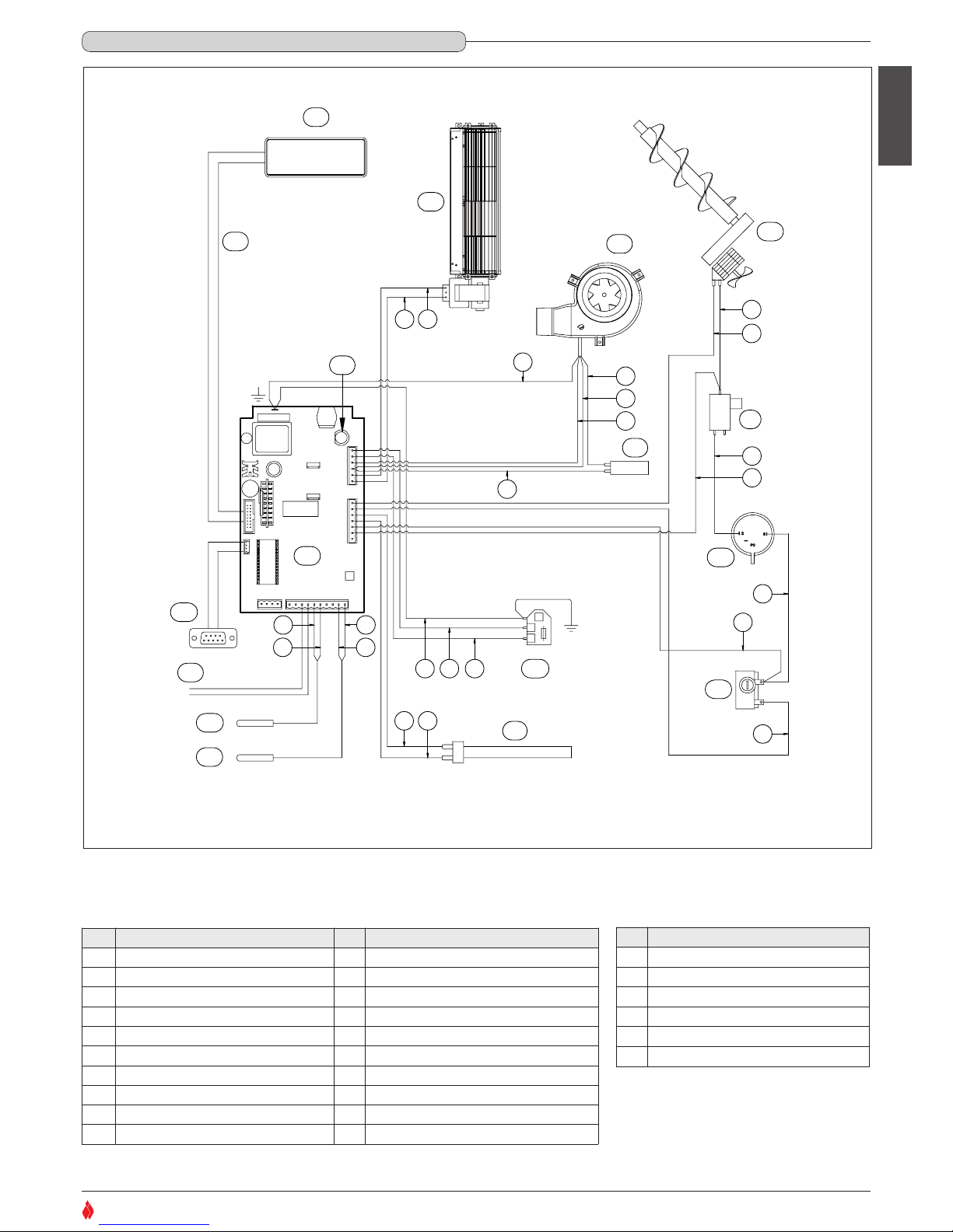
Pos. Key to parts Pos. Key to parts
A Display of control M Power supply with fuse (5X20 4AH250V)
B - N Smoke sensor
C Room fan O Room sensor
D Pellet-loading auger P External thermostat connection
E Flue gas fan Q Serial port DB9
F Capacitor R Motherboard
G N.O. Pressure switch (normally open) S Fuse 5X20 4AL250V
H N.C. 80° thermostat (normally closed) T I Microswitch U L Ignition glow plug V Flat cable
N° Key to colours
1 White
2 Yellow-green
3 Black
4 Brown
5 Blue
6 Red
2.5 WIRING DIAGRAM
DT2031594-00
H07022850 / DT2000426 - 00
Page 16
English
16
SUPERIOR
®
To prevent accidents or damage to the product we recommend the
following:
• unpacking and installation must be carried out by at least two people;
• every operation involving movement of the product must be carried
out with the proper tools in full compliance with current safety
regulations;
• the packaged product must be kept in the position according to the
directions shown by the diagrams and notices on the pack;
• if ropes, straps or chains are used, ensure that they are able to take
the weight of the pack and that they are in good condition;
• use slow continuous movements when moving the pack to avoid
jerking the ropes, chains, etc.;
• do not tilt the package excessively to avoid toppling;
• never stand in the vicinity of loading/unloading equipment (forklift
trucks, cranes etc).
Unpack the product being careful not to damage or scratch it,
take the accessories pack and any pieces of polystyrene or
cardboard used to wedge moveable parts etc. out of the stove
firebox.
Keep packaging (plastic bags, polystyrene, etc.) out of reach
of children, since it could be a potential source of danger, and
dispose of according to local regulations.
The wood pellet is obtained by pressing wood sawdust left over from the
working of natural dried wood. The typical small, cylindrical form is obtained
by passing the material through a die. Thanks to lignin, a natural element
which is released during the pressing of the raw material, the pellets acquire
a good consistency and compactness without requiring treatment with
additives or caking agents.
There are various types of pellet on the market with qualities and
characteristics that vary depending on the processes they have undergone
and the type of wood used in their production.
Since the characteristics and quality of the pellet considerably affect
stove performance, efficiency and proper operation, we recommend that
you use high-quality pellets.
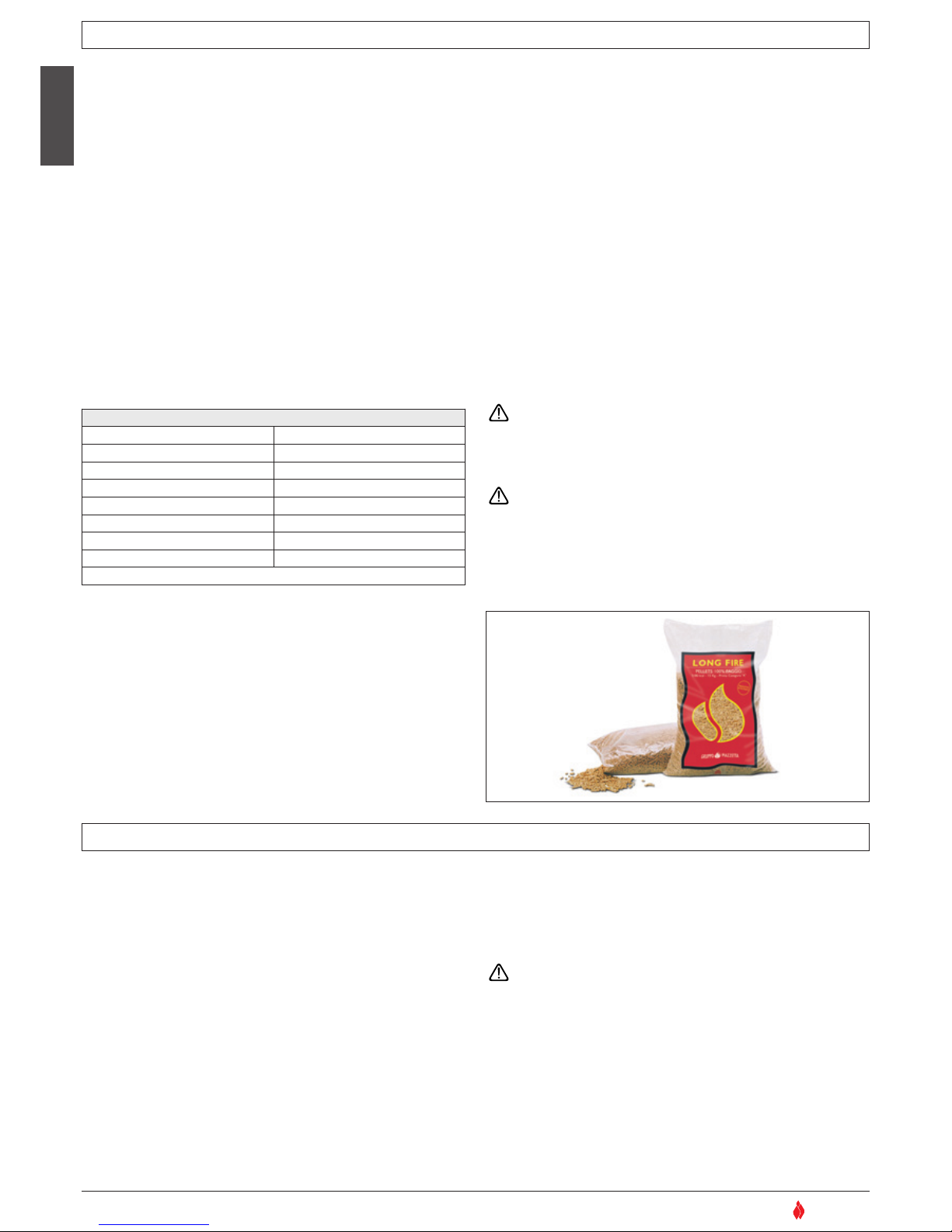
Gruppo Piazzetta S.p.A has tested and programmed its stoves and can
ensure best performance and trouble-free operation using pellets with
the following specific characteristics:
To ensure trouble-free operation:
DO NOT use pellets with dimensions other than those recommended by the
manufacturer
DO NOT use poor quality pellets containing sawdust, bark, maize, resins or
chemical substances, additives or adhesives.
DO NOT use damp pellets.
Choosing other and unsuitable pellets:
- obstructs the grate and flue gas pipes
- increases fuel consumption
- reduces efficiency
- means that proper stove operation cannot be guaranteed
- causes dirt to build up on the glass
- leaves particles which have failed to burn and heavy cinders
The presence of moisture in the pellets increases their volume and
causes them to split which in turn causes:
- malfunction of the fuel-loading system
- inefficient combustion
Pellets should be stored in a sheltered, dry place.
To use good quality pellets with dimensions and heat-producing properties
other than those recommended above, it will be necessary to change the
stove operating parameters.
This “customisation” of stove settings must be carried out at a
Gruppo Piazzetta S.p.A. Service Centre or by specially qualified
personnel authorised by Gruppo Piazzetta S.p.A.
Using pellets that are out of date or not in conformity with the
manufacturer’s recommendations not only damages the stove and
jeopardises its performance, but can render the guarantee null and
void and relieves the manufacturer of all liability.
.
DT2030346-00
Fig. 24
Pellet characteristics
Components natural pure wood pellet
Length, approx. 10 – 30 mm
Diameter, approx. 6 – 6.5 mm
Apparent density, approx.
650 kg/m
3
Specific weight, approx.
> 1.0 kg/dm
3
Net heat value, approx. 5 kWh/kg
Moisture content, approx. < 8%
Residual ash, approx. <0.5%
N.B. the above data refer to beech/fir wood pellets
3.0 FUEL
DT2010233-04
4.0 PREPARING FOR INSTALLATION
DT2010074-06
H07022850 / DT2000426 - 00
Page 17
English
17
SUPERIOR
®
Pursuant to current regulations on the safety of electrical equipment, you must contact a Superior After-Sales Service Centre or a qualified
electrician for all and any work connected with installation, maintenance or servicing that involves access to electrical parts.
External pressure switch
• The stove is fitted with an external pipe tap for measuring the pressure (vacuum) in the flue gas outlet pipe. Authorised personnel should carry
out this verification and control whilst the stove is being installed.
Cladding
• Having completed assembly of the stove and installed any external room thermostat, proceed with assembly of the stove cladding, referring to
the ceramic cladding instruction booklet provided with the stove.
5.0 INSTALLATION
DT2010189-00
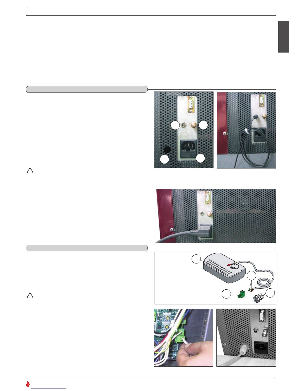
• The stove comes with a power cable which must be connected to
a 230v/50Hz supply. Connection to the rear of the stove is shown
in fig. 27.
• The power rating is indicated in the paragraph “TECHNICAL
DATA” in this booklet.
• According to law the installation must be earthed and include a
residual current circuit breaker.
• Ensure that in its normal position the power cable does not come
into contact with any heated parts.
Ensure that the electrical socket is accessible also after
installation of the stove.
• When installing the stove, it is necessary to connect the room
sensor (provided) in the correct socket (fig. 26). The sensor can
be positioned as shown in fig. 26, otherwise remove the band and
uncoil the lead and then place the sensor in a spot where a more
accurate room temperature reading can be obtained.
The appliance is designed for connection to an external room
thermostat. To connect the thermostat use a 2x0.5mm
2
cable
secured with a PG7 cable gland to be inserted in the relative hole
in the rear panel(fig. 30). Only authorised personnel should carry
out this operation.
Installation can be carried out with any type of room
thermostat but requires a PG7 cable gland similar to that
shown in fig. 28. To connect the room thermostat to the
electronic board, refer to the wiring diagram.
Proceed as follows for installation:
• disconnect from the main power supply before opening the
appliance.
• Insert the thermostat cable through the PG7 gland and then
insert the gland in the hole in the rear panel (fig. 30).
• Connect the room thermostat cable terminal to the 2-pin terminal
of the electronic board (fig. 29).
5.1 ELECTRICAL CONNECTION AND THE ROOM SENSOR CONNECTION - Fig.25 ÷ 27
DT2010195-00
DT2030076-00
Fig. 28
1
2
3
4
5.2 INSTALLING THE EXTERNAL THERMOSTAT – Fig. 28 ÷ 30
DT2010190-00
DT2010071-04
1 Thermostat.
2 Electronic board 2-pin terminal.
3 Cable clamp.
4 Thermostat cable terminal.
DT2030285-00
DT2030284-00
Fig. 25 Fig. 26
DT2030286-00
Fig. 27
1
2
3
4
1 External socket for connection of room sensor.
2 Socket for power lead.
3 External pressure pipe tap.
4 Hole for inserting cable gland PG7 for connection of external
DT2030077-00
Fig. 29
DT2030228-00
Fig. 30
H07022850 / DT2000426 - 00
Page 18
• Do not use the stove as a cooking appliance.
• Ensure that the room in which the stove is installed is sufficiently well ventilated (fresh air intake).
• Ensure that all joints in the flue are hermetically sealed using a silicone- (not cement-) based sealant which is resistant to temperatures of up
to 250ºC and which shows no sign of deterioration.
• Check (or have checked) regularly that the flue is clean.
• Under no circumstances use fuels other than pellets.
• Remove any deposits of unused pellets left by failed ignition before restarting the stove.
During operation some parts of the stove (door, handle, controls, ceramic parts) can reach high temperatures. Take great care and
all the necessary precautions, especially in the presence of children, the elderly or disabled and pets.
Keep any inflammable object well away from the stove while it is in use (MINIMUM 80 cm from the front panel).
While in use the door must remain closed and the glass must be present and intact.
The removal of the protective grille inside the pellet hopper is strictly prohibited.
If replenishing with pellets while the stove is lit, ensure that the bag does not come into contact with any hot surfaces
English
18
SUPERIOR
®
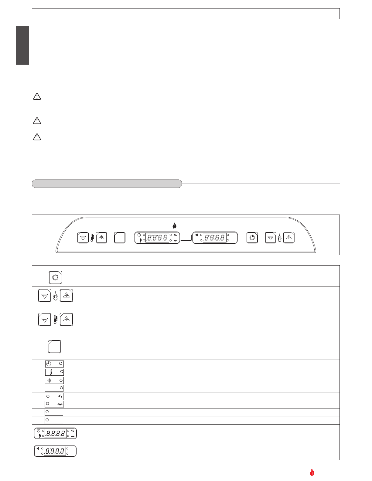
• The stove is equipped with a digital control panel which allows the user to control the various functions.
The control panel keys and their various functions are listed below. These have been numbered in order to make identification easier.
DT2010035-06
6.0 USE
DT2010191-02
6.1 CONTROL PANEL - Fig. 31
DT2010196-00
4
65
3
SET
21
ON-OFF key
• Manual startup and shutdown.
• Exit from programming mode.
65
3
SET
21
Power keys
• Controls heat distribution with settings 1 (minimum power) to 5
(maximum power). This in turn affects refuelling times.
21
Temperature and timer control
keys
Allows:
• setting the desired room temperature from 7 to 30°C.
• programming the timer.
Key 1 allows the user to display the current time and temperature.
3
SET
21
Function select
Allows:
• access to the various programming modes: clock, timer and technical settings.
• setting the desired room temperature.
3
SET
1
2
5
6
4
Timer functions The LED lights up if the timer is activated.
OK
3
SET
1
2
5
6
4
Temperature The LED lights up when the desired temperature is reached.
OK
3
SET
1
2
5
6
4
Remote control reception The LED lights up when data from the remote control is received.
SET
OK
3
SET
1
2
5
6
4
Programming The LED lights up when programming is in progress.
SET
OK
3
SET
1
2
5
6
4
Fuel loading The LED lights up when the automatic fuel-loading spiral chute is in use.
SET
OK
3
SET
1
2
5
6
4
Pilot light The LED lights up when the pilot light is on.
AL. C
SET
OK
3
SET
1
2
5
6
4
Thermostat alarm The LED lights up when the thermostat alarm is activated.
AL. F
AL. C
SET
OK
3
SET
1
2
5
6
4
Pressure reader alarm The LED lights up when the pressure reader alarm is activated.
4
65
3
SET
AL. C
AL. F
SET
OK
21
Display
Shows:
• Current time/temperature
• Power levels
• Programming codes
• Alarm indicators.
DT20140001-00
H07022850 / DT2000426 - 00
654
321
AL. C
AL. F
SET
OK
SET
SUPERIOR
®
DT2030287-00
Fig. 31
Page 19
English
19
SUPERIOR
®
19
6.2 LIGHTING FOR THE FIRST TIME
DT2010082-05
• Before lighting the stove for the first time, check that the grate is properly placed and pushed back towards the baffle plate.
• There will be odours when lighting the first few times due to the evaporation of paints and oils used during the manufacturing process.
During this stage, air the room well where the stove is installed and avoid staying there any length of time since the fumes being given off could be harmful to persons or pets.
The stove body should have settled down and the paints fully evaporated after having lit the stove a few times.
To this end, follow the instructions given below when using the stove.
• Operate at medium power for the first 5-6 hours after igniting the fuel (the expansion caused by the heat during this stage will allow the stove body to settle).
• After the settling-down stage the stove must be set to operate at maximum power for a period between 6 and 10 hours, depending on the amount of paint on the stove
body that must be evaporated off.
The time indicated for operation at maximum power does not necessarily have to be continuous, but may be divided up into two periods separated by an interval of at least
3-4 hours with the stove shut down.
At the end of the recommended period the paint will have evaporated and the stove should be used at the suitable power for normal use.
If necessary the stove may be used for a further period at maximum power to ensure complete and final disappearance of all paint residue.
When the hopper is being loaded for the first time the loading auger needs time to fill up; during this stage the pellets are not distributed inside the firebox and it is highly
probable that the first attempt at ignition fails. If the alarm is activated, shut down the stove by pressing the ON/OFF key for a few moments, remove the fuel in the grate and
then set the stove for a new ignition process.
Before proceeding with the ignition remember:
ensure that the furnace door is well closed;
• that the fuel tank is full or at least contains enough fuel to run for the desired period.
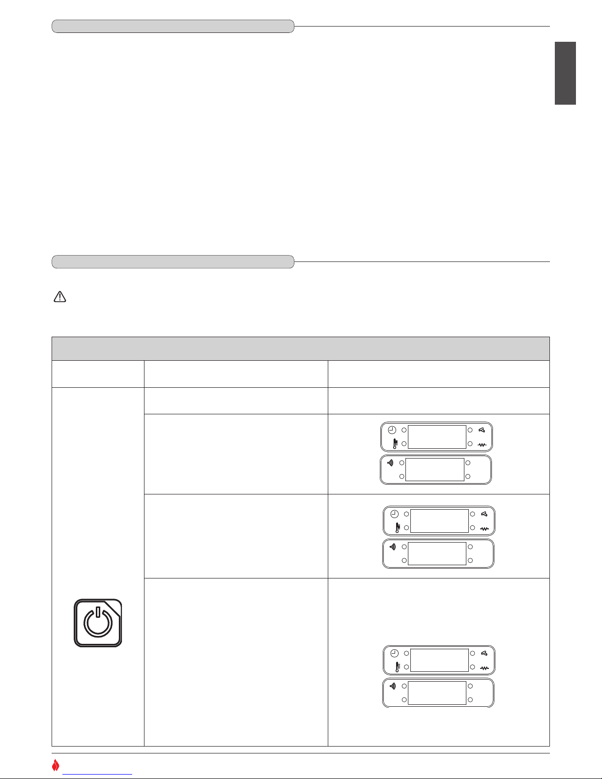
When the stove is connected to the power supply, but is not yet lit, the display will show the current time on the left (example 12:30) and the word OFF on the right.
6.3 STARTUP AND NORMAL OPERATION
DT2010192-00
STARTUP
Action Description Display
4
Starts a cycle of three phases which take the
stove into normal operation:
On the right part will appear three circles in succession
indicating the current phase of ignition.
• Phase one: CHECK UP (first 10 seconds)
- The pilot light ignites (the LED on the
display lights up).
AL. C
AL. F
SET
OK
• Phase two: IGNITION
- The extractor fan starts up.
- The fuel-loading chute is activated and starts to
feed pellets into the burner (the LED on the
display lights up at fixed time intervals).
AL. C
AL. F
SET
OK
• Phase three: STARTUP
- If the pilot light has triggered the combustion process,
the fuel-loading chute will increase the supply to allow
a period of stabilisation and therefore a complete
combustion of the pellets in the subsequent operation.
- If during the startup phase the sensor on the exhaust
outlet shows an increase in temperature (sign that the
combustion process is underway), the stove is
considered to be lit and operating normally.
- If during the startup phase the sensor at the exhaust
outlet does NOT show an increase in temperature (sign
that the combustion process is not underway), the
stove should be considered off; a new ignition cycle will
begin automatically and the three preceding phases will
be repeated in succession.
AL. C
AL. F
SET
OK
Hold the on/off key
down for several
seconds:
DT2040032-01
AA
uu uu ii oo
o
SCROLLING READOUT
PHASE ONE
AA
uu uu ii oo
oo
SCROLLING READOUT
PHASE TWO
•
LED LIGHTS
AA
uu uu ii oo
ooo
SCROLLING READOUT
PHASE THREE
•
LED LIGHTS
H07022850 / DT2000426 - 00
Page 20
English
20
SUPERIOR
®
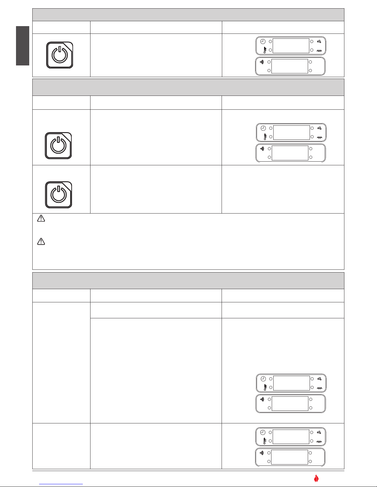
FAILED IGNITION
Action Description Display
4
A second failed ignition will be indicated by an alarm
(a single tone every five seconds) and on the display.
This process is activated if the fuel doesn’t light, if the
tank is empty, or if the temperature fails to rise as
expected.
AL. C
AL. F
SET
OK
DT2040043-00
N o
A C C
FAILED IGNITION: WHAT TO DO
Action Description Display
4
• The alarm should stop
• Verify the cause of the failed ignition.
Always remove any fuel in the burner before
starting a new ignition process.
AL. C
AL. F
SET
OK
4
• The startup up process will be activated as detailed
above.
If the appliance does not ignite properly the main cause could be either insufficient maintenance (consequently refer to the “Maintenance”
section) or the poor quality of the pellets (refer to the “Fuel” section). It is therefore recommended to check as above before attempting to relight
the appliance.
If the stove occasionally fails to ignite it could be caused by:
- pellet composition or size not in compliance with the specifications given in this booklet (see the “FUEL” section);
- insufficient mains voltage, whether in the form of intermittent voltage drops or a constantly lower value.
In the above cases any call-out of the service centre is not covered by the warranty, since the problem is not due to a defect in the product.
DT2040044-03
Shut the stove down by
holding the on/off key
down for several seconds.
Restart the stove
using the same key.
OO:OO
O
f f
NORMAL OPERATION
Action Description Display
Once ignited successfully, the stove will function
normally.
• In the right part of the display the word ‘on’ will
appear followed by the chosen power setting (1-5).
The left part will show the room temperature or the
current time
(SEE ‘ACTIVATION/DEACTIVATION OF THE
TEMPERATURE/TIME DISPLAY’ BELOW).
During normal operation the user can regulate:
• power level, choosing one of FIVE settings (keys 5
and 6)
•
The desired room temperature from 7°C to 30 °C (press
SET then keys 1 and 2).
If during normal operation the power level is lowered
from 5 to 1, the fan (after a pause of 15 seconds) will
run at maximum power for around four minutes,
allowing the stove to cool down.
AL. C
AL. F
SET
OK
During normal operation the burner’s automatic
cleaning system will activate periodically, the
frequency varying according to the settings preprogrammed by Superior personnel. This operation
removes ash deposits and other buildups which
impede the correct functioning of the stove.
AL. C
AL. F
SET
OK
DT2040033-00
20oC
O N
4
P
U L
O N
4
H07022850 / DT2000426 - 00
Page 21
English
21
SUPERIOR
®
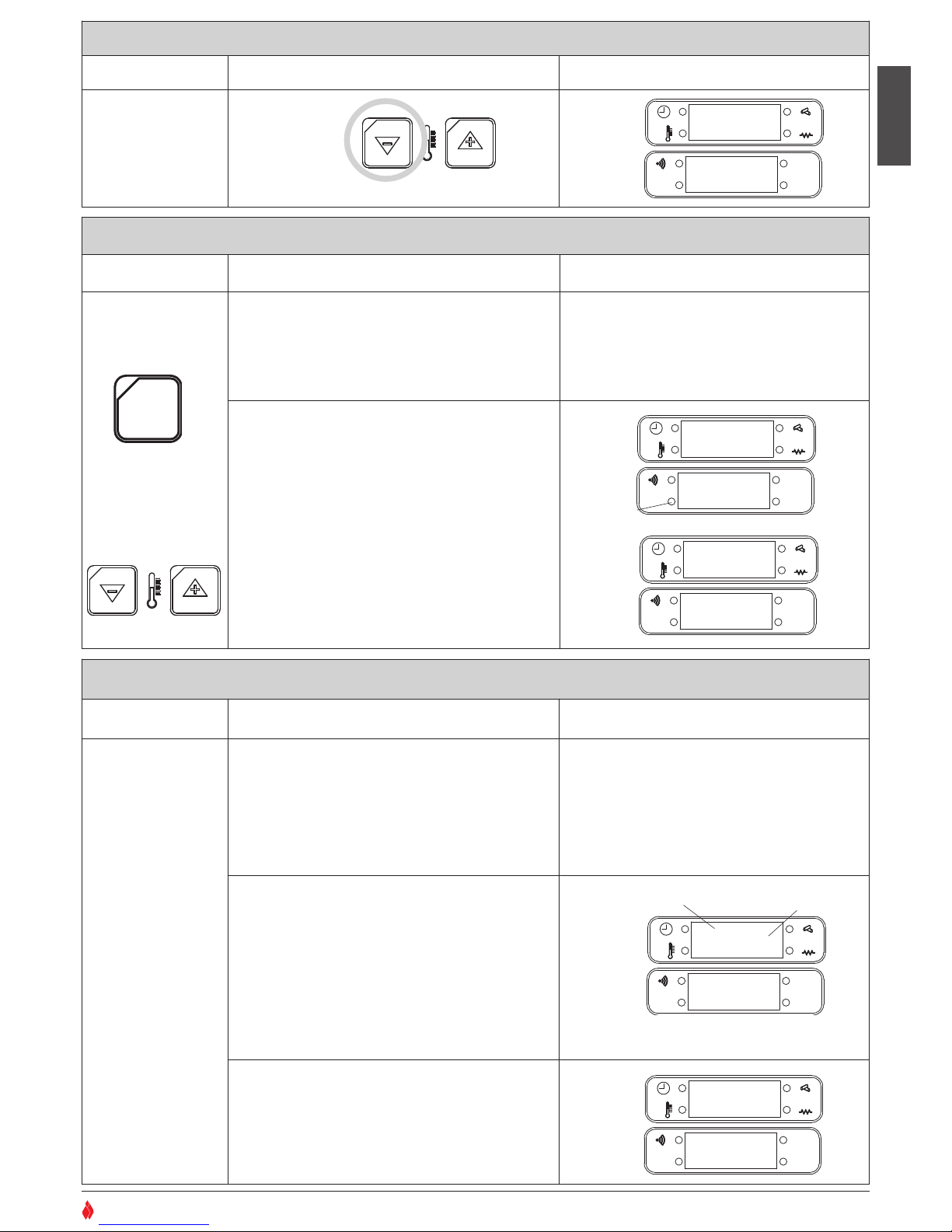
DISPLAY TIME/TEMPERATURE
Action Description Display
At whatever time the
display will show the
room temperature
and the correct time,
whether the stove is
lit or not.
21
AL. C
AL. F
SET
OK
DT2040034-00
Hold down
key 1 for
several seconds.
19:3O
22
o
C
INTERNAL THERMOSTAT (setting desired room temperature)
Action Description Display
To change the
temperature setting
press key 3 SET.
Then press key 2 to
increase the
temperature, key 1
to reduce the
temperature.
The stove is equipped with an internal thermostat
which regulates the power according to the desired
room temperature (7°C - 30°C).
To function properly the sensor provided with the
stove must be positioned correctly.
If during normal operation the room temperature is
lower than that programmed:
The corresponding LED remains off.
• The stove will run at the power level that has been
input. This will be shown on the display.
When the room temperature reaches the programmed
level: the corresponding LED on the display lights up.
• The stove will run at minimum power even if the
programmed power level continues to be shown on
the display.
AL. C
AL. F
SET
OK
DT2040035-00
3
SET
21
AL. C
AL. F
SET
OK
•
LED LIGHTS
LED OFF
20oC
O N
4
20
o
C
O N
4
EXTERNAL THERMOSTAT
Action Description Display
Set the temperature
of the room sensor minimum value
(7ºC)
The running of the stove can be regulated by any kind
of external thermostat connected to the electronic
board (see electrical diagram). The thermostat is
connected using cable type 2x0.5mm2stopped with a
PG7 connector and inserted in the appropriate socket
on the rear panel (fig 30). This operation should be
undertaken by authorised personnel.
To check on the display if the stove is operating using
the external thermostat, you must input a special code
which will allow the temperature to be shown. If not, the
stove will still run with an external thermostat but there
will be no reading on the display. If during normal
operation the temperature is lower than that
programmed:
• the corresponding LED on the display remains off
• the display indicates the chosen power level
• the stove will operate at the power level input.
AL. C
AL. F
SET
OK
When the room temperature reaches the programmed
value:
• the corresponding LED lights up
• the stove runs at minimum power even if the input
power level is shown on the display.
AL. C
AL. F
SET
OK
DT2040045-00
20oCt
O N
4
ROOM TEMPERATURE
LED OFF
20oC
O N
4
LED LIGHTS
•
FLASHING LED
FLASHING T
•
H07022850 / DT2000426 - 00
Page 22
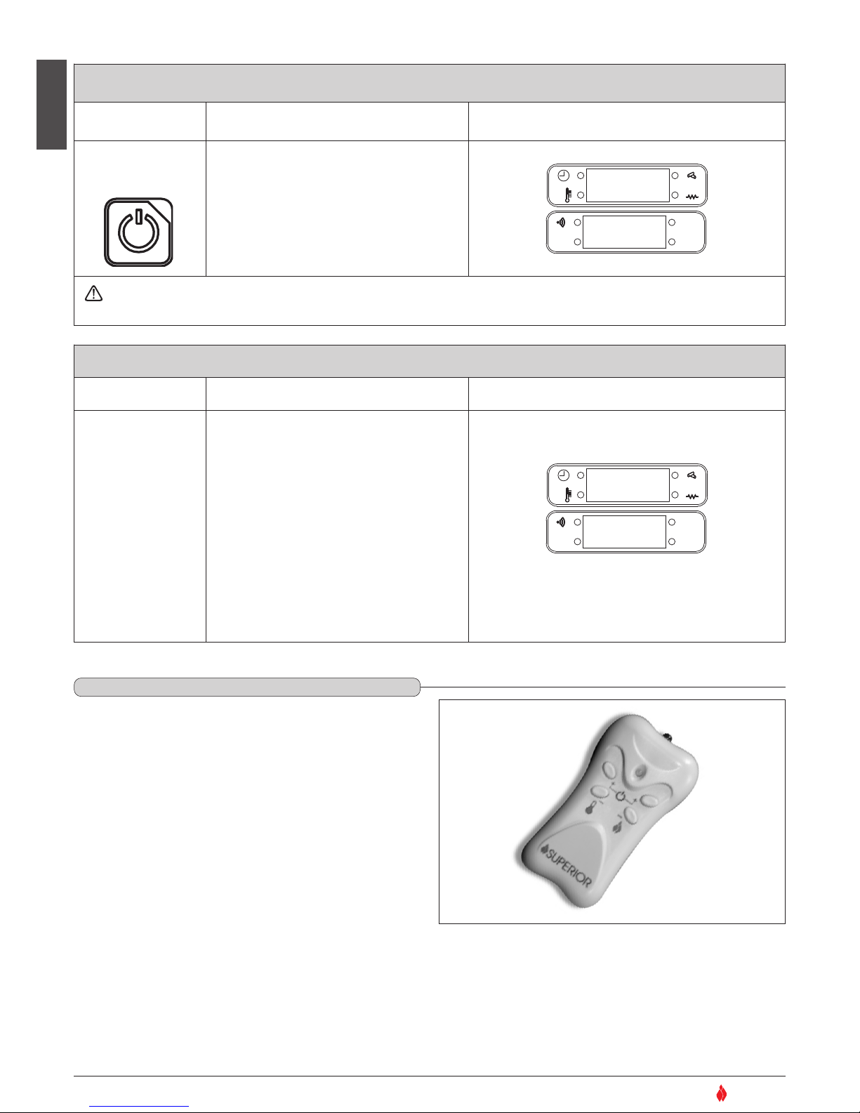
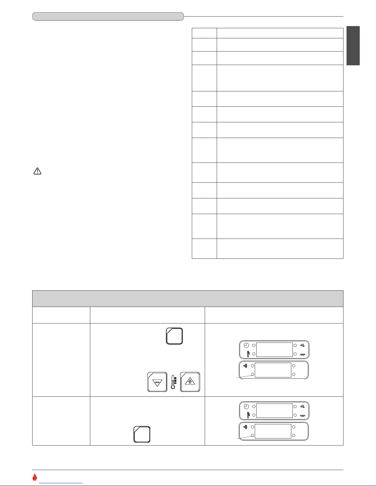
The stove’s control panel has been set to receive some commands
by remote control.
• Startup/Shutdown: by pressing the two ‘+’ keys simultaneously
the stove can be turned on or off.
• Power level: when operating normally, pressing the ‘+’ and ‘-’ keys
above the flame symbol will select one of the stove’s four power
levels.
• Temperature: when operating normally, pressing the ‘+’ and ‘-’
keys above the thermometer symbol will select the desired room
temperature (7-30°C).
English
22
SUPERIOR
®
SHUTDOWN
Action Description Anzeige auf dem Display
4
Fuel loading will stop, while the cooling fan and
the extractor fan will continue to run for
another ten minutes until the stove has cooled
AL. C
AL. F
SET
OK
Do not unplug the stove from the power supply at this stage as this could cause internal problems and compromise future
startup operations.
DT2040046-00
Hold the ON/OFF key
down for several
seconds
12:OO
O
f f
INTERRUPTION OF ELECTRICITY SUPPLY
Action Description Display
In the event of a brief interruption of the
electricity supply the stove will restart
automatically.
• The burner’s automatic cleaning system will
activate.
• The fan will run at full power to allow the stove
to cool.
• The automatic restart cycle will begin
(functions detailed above in ‘STARTUP’ will
activate automatically).
• Once the ignition cycle has been completed the
stove will operate normally at power level 2.
The stove will continue running normally at
power level 2.
AL. C
AL. F
SET
OK
DT2040047-00
P U L
DT2030079-00
Fig. 32
6.4 REMOTE CONTROL - Fig. 32
DT2010084-01
H07022850 / DT2000426 - 00
Page 23
English
23
SUPERIOR
®
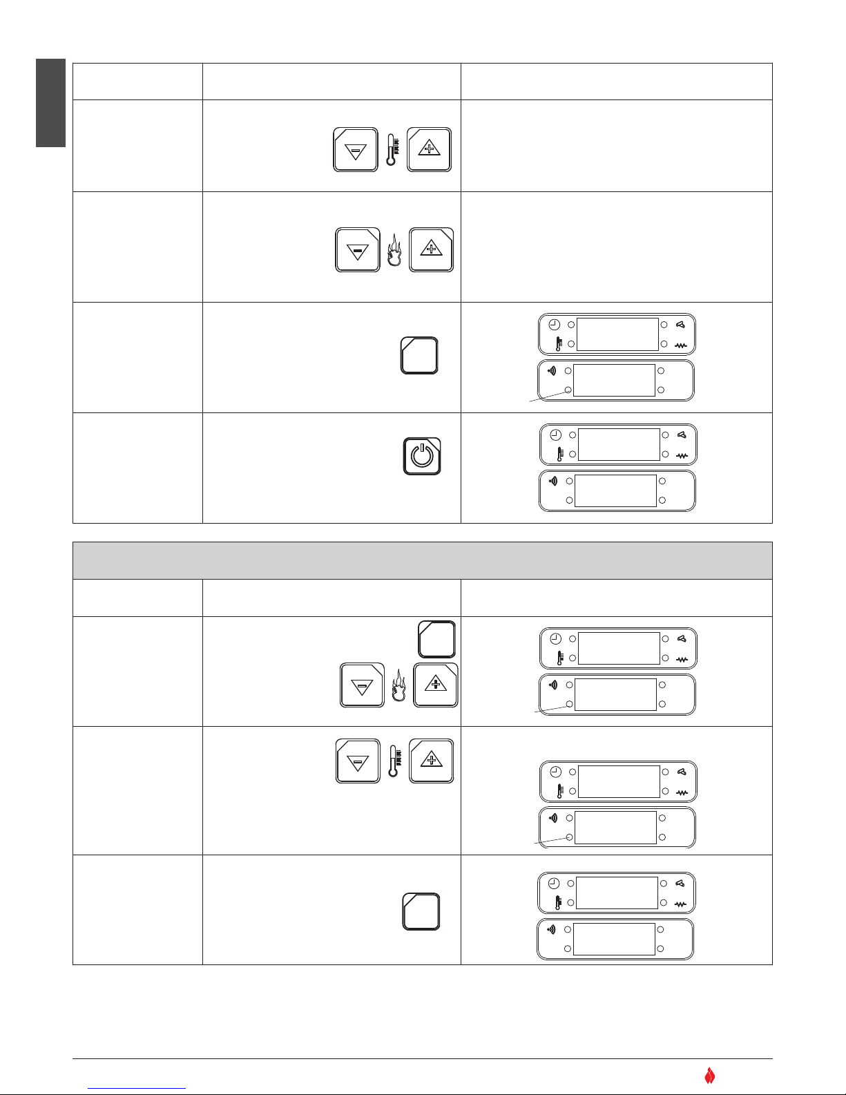
The timer allows the user to programme the stove to start up and
shut down automatically without any manual intervention.
A maximum of two cycles can be programmed:
For example: Cycle one: from 6 until 9 am
Cycle two: from 8.30 until 11 pm
The two cycles can be activated or deactivated on each of the days
of the week (eg, if you want the stove to be lit from 6 until 9 on
Monday, Tuesday but not on Wednesday, and so on…)
Programming codes and relative functions
During programming certain codes will appear in the right part of
the display. These represent the functions described at side:
Setting the timer
Setting the timer for the first time, remember to set the
clock, inputting the current day, hour and minute, as with a
new watch. This will be neccessary only the first time that the
clock is activated. To access the timer set mode, press the
keys in the sequence described below. (NB: at any time exit
the timer set mode and change any data erroneously
confirmed by pressing the ON/OFF key. Re-enter the mode
by repeating the sequence from the beginning and using the
SET key to advance to the point at which you exited.)
Code FUNCTION
01u
Sets the current day of the week.
02u
Sets the current time.
03u
Activates/deactivates the alarm during operation.
Activates/deactivates the display of time and
temperature.
05u
Activates/deactivates timer programming mode.
06u
Inputs startup time for first operating cycle.
07u
Inputs shutdown time for first operating cycle.
08u
Selects the days of the week (shown as: Lu, Ma, Me,… Do) on
which first cycle will be activated ON or deactivated OFF
09u
Selects the desired temperature
Selects the power level: 1 minimum, 4 maximum
10u
Inputs the ignition time in the second operating cycle
11u
Inputs shutdown time in the second operating cycle
12u
Selects the days of the week (shown as: Lu, Ma, Me,… Do) on
which first cycle will be activated ON or deactivated OFF
13u
Selects the desired temperature
Selects the power level: 1 minimum, 4 maximum
6.5 TIMER
DT2010193-00
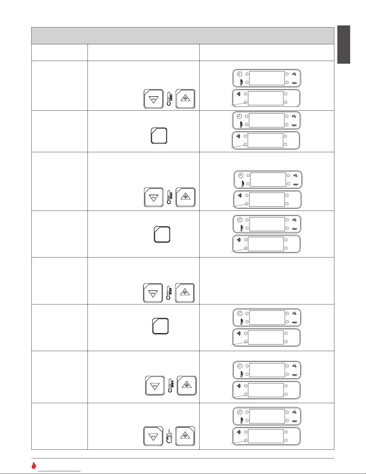
SETTING THE CLOCK (current day/time)
Function Action Display
Set the day
Press the SET key then key 6.
Press key 2 to advance through the
days of the week.
Press key 1 to return through the
sequence.
AL. C
AL. F
SET
OK
Confirm setting and
move to next section.
Press the SET key to confirm.
AL. C
AL. F
SET
OK
3
SET
21
LU
0 1
U
3
SET
0 2 U
OO:OO
•
FLASHING LED
•
FLASHING LED
H07022850 / DT2000426 - 00
Page 24
English
24
SUPERIOR
®
Function Action Display
Set the hour.
Press key 2 to advance through the
hours.
Press key 1 to
return through the
sequence.
Left part: 01:00, 02:00,… … 23:00
Right part: 02 u
Set the minutes
Press key 6 to advance through the
minutes.
Press key 5 to
return through the
sequence.
Left part: 00, 01, 02,… … 59
Right part: 02 u
Confirm selections
and moving to next
section
Press the SET key to confirm
AL. C
AL. F
SET
OK
Exiting clock setting
mode
Press the ON/OFF key.
AL. C
AL. F
SET
OK
3
SET
DT2040036-00
21
65
3
SET
21
0 3 U
OO
4
12:OO
O
f f
Example:
ACTIVATION/DEACTIVATION OF THE ALARM SIGNAL
Function Action Display
Activation/deactivati
on of the alarm
signal during
operation of the
stove.
Proceed from the previous
section or press the SET key then key 6
Press the set key twice
in succession and on
the lower part of the
display the code 03u
will appear.
AL. C
AL. F
SET
OK
Set the code
Press key 2 to advance
through the sequence
of the codes:
(09 = alarm activated;
10 = alarm deactivated).
Press key 1 to return through the sequence.
AL. C
AL. F
SET
OK
Confirm selection
Press SET to confirm
AL. C
AL. F
SET
OK
DT2040037-00
3
SET
3
SET
Example: you want the alarm to be active during operation of the
stove: select code 09.
Example:
65
3
SET
21
0 3 U
OO
21
0 3 U
O9
12:OO
O
f f
•
FLASHING LED
•
FLASHING
LED
•
FLASHING LED
H07022850 / DT2000426 - 00
Page 25
English
25
SUPERIOR
®
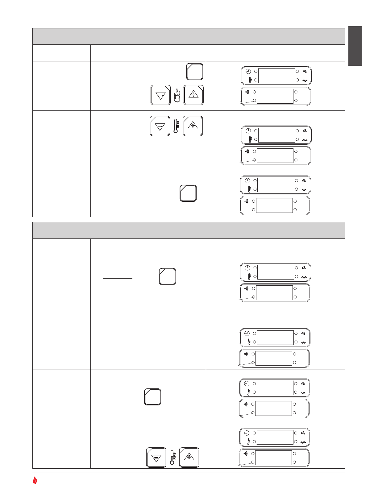
ACTIVATION/DEACTIVATION OF THE TEMPERATURE/TIME DISPLAY
Function Action Display
Activation/deactivati
on of the
tem perature/ time
display during
operation.
Press the SET key then press key 6.
Press the SET key twice in succession
and on the lower part
of the display the
code 03u will appear.
AL. C
AL. F
SET
OK
Set the code
Press key 2 to advance
through the sequence
of the codes:
(11= room temperature displayed; 12 = time
displayed).
Press key 1 to return through the sequence.
AL. C
AL. F
SET
OK
Confirm selection
and move to
programming the
first timer cycle
Press SET to confirm
AL. C
AL. F
SET
OK
DT2040038-00
3
SET
3
SET
Example: you want the room temperature to be shown during
operation: select code
11.
Example of display when stove is lit:
65
3
SET
21
0 3 U
OO
21
0 3 U
1 1
20oC
O N
4
PROGRAMMING THE TIMER’S FIRST CYCLE
Function Action Display
Access to
programming mode
Hold down the SET key
for five seconds
AL. C
AL. F
SET
OK
Activate/deactivate
the timer
The timer programming mode is
activated/deactivated by selecting the display
Cron (activated) or CroF (deactivated).
Press key 1 to select the desired display.
AL. C
AL. F
SET
OK
Confirm selection
Press the SET key to confirm.
AL. C
AL. F
SET
OK
Setting first cycle
automatic startup
time
Press key 2 to advance through the
timetable (10 minutes at a time).
Press key 1 to return through the
sequence.
AL. C
AL. F
SET
OK
3
SET
3
SET
For example, you want to activate the automatic startup and
shutdown for the desired period: Example of display.
The time previously input is shown:
For example, you want the stove to start up at 06:00
0 5 U
C r o n
FLASHING SCRIPT
0 5 U
C r o n
FLASHING SCRIPT
0 6 U
1 2 : 0 0
21
0 6 U
0 6 : 0 0
•
FLASHING LED
•
FLASHING LED
•
FLASHING LED
•
FLASHING LED
•
FLASHING LED
•
FLASHING LED
H07022850 / DT2000426 - 00
Page 26
English
26
SUPERIOR
®
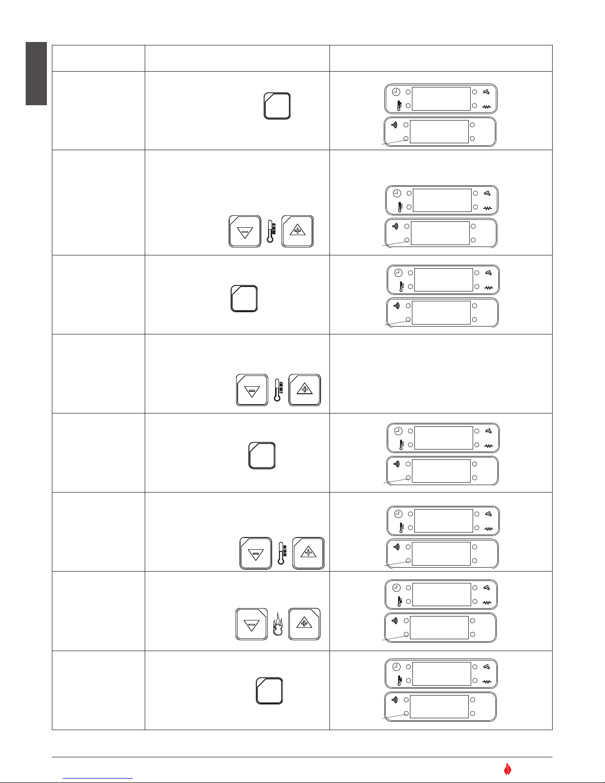
Function Action Display
Confirm selection
and move to next
setting
Press the SET key to confirm
AL. C
AL. F
SET
OK
Setting first cycle
automatic shutdown
time
Press key 2 to advance through the
timetable (10 minutes at a time).
Press key 1 to return through the
sequence.
AL. C
AL. F
SET
OK
Confirm selection
and move to next
setting
Press SET key to confirm
AL. C
AL. F
SET
OK
Timer
activated/deactivated
for any given day
Press key 2 to see the days of the week
Press key 1 to activate/deactivate
the timer function on
that day: ‘on’ or ‘off’
The chosen timetable will be confirmed (on) or
cancelled (oFF) for any given day
example LUon = active Monday
example LUoF = deactive Monday
Confirm selection
and move to next
setting
Press SET key to confirm
AL. C
AL. F
SET
OK
Select desired
temperature
Press key 2 to increase temperature
Press key 1 to lower temperature
AL. C
AL. F
SET
OK
Select power level
Press key 6 to increase the power
level: 1, 2, 3, 4, 5
Power level 2 is recommended
Press key 5 to
decrease the power
level: 5, 4, 3, 2, 1
AL. C
AL. F
SET
OK
Confirm selection
and move to
programming second
cycle
Press SET key to confirm
AL. C
AL. F
SET
OK
3
SET
3
SET
0 7 U
OO:OO
0 7
U
0 9 : 0 0
0 8
U
L U o n
21
21
For example, you want the first cycle of operation to shut down at
09.00:
3
SET
07oC
0 9 u 1
21
20oC
0 9 u 1
For example you want the room temperature to be 20°C
65
3
SET
21
20oC
0 9 u 2
3
SET
1 0 U
OO:OO
DT2040039-00
•
FLASHING LED
•
FLASHING LED
•
FLASHING LED
•
FLASHING LED
•
FLASHING LED
•
FLASHING LED
•
FLASHING LED
H07022850 / DT2000426 - 00
Page 27
English
27
SUPERIOR
®
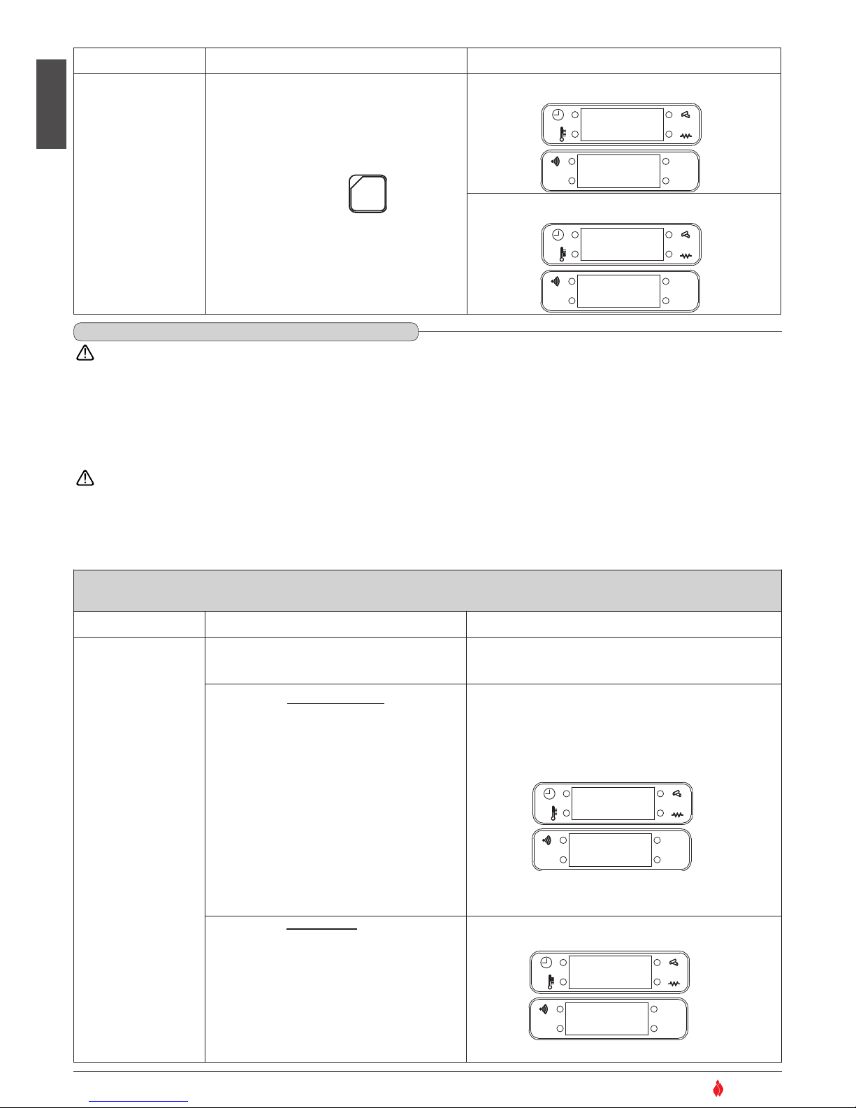
PROGRAMMING THE TIMER’S SECOND CYCLE
Function Action Display
Setting second cycle
automatic startup
time
Press key 2 to advance through the
timetable (10 minutes at a time)
Press key 1 to return
through the sequence
AL. C
AL. F
SET
OK
Confirm selection
and move to next
setting
Press the SET key to confirm
AL. C
AL. F
SET
OK
Setting second cycle
automatic shutdown
time
Press key 2 to advance through the
timetable (10 minutes at a time)
Press key 1 to return
through the sequence
AL. C
AL. F
SET
OK
Confirm selection
and move to next
setting
Press SET key to confirm
AL. C
AL. F
SET
OK
Timer
activated/deactivate
d on any given day
Press key 2 to see the days of the week
Press key 1 to activate/deactivate
the timer function on
that day: ‘on’ or ‘off’
The chosen timetable will be confirmed (on) or
cancelled (oFF) for any given day
example LUon = active Monday
example
LUoF = deactive Monday
Confirm selection
and move to next
setting
Press SET key to confirm
AL. C
AL. F
SET
OK
Select desired
temperature
Press key 2 to increase temperature
Press key 1 to lower
the temperature
progressively
AL. C
AL. F
SET
OK
Select power level
Press key 6 to increase the power
level: 1, 2, 3, 4, 5
Power level 2 is recommended.
Press key 5 to
decrease the power
level: 5, 4, 3, 2, 1
AL. C
AL. F
SET
OK
3
SET
3
SET
For example you want the stove to start up at 16:00
For example you want the second cycle to shut down at 19.30
21
1 0 U
16:OO
1 1
U
OO:OO
21
1 1 U
19:3O
1 2
U
L U o n
21
3
SET
07oC
1 3 u 1
21
For example you want the room temperature to be 20°C
20oC
1 3 u 1
65
3
SET
21
20oC
0 9 u 2
•
FLASHING LED
•
FLASHING LED
•
FLASHING LED
•
FLASHING LED
•
FLASHING LED
•
FLASHING LED
•
FLASHING LED
H07022850 / DT2000426 - 00
Page 28
English
28
SUPERIOR
®
During operation some parts of the stove (door, handle, ceramic parts) can reach high temperatures.
Remember to maintain the safety distances indicated previously.
Be careful, take all due precautions and always comply with the instructions.
If during operation smoke leaks from any part of the stove or the flue, shut the stove down immediately and ventilate the room. When the stove
has cooled, check for the cause of the leak and if necessary call in specialist personnel.
The stove is fitted with several safety devices to guarantee safe operation.
The safety devices are fitted to eliminate the risk of injury to people and pets and damage to property. Tampering or work carried
out by unauthorised personnel can jeopardise this function.
Possible warnings of problems
Simple operating problems can usually be resolved with the help of the following pages.
6.6 SAFETY DEVICES
DT2011439-00
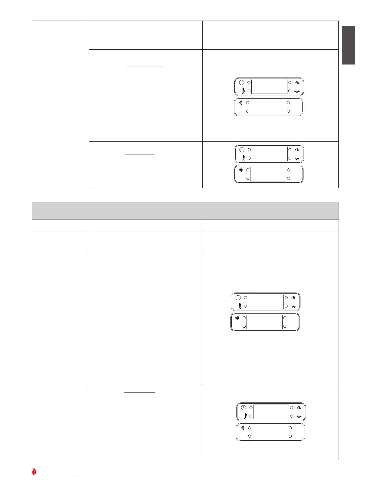
SMOKE CHAMBER PRESSURE
Sensor Description Display
Pressure switch
"
AL 1"
Connected to the exhaust outlet, it’s function is to
check the pressure inside the exhaust outlet allowing
operation of the stove in complete safety
WHEN ACTIVATED
If ideal operation conditions in the exhaust
outlet become altered (incorrect installation,
blockages or impediments in the flue, poor
maintenance, unfavourable weather conditions
such as persistent wind etc…) the sensor will
stop the power supply to the fuel-loading
chute, blocking the supply of fuel to the burner
and starting the shutdown process.
• In the left part of the display the message
"NO DEPR", will appear and in the right
half "AL1"
• The LED beside "ALF" will light up.
• After 60 seconds the alarm will sound (if
activated)
AL. C
AL. F
SET
OK
WHAT TO DO
•
Shut down the stove by holding the on/off key
down for several seconds (the alarm will stop);
• Wait until you are sure that combustion of
remaining pellets has stopped;
• Wait until the stove has cooled down, then
check for and remove whatever has caused the
safety system to be triggered.
Finally, after having cleaned the burner, restart
the stove by pressing the on/off key.
AL. C
AL. F
SET
OK
A L1
No
dEPr
•
LED LIGHTS
FLASHING SCRIPT
O
f f
12:OO
Sensor Description Display
Confirm selection.
Programming
complete. Exit from
programming mode.
Press SET key to confirm.
AL. C
AL. F
SET
OK
AL. C
AL. F
SET
OK
O
f f
12:OO
o n 4
20oC
If you have programmed the timer while the stove is unlit, the
display may look like this:
If you have programmed the timer while the stove is lit, the
display may look like this:
3
SET
H07022850 / DT2000426 - 00
DT2040040-00
Page 29
English
29
SUPERIOR
®
Sensor Description Display
Pressure switch
"
AL 3"
Its function is to check correct operation of the pressure
switch so that the stove can be used in all safety.
WHEN ACTIVATED
It activates during the “START” stage of the stove
(see “STARTING THE STOVE” table).
• If an anomaly is detected in the pressure switch,
the readout
"AL 3"
appears on the display
• In the right part of the display will appear the message
"AL 3"
.
• After 60 seconds the alarm will sound (if
activated).
AL. C
AL. F
SET
OK
WHAT TO DO
• Shut down the stove by holding the ON/OFF key
down for several seconds. (the alarm will stop).
• Call the After-Sales Service Centre.
AL. C
AL. F
SET
OK
DT2040096-00
A L3
O
f f
12:OO
FUEL TANK TEMPERATURE
Sensor Description Display
Thermostat with
automatic reset
"
AL 2"
Located on the pellet hopper, its function is to
prevent excessive temperature ranges.
WHEN ACTIVATED
If the pellet hopper temperature reaches critical
levels, the thermostat cuts off the power
supply to the fuel-loading auger, thereby
stopping the supply of pellets to the grate and
starting the stove shutdown process.
• In the left part of the display will appear the
message "HOT TEMP", and in the right part
"AL 2".
• The LED beside "AL C" will light up
• After 60 seconds the alarm will sound (if
activated).
AL. C
AL. F
SET
OK
WHAT TO DO
• Shut down the stove by holding the ON/OFF
key down for several seconds. (the alarm will
stop).
• Wait until you are sure that combustion of
any pellets remaining in the grate has
stopped.
• Finally, after having cleaned the grate restart
the stove by pressing the ON/OFF key. If the
anomaly continues call the After-Sales
Service Centre.
AL. C
AL. F
SET
OK
DT2040097-00
A L2
HOT
TEMP
•
LED LIGHTS
FLASHING SCRIPT
O
f f
12:OO
H07022850 / DT2000426 - 00
Page 30
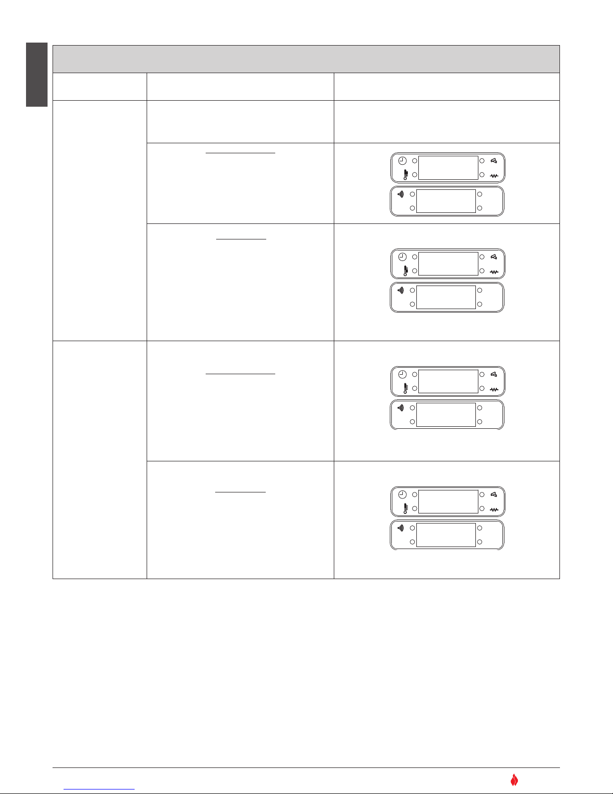
English
30
SUPERIOR
®
SMOKE TEMPERATURE SENSOR
Sensor Description Display
Smoke sensor
Connected to the electronic board, it constantly
monitors the running temperature allowing the
stove to operate in complete safety.
WHEN ACTIVATED
If the temperature exceeds the fixed safety limit
the board will stop the power supply to the
fuel-loading chute, thus depriving the burner of
fuel and starting the stove’s shutdown
process.
The message is accompanied by an alarm.
AL. C
AL. F
SET
OK
WHAT TO DO
• Shut down the stove by holding the ON/OFF
key down for several seconds.
• The alarm will stop.
• Wait until you are sure that combustion of
remaining pellets has stopped.
• Check for and remove whatever has triggered
the alarm
• After having cleaned the burner, restart the
stove by pressing the ON/OFF key.
AL. C
AL. F
SET
OK
Smoke sensor
disconnected
WHEN ACTIVATED
If the sensor becomes detached momentarily
and/or accidentally from its position, or if it is
not connected properly to the electronic board.
The problem will be indicated by the message
on the display and by an alarm.
AL. C
AL. F
SET
OK
WHAT TO DO
• Shut down the stove by holding the ON/OFF
key down for several seconds.
• The alarm will stop.
• Call the After-Sales Service Centre.
AL. C
AL. F
SET
OK
DT2040048-02
t e m p
Mass
o F F
12:00
C o n n
no
o F F
12:00
H07022850 / DT2000426 - 00
Page 31
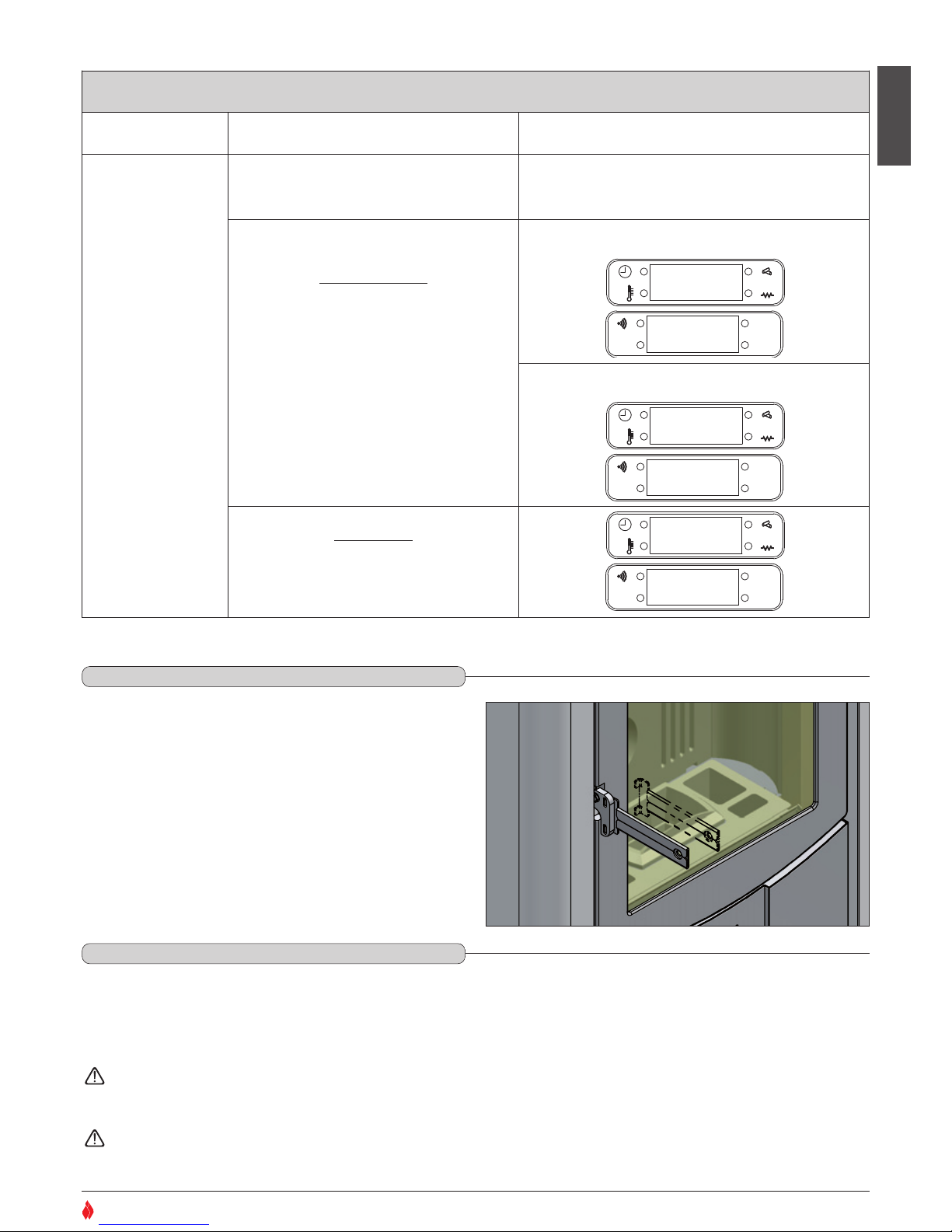
English
31
SUPERIOR
®
ROOM TEMPERATURE SENSOR
Sensor Description Display
Room sensor
Connected to the rear of the stove it constantly
monitors the temperature in the stove’s
immediate environs to ensure its operation in
complete safety.
WHEN ACTIVATED
If the sensor detaches itself momentarily
and/or accidentally from its position, the
problem does not require the immediate
shutdown of the stove, which will continue to
function normally at the chosen power level.
The problem will only be indicated if the
temperature display has been activated, in
which case a temperaure of 0°C will be
shown.
AL. C
AL. F
SET
OK
AL. C
AL. F
SET
OK
WHAT TO DO
Restore the sensor to its proper position;
If the temperature display has been activated
this will once again be shown.
AL. C
AL. F
SET
OK
DT2040049-00
Example of display if temperature display is activated:
Example of display if time display is activated:
During operation the door must remain closed. It is to be opened
only when the stove has been shut down and cooled for the
carrying out of maintenance.
Use the door handle tool provided in the kit to open the door, using
it as shown in the picture below.
DT2030633-00
6.7 OPENING THE DOOR - Fig. 33
DT2010087-04
6.8 DISPOSAL OF ASHES
DT2010049-04
o n 4
00
o
C
o n 4
12:3O
o n 4
26
o
C
Ash from natural (non-treated) wood burned in stoves or open fireplaces is composed mainly of calcium, silicon, potassium and
magnesium oxides. The ashes can therefore be used as a fertiliser for plants or in the garden, albeit not exceeding 2.6 kg per 10m
2
annually
The ashes should be placed in a metal container with a sealed cover. The sealed container should be placed on a noncombustible surface at a safe distance from combustible materials until the cinders have been completely extinguished.
Only when they have been fully extinguished can the ashes be thrown away with organic waste, assuming that nails or other
non-organic material are not present.
Fig. 33
H07022850 / DT2000426 - 00
Page 32
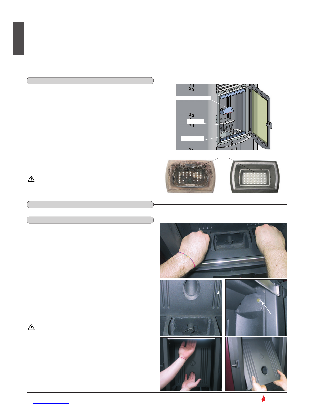
Every two days, check the ash drawer to see if it needs emptying. For the disposal of ashes see section 6.8.
English
32
DT2010057-02
Pursuant to current regulations on the safety of electrical equipment, you must contact a Superior After-Sales Service Centre or a qualified
electrician for all and any work connected with installation, maintenance or servicing that involves access to electrical parts.
Maintenance is to be considered compulsory for correct and efficient stove operation. If maintenance is not carried out with the recommended
frequency, stove performance could suffer. The manufacturer will not be responsible for stove deterioration or malfunction if due to poor
maintenance.
All maintenance work (cleaning, any replacements, etc.) must be carried out when the stove is shutdown and cold.
Do not use materials that could scratch or damage the glass, since scratches could become cracks. Under no circumstances use abrasive
substances.
SUPERIOR
®
7.0 MAINTENANCE
DT2010197-01
7.1 CLEANING THE GRATE AND THE GRATE SUPPORT - Fig. 34-35
DT2010156-04
7.2 CLEANING THE ASH DRAWER
DT2010100-03
7.3 CLEANING THE FIREBOX – Fig. 34 / 40
DT2010199-03
DT2030632-00
Fig. 34
GRATE BAFFLE PLATE
GRATE
H07022850 / DT2000426 - 00
ASH DRAWER
IGNITION HOLE
DT2030239-02
Fig. 35
DT2030289-00
Fig. 37
DT2030290-00
Fig. 38
DT2030291-00
Fig. 39
DT2030292-00
Fig. 40
DT2030288-00
Fig. 36
Clean the grate area periodically (approx. once every two days) and
whenever the stove is to be lit:
• Remove the grate baffle plate and lift out the grate.
• Remove any ash or other material that may have built up, taking
particular care to free any clogged holes using a sharp pointed
tool.
• Make sure the “ignition hole”, located on the rear of the grate, is
kept clean.
• Check the grate support and remove any ash.
The frequency of cleaning depends on how much the stove is used
and the quality of the fuel
After cleaning and before lighting the stove, check that the
grate is correctly inserted and pushed back towards the
lower rear baffle. Refit the grate baffle plate.
The firebox should be cleaned once a week as follows:
• remove the grate and the ash drawer (Fig. 34).
• Remove the internal baffle plate by raising it slightly using the
flaps as handles, if necessary loosening the two screws fixing the
side baffle plates (Fig. 37 - 38), then rotate it and tilt it in order to
slide it out of the firebox (Fig. 39 - 40).
• Use a vacuum cleaner to remove any ash from the firebox.
• Having cleaned the firebox thoroughly, replace the parts in the
reverse order to above, paying particular attention to the
positioning of the internal baffle plate: it should sit snugly on the
catches on the sides of the firebox (the two catches must remain
in front of the baffle plate).
This type of cleaning requires a vacuum cleaner suitable for
holding ash.
Page 33
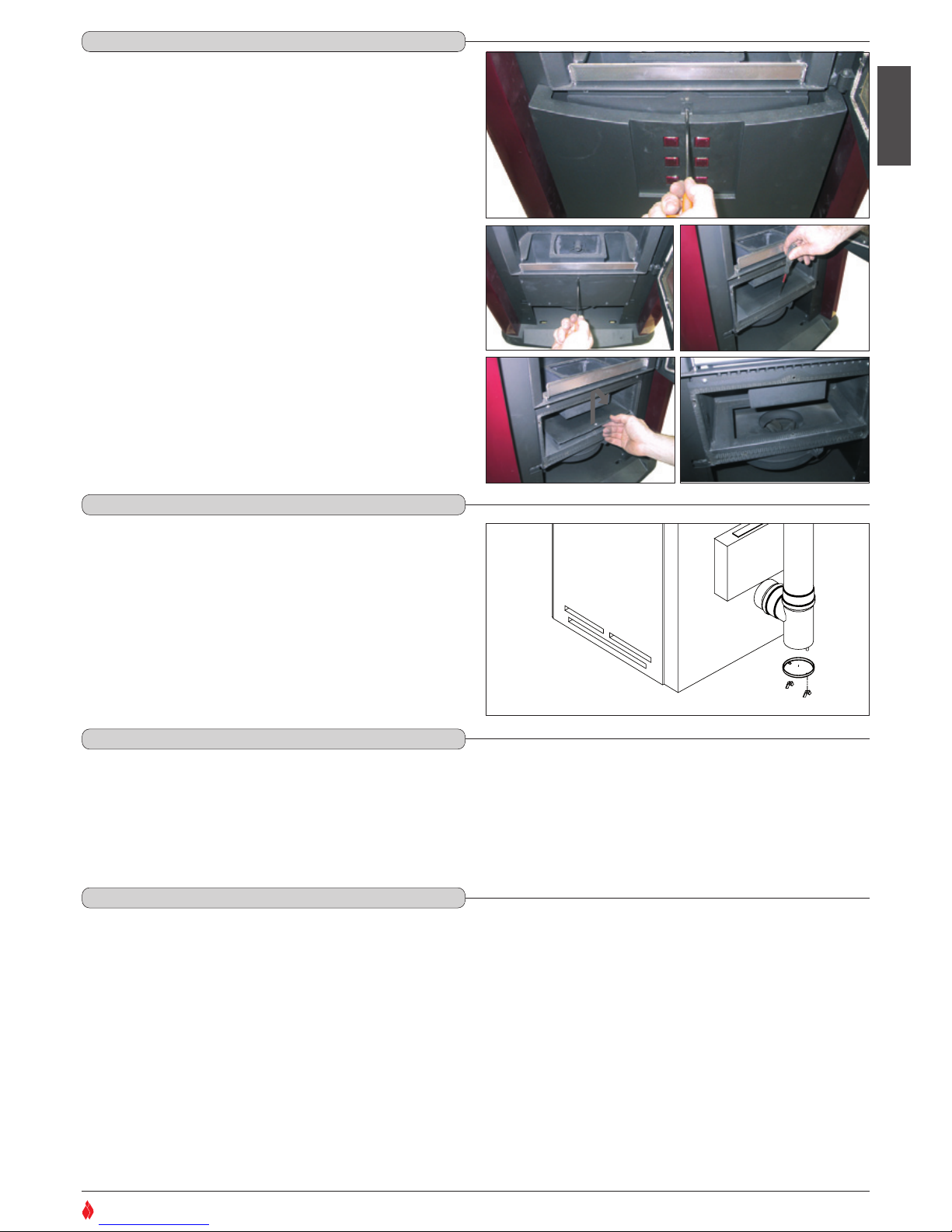
When cleaning the enamelled metal parts of the product use a soft cloth moistened with water.
NEVER CLEAN METALLIC PARTS USING ALCOHOL, SOLVENTS, PETROLEUM-BASED PRODUCTS, ACETONES OR OTHER DEGREASING OR
ABRASIVE SUBSTANCES.
In the event of such substances being used the manufacturer will not be responsible for any damage caused.
Discolouration of metallic parts may be the result of misuse.
The ceramic cladding must first be cleaned with a soft dry cloth before using any detergent (even mild detergent).
Products are available on the market which are suitable for cleaning ceramics as well as concentrated products for cleaning porcelain. These will
remove oil, ink, coffee and wine stains, etc.
NEVER SOAK THE CERAMIC CLADDING OR CLEAN IT WITH COLD WATER WHEN IT IS STILL HOT AS THE THERMAL SHOCK COULD CAUSE IT TO CRACK.
English
Once a year clean the smoke chamber as follows:
• Remove the screw which secures the lower front cladding, then
raise the cladding element slightly and pull it towards you (Fig.
41).
• Remove the seven screws which secure the front cover of the
chamber (Fig. 42).
• Remove the screws which secure the smoke duct cover, then lift
it slightly and take it out by pulling it towards you (Fig. 43 – 44).
• Use a vacuum cleaner to remove any ash and carbon deposits
which can accumulate in the chamber, paying particular attention
not to damage the blades of the fan (Fig. 45).
• After cleaning the chamber thoroughly, refit the cover and if
necessary replace the gasket.
IIn order to get the most from your product we recommend that this
maintenance be carried out on a monthly basis.
Remove the plug from the Tee and clean the pipes.
If necessary, particularly on the first few occasions, we recommend
calling in a qualified technician.
DT2031151-00
Fig. 46
33
SUPERIOR
®
7.4 CLEANING THE SMOKE CHAMBER - Fig. 41 / 45
DT2010200-01
7.5 CLEANING THE FLUE SYSTEM - Fig. 46
DT2010092-03
7.7 CLEANING THE ENAMELLED METAL PARTS
DT2010061-03
H07022850 / DT2000426 - 00
Fig. 41
Fig. 42
DT2030295-00
Fig. 43
DT2030296-00
Fig. 44
DT2030297-00
Fig. 45
DT2030294-00
DT2030293-00
7.6 CLEANING THE CERAMIC CLADDING
DT2010059-03
Page 34
The glass should be cleaned when cold using ammonia-based degreasing agents and not corrosive substances such as solvents.
If the appliance is very slow to heat up in the ignition phase due to fuel that isn’t completely dry, this is likely to cause a build-up of tar on the glass. This
will eventually burn off when the secondary air supply is opened (if the appliance is equipped accordingly) or when the appliance is operating at full capacity.
If the tar is left to build up over a long period it will require more effort to remove
We therefore recommend that the glass be cleaned daily before lighting the stove.
Do not use any material that could scratch or spoil the glass, as scratches may develop into cracks or breaks.
The stove is fitted with a 4mm thick glass panel, resistant to thermal shock up to 750ºC; the glass can only be broken by heavy impact or misuse. Do not
slam the door or hit the window. In case of breakage replace only with a Gruppo Piazzetta spare part. To replace, proceed as follows:
• wear protective gloves;
• remove the door and lie it flat;
• loosen the screws visible on the inside of the door;
• remove the frame and glass carefully;
• if the fibreglass seal and glazing bead have deteriorated, replace them;
• change the glass panel then replace the frame, tightening the screws carefully but not excessively;
• remount the door.
If other problems occur, consult your nearest retailer.
To change the battery proceed as follows: using a small Philips head screwdriver, remove the screw on the back of the handset. Then holding it
upside down remove the back casing. Replace the battery (type A23 12V) being careful not to reverse the polarity (the battery type and polarity
are shown on the back of the handset). Close the handset and dispose of the old battery in the appropriate way.
If the problem persists contact your nearest retailer or Centre for Technical Assistance.
Any cleaning or maintenance work must be carried out after the CURRENT HAS BEEN SWITCHED OFF.
The stove is fitted with fans (smoke extractor and heating) positioned at the bottom rear of the stove. Any build-up of dust or ash on the blades can unbalance
them resulting in noise during operation.
It is necessary to have the fans cleaned annually. Since such an operation involves dismantling certain parts of the stove, have the cleaning carried out only
by a Piazzetta Service Centre or other qualified persons.
When shutting the stove down for the summer, proceed as follows:
• remove all pellets from the hopper and feeding auger;
• carefully clean the grate, the grate support, the firebox and the ash drawer;
• clean the flue thoroughly: contact a professional chimneysweep for this purpose;
• clean all dust, cobwebs, etc. from the area behind the inner lining panels once a year, in particular the fans.
• Disconnect the power cable from the power supply.
The following maintenance should be carried out ONCE A YEAR and is necessary to ensure efficient and safe stove operation.
• Clean the firebox thoroughly.
• Clean and inspect the flue.
• Check the condition of seals and gaskets.
• Clean mechanical and moving parts (motors and fans).
• Check electrical and electronic components.
English
34
SUPERIOR
®
7.8 CLEANING THE GLASS (DAILY)
DT2010062-04
7.9 REPLACING THE WINDOW
DT2010093-05
7.10 REPLACING THE REMOTE CONTROL BATTERY
DT2010094-00
7.11 CLEANING THE FANS
DT2010095-06
7.12 WHEN NOT IN USE
DT2010096-03
7.13 EXTRAORDINARY MAINTENANCE
DT2010097-03
H07022850 / DT2000426 - 00
Page 35
English
35
SUPERIOR
®
Some of the problems indicated below may be resolved by following the instructions. All work must be carried out when the
appliance is cold and disconnected from the electricity supply (pull out the plug).
Authorised qualified persons must be contacted, in accordance with current regulations, whenever it is necessary to work on parts
inside the cladding or the firebox in order to resolve the problem. It is therefore recommended that only “Gruppo Piazzetta S.p.A.”
authorised Service Centres be contacted. Whenever authorised Service Centre personnel carry out work, they must show an identity
card issued by Gruppo Piazzetta S.p.A. on which the following are printed: name of the Service Centre, stamp and signature of the
company and the period of validity of the actual document.
Unauthorised tampering with the appliance or the use of other than original spare parts not only creates situations of risk for
operator safety, but invalidates the warranty and relieves the manufacturer from all liability.
8.0 TROUBLESHOOTING
DT2011482-00
PROBLEM CAUSE SOLUTION
The control panel display is not lit
The stove has no power supply
Check that the power lead is plugged
into the wall and the stove
Defective power lead
Replace the power lead (use only
original spares)
Fuses blown
Check the fuses in both the plug and
on the electronic board, replacing
them if necessary. If problem persists
call an electrician
Defective control panel
Replace the control panel (use only
original spares)
Defective flat cable
Replace flat cable (use only original
spares)
Defective electronic board
Replace electronic board (use only
original spares)
External pressure reader warning
"
AL 1
" "
NO DEPR
"
Blocked flue
Check and clean the flue
Broken smoke extractor
Replace the motor (use only original
spares)
Flue system too long
Verify correct installation (see section 5)
Deteriorated door or exhaust system
linings
Check all washers and linings
Pipe insulation blocked
Dismantle and clean
Silicone piping blocked or broken
Check and/or replace piping
Defective electronic board
Replace electronic board (use only
original spares)
Door open
Control if the door is closed
H07022850 / DT2000426 - 00
Page 36
English
36
SUPERIOR
®
PROBLEM CAUSE SOLUTION
Fuel tank automatic reset thermostat
warning
"
AL 2
" "
Hot tEMP
"
Blocked flue
Check and clean the flue
Burner requires cleaning
Clean burner (see section 7.1)
Defective thermostat
Replace thermostat (use only original
spares)
Badly positioned thermostats
Check positioning of sensor
Defective electronic board
Replace electronic board (use only
original spares)
Defective fan
Check the fan; replace if necessary
(use only original spares)
Failed ignition "
NO ACC
"
Fuel tank empty
Refuel
Burner requires cleaning
Clean burner (see section 7.1)
Required operating temperature not
reached
Empty burner and restart
Defective pilot light
Replace pilot light (use only original
spares)
Defective electronic board
Replace electronic board (use only
original spares)
Pressure switch "
AL 3
" malfunction
Faulty pressure switch
Replace the pressure switch (use
only original spares).
No power supply to the auger
Check the electrical connections
(contact a Superior After-Sales
Service Centre or an authorised
person).
H07022850 / DT2000426 - 00
Page 37
English
37
SUPERIOR
®
PROBLEM CAUSE SOLUTION
Exhaust outlet temperature warning
"
MASS tEMP
"
Blocked flue
Clean flue
Defective electronic board
Replace electronic board (use only
original spares)
Defective sensor
Replace sensor (use only original
spares)
Badly positioned sensor
Check positioning and connection of
sensor (see electrical diagram)
Incorrect settings input
Check settings
Smoke sensor disconnected
"
NO CONN"
Bad connection from 2-pin terminal
to electronic board
Check positioning and connection
of sensor (see electrical diagram)
Defective electronic board
Replace electronic board (use only
original spares)
Badly positioned sensor
Check connections
Stove runs for 9-10 minutes then
goes out
Exhaust fumes have not reached
required temperature
Retry and if problem persists contact
an authorised technician
Heat sensor badly connected
Check cabling and connections
Blocked flue
Clean flue
Failed ignition
See "
NO ACC
"
Defective electronic board
Replace electronic board (use only
original spares)
Fuel-loading system blocked
Empty fuel tank; check and clean fuelloading system
H07022850 / DT2000426 - 00
Page 38
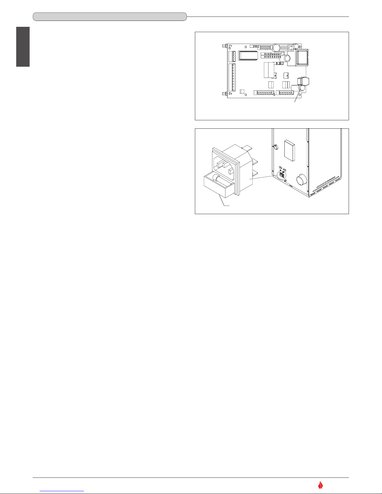
SUPERIOR
®
English
Electronic board fuse.
Unscrew the cartridge fuse or safety plug from the electronic board and
replace with a similar one.
Motherboard fuse type: F4AL250V
Fuse on the IEC power socket.
Draw out the fuse carrier and replace the fuse with the spare to be
found inside the small drawer.
Type: F4AH250V
Tappo p o rt a fusibile
Cartridge fuse/safety plug
Motherboard
Cassettino porta fusibile
Fuse carrier drawer
Fig. 47
Fig. 48
DT2030896-00
DT2030897-00
38
8.1 REPLACING THE FUSES
DT2010557-02
H07022850 / DT2000426 - 00
Page 39

SUPERIOR
®
DICHIARAZIONE DI CONFORMITÀ
DECLARATION OF CONFORMITY
Il sottoscritto, rappresentante il seguente costruttore
The undersigned, representative of the following manufacturer
Gruppo Piazzetta S.p.A.
Via Montello, 22
31010 Casella D'Asolo (TV) - ITALY
DICHIARA che l’apparecchiatura descritta in appresso:
DECLARES that the product:
Descrizione
Description
PELLETS STOVES
Modelli
Models
SOFIA
è conforme alle disposizioni legislative che traspongono le seguenti direttive:
• direttiva 89/336 CEE (Direttiva EMC) e successivi emendamenti
• direttiva 73/23 CEE (Direttiva Bassa Tensione) e successivi emendamenti
is in accordance with the following Directives:
• 89/336 EEC Directive (EMC Directive) and subsequent amendments
• 73/23 EEC Directive (Low Voltage Directive) and subsequent amendments
e che sono state applicate tutte le norme e/o specifiche tecniche di seguito indicate
and that all the following standards have been applied
EN 55014-1 (2000) + EN 55014-1/A1(2001) + EN 55014-1/A2(2002);
EN 61000-3-2 (2000); EN 61000-3-3 (1995) + EN 61000-3-3/A1 (2001)
EN 55014-2 (1997) + EN 55014-2/A1 (2001)
EN 60335 1 (1994); EN 60335 1/Ec (1995) ; EN 60335-1/A11 (1995) ; EN 60335-1/A1 (1996); EN 60335-1/A12 (1996); EN 60335-1/A13
(1998); EN 60335-1/A14 (1998); EN 60335-1/A15 (2000); EN 50165 (1997)
Ultime due cifre dell’anno in cui è affissa la marcatura CE
____05___________
Last two figures of the year of the CE marking
Luogo
__Casella D'Asolo (TV)____
Place
Data
01 / 07 / 2005
Date
Firma
Sign
(nome e funzione)
(name and title)
DT2010101-01 COPIA / COPY
SUPERIOR
®
39
H07022850 / DT2000426 - 00
Page 40

Gruppo Piazzetta S.p.A. Technical Department - Cod. H07022850/DT2000426 Rev. 00 (01/2009)
Product serial number, to be quoted when requesting service
from the Gruppo Piazzetta After-Sales Service Centre.
Via Montello, 22
31011 Casella d’Asolo (TV) - ITALY
Tel. +39.04235271 - Fax +39.042355178
www.superiorcaminetti.it
e-mail:[email protected]
SUPERIOR
®
 Loading...