

Page 1
P/N 506009-02 Rev. B 06/2011
AVERTISSEMENT : Assurez-vous de bien suivre les
instructions données dans cette notice pour réduire au
minimum le risque d’incindie ou d’explosion ou pour
éviter tout dommage matériel, toute blessure ou la mort.
WARNING: If the information in these instructions
is not followed exactly, a fire or explosion may
result, causing property damage, personal injury,
or death.
WARNING /AVERTISSEMENT/AVISO
• HOT GLASS WILL CAUSE
BURNS.
• DO NOT TOUCH GLASS
UNTIL COOLED.
• NEVER ALLOW CHILDREN
TO TOUCH GLASS.
• UNE SURFACE VITRÉE CHAUDE
PEUT CAUSER DES BRÛLURES.
• LAISSER REFROIDIR LA SURFACE
VITRÉE AVANT D'Y TOUCHER.
• NE PERMETTEZ JAMAIS À UN ENFANT
DE TOUCHER LA SURFACE VITRÉE.
• EL VIDRIO CALIENTE
CAUSARÁ QUEMADURAS.
• USTED DEBE NUNCA
TOCAR EL VIDRIO CALIENTE.
• LOS NIÑOS DEBEN NUNCA
TOCAR EL VIDRIO.
- Do not store or use gasoline or other flammable
vapors and liquids in the vicinity of this or any other
appliance.
- WHAT TO DO IF YOU SMELL GAS:
• Do not try to light any appliance.
• Do not touch any electrical switch; do not use any
phone in your building.
• Immediately call your gas supplier from a
neighbor’s phone. Follow the gas supplier’s
instructions.
• If you cannot reach your gas supplier, call the fire
department.
- Installation and service must be performed by a
qualified installer, service agency or the gas supplier.
- Ne pas entreposer ni utilizer d’essence ni d’autres vapeurs
ou liquides inflammables dans le voisinage de cet appareil
ou de tout autre appareil.
- QUE FAIRE SI VOUS SENTEZ UNE ODEUR DE GAZ :
• Ne pas tenter d’allumer d’appareil.
• Ne touchez à aucan interrupteur. Ne pas vous servir des
téléphones se trouvant dans le bâtiment où vous trouvez.
• Appelez immédiatement votre fournisseur de gaz depuis
un voisin. Suivez les instructions du fournisseur.
• Si vous ne pouvez rejoindre le fournisseur de gaz,
appelez le service des incindies.
- L’installation et l’entretien doivent être assurés par un
installateur ou un service d’entretien qualifié ou par le
fournisseur de gaz.
This manual is one of a set of two supporting this product.
Refer to P/N 506010-02 for Care and Operation Instructions.
Ce manuel est disponible en francais, simplement
en faire la demande. Numéro de la pièce 506223-19.
INSTALLER: Leave this manual with the appliance.
CONSUMER: Retain this manual for future reference.
INSTALLATEUR : Laissez cette notice avec l'appareil.
CONSOMMATEUR : Conservez cette notice pour
consultation ultérieure.
INSTALLATION INSTRUCTIONS
B-Vent Gas Fireplaces
SLBV 35/40 Models
MODELS
SLBV-35NM
SLBV-35PM
ITS Report No. 100017854
Please read and understand these instructions
MILLIVOLT:
SLBV-40NM
SLBV-40PM
BEFORE starting installation.
ELECTRONIC:
SLBV-35NE
SLBV-40NE
Page 2

SUPERIOR® B-VENT GAS FIREPLACES • MODELS SLBV-35, SLBV-40 • INSTALLATION INSTRUCTIONS
TABLE OF CONTENTS
Packaging .........................................Page 2
Introduction ......................................Page 2
General Information ..........................Page 2
Gas Pressure Requirements ..............Page 4
Orifice Sizes ......................................Page 4
Gas Valve Diagrams ..........................Page 4
Requirements for the Commonwealth
of Massachusetts .......................Page 4
New York City Approval .....................Page 4
Cold Climate Insulation .....................Page 5
Location ............................................ Page 5
Vent Termination Clearances:
Multiple Terminations.....................Page 6
Gas Vent Rule ................................Page 6
Minimum Clearances to Combustibles:
Appliance and Vent Clearances ......Page 7
Hearth Extension ............................Page 7
Wall Finishes / Surrounds /
Mantels .......................................Page 7
Pre-Installation Steps (Remove
Glass Enclosure Panel) ...............Page 8
Typical Installation Sequence ............Page 8
Detailed Installation Steps:
Step 1. Construct Appliance
Framing ............................Page 8
Fireplace and Framing
Specifications ...................Page 9
Step 2. Route the Gas Line ..............Page 11
Step 3. Install Venting System and
Exterior Termination .........Page 11
Step 4. Install Field Wiring ..............Page 12
Wiring Diagrams .................Page 13
Step 5. [Optional] Install Outside
Combustion Air Kit ............Page 14
Installation Accessories ......Page 14
Step 6. Connect the Gas Line ..........Page 15
Step 7. Verify Appliance
Operation .........................Page 16
Step 8. Install Volcanic Stone, Glowing
Embers, and Logs ........... Page 17
SLBV-35 Log Placement .....Page 18
SLBV-40 Log Placement .....Page 19
Step 9. Install the Glass Enslosure
Panel ...............................Page 20
Step 10. Burner Air Shutter
Adjustments .....................Page 20
Step 11. Perform Spillage Test ..........Page 22
Manually-Reset Safety Limit
Switch ..............................Page 22
Step 12. Install Hood .........................Page 23
Step 13. Finishing Requirements ......Page 23
Step 14.
Warnings ...................................... Page 24
Gas Conversion Kits .........................Page 25
2
Attach Safety-in-Operation
PACKAGING
The assembled vented gas replace is packaged
with the following items:
1 - One log set located in rebox area.
2 - One envelope containing the literature
package which consists of the care and
operations manual, installation instructions, safety-in-operation warning labels
and warranty; envelope is located in the
control compartment.
3 - One hood located behind the glass enclo-
sure panel assembly.
4 - One bag of decorative volcanic stone located
in the lower control compartment.
5 - One bag of glowing embers located in the
lower control compartment.
INTRODUCTION
The Millivolt appliances have a millivolt gas
control valve with piezo ignition system.
The Electronic appliances have a battery
backed-up electronic intermittent pilot ignition
system. No external electrical power is required
to operate these appliances; however, 120V
AC is recommended (see Step 4, “Install Field
Wiring,” on Page 12).
Use Only These Approved Vent Components:
These vented gas fireplaces are designed for
residential applications. They must be installed
with approved Type-B double-wall vent pipe
systems and a listed vent termination routed
to the outside atmosphere. Use only the proper
size listed below.
• 4" B-Vent for 35" models and 5" B-Vent for
40" models.
GENERAL INFORMATION
WARNING
B-Vent appliances are
not designed to operate
in negatively pressured
environments (pressure within
the home is less than pressures
outside). Significant negatively
pressured environments caused
by weather, home design, or
other devices may impact the
operation of these appliances.
Negative pressures may result
in poor flame appearance,
sooting, damage to property
and/or severe personal
injury. Do not operate these
appliances in negatively
pressured environments.
WARNING
Young children should be carefully supervised when they are
in the same room as the appliance. Toddlers, young children
and others may be susceptible
to accidental contact burns.
A physical barrier is recommended if there are at risk
individuals in the house. To
restrict access to a fireplace
or stove, install an adjustable
safety gate to keep toddlers,
young children and other at
risk individuals out of the room
and away from hot surfaces.
AVERTISSEMENT
Les jeunes enfants devraient être
surveillés étroitement lorsqu’ils
se trouvent dans la même pièce
que l’appareil. Les tout petits,
les jeunes enfants ou les adultes
peuvent subir des brûlures s’ils
viennent en contact avec la surface chaude. Il est recommandé
d’installer une barrière physique
si des personnes à risques habitent la maison. Pour empêcher
l’accès à un foyer ou à un poêle,
installez une barrière de sécurité; cette mesure empêchera les
tout petits, les jeunes enfants et
toute autre personne à risque
d’avoir accès à la pièce et aux
surfaces chaudes.
Children and adults should be alerted to
the hazards of high surface temperature
and should stay away to avoid burns or
clothing ignition.
Les enfants et les adultes devraient
être infor-més des dangers que posent
les températures de surface élevées
et se tenir à distance afin d’éviter des
brûlures ou que leurs vêtements ne
s’enflamment.
DO NOT ATTEMPT TO ALTER OR
MODIFY THE CONSTRUCTION OF THE
APPLIANCE OR ITS COMPONENTS. ANY
MODIFICATION OR ALTERATION MAY
VOID THE WARRANTY, CERTIFICATION,
AND LISTINGS OF THIS UNIT.
Page 3
SUPERIOR® B-VENT GAS FIREPLACES • MODELS SLBV-35, SLBV-40 • INSTALLATION INSTRUCTIONS
GENERAL INFORMATION
(continued)
WARNING
Improper installation, adjustment, alteration, service or
maintenance can cause injury
or property damage. Refer to
this manual. For assistance or
additional information consult
a qualied installer, service
agency or the gas supplier.
WARNING
Failure to comply with these
installation instructions will
result in an improperly installed
and operating appliance, voiding its warranty. Any change to
this appliance and/or its operating controls is dangerous.
WARNING
Clothing or other ammable
material should not be placed
on or near the appliance.
AVERTISSEMENT
On ne devrait pas placer de
vêtements ni d’autres matières
inammables sur l’appareil ni à
proximité.
WARNING
Any safety screen or guard
removed for servicing the appliance must be replaced prior to
operating the appliance.
AVERTISSEMENT
Tout écran ou protecteur retiré
pour permettre l’entretien de
l’appareil doit être remis en
place avant de mettre l’appareil
en marche.
WARNING
Improper installation or use
of this appliance can cause
serious injury or death from
re, burns, explosion or
carbon monoxide poisoning.
Note: Installation and repair should be done
by a qualified service person. The appliance
should be inspected before use and at least
annually by a professional service person.
More frequent cleaning may be required due
to excessive lint from carpeting, bedding
material, etcetera. It is imperative that control
compartments, burners and circulating air
passageways of the appliance be kept clean.
Remarque : L’installation et la réparation devrait être confiées à un technicien
qualifié. L’appareil devrait faire l’objet
d’une inspection par un technicien professionnel avant d’être utilisé et au moins
une fois l’an par la suite. Des nettoyages
plus fréquents peuvent être nécessaires si
les tapis, la literie, et cetera produisent
une quantité importante de pous-sière.
Il est essentiel que les compartiments
abritant les commandes, les brûleurs
et les conduits de circulation d’air de
l’appareil soient tenus propres.
Do not use these appliances if any part
has been under water. Immediately call a
qualified, professional service technician
to inspect the appliance and to replace
any parts of the control system and any
gas control which have been under water.
Ne pas utiliser cet appareil s’il a été
plongé, même partiellement, dans
l’eau. Appeler un technicien qualifié
pour inspecter l’appareil et remplacer
toute partie du système de commande
et toute commande qui a été plongée
dans l’eau.
Only trim kit(s) supplied by the manufacturer
shall be used in the installation of this appliance.
Seules les trousses de garniture fournies
par le fabricant doivent être utilisées pour
l’installation de cet appareil.
These appliances comply with National Safety
Standards and are tested and listed by ITS
(Report No. 100017854) to ANSI Z21.50 (in
Canada, CSA-2.22) and to CAN/CGA-2.17-M91
in both USA and Canada (latest editions at time
of manual publication) as vented gas replaces.
Both millivolt and electronic versions of
these appliances are listed by ITS for installation in bedrooms in the United States (not
approved in Canada).
These appliances must not be connected to a
chimney or flue serving a separate solid fuel
burning appliance.
Installation must conform to local codes, or, in
the absence of local codes, with the National
Fuel Gas Code, ANSI Z223.1/NFPA 54 (latest
edition), or the Natural Gas and Propane Installation Code, CAN/CSA B149.1 (latest edition).
The appliance, when installed, must be electri-
cally grounded and wired in accordance with
local codes or, in the absence of local codes, with
the USA National Electrical Code, ANSI/NFPA
70 (latest edition) or, in Canada, the Canadian
Electrical Code, CSA C22.1 (latest edition).
Provide adequate clearances around air open-
ings and adequate accessibility clearance for
service and proper operation. Never obstruct
the front opening of the appliance.
These appliances are designed to operate on
natural or propane gas only. The use of other
fuels or combination of fuels will degrade
the performance of this system and may be
dangerous.
These fireplaces are designed as supplemental
heaters; therefore, it is advisable to have an
alternate primary heat source when installed
in a dwelling.
MILLIVOLT MODELS: The millivolt appliances
are manually controlled and feature a spark
igniter (piezo) that allows the appliance's pilot
gas to be lit without the use of matches or batteries. This system provides continued service
in the event of a power outage.
ELECTRONIC MODELS: The electronic appliances are manually controlled and feature an
electronic intermittent pilot ignition system.
External electrical power is required to operate
these units.
ALL MODELS: Both millivolt and electronic
models come standard with a manuallymodulated gas valve; flame appearance and
heat output can be controlled at the gas valve.
BTU input rates for all models are listed in
Table 1, below.
Input (BTU/hr) Manually-Modulated
Gas Valves (all models)
Models
SLBV-35
SLBV-40
Table 1
Input Rate (BTU / HR)
Nat. Gas Prop. Gas
17,000 high
13,000 low
22,000 high
17,000 low
17,000 high
14,000 low
20,000 high
15,500 low
3
Page 4
SUPERIOR® B-VENT GAS FIREPLACES • MODELS SLBV-35, SLBV-40 • INSTALLATION INSTRUCTIONS
GAS PRESSURE REQUIREMENTS
(All Models)
Tables 2 and 3 show the appliances' inlet and
manifold gas pressure requirements:
Inlet Gas Supply Pressure
(All models)
Fuel # Minimum Maximum
Natural Gas
Propane
4.5" WC
(1.12 kPa)
11.0" WC
(2.74 kPa)
Table 2
Manifold Gas Supply Pressure
(All models)
Fuel # Low High
Natural
Gas
Propane
(Lo) 2.2" WC
(0.55 kPa)
(Lo) 6.3" WC
(1.57 kPa)
Table 3
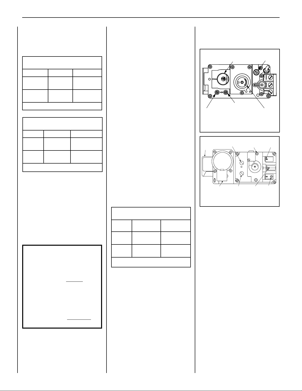
Test gauge connections are provided on the
front of the gas control valve, identied IN for
the inlet and OUT for the manifold side (see
Figures 1 and 2).
Propane tanks are at pressures that will cause
damage to valve components. Verify that the
tanks have step-down regulators to reduce the
pressure to safe levels.
These appliances must be isolated
from the gas supply piping system (by
closing their individual manual shut-off
valve) during any pressure testing of
the gas supply piping system at test
pressures equal to or less than 1/2 psig
(3.5 kPa).
These appliances and their individual
shut-off valves must be disconnected
from the gas supply piping system
during any pressure testing of that
system at pressures greater than 1/2
psig (3.5 kPa).
4
10.5" WC
(2.61 kPa)
13.0" WC
(3.23 kPa)
(Hi) 3.5" WC
(0.87 kPa)
(Hi) 10.0" WC
(2.49 kPa)
ORIFICE SIZES
Sea Level to High Altitude
(All Models)
These appliances are tested and approved for
installation at elevations of 0–4500 feet (0–1372
meters) above sea level using the standard
burner orice sizes (marked with an asterisk
(*) in Table 4, below).
For elevations above 4500 feet, contact your
gas supplier or a qualified service technician.
Deration
At higher elevations, the amount of BTU fuel
value delivered must be reduced by either:
• using gas that has been derated by the gas
company,
• changing the burner orice to a smaller size
as regulated by the local authorities having
jurisdiction and by the (USA) National Fuel Gas
Code NFPA 54/ANSI Z223.1 - latest edition or,
in Canada, the CAN/CSA-B149.1 codes - latest
edition.
Install the appliance according to the regulations
of the local authorities having jurisdiction and,
in the USA, the National Fuel Gas Code NFPA
54 / ANSI Z223.1 - latest edition or, in Canada,
the CAN/CSA-B149.1 - latest edition.
NOTE: Flame appearance will diminish
4% per thousand feet of altitude.
Burner Orifice Sizes
Elevation 0-4500 feet ( 0-1372 meters)
Model
Series
SLBV-35
SLBV-40
Table 4
NOTE: DIAGRAMS & ILLUSTRATIONS ARE NOT TO SCALE.
Nat.Gas
drill size (inches)
#48 (0.076")*
drill size (inches)
#56 (0.046")*
H1236•
#43 (0.089")*
#55 (0.052")*
99K75•
Standard size installed at factory.
*
• Part /Catalog Number.
Propane
62L37•
19L52•
GAS VALVE DIAGRAMS
See Figure 1 for millivolt models and Figure 2
for electronic models.
Main Gas Control Knob
OFF/PILOT/ON
N
O
T
O
it
L
I
P
O
F
F
OUT
IN
Manifold Pressure Tap
Inlet Pressure Tap
Pilot Adjustment
P
W
O
L
H
I
HI/LO Variable
Flame Height
Adjustment
Screw
T
O
L
I
HTPTHTPT
Figure 1 - SIT Millivolt Gas Valve
Supply
Gas
Inlet
Pressure-Tap
(Manifold)
IN
PILOT
Pilot Gas
Outlet
Regulator
Mounting Screw
Pressure-Tap
(Inlet)
Burner Stage
Terminal
VENT
OUT
IN
HI
Ground
(TP)
LO
TH
TH
TP
Pilot Stage
Terminal
TP
Figure 2 - Dexen Electronic Gas Valve
REQUIREMENTS FOR THE
COMMONWEALTH OF
MASSACHUSETTS
These fireplaces are approved for installation in
the US state of Massachusetts if the following
additional requirements are met:
• Install this appliance in accordance with
Massachusetts Rules and Regulations 248
C.M.R.
• Installation and repair must be done by a
plumber or gas tter licensed in the Commonwealth of Massachusetts.
• The exible gas line connector used shall
not exceed 36 inches (92 centimeters) in
length.
• The individual manual shut-off must be a
T-handle type valve.
NEW YORK CITY APPROVAL
New York City, NY (MEA)
These fireplaces are approved for installation
in New York City in the US state of New York
if the following additional requirement is met:
• An Outside Combustion Air Kit (FOAK-4,
FOAK-4LD, or DK-4) must be installed. See
Step 5 on Page 14.
Page 5

SUPERIOR® B-VENT GAS FIREPLACES • MODELS SLBV-35, SLBV-40 • INSTALLATION INSTRUCTIONS
COLD CLIMATE INSULATION
For cold climate installations, seal all cracks
around your appliance with noncombustible
material and wherever cold air could enter
the room. It is especially important to insulate
outside chase cavity between studs and under
oor on which appliance rests, if oor is above
ground level. Gas line holes and other openings
should be caulked or stuffed with unfaced
berglass insulation. Check local codes for
additional requirements.
If the replace is being installed on a cement
slab in cold climates, a sheet of plywood or
other raised, insulated platform can be placed
underneath to prevent cold transfer to the
fireplace and into the room. It also may help
to sheetrock the inside surfaces and/or tape
for maximum air tightness.
LOCATION
In selecting the location, the aesthetic and
functional use of the appliance are primary
concerns. However, vent system routing to
the exterior and access to the fuel supply are
also important.
Due to high temperatures, the appliance
should be located out of traffic and away from
furniture and draperies (Figure 3).
En raison des températures élevées,
l’appareil devrait être installé dans un
endroit où il y a peu de circulation et loin
du mobilier et des tentures (Figure 3).
The location should also be free of electrical,
plumbing or other heating/air conditioning
ducting.
These appliances are equipped with an integral combustion air door and actuator arm.
Combustion air kits are optional and must be
installed before removing the securing screw
allowing the movement of the combustion air
actuator arm (see Step 5 on Page 14).
Be aware that this is a heat-producing appliance. Objects placed above the unit are
exposed to elevated temperatures.
The appliance should be mounted on a fully
supported base extending the full width and
depth of the unit. The appliance may be located
on or near conventional construction materials.
However, if installed on combustible materials,
such as carpeting, vinyl tile, etc., a metal or
wood barrier covering the entire bottom surface
must be used.
These appliances may be used for bedroom
installations in the United States and are listed
accordingly. These units may not be installed
in bedrooms in Canada.
Figure 3: Typical Locations
Note: When the unit is installed with one side
flush with a wall, see Figure 5 on Page 7.
NOTE: DIAGRAMS & ILLUSTRATIONS ARE NOT TO SCALE.
5
Page 6
SUPERIOR® B-VENT GAS FIREPLACES • MODELS SLBV-35, SLBV-40 • INSTALLATION INSTRUCTIONS
VENT TERMINATION
CLEARANCES
Multiple Terminations
These appliances may vent adjacent to and at
the same level with any other gas appliances
(including direct vent appliances), provided
there is at least 2 ft (0.6 m) between the proxi-
mal edges of the vent caps. These appliances
may be vented adjacent to a chimney vent
servicing a solid fuel replace, provided the
B-vent cap is at least 2 ft (0.6 m) away from the
nearest point of the chimney opening.
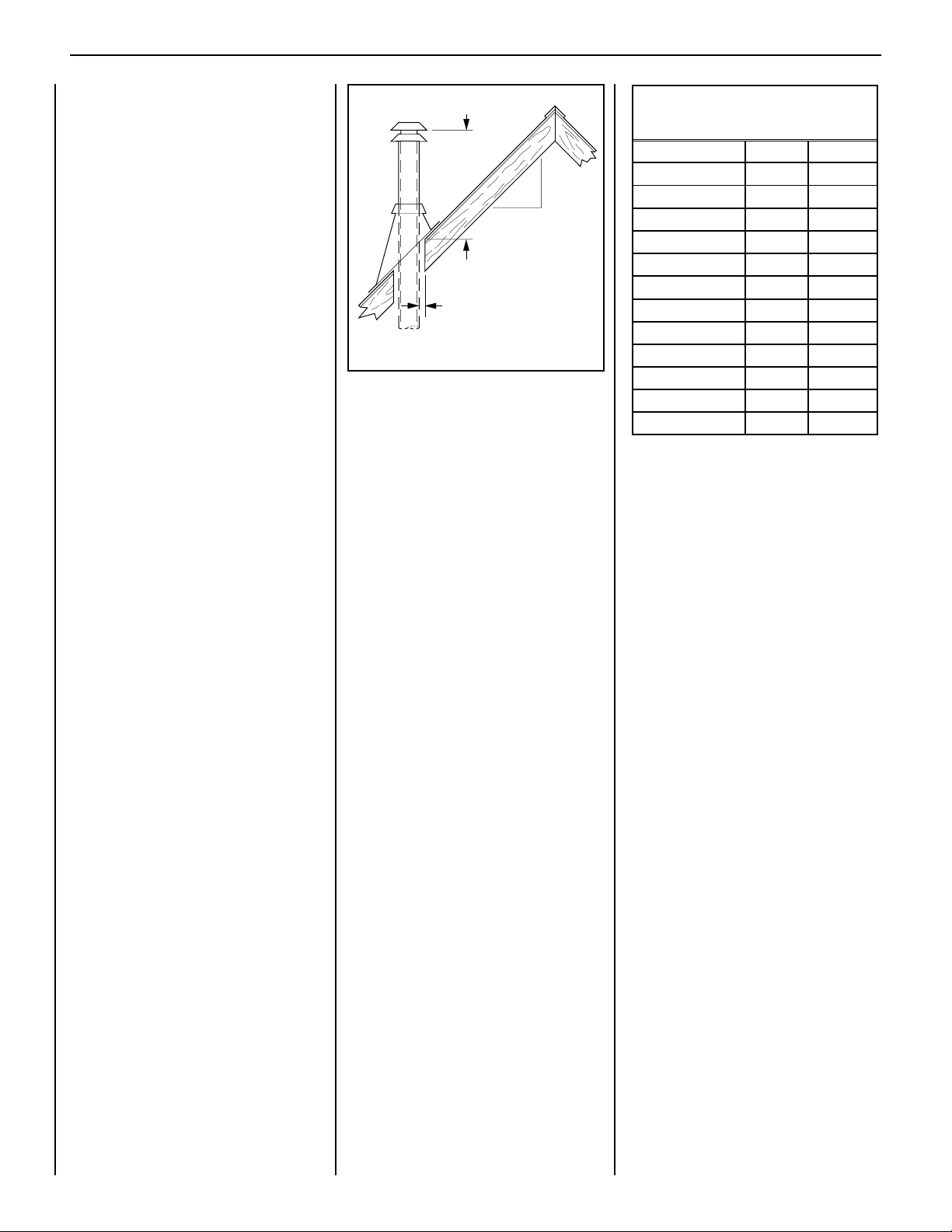
Gas Vent Rule
Gas vent caps are not permitted within 8 ft (2.4
m) of a vertical wall or similar obstruction. Gas
vent caps that are located 8 ft or more from a
portion of a building that extends at an angle
greater than 45° upward from the horizontal
may terminate in accordance with Figure 4,
provided that any discharge opening on
the cap is NEVER LESS THAN 2 ft (0.6 m)
horizontally from the roof surface (National
Fuel Gas Code ANSI Z223.1 (NFPA 54) “Gas
Vent Termination” section) (CAN/CGA B149.1).
Gas Vent Rule
Figure 4
X
12
Roof Pitch is X/12
Minimum Height from Roof to
Lowest Discharge Opening
1" (25 mm)
Minimum
Termination Heights For Vents
Above Flat Or Sloped Roofs
Ref. NFPA 54 / ANSI Z223.1
Roof Pitch * Feet * Meters
Flat to 6/12 1.0 0.3
6/12 to 7/12 1.25 0.38
7/12 to 8/12 1.5 0.46
8/12 to 9/12 2.0 0.61
9/12 to 10/12 2.5 0.76
10/12 to 11/12 3.25 0.99
11/12 to 12/12 4.0 1.22
12/12 to 14/12 5.0 1.52
14/12 to 16/12 6.0 1.83
16/12 to 18/12 7.0 2.13
18/12 to 20/12 7.5 2.29
20/12 to 21/12 8.0 2.44
Table 5
6
NOTE: DIAGRAMS & ILLUSTRATIONS ARE NOT TO SCALE.
Page 7
5 (127)
8-1/4
(209)
14
(356)
12 (305)
19
(483)
SUPERIOR® B-VENT GAS FIREPLACES • MODELS SLBV-35, SLBV-40 • INSTALLATION INSTRUCTIONS
MINIMUM CLEARANCES TO COMBUSTIBLES
Appliance and Vent Clearances
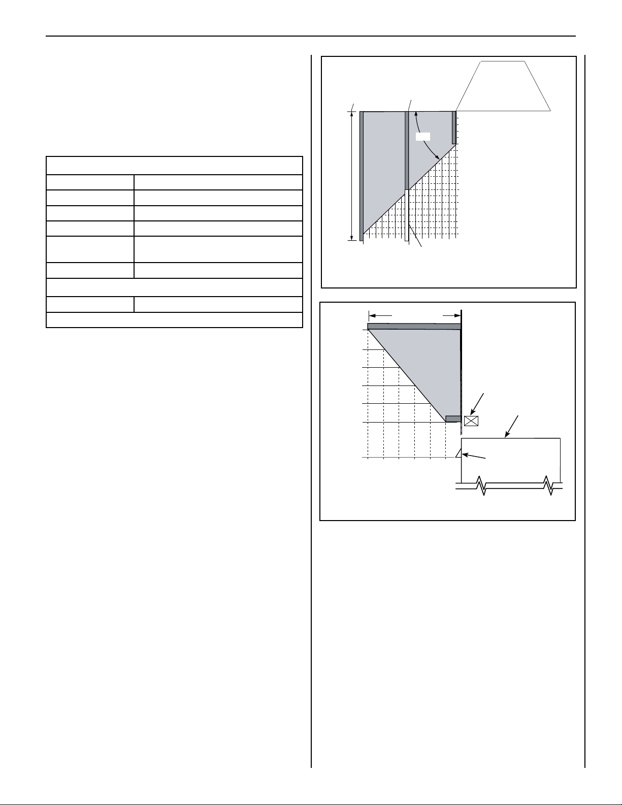
The appliance is approved with zero clearance to combustible materials
on all sides (as detailed in Table 6), with the following exception: When
the unit is installed with one side flush with a wall, the wall on the
other side of the unit must not extend beyond the front edge of the
unit (see Figure 5).
MINIMUM CLEARANCES - Inches (millimeters)
Back 0 (0) to Standoffs or Dimples
Sides 0 (0) to Standoffs or Dimples**
Top 3 in (76 mm)
Floor 0 (0)
From Bottom of Unit
to Ceiling
Vent 1 in (25.4 mm)
SERVICE CLEARANCES
Front 3 ft (0.9 m)
Table 6
**Note: See Step 1 on Page 8 for clearance requirements to the nailing
flange located at each side of the unit and any screw heads adjacent to it.
64 in (1626 mm)
At 14" minimum side
wall clearance, a
combustible wall can
project to any length.
At 8-1/4" side
wall clearance, a
combustible wall
can project 12".
o
45
Protected wall
shown in white
Top View of
Fireplace
Combustible Materials
Allowed In Shaded Area
“Safe Zone”
Combustible walls
shown in dark gray.
Combustible materials
may project beyond
one side of the
fireplace opening
as long as they are
kept within the shaded
areas illustrated here.
Inches (millimeters)
Figure 5 - Minimum Distance to Unprotected Side Wall
Mantel Depth
18 (457)
16 (406)
inches (millimeters)
Hearth Extension
A hearth extension is not required with this appliance. If a hearth extension
is used, do not block the lower control compartment door. Any hearth
extension used is for appearance only and does not have to conform to
standard hearth extension installation requirements.
Wall Finishes / Surrounds / Mantels
Note: Combustible wall finish materials and/or surround materials must
not be allowed to encroach the area defined by the appliance front face
(black sheet metal). Never allow combustible materials to be positioned
in front of or overlapping the appliance face (see Figure 5; also see
Figure 30 on Page 23).
Non-combustible materials, such as surrounds and other appliance trim,
may be installed on the appliance face with these exceptions: they must
not cover any portion of the removable glass panel.
Vertical installation clearances to combustible mantels vary according
to the depth of the mantel. See Figure 6. Mantels constructed of non-
combustible materials may be installed at any height above the appliance
opening; however, do not allow anything to hang below the replace hood.
Note: We recommend the use of high-temperature paint (rated 175°F or
higher) on the underside of the mantel.
14 (356)
12 (305)
10 (254)
8 (203)
12
(305)
10
(254)
(203)
6
8
(152)
(102)
2
4
(51)
Figure 6 - Minimum Mantel Clearances
Header
Top of
Appliance
Note - Hood shown
as positioned.
7
NOTE: DIAGRAMS & ILLUSTRATIONS ARE NOT TO SCALE.
Page 8
SUPERIOR® B-VENT GAS FIREPLACES • MODELS SLBV-35, SLBV-40 • INSTALLATION INSTRUCTIONS
Top
Standoff
Spacers*
Flush
Nailing
1/2"
Nailing
Flange
5/8"
Nailing
Flange
PRE-INSTALLATION STEPS
(Remove Glass Enclosure Panel)
The appliance is shipped with all gas controls
and components installed and pre-wired.
Note: Remove the glass enclosure panel
before installing the fireplace.
To remove the glass enclosure panel:
1. Remove the shipping carton, and then remove the shipping pad, exposing the front
glass panel.
2. Open the two latches securing the glass
panel (under the rebox oor).
3. Remove the glass panel by tilting it outward
at the bottom and lifting it up.
4. Set aside the glass enclosure panel in a
safe location to protect it from inadvertent
damage.
TYPICAL INSTALLATION
SEQUENCE
The typical sequence of installation is outlined
below, with page number references to the
related detailed instructions.
NOTE: Each installation is unique and may
result in variations to these steps.
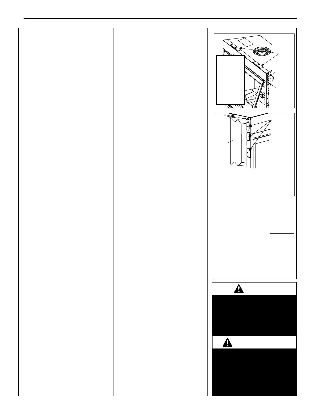
Step 1. (Pages 8–10) Construct the appliance
framing.
Position the appliance within the
framing and secure with nailing
brackets.
IMPORTANT! Bend up the appropri-
ate top standoff spacers for the
drywall/finish material thickness to
be used (see Figure 7). Bend up the
outer pair for 1/2" ma terials and the
inner pair for 5/8" materials.
Bend up the outer pair for 1/2" ma-
terials and the inner pair for 5/8"
materials.
Bend out the appropriate nailing
flanges for the drywall/finish material
to be used.
Nailing flanges are provided for flush
framing, 1/2 inch and 5/8 inch framing depths (see Figure 7).
Step 2. (Page 11) Route the gas supply line
to the appliance location.
Step 3. (Page 11) Install the vent system and
exterior termination.
Step 4. (Page 12) Install field wiring.
a. Millivolt Appliances: Install the
operating control switch (not factory
provided).
b. Electronic Appliances: Field wire
8
and install operating control switch.
Step 5. (Page 14) [OPTIONAL]: Install
outside supplemental combustion
air kit.
Step 6. (Page 15) Make connection to gas
supply.
Step 7. (Page 16) Verify appliance operation.
Step 8. (Page 17) Install the logs, decorative
volcanic stone, and glowing embers.
Step 9. (Page 20) Install the glass enclosure
panel.
Step 10. (Page 20) Adjust burner air shutter
to ensure proper flame appearance.
Step 11. (Page 22) Perform spillage test.
Step 12. (Page 23) Install hood.
Step 13. (Page 23) Complete finished interior
wall.
Step 14. (Page 24) Attach "Safety-in-
Operation" warnings.
DETAILED INSTALLATION STEPS
Step 1. Construct Appliance
Framing
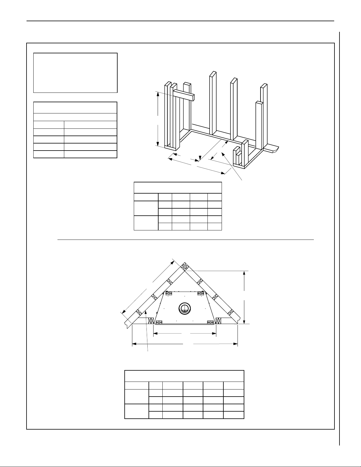
Frame the appliance as illustrated in Figures
8-1 and 8-2. All framing details must allow for
a minimum clearance to combustible framing
members as shown in Table 6, Page 7.
If the appliance is to be elevated above oor
level, a solid continuous platform must be
constructed below the appliance.
Headers may be in direct contact with the appli-
ance top standoff spacers when they are bent
up vertically, maintaining the 3" clearance to
the replace top, but must not be supported
by them or notched to fit around them. All
construction above the appliance must be
self-supporting. DO NOT use the appliance
for structural support.
Secure the fireplace to the side framing mem-
bers using the unit's nailing anges — one top
and bottom on each side of the replace front.
See Figure 7. Use 8d nails or equivalent.
NOTE: DIAGRAMS & ILLUSTRATIONS ARE NOT TO SCALE.
Header
Spacing
Top
Standoffs
*IMPORTANT!
Bend up the
Top Standoff
Spacers before
installation.
Use outer pair
for 1/2" materials
and inner pair
for 5/8" materials.
Side
Framing
(Left side front corner of fireplace shown.
NOTE: The nailing anges, combustible
members, and screw heads in areas directly
adjacent to the nailing anges are EXEMPT
from the 1/2” clearance to combustible
requirements for the rebox outer wrapper.
Combustible framing may be in direct contact
with the nailing anges and may be located
closer than 1/2” from screw heads and the
rebox wrapper in areas adjacent to the
nailing flanges.
Frame the opening to the exact dimensions
specified in the framing details in this manual.
Figure 7
~
Nailing flanges are
provided at all four
corners at 5/8", 1/2",
and flush settings.
Fireplace secured to framing
by nailing flanges
Right side requirements are the same.)
5/8”
Nailing
Flange
1/2”
Nailing
Flange
Fireplace
Nailing
Flanges
WARNING
Failure to position the parts in
accordance with these diagrams
or failure to use only parts specifically approved with this appliance
may result in property damage or
personal injury.
AVERTISSEMENT
Risque de dommages ou de
blessures si les pièces ne sont
pas installées conformément à
ces schémas et ou si des pièces
autres que celles spécifiquement
approuvées avec cet appareil sont
utilisées.
Page 9
SUPERIOR® B-VENT GAS FIREPLACES • MODELS SLBV-35, SLBV-40 • INSTALLATION INSTRUCTIONS
FIREPLACE AND FRAMING SPECIFICATIONS
NOTE: Diagrams, illustrations and
photographs are not to scale. Product
designs, materials, dimensions,
specifications, colors, and prices are
subject to change or discontinuance
without notice.
Input (BTU/HR) - MV & Electronic
Natural & Propane Gas
Models Input Rate (BTU/hr)
SLBV-35N 17,000
SLBV-35P 17,000
SLBV-40N 22,000
SLBV-40P 20,000
FIREPLACE FRAMING SPECIFICATIONS
Construct framing with 2x4 or larger lumber.
B
C
1/2
A
A
Framing Dimensions
Model No. A B C
SLBV-35
SLBV-40
in. 35-1/4 35-1/4 16
mm 895 895 406
in. 40-1/4 40-1/4 16
mm 1022 1022 406
“C” is the required framing depth dimension
when the finish material (drywall) thickness
is 1/2 in. (13mm).
Figure 8-1
CORNER FRAMING DIMENSIONS
F
D
E
Back wall of chase/enclosure
(including any finishing materials)
Corner Framing Dimensions
Model No. D E F G
SLBV-35
SLBV-40
in. 35-1/4 57-1/2 40-5/8 28-3/4
mm 895 1461 1032 730
in. 40-1/4 61-13/16 48-11/32 30-11/16
mm 1022 1554 1101 779
G
NOTE: DIAGRAMS & ILLUSTRATIONS ARE NOT TO SCALE.
9
Page 10
SUPERIOR® B-VENT GAS FIREPLACES • MODELS SLBV-35, SLBV-40 • INSTALLATION INSTRUCTIONS
M
Front View
H
L
K
J
Q
N
P
Top View
Flue Outlet for
B-Vent Connection:
35 Models = 4 in. (102 mm)
40 Models = 5 in. (127 mm)
9-1/4 in. (235 mm)
1/2 in.
(13 mm)
VERTICAL VENTING THROUGH CEILING
Frame Ceiling Opening: To locate the center of the vertical run, use a plumb line from the ceiling above the appliance.
M
N
P
1/2 in.
(13 mm)
Top View
Flue Outlet for
B-Vent Connection:
35 Models = 4 in. (102 mm)
40 Models = 5 in. (127 mm)
9-1/4 in. (235 mm)
H
L
K
J
Q
Front View
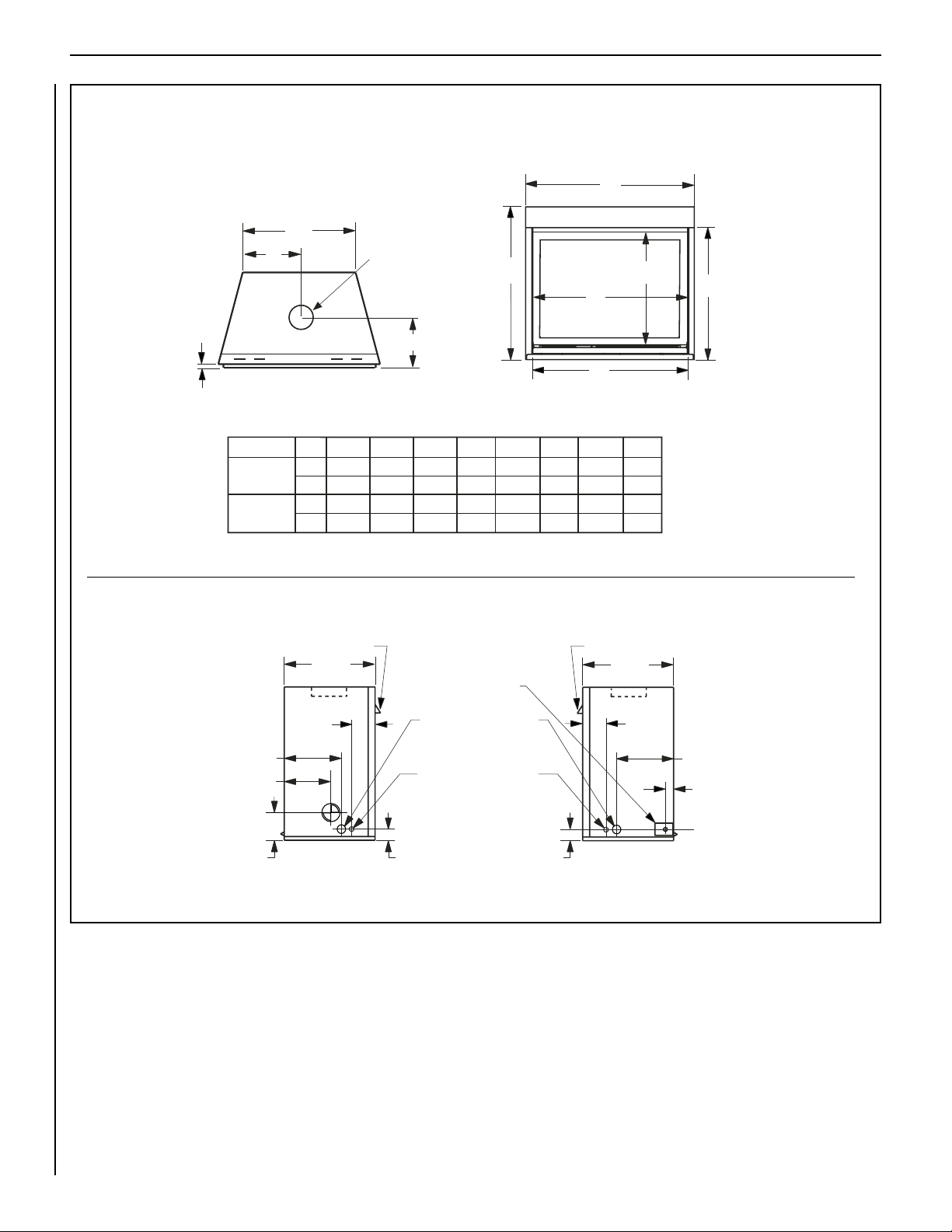
FIREPLACE SPECIFICATIONS
Figure 8-2
9-1/2 in. (241 mm)
7-1/8 in. (181 mm)
7-3/8 in. (187 mm)
Model No.
SLBV-35
SLBV-40
H J L M N P QK
32-1/4
in.
819
mm
in.
37-1/4
946
mm
Hood
16 in.
(406 mm)
5-7/8 in.
(149 mm)
Left Side View
28-1/8
23-1/4
59032813
714
28-1/4
33-1/8
841
71837940
ELECTRICAL INLET
2-3/4 in. x 2 in.
(70 mm x 51 mm)
COVER PLATE with
KNOCKOUT (Right Side)
GAS INLET KNOCKOUT*
*NOTE: It is recommended that gas
be stubbed in from LEFT side only.
Optional Electrical Inlet
Knockout requiring a
field-provided Junction
3 in. (76 mm)
Box (Either Side)
35-1/4
89525635
40-1/4
1022307621538138965
12-1/2
31733838
Hood
16 in.
(406 mm)
3 in. (76 mm)
Right Side View
5-7/8 in.
(149 mm)
9-1/2 in. (241 mm)
1-5/8 in. (42 mm)
10
NOTE: DIAGRAMS & ILLUSTRATIONS ARE NOT TO SCALE.
Page 11
SUPERIOR® B-VENT GAS FIREPLACES • MODELS SLBV-35, SLBV-40 • INSTALLATION INSTRUCTIONS
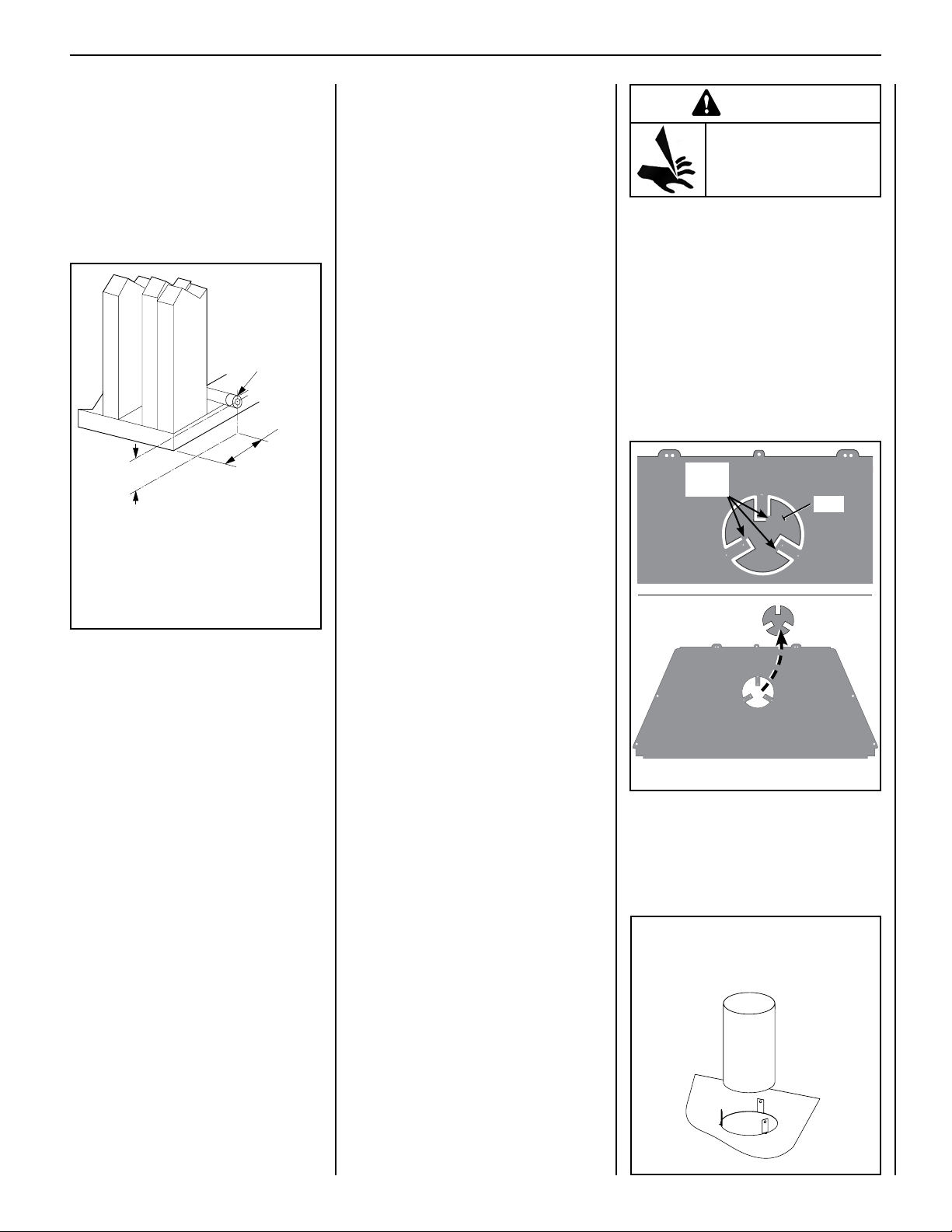
Step 2. Route the Gas Line
Route a 1/2" (13 mm) gas line to either side
of the appliance (left side routing is shown
in Figure 9 ). Gas lines must be routed, con-
structed, and made of materials that are in strict
accordance with local codes and regulations.
All appliances are factory-equipped with a flex-
ible gas line connector and 1/2-inch shutoff
valve. (See Step 6 on Page 15.)
Left Side Front
Corner of Fireplace
Framing
Pipe Coupling
(Recommended)
6-1/2"
(152 mm)
3"
(76 mm)
NOTE: Gas line can be routed to either
side. Reverse this illustration if routing
to right side.
Also see Figures 8-1 and 8-2.
Figure 9: Route Gas Line
Proper Sizing of Gas Line
Properly size and route the gas supply line
from the supply regulator to the area where the
appliance is to be installed per requirements
outlined in the National Fuel Gas Code, NFPA
54 - latest edition (USA) or CAN/CSA-B149.1 -
latest edition (Canada).
Never use galvanized or plastic pipe. Gas lines
must be routed, constructed and made of materials that are in strict accordance with local
codes and regulations.
IMPORTANT: It is critical that a licensed
installer perform this step strictly per
NFPA.
We recommend that a qualified, licensed
plumber or gas tter be hired to correctly size
and route the gas supply line to the appliance.
Installing a gas supply line from the fuel supply to
the appliance involves numerous considerations
of materials, protection, sizing, locations, controls, pressure, sediment, and more. Certainly no
one unfamiliar and unqualified should attempt
sizing or installing gas piping.
Note:
• All appliances are factory-equipped with
a exible gas line connector and 1/2 inch
shutoff valve (see Figure 17 on Page 15).
• See Massachusetts Requirements on Page
4 for additional requirements for installa-
tions in the state of Massachusetts in the
USA.
• The gas supply line should NOT be con-
nected to the appliance until Step 6 on Page
15).
• A pipe joint compound rated for gas should
be used on the threaded joints. Ensure that
propane-resistant compounds are used in
propane applications. Be very careful that
the pipe compound does not get inside the
pipe.
• It is recommended to install a sediment trap
in the supply line as close as possible to the
appliance. Appliances using propane should
have a sediment trap at the base of the tank.
• Check with local building ofcial for local
code requirements (e.g., whether below-
grade penetrations of the gas line are al-
lowed, etc.).
IMPORTANT: If propane is used, be aware that
if the tank size is too small (i.e., under 100 lbs
if this is the only gas appliance in the dwelling; ref. NPFA 58), there may be pressure loss
resulting in insufficient fuel delivery, which
can result in sooting, severe delayed ignition,
or other malfunctions. Any damage resulting
from an improper installation, such as this, is
not covered under the limited warranty.
Step 3. Install Venting System
and Exterior Termination
These instructions should be used as a
guideline and do not supercede local codes
in any way.
Install venting according to local codes, these
instructions, the current National Fuel Gas
Code in the USA (ANSI-Z223.1) or the current
standards in Canada (CAN/CSA-B149.1).
SLBV-35 and SLBV-40 series fireplaces must
be vertically vented using listed type-B,
double-walled vent pipe with the proper
diameter (as listed below) and a listed vent
termination.
Required Pipe Diameter
SLBV-35 series: Requires 4 in. (102 mm)
SLBV-40 series: Requires 5 in. (127 mm)
WARNING
Sharp Edges.
Watch Your Fingers!
WARNING: EDGES OF SHEET METAL ARE
SHARP! WEAR PROTECTIVE GLOVES AND USE
EXTREME CARE WHEN HANDLING.
Required tools:
•SheetMetal-resistantGloves
•TinSnips
1. Using tin snips, cut the three connecting
points securing the slug to the three tabs
in the flue collar (as shown in Figure 10a),
and remove the slug.
Carefully dispose of slug in an appropriate
container.
Cutting
points
Slug
Figure 10a
2. Connect the proper size Type B-vent system
to the replace ue collar by bending up the
three tabs and securing with three sheet
metal screws (No. 8 or larger) bend up tabs.
See Figure 10b. Then install the remainder
of the Type B-vent to the outside.
Type B-Vent
SLBV-35 models: 4 in. (102 mm)
SLBV-40 models: 5 in. (127 mm)
NOTE: DIAGRAMS & ILLUSTRATIONS ARE NOT TO SCALE.
Figure 10b
11
Page 12
Back View
Of Appliance
10 ft.
*12 ft. Min.
**15 ft. Min.
Minimum
Back View
Of Appliance
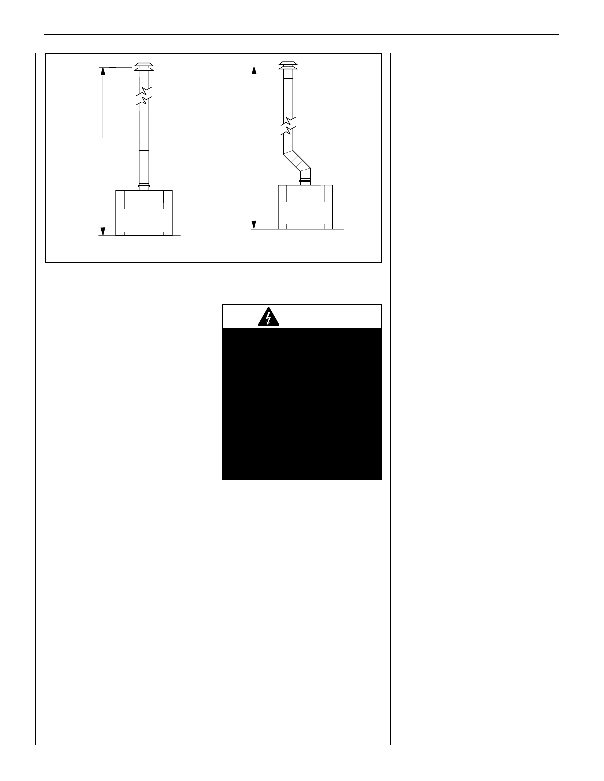
Figure 11
3. Refer to Figure 11. The following venting
congurations may be installed:
Vertical Installations
• Minimum overall height of the vent
system and appliance without an offset
must be 10 ft (2.54 m).
Offset Installations
• Offset up to 45 degrees from vertical:
Minimum overall height of the vent
system and appliance must be 12 ft
(3.66 m). The lower part of the offset
may start at the fireplace flue collar.
• Offset greater than 45 degrees and up
to 60 degrees from vertical: Minimum
overall height of the vent system and
appliance must be 15 ft (4.57 m). The
lower part of the offset may start at the
fireplace flue collar.
Maximum overall height of the vent system
and appliance should not exceed 40 ft
(12.19 m).
Install the B-vent system in accordance with
the vent manufacturer's instructions.
CAUTION: THIS APPLIANCE CANNOT BE
VENTED HORIZONTALLY.
Note: Refer to the vent manufacturers installation instructions for variations of venting
techniques. If common venting of several units
is contemplated, it should be discussed with an
architect and the local Building Department.
Do not place insulation materials within 1 in.
of the gas vent system.
12
SUPERIOR® B-VENT GAS FIREPLACES • MODELS SLBV-35, SLBV-40 • INSTALLATION INSTRUCTIONS
ON/OFF switch, the switch may be mounted
onto the Style View Door per instructions
provided in kit.
• The gas valve is set in place and pre-wired at
the factory on all models.
Refer to Section B (below) for millivolt appliances and Section C (below) for electronic
appliances.
Vertical
Installations
*12 ft. Min.
**15 ft. Min.
Offset
Installations
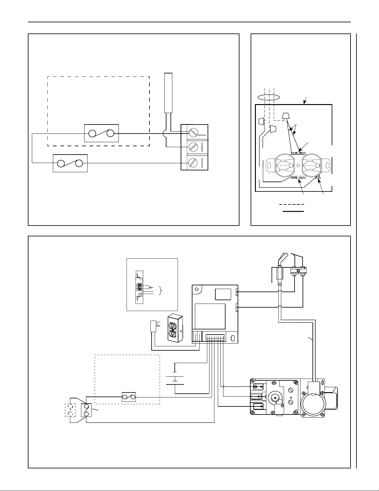
B. Millivolt Wiring (see Figure 12)
1. Read Section A, “All Models,” at left.
2. Wire the control switch within the millivolt
control circuit using the 15 feet of 2 conductor
Back View
Of Appliance
*with an offset up to 45 degrees
** with an offset greater than 45
degrees and up to 60 degrees
Step 4. Install Field Wiring
CAUTION
Ground supply lead must be connected to the wire attached to the
green ground screw located on the
outlet box. See
Figure 13. Failure to
do so will result in a potential safety
hazard. The appliance must be
electrically grounded in accordance
with local codes or, in the absence of
local codes, the National Electrical
Code, ANSI/NFPA 70-latest edition.
(In Canada, the current CSA C22-1
Canadian Electrical Code).
CAUTION: Label all wires prior to disconnection when servicing controls. Wiring errors
can cause improper and dangerous operation.
ATTENTION : Au moment de l'entretien
des commandes, étiquetez tous les fils
avant de les débrancher. Des erreurs
de cáblage peuvent entraîner un fonctionnement inadéquat et dangereux.
Verify proper operation after installing.
A. All Models
• An optional unit-mounted ON/OFF switch
may be installed in the lower control com-
partment.
• An optional wall-mounted ON/OFF switch or
optional ON/OFF remote control kit also may
be used.
• If a wall-mounted ON/OFF control switch is
used, mount it in a convenient location on a
wall near the fireplace.
• If an optional Style View Door is used in
conjunction with an optional unit-mounted
NOTE: DIAGRAMS & ILLUSTRATIONS ARE NOT TO SCALE.
wire supplied with the unit.
Note: The supplied 15 feet of 2 conductor
wire has one end of each conductor connected to the gas valve circuit and the other
end of each conductor placed loose inside
the bottom compartment.
CAUTION: Do Not connect the optional wall
switch to a 120V power supply.
C. Electronic Wiring (see Figure 13)
Note: The electronic appliance must be connected to the main power supply.
1. Read Section A, “All Models,” at left.
2. Route a 3-wire 120Vac 60Hz 1ph power
supply to the appliance junction box.
3. Remove the electrical inlet cover plate from
the side of the unit by removing the plate's
securing screws (see Figures 8-1 and 8-2
on Pages 9 and 10).
4. Remove the cover plate's knockout; then feed
the power supply wire through the knockout
opening and into the unit junction box.
5. Connect the black power supply wire to the
lower outlet's red pigtail lead and the white
power supply wire to the common terminal
of the outlet as shown in Figures 13 and 14.
6. Connect ground supply wire to pigtail lead
attached to outlet's green ground screw.
Note: Remote receiver should be located in the
wall, or if installed in the control compartment,
pulled all the way forward and completely to the
left or right against the corner posts. The glass
enclosure panel must be removed first to place
the receiver in the lower control compartment.
7. If using an optional control, wire it in the low
voltage circuit as shown in Figure 13.
Note: The supplied 15 feet of 2 conductor wire
has one end of each conductor connected
to the gas valve circuit and the other end
of each conductor placed loose inside the
bottom compartment.
8. After wiring is complete, replace cover plate.
Note: Do NOT install batteries in the battery
holder until needed (i.e., in the event of a
power outage or if operating the appliance
solely by batteries). The battery holder requires
two [2] "D" batteries.
Page 13
SUPERIOR® B-VENT GAS FIREPLACES • MODELS SLBV-35, SLBV-40 • INSTALLATION INSTRUCTIONS
H
I
L
O
W
P
I
L
O
T
O
N
ti
O
F
F
IN
OUT
TRANSFORMER 3V
BROWN
BROWN
BLACK
BATTERY BACK-UP
BLACK (SENSOR)
BLACK (IGNITER)
IGNITER MODULE
3V
RED
PILOT
IN
OUT
VENT
LO
HI
TH
TP
TH
TP
IN
ORANGE (THTP)
BLACK (TP)
GREEN (TH)
HIGH LIMIT SWITCH
Pilot Burner
Pilot Tube
Assembly
Schematic Representation Only
Electronic Gas Control Valve - DEXEN
B-Vent appliances only - High limit
switch must be factory installed as
shown. If wires to this switch are
replaced, wires must be Type AWM
200°C - 18 gage wire ONLY.
CONTROL
SWITCH *
UNIT MOUNTED
ON/OFF SWITCH,
IF SUPPLIED
Junction Box
J-Box Wiring
BK
W
G
CAV 021
* Control Switches: Wall On/Off
Switch, Unit Mounted On/Off Switch
or Remote Control Switch.
NOTES:
1. If any of the original wire as supplied
must be replaced, use Type AWM
105°C - 18 gage wire ONLY.
2. 120 VAC, 60 Hz - Less than 3 Amps.
CAUTION: label all wires prior to
disconnection when servicing controls.
Wiring errors can cause improper and
dangerous operation. Verify proper
operation after servicing.
MILLIVOLT WIRING DIAGRAM
CAUTION: WHEN SERVICING CONTROLS, LABEL ALL WIRES PRIOR TO DISCONNECTION.
WIRING ERRORS CAN CAUSE IMPROPER AND DANGEROUS OPERATION.
VERIFY PROPER OPERATION AFTER SERVICING.
Figure 12
B-VENT APPLIANCES ONLY: The High Limit
Switch must be factory installed in series,
as shown. If wires to this switch must be
replaced, use Type AWM 200°C - 18 gage
wire ONLY.
High Limit Switch
Control Switch*
If any of the original wire must be replaced,
use Type AWM 105º C - 18 gage wire ONLY.
_________
*Control switch options: ON/OFF wall switch, unit-mountable
ON/OFF switch, or ON/OFF remote control system (see "Accessory
Components" in the Care and Operation Instructions).
Thermopile
Gas Control
Valve Terminals
J-BOX/RECEPTACLE WIRING
J-BOX / RECEPTACLE
120V, 60HZ, 1PH
120V, 60HZ, 1PH
Neutral - White
Ground - Green
120 VAC - Black
WIRING
Junction Box
T
TP HTP
Black
Tab Intact
Hot Side of
TH
White
Green
Receptacle
Neutral Side
of Receptacle
Tab Intact
Field Wired
Green Ground
Screw
Factory Wired
Figure 14
Figure 13
ELECTRONIC IGNITION WIRING DIAGRAM
NOTE: DIAGRAMS & ILLUSTRATIONS ARE NOT TO SCALE.
See Figure 14 for detailed drawing of junction box / receptacle wiring.
_________
*Control switch options: ON/OFF wall switch, unit-mountable
ON/OFF switch, or ON/OFF remote control system (see "Accessory
Components" in the Care and Operation Instructions).
13
Page 14
SUPERIOR® B-VENT GAS FIREPLACES • MODELS SLBV-35, SLBV-40 • INSTALLATION INSTRUCTIONS
Step 5. [OPTIONAL] Install Outside
Combustion Air Kit
An optional outside combustion air kit (model
FOAK-4, FOAK-4LD, or DK-4) may be used
with these appliances (see "Installation Accessories," at right).
Refer to the instructions included with the
air kits for specific installation information.
If used, the outside air kit must be installed
before the replace is framed and enclosed in
the finished wall.
Outside air drawn into the fireplace supplies
supplemental combustion air to the re. Only
one outside air duct is necessary, if installed.
If additional length of duct is necessary, purchase locally available U.L. Class 0 or Class 1
metallic ducting. The duct may extend up to 50'
(15.24 m) in one continuous piece.
Note: When installing the air duct vertically, do
NOT terminate the duct closer than 3' below
the chimney top.
Outside supplemental combustion air ducting
may be run upward or vertically through framing and ceiling joists, with the hood installed
through an outside wall and 3' (1 m) below the
termination. Ducting may also be run down-
ward through floor joists and under the home
to a ventilated crawlspace not considered part
of the living area of the home.
Note: NEVER terminate an outside supplemental combustion air kit in attic space
under any circumstances.
Failure to do so may result in extensive and
costly rework. Before the operation of the vent
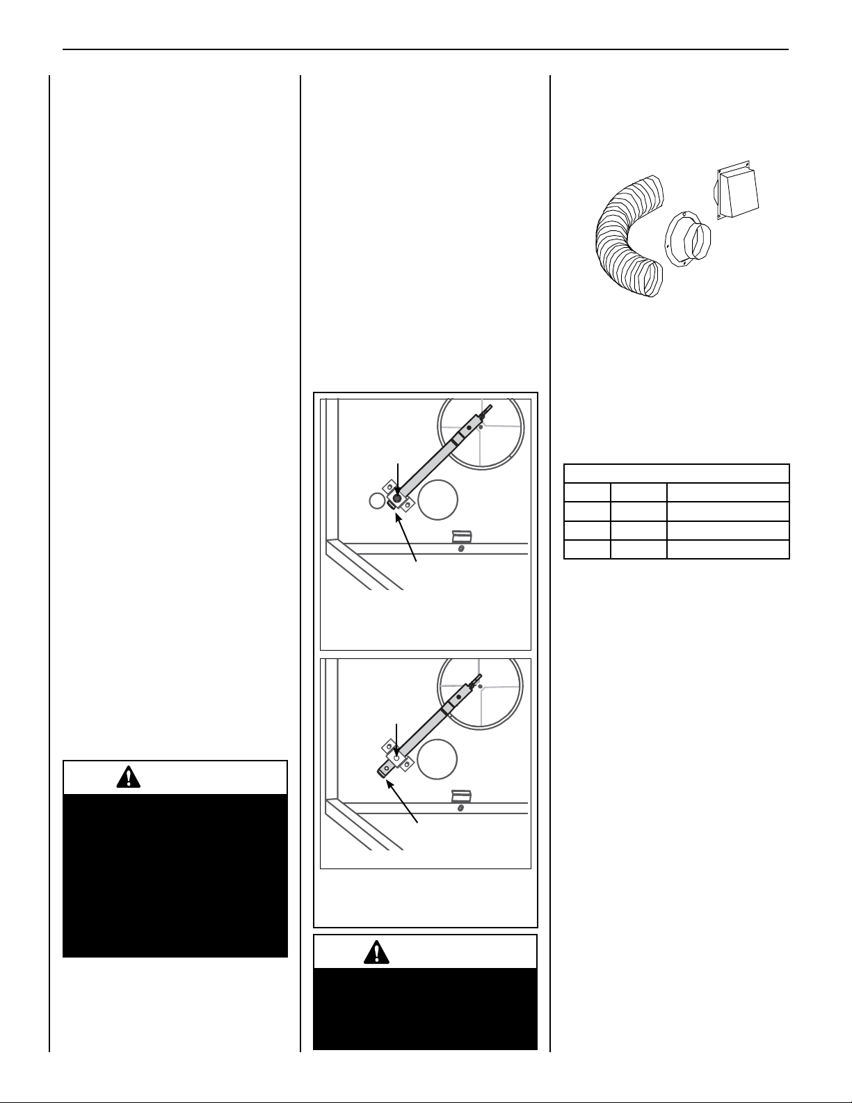
system can be tested, the lever securing screw
must be removed. See Figure 15.
The hand-operated outside air control lever
is located on the left side of the lower control
compartment opening. See Figure 15.
To open the outside air shutter, open the bottom
control access panel, reach into the control compartment, and pull the outside air control lever
all the way out. The outside air shutter should
be fully open when the replace is in use and
completely closed when the replace is not being
used. Closing it when not in use will help limit the
amount of outside cold air entering the dwelling.
Operate the actuator through several cycles
including the closed position. Ensuring proper
operation and freedom of movement. Return
the actuator arm to the closed position.
Securing
Screw
Installed
Outside Air Control
Lever pushed UP
(Air Shutter CLOSED)
IMPORTANT: Do NOT move Air Control
Lever if securing screw is installed
(or if not sure it was removed).
INSTALLATION ACCESSORIES
The following accessory items are available for
use in the installation of this appliance.
Outside Combustion Air Kits
Models FOAK-4 and FOAK-4LD
Outside combustion air kits are available with
duct (FOAK-4) and without duct (FOAK-4LD)
for use if supplemental outside combustion
air is required or desired. If model FOAK-4LD
is used, it must be used in conjunction with
locally purchased, non-combustible Class 1 or
Class 0 exible duct.
Outside Combustion Air Kits
Cat. No. Model No. Description
81L87 FOAK-4 Combustion Air Kit (w/duct)
81L88 FOAK-4LD Combustion Air Kit (w/o duct)
H5377 DK-4 Single 4" Duct Kit
After completing installation of the optional
outside air vent system the outside air control
lever must be put in service and tested to ensure proper operation before completing any
enclosure around the rebox.
CAUTION
Never locate inlet where it can be
blocked by shrubs, snow drifts,
etc. Never locate inlet in garage
or any area where there is another
fuel burning appliance or products
emitting combustible gases such
as paint, gasoline, etc. In cold
climates, it is recommended the
outside air duct be insulated.
14
Securing
Screw
Removed
Outside Air Control
Lever pulled DOWN
(Air Shutter OPEN)
Left Side of
Lower Control Compartment
Figure 15
WARNING
Do not operate the shutoff lever
unless a complete outside combustion air system has been
installed with your appliance.
NOTE: DIAGRAMS & ILLUSTRATIONS ARE NOT TO SCALE.
Page 15
SUPERIOR® B-VENT GAS FIREPLACES • MODELS SLBV-35, SLBV-40 • INSTALLATION INSTRUCTIONS
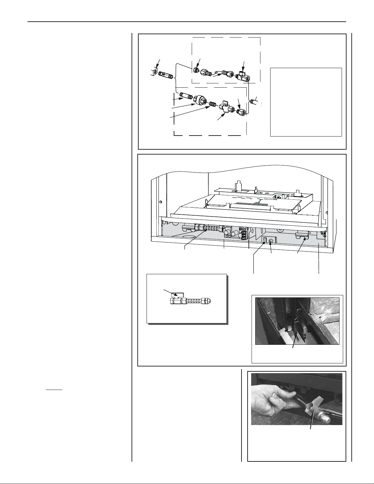
Gas
Valve
3/8" NPT x
Flare Fitting
3/8" Flex Tubing
3/8" Nipple
3/8" Union
3/8" Close
Nipple
3/8" Shut-off Valve
1/2" x 3/8"
Reducer
Gas
Stub
1/2" x 3/8" Flare
Shut-off Valve
Gas Solid Line Connector
Gas Flex Line Connector
*Sediment
Trap
3"
Mi
n
Note: Millivolt system shown. Electronic system controls are similarly located.
Step 6. Connect the Gas Line
All codes require a shut-off valve mounted in
the supply line. The orientation of the shutoff valve should face the front. Figure 16
illustrates two methods for connecting the gas
supply. A sediment trap is recommended in the
gas piping within the home to prevent moisture
and debris in the line from damaging the valve.
The ex-line method is acceptable in the U.S.A.
where local codes permit, however, Canadian
requirements vary depending on locality. Instal-
lation must be in compliance with local codes.
These appliances are equipped with a gas flexline for use in connecting the unit to the gas line.
See Figure 16 for flex-line description. The
ex-line is rated for both natural and propane
gas. A manual shut off valve is also provided
with the flex-line.
The gas control valve is located in the lower
control compartment.
Access the valve compartment by removing the
lower control compartment panel (see Figure
17) by lifting and pulling the panel forward.
The panel is mounted on supporting tabs at
the extreme right and left hand sides. Engage
the tabs into the reliefs in the panel.
The millivolt and electronic control valve has a
3/8" (10 mm) NPT thread inlet port.
Secure all joints tightly using appropriate
tools and sealing compounds (ensure propane
resistant compounds are used in propane applications). It is recommended to seal around
the gas line to prevent cold air leakage.
Gas line connection may be performed largely
outside of the confines of the control compart-
ment and without having to enter the rebox
behind the glass. Proceed as follows:
Acquire the shut-off valve and gas flex-line and
pull the assembly forward out of the compartment. Separate the shut-off valve from the gas
ex-line. Determine the length of pipe needed
to route the gas line from the last fitting (shown
in Figure 9) to a point within the control compartment that will allow the shut-off valve to
be easily attached by hand to the gas ex-line.
Using pipe-dressing materials appropriate for
the gas type, securely afx the shut-off valve
to this determined pipe length at a convenient
location outside of the appliance lower control
compartment.
Refer to Figure 18. Insert the last length of gas
pipe with its attached shut-off valve into the
lower control compartment, and pass it through
the gas line access hole on the left side of the
appliance outer wrapper.
Using appropriate materials for the gas type,
thread the last length of pipe into the end of
the gas vent run and tighten in place using a
pipe wrench external to the appliance between
the appliance outer wrapper and the framing.
Important: Turn the last piece of gas pipe in
the last fitting until the shut-off valve is positioned in a way that allows the shut-off valve
handle to be accessed in the lower control
compartment, easily operated throughout its
full range of motion.
Bring the ex-line to the shutoff valve by hand
and align the flare fittings. Tighten the fittings
by hand, and then use wrench to tighten completely, 1/4-turn at a time.
Figure 16: Gas Connection
Gas Flex Line
(Gas Shut-Off Valve is behind
door latch; see DETAIL, below)
DETAIL:
Gas Shut-Off Valve
in ON position (gas line OPEN)
To shut OFF gas: Turn valve handle
perpendicular (cross-wise) to gas line.
Figure 17
NOTE: DIAGRAMS & ILLUSTRATIONS ARE NOT TO SCALE.
Gas Control
{
Valve
Optional
Unit-Mounted
ON/OFF Switch
Note: The gas supply
line must be installed in
accordance with building
codes by a qualied installer
approved and/or licensed
as required by the locality.
In the Commonwealth of
Massachusetts, installation
must be performed by a
licensed plumber or gas tter.
~
Piezo
(Millivolt
units only)
DETAIL: Lower Control Compartment
Length of pipe with attached
Gas Shut-Off Valve in OFF position
Figure 18
Spring
Door Latch
(one of two)
Lower Control
Compartment
Door Tab
(gas line CLOSED)
(shaded area)
15
Page 16
SUPERIOR® B-VENT GAS FIREPLACES • MODELS SLBV-35, SLBV-40 • INSTALLATION INSTRUCTIONS
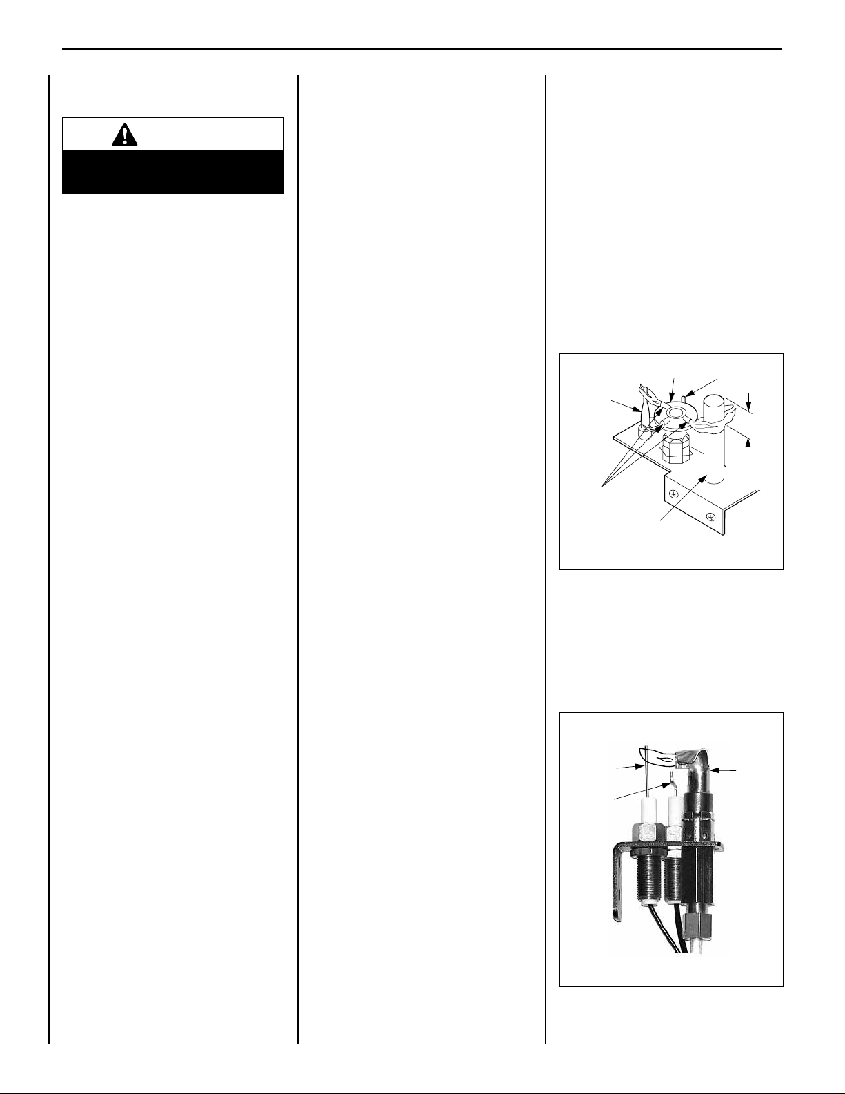
MILLIVOLT
Thermocouple
Hood Igniter Rod
3/8" Min
(9 mm)
Thermopile
Pilot
Nozzels
Test All Connections for Gas Leaks
(Factory and Field)
WARNING
Never use an open flame to
check for leaks.
Turn on gas supply and test for gas leaks, using a gas leak test solution (also referred to as
bubble leak solution).
Note: Using a soapy water solution is an
effective leak test solution but it is not recommended, because the soap residue that is left
on the pipes/fittings can result in corrosion
over time.
A. Light the appliance (refer to the lighting
instructions label in the control compartment
or in the Care and Operation Instructions
manual).
B. Brush all joints and connections with the gas
leak test solution to check for leaks. If bubbles
are formed, or gas odor is detected, turn the
gas control knob (off/pilot/on) to the “OFF”
position. Either tighten or refasten the leaking
connection, then retest as described above.
C. When the gas lines are tested and leak free,
be sure to rinse off the leak testing solution.
Step 7. Verify Appliance
Operation
Turn on burner then observe the individual
tongues of ame on the burner. Make sure
all ports are open and producing flame evenly
across the burner. If any ports are blocked, or
partially blocked, clean out the ports.
With gas line installed run initial system check-
out before closing up the front of the unit. Follow
the pilot lighting instructions provided in the
Care and Operation Instructions manual. For
piezo igniter location, see Figure 17 (millivolt
appliances only).
Note: Lighting Instructions are also found on
the literature tag tied to the gas piping next
to the gas valve. To access the tag, open the
lower control compartment door by pulling
the panel forward (see Figures 17 and 25).
When rst lighting the appliance, it will take a few
minutes for the line to purge itself of air. Once
purging is complete, the pilot and burner will
light and operate as indicated in the instruction
manual. Subsequent lighting of the appliance will
not require such purging. Inspect the pilot flame
(remove logs, if necessary, handling carefully).
Millivolt Appliance Checkout
The pilot ame should be steady, not lifting
or oating. Flame should be blue in color with
traces of orange at the outer edge.
The top 3/8" (10 mm) at the pilot generator
(thermopile) and the top 1/8" minimum (tip)
of the quick drop out thermocouple should be
engulfed in the pilot flame.
The ame should project 1" (25 mm) beyond
the hood at all three ports (see Figure 19).
Replace logs if removed for pilot inspection.
To light the burner; turn “ON” the remote wall
switch and rotate the gas valve control knob
counterclockwise to the “ON” position (“ON”
will be at the top side of the valve).
Figure 19
Electronic Appliance Checkout
To light the burner, turn ‘ON’ the unit mounted
On/Off switch or the optional remote wall switch.
Ensure the igniter lights the pilot. The pilot
flame should engulf the flame rod as shown
in Figure 20.
ELECTRONIC
Sensor
Igniter
Figure 20
Pilot
Hood
16
NOTE: DIAGRAMS & ILLUSTRATIONS ARE NOT TO SCALE.
Page 17
SUPERIOR® B-VENT GAS FIREPLACES • MODELS SLBV-35, SLBV-40 • INSTALLATION INSTRUCTIONS
Step 8. Install Volcanic Stone,
Glowing Embers (Rockwool),
and Logs
NOTE: Turn OFF all electricity to the fireplace before installing volcanic stone,
glowing embers, or logs.
1. Remove the front glass enclosure panel
(see “Removal and Installation of Glass
Enclosure Panel,” on previous page).
2. Install ceramic brickaded panel liners.
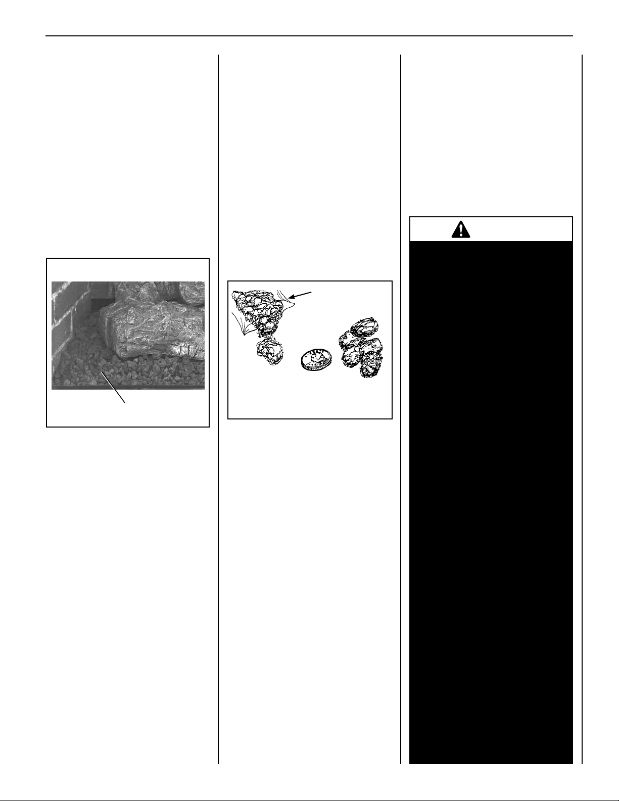
3. Install decorative volcanic stone. Refer to
Figure 21. Sprinkle the decorative volcanic
stone in a pleasing pattern directly on the
rebox bottom, along the slope and to the
back, at the right and left sides of the burner.
Volcanic Stone
Place Volcanic
Stone As Shown
Figure 21
4. Place the glowing ember material
(rockwool).
Note: The bag of Glowing Embers
contains enough rockwool for several
applications; therefore, do not use the
entire bag at one time. For best glowing effect, replace the ember material
annually.
Refer to Figure 22. Separate the glowing
ember material into pieces about the size
of a quarter. Keep the pieces uffed up, not
matted. Distribute the pieces over the surface of the burner, as shown in Figures 23
and 24. Do not use more than is necessary.
Position the embers on the small holes of
the ember bed area.
Note: Make sure the glowing ember
material does NOT cover the main
burner slots.
Bag of Glowing
Embers (Rockwool)
Separate into individual
“Quarter-sized” pieces.
Figure 22
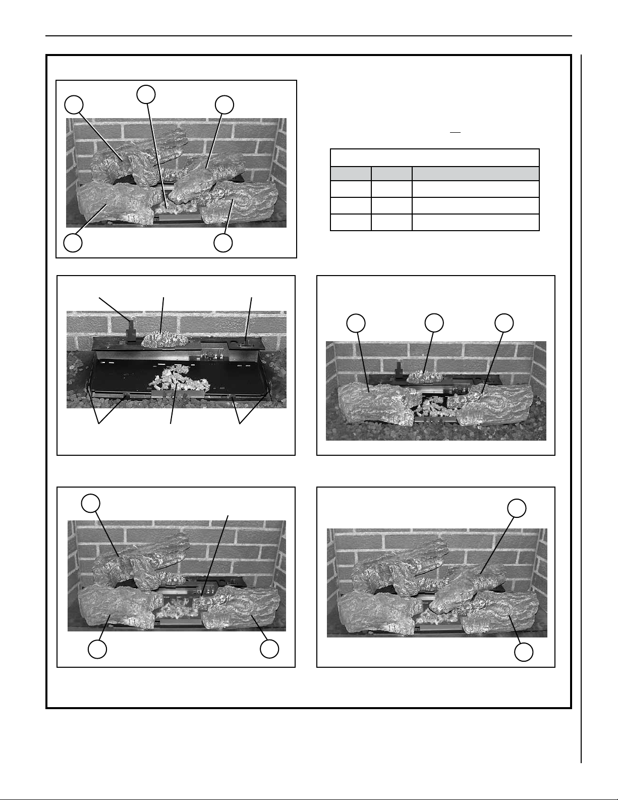
5. Install the Logs.
The logs have locating notches or slots to
help ensure that they are properly positioned.
The top logs that rest on lower logs, do so
over notches, indents or nubs. Proper log
placement is critical to prevent sooting.
Logs should be placed in the gaps between
the ame peaks and should be positioned so
they do not impinge the flames. Follow the
log placement instructions exactly.
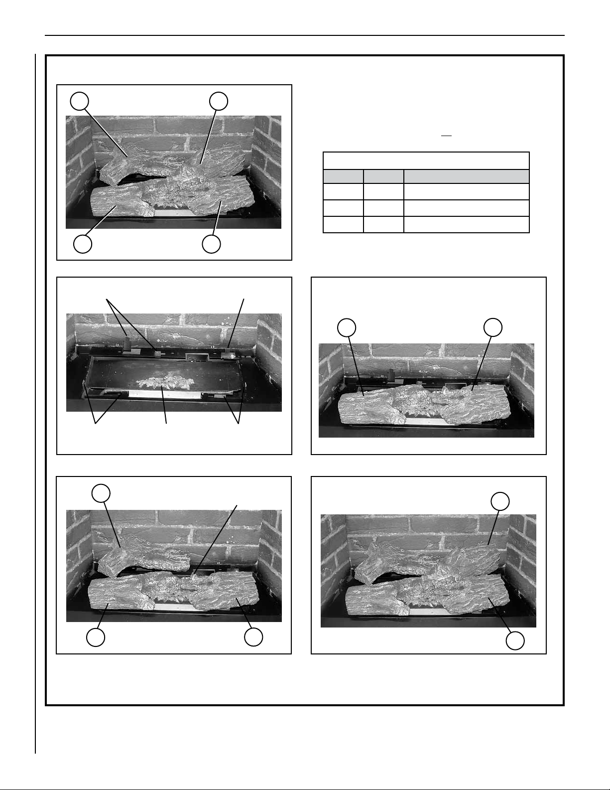
SLBV-35: Install logs as shown in Figure 23.
SLBV-40: Install logs as shown in Figure 24.
WARNING
• DO NOT attempt to install
the logs until the appliance
installation has been
completed, the gas line
connected and tested for leaks
and the initial burner operation
has been checked out.
• The size and position of the log
set was engineered to give the
appliance a safe, reliable and
attractive flame pattern. Any
attempt to use a different log
set in the fireplace will void
the warranty and will result
in incomplete combustion,
sooting, and poor flame
quality.
NOTE: DIAGRAMS & ILLUSTRATIONS ARE NOT TO SCALE.
• Logs get very hot and will
remain hot up to one hour
after gas supply is turned off.
Handle only when logs are
cool. Turn off all electricity
to the appliance before you
install grate, volcanic stone,
embers, and logs.
• This appliance is not designed
to burn wood. Any attempt to
do so could cause irreparable
damage to the appliance and
prove hazardous to your safety.
• If logs are not installed
according to the log
installation instructions, flame
impingement and improper
combustion could occur and
result in soot and/or excessive
production of carbon monoxide
(CO), a colorless, odorless,
toxic gas.
17
Page 18
SUPERIOR® B-VENT GAS FIREPLACES • MODELS SLBV-35, SLBV-40 • INSTALLATION INSTRUCTIONS
SLBV-35 LOG PLACEMENT INSTRUCTIONS
Left Rear Log Right Rear Log
3
Left Front Log
1
Left Rear Brackets
4
Right Front Log
2
Right Rear Bracket
Note:
•Ceramic fiber logs are FRAGILE! Handle carefully to prevent breakage.
•Install volcanic stone and glowing embers BEFORE installing logs.
•To prevent sooting, make sure logs do not cover any burner openings.
SLBV Firebox Accessories/Parts
Cat. No. Model No. Description
H7244 — SLBV-35 Log Set Assembly
88L53 FGE Bag of Glowing Embers (Rockwool)
80L42 FDVS Bag of Decorative Volcanic Stone
Align hole at the bottom of left front log (1) over the left front
brackets and the right front log over the right front brackets.
1
2
Figure 23
Glowing Embers
(Do not place Glowing Embers over burner slots.)
Step 1
Position on the left
3
rear log brackets
Right Front BracketsLeft Front Brackets
Right Front Log "Nub"
1
Step 3
Step 2
Align the hole at the bottom of log (4)
over the “nub” of log (2) as shown.
2
Step 4
4
2
18
NOTE: DIAGRAMS & ILLUSTRATIONS ARE NOT TO SCALE.
Page 19
SUPERIOR® B-VENT GAS FIREPLACES • MODELS SLBV-35, SLBV-40 • INSTALLATION INSTRUCTIONS
SLBV-40 LOG PLACEMENT INSTRUCTIONS
Ember Chunk
4
Left Rear Log Right Rear Log
Left Front Log Right Front Log
2
Left Rear
Bracket
1
Place Ember Chunk Here
5
3
Right Rear Bracket
Note:
•Ceramic fiber logs are FRAGILE! Handle carefully to prevent breakage.
•Install volcanic stone and glowing embers BEFORE installing logs.
•To prevent sooting, make sure logs do not cover any burner openings.
SLBV Firebox Accessories/Parts
Cat. No. Model No. Description
H7245 — SLBV-40 Log Set Assembly
88L53 FGE Bag of Glowing Embers (Rockwool)
80L42 FDVS Bag of Decorative Volcanic Stone
Align hole at the bottom of left front log (2) over the left front
brackets and the right front log over the right front brackets.
2
1
3
Figure 24
Glowing Embers
(Do not place Glowing Embers over burner slots.)
Step 1
Position on the left
4
rear log bracket
Right Front BracketsLeft Front Brackets
Right Front Log "Nub"
2
Step 3
Step 2
Align the hole at the bottom of log (5)
over the "Nub" of log (3) as shown.
3
Step 4
5
3
NOTE: DIAGRAMS & ILLUSTRATIONS ARE NOT TO SCALE.
19
Page 20
SUPERIOR® B-VENT GAS FIREPLACES • MODELS SLBV-35, SLBV-40 • INSTALLATION INSTRUCTIONS
Header
Spacing
Top
Standoffs
1/2”
Nailing
Flange
5/8”
Nailing
Flange
Top
Standoff
Spacers*
Flush
Nailing
1/2"
Nailing
Flange
5/8"
Nailing
Flange
Step 9. Install the Glass Enclosure
Panel
WARNING
• Do not attempt to substitute the
materials used on these doors, or
replace cracked or broken glass.
•Handlethisglasswithextreme
care! Glass is susceptible to
damage – Do not scratch or
handle roughly while reinstalling
the glass door frame.
•Theglassdoor(s)ofthisappliance must only be replaced as a
complete unit as provided by the
manufacturer. Do not attempt
to replace broken, cracked or
chipped glass separately.
• Do not attempt to touch the front
enclosure glass with your hands
while the fireplace is in use.
WARNING
Do not operate appliance with
the glass front removed, cracked
or broken.
AVERTISSEMENT
Ne pas utiliser l'appareil si le
panneau frontal en verre n'est
pas en place, est craqué ou
brisé.
Only doors certified with the appliance
shall be used.
Seules des portes certifiées pour cet
appareil doivent être utilisées.
CAUTION: DO NOT abuse glass enclosure
panel by striking or slamming shut.
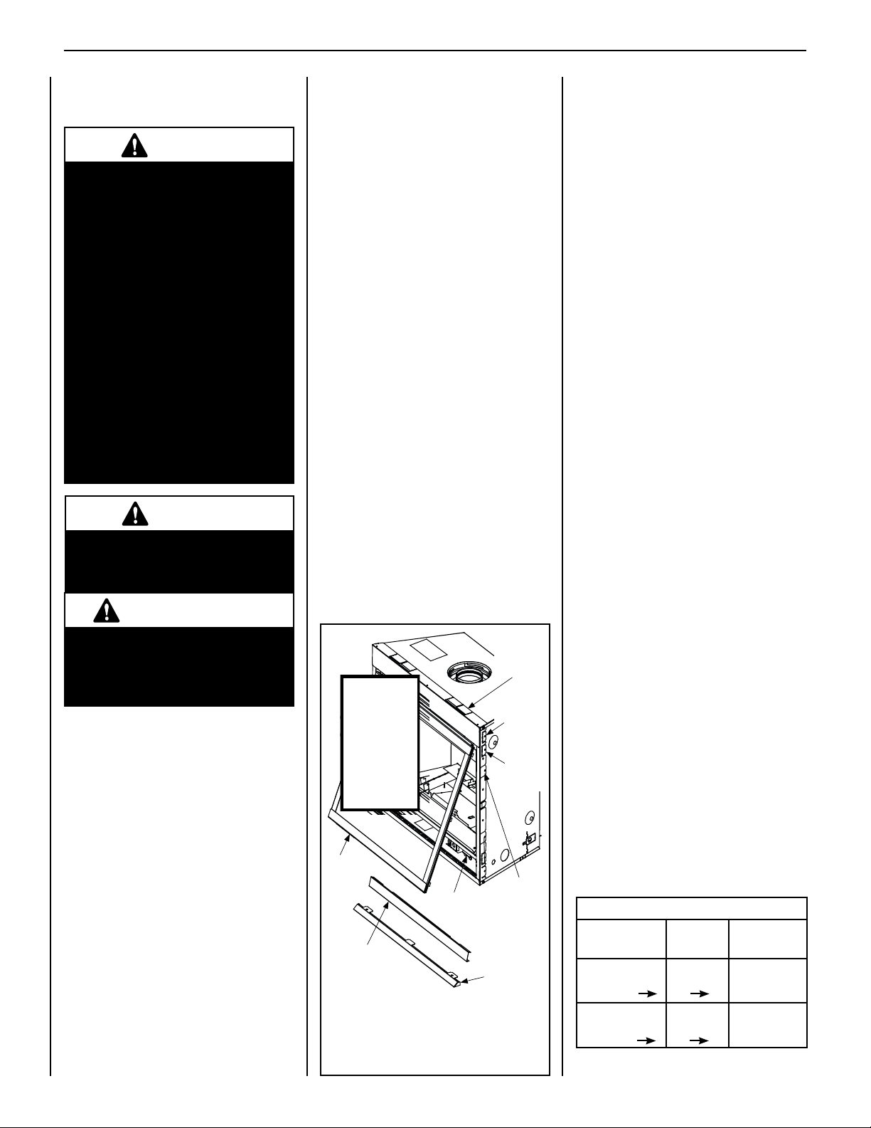
Installing the Glass Enclosure Panel
1. Refer to Figure 25. Position the glass enclo-
sure panel in front of the rebox opening,
with the bottom of the enclosure panel held
away from the fireplace. Hook the top flange
of the enclosure panel frame over the top of
the rebox frame.
2. Gently move the bottom of the enclosure
panel frame toward the replace, ensuring
that the gasket seats evenly. Fasten the
two latches under the rebox oor to the
vee-flange on the enclosure panel. Close
20
both latches securely.
3. Install the hood. Note the location of the
three clips inside the top air channel above
the glass enclosure panel. The clips are
equally spaced on the top surface of the air
channel opening. If needed, use a screwdriver to open the clips slightly. Engage
the back edge of the hood into the clips to
secure.
Removing the Glass Enclosure Panel
1. Refer to Figure 25. To access the spring
latches securing the front glass enclosure
panel, open the lower control compartment
door by lifting and pulling the bottom panel
forward.
2. Pull the spring latches forward and down to
release them from the lower door channel.
3. Pull the bottom of the glass enclosure panel
out a few inches, and grasp it on the right
and left sides. Gently lift to release the panel
from its upper channel, and then pull the
enclosure panel forward to remove it.
4. Visually inspect the gasket on the backside
of the enclosure panel frame. The gasket
surface must be clean, free of irregularities,
and firmly seated.
This appliance is designed to operate only
when the glass enclosure panel is installed.
Do NOT remove the glass enclosure panel unless necessary (e.g., to gain access to components within the rebox or to clean the glass).
Header
Spacing
Top
Standoffs
*IMPORTANT!
Bend up the
Top Standoff
Spacers before
installation.
Use outer pair
for 1/2" materials
and inner pair
for 5/8" materials.
Glass
Door
Glass Door
Spring Latch
Control
Compartment
Panel
Note: When installing the glass enclosure
panel, make sure spacing on both sides is
even and equal.
Figure 25
NOTE: DIAGRAMS & ILLUSTRATIONS ARE NOT TO SCALE.
Hood
5/8”
Nailing
Flange
1/2”
Nailing
Flange
Flush
Nailing
Flange
Step 10. Burner Air Shutter
Adjustments
(QUALIFIED TECHNICIANS ONLY)
Flame Appearance and Sooting
Proper flame appearance is a flame which is
blue at the base and becomes yellowish-orange
in the body of the ame. When the appliance
is rst lit, the entire ame may be blue and will
gradually turn yellowish-orange during the first
15 minutes of operation. After 15 minutes of
operation, if the ame is blue, or if the ame is
orange with evidence of sooting (black tip), the
air shutter opening may need to be adjusted.
If the air shutter opening is closed too far, sooting
may develop. Sooting is indicated by black puffs
developing at the tips of very long orange flames.
Sooting results in black deposits forming on the
logs, appliance inside surfaces and on exterior
surfaces adjacent to the vent termination.
Sooting is caused by incomplete combustion
in the ames and lack of combustion air enter-
ing the air shutter opening. To achieve a warm
yellowish-orange ame with an orange body
that does not soot, the shutter opening must be
adjusted between these two extremes.
Air Shutter Adjustment Guidelines
• If there is smoke or soot present, rst check
the log set positioning to ensure that the
flames are not impinging on any of the logs.
If the log set is properly positioned and a
sooting condition still exists, then the air
shutter opening should be increased.
• The more offsets in the vent system, the
larger the air shutter opening will need to be.
• An appliance operated with the air shutter
opened too far, may have ames that appear
blue and transparent. These weak, blue and
transparent flames are termed anemic.
• Propane models may exhibit ames which
candle or appear stringy. If this is present and
persists, adjust the air shutter to a more open
position, then operate the appliance for a few
more minutes to ensure that the flame normalizes and the flames do not appear sooty.
The following chart is provided to aid you in
achieving the correct air shutter adjustment
for your installation.
Air Shutter Adjustment Guidelines:
Amount of
Primary Air
If air shutter is
closed too far
If air shutter is
open too far
Flame
Color
Flame will
be orange
Flame will
be blue
Air Shutter
Adjustment
Air shutter
gap should be
increased
Air shutter
gap should be
decreased
Page 21
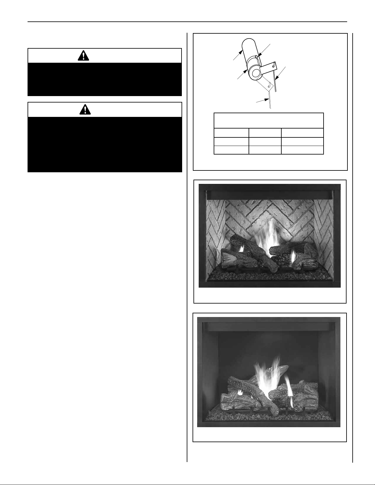
SUPERIOR® B-VENT GAS FIREPLACES • MODELS SLBV-35, SLBV-40 • INSTALLATION INSTRUCTIONS
Burner Air Shutter Adjustment Procedure
WARNING
• Air shutter adjustment should only be performed
by a qualified professional service technician.
• Ensure front glass panel are in place and sealed
during adjustment.
CAUTION
• Soot will be produced if the air shutter is closed
too much. Any damage due to sooting resulting
from improperly setting the air shutter is not
covered under the warranty.
• The air shutter door and nearby appliance surfaces
are hot. Exercise caution to avoid injury while
adjusting flame appearance.
1. Locate adjustment rod and adjust air shutter to the standard set-
ting as shown in Figure 26 (adjustment rod is located in the lower
control compartment).
Note: Move the adjustment rod DOWN to decrease air
and UP to increase air.
Adjustment Set-Screw
Adjustment
Rod Up
Burner
Tube
Air Shutter
Adjustment Rod Down
min. air opening position)
Main Burner Factory Air Shutter
Opening Setting - Inches (millimeter)
Model Nat.Gas Propane Gas
SLBV-35 1/32 (0.794) 1/16" (1.587)
SLBV-40 1/32 (0.794) 3/16" (4.763)
Figure 26: Burner Air Shutter Adjustment
(Fully Open
Position)
Ref. Air shutter Patent:
U.S. Pat. 5,553,603
2. Light appliance (follow lighting procedure on lighting label in con-
trol compartment or see the Care and Operation manual).
3. Allow the burner to operate for at least 15 minutes while observing
the flame continuously to ensure that the proper flame appearance has
been achieved (see Figure 27 and 28). If the following conditions
are present, adjust accordingly:
• If ame appears weak or sooty, adjust the air shutter, incrementally, to a more open position until the proper ame appearance is
achieved.
• If ame stays lowered blue, adjust the air shutter, incrementally,
to a more closed position until the proper flame appearance is
achieved.
4. Leave the control knob (off/pilot/on) in the ON position and the
burner OFF/ON switch OFF (and remote switches, if applicable).
5. When satised that the burner ame appearance is normal, re-
install the lower control compartment door then proceed to finish the
installation.
Figure 27: Burner Flame Appearance – Model SLBV-35
Figure 28: Burner Flame Appearance – Model SLBV-40
NOTE: DIAGRAMS & ILLUSTRATIONS ARE NOT TO SCALE.
21
Page 22
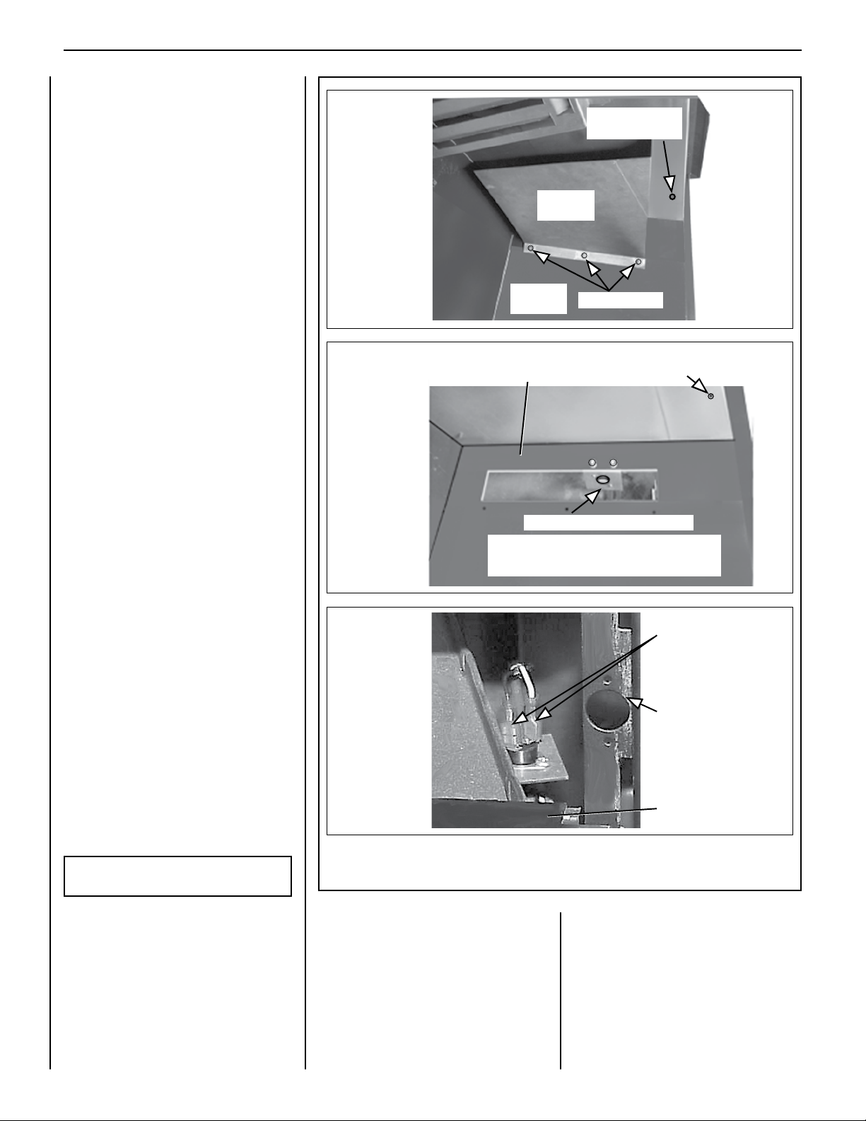
SUPERIOR® B-VENT GAS FIREPLACES • MODELS SLBV-35, SLBV-40 • INSTALLATION INSTRUCTIONS
Frame
Upper Right Side of Firebox
Lintel Screw Hole
Step 11. Perform Spillage Test
After appliance installation, perform this spillage
test to verify proper venting conditions:
1 - Place unit in its normally-operated condi-
tion, that is, with the glass enclosure panel
in place.
2 - Close all doors and windows in the room.
Turn on all exhaust fans in the house.
3 - Light the appliance.
4 - Wait 15 minutes.
5 - To check for venting action, start by hold-
ing a smoke producing device below the
glass enclosure panel. The smoke should
be drawn into the control compartment.
Continue the test by moving the smoke-
producing device along the entire length
of the lower edge of the glass enclosure
panel.
6 - If the smoke is NOT drawn into the con-
trol compartment, turn off the appliance
and call a qualified service technican.
Figure 29-A
Lintel Screw Hole
Right Side
Scoop
Right Side
of Firebox
(right side Scoop removed)
3 Scoop Screws
in Cabinet Top
in Cabinet Top
Manually-Reset Safety Limit Switch
This appliance is equipped with a manuallyreset safety limit switch in the upper RIGHT
side of the rebox, behind the right side scoop.
Refer to Figure 29 for its location.
If, during appliance operation, the flame
goes out (independently of the burner ON/
OFF switch), the safety limit switch may have
tripped.
Some causes for a tripped safety limit switch
include the following:
• Incorrect flue configuration
• Blocked flue
• Negative pressure inside house
Before resetting the safety limit switch, have
a qualified service technician inspect the
fireplace and venting for these conditions and
repair as needed.
To RESET the safety limit switch, push the
reset button located between the wire terminals
on the back of the switch. Follow the steps be-
low to access the switch (also see Figure 29-C).
To REPLACE the safety limit switch, follow
the steps below.
IMPORTANT: This procedure should only be
performed by a qualified service technician.
Figure 29-B
Figure 29-C
Figure 29
~
~
Bracket (right side Scoop removed)
To access the Safety Limit Switch, reach in and up
behind the Bracket, and push the red reset button
located between the two Wire Terminals.
~
~
Safety Limit Switch / Reset Button Location
Inside View of Firebox (upper right side)
Limit Switch
Wire Terminals
(Red reset button
is between the
two terminals.)
Cabinet
Corner
Door
1 - Turn OFF electrical power to appliance.
2 - Allow the appliance to cool.
3 - Remove the lower control compartment
access panel.
4 - Refer to Figure 25 on Page 20. Open both
latches under the rebox oor securing
the glass enclosure panel. Remove the
panel by tilting it outward at the bottom
and lifting it up. Set aside the panel, taking
22
care to protect it from damage.
5 - Remove the (3) screws securing the lintel,
and then remove the lintel. One of the lintel
cabinet top holes is shown in Figure 29.
6 - Remove the (3) screws securing the
scoop, and then remove the scoop. Refer
to Figure 29 for correct location for model
size.
7 - Reset the limit switch per Figure 29-B. If
unit does not reset, remove the (2) screws
securing the safety switch bracket, and
NOTE: DIAGRAMS & ILLUSTRATIONS ARE NOT TO SCALE.
pull the switch/bracket assembly (with
low voltage wires attached) through the
side panel slot into the rebox.
8 - Replace the switch, if necessary..
9 - Reinstall the scoop and lintel.
10 - Reinstall the glass enclosure panel and
control compartment access panel.
The appliance should then relight and remain
lit. If this does not occur, contact your dealer.
Page 23
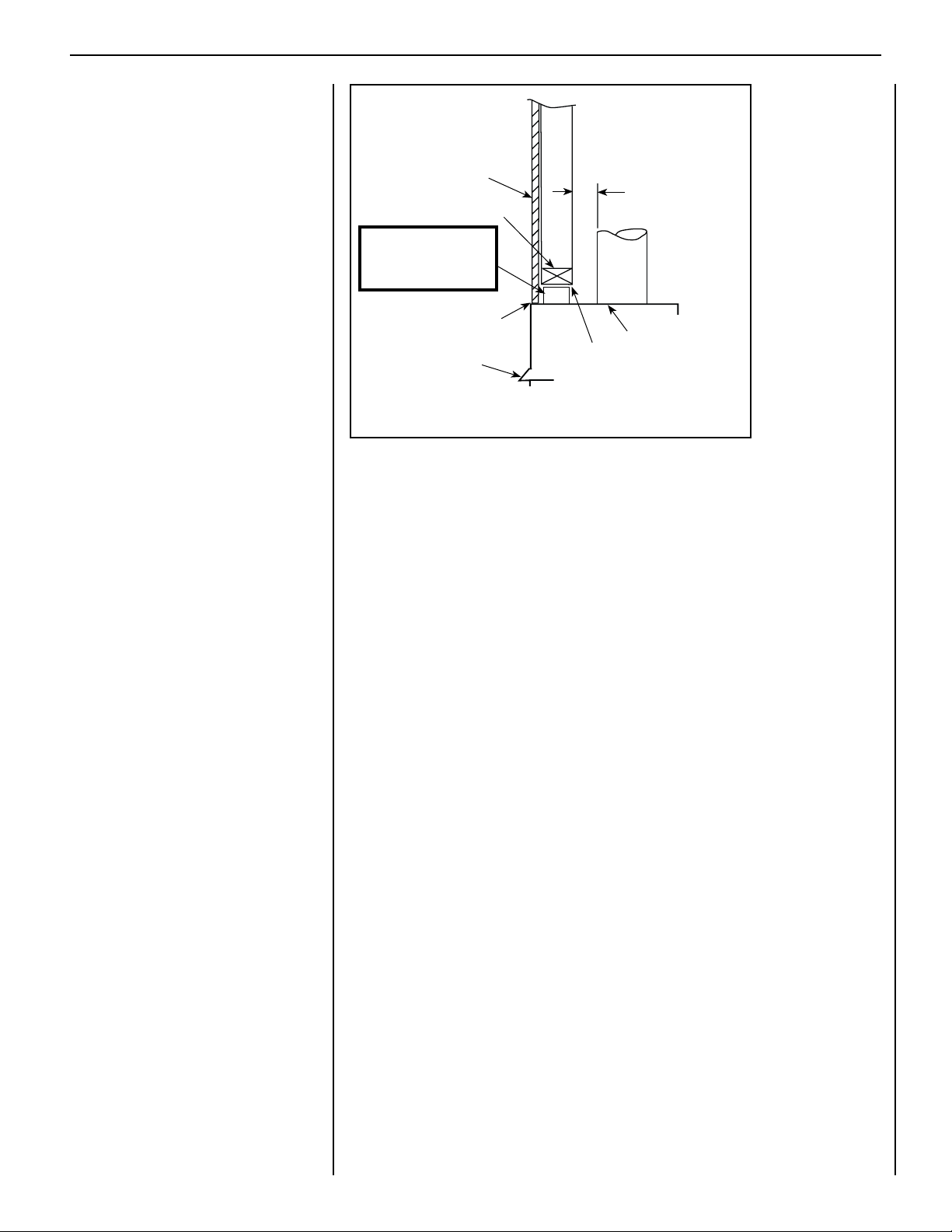
SUPERIOR® B-VENT GAS FIREPLACES • MODELS SLBV-35, SLBV-40 • INSTALLATION INSTRUCTIONS
Step 12. Install Hood
NOTE: All models must have a hood installed
prior to operating.
Refer to Figure 30. Install hood by sliding it into
the slots on the lower edge of the cabinet top.
Combustible Finished
Wall Materials
1 in (25 mm) min.
Header
Step 13. Finishing Requirements
Wall Details
Complete finished interior wall.
To install the appliance facing flush with the
nished wall, position framework to accommodate the thickness of the finished wall
(Figure 30).
For Cold Climate Insulation, see Page 5.
For Clearances, see Page 7.
IMPORTANT!
Bend up standoffs
to vertical position.
Combustible material
may touch appliance top.
Hood
Figure 30: Combustible Wall Framing
Top of Appliance
3" Clearance min.
NOTE: DIAGRAMS & ILLUSTRATIONS ARE NOT TO SCALE.
23
Page 24
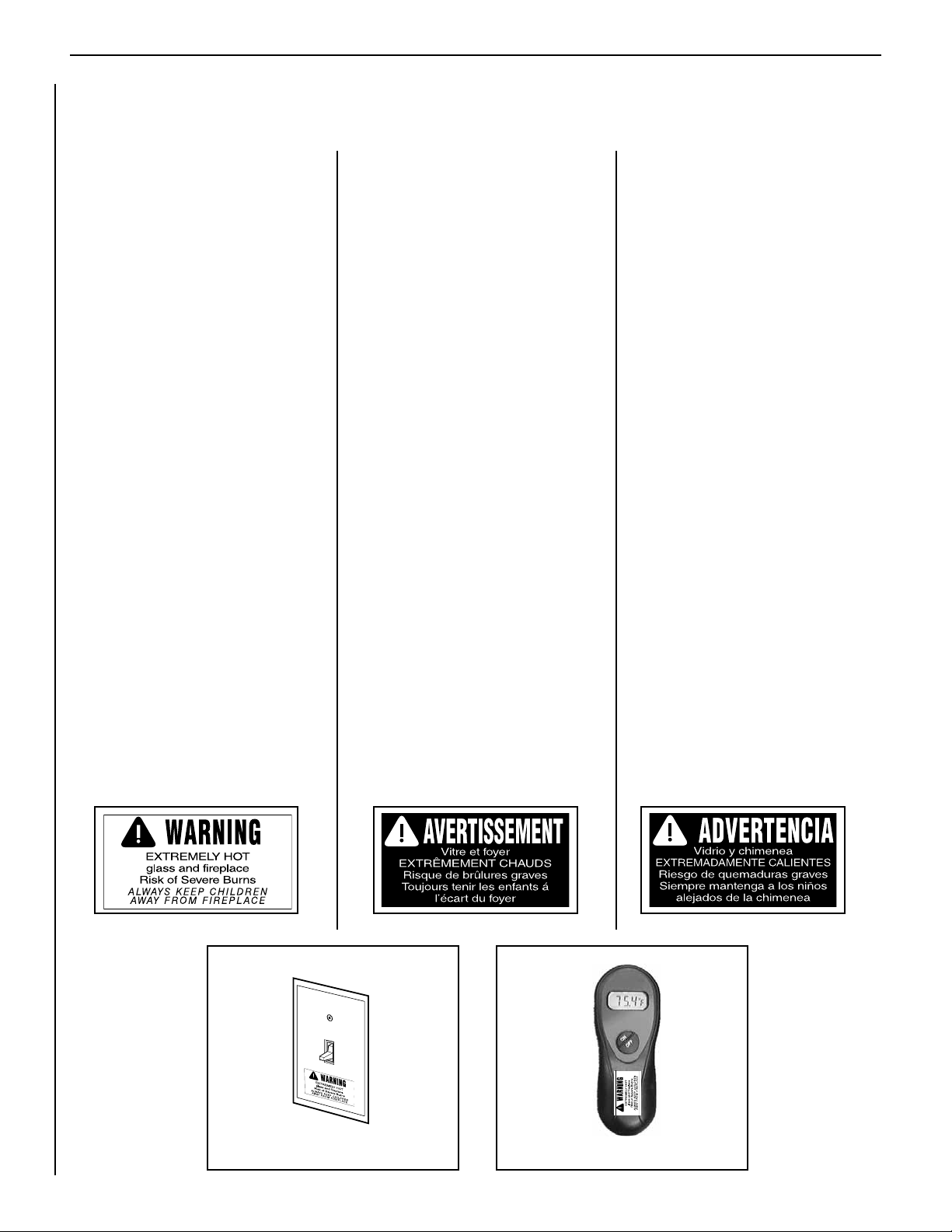
SUPERIOR® B-VENT GAS FIREPLACES • MODELS SLBV-35, SLBV-40 • INSTALLATION INSTRUCTIONS
Step 14. Attach Safety-In-Operation Warnings
It is the installer’s responsibility to ensure these warning labels are properly affixed during installation.
These warning labels are a critical step in informing consumers of the safe operation of this appliance.
ATTACHING SAFETY-IN-OPERATION
WARNINGS
It is required that the safety instruction labels furnished with the replace be afxed to the operation
and control point of the fireplace. A safety instruction
label must be afxed to the wall switch plate where
the fireplace is turned on and off (See Figure A) and
if used on the remote control handheld transmitter
(Figure B). To properly complete the installation of
this replace, locate the multi-lingual adhesive labels
provided with the Care and Operation Instructions
and proceed as follows:
1. Locate the wall switch that controls the fireplace
(verify the switch operates the replace by turning it on and off). Clean the wall switch plate
thoroughly to remove any dust and oils. Affix the
label to the surface of the plate of the wall switch
that controls the fireplace (Figure A). Choose
the language primarily spoken in the home. If
unknown, afx the English language label.
2. If a remote control is used to control the replace,
locate the transmitter and clean it thoroughly
to remove any dust and oils. Afx the label to
the surface of handheld transmitter (Figure B).
Choose the language primarily spoken in the
home. If unknown, afx the English language
label.
3. If you are unable to locate the labels, please call
Lennox Hearth Products or your nearest Lennox
Hearth Products dealer to receive additional
safety instruction labels free of charge.
Cat. No. H8024 Replacement Label Kit
LENNOX HEARTH PRODUCTS
1-800-9-LENNOX
Note: English is red text on clear label. French
and Spanish are white text on black label.
APPOSITION DES MISES EN GARDE RELATIVES
À LA SÉCURITÉ D’UTILISATION
Il est impératif que les étiquettes de sécurité fournies avec
le foyer soient collées à côté des dispositifs de contrôle
du foyer. Une étiquette de sécurité doit être collée sur la
plaque de l’interrupteur contrôlant l’allumage du foyer
(voir Figure A) et, le cas échéant, sur le boîtier de la
télécommande (Figure B). Pour achever l’installation
correcte de ce foyer, procédez comme suit avec les
étiquettes adhésives en langues étrangères fournies
avec les instructions d’utilisation et d’entretien :
1. Repérez l’interrupteur qui contrôle le foyer (vériez
que l’interrupteur contrôle le fonctionnement du
foyer en le faisant basculer de Marche à Arrêt, et
vice-versa). Nettoyez soigneusement la plaque
murale de l’interrupteur pour éliminer la poussière
et les traces de graisse ou d’huile. Collez l’étiquette
sur la surface de la plaque de l’interrupteur mural
qui contrôle le foyer (Figure A). Choisissez la
langue qui est principalement parlée dans la
résidence du propriétaire. En cas de doute, collez
l’étiquette en anglais.
2. Si une télécommande est utilisée pour contrôler
le foyer, nettoyez la soigneusement pour éliminer
la poussière et les traces de graisse ou d’huile.
Collez l’étiquette sur le boîtier de la télécommande
(Figure B). Choisissez la langue qui est principale-
ment parlée dans la résidence du propriétaire. En
cas de doute, collez l’étiquette en anglais.
3. Si vous ne trouvez pas les étiquettes, veuillez
appeler Lennox Hearth Products ou votre distribu-
teur Lennox Hearth Products local pour recevoir
gratuitement des étiquettes supplémentaires.
Étiquettes de remplacement, n° cat. H8024
LENNOX HEARTH PRODUCTS
1-800-9-LENNOX
Remarque : Le texte anglais est rouge sur un support
transparent. Le texte français et espagnol est blanc
sur un support noir.
COLOCACIÓN DE ADVERTENCIAS DE SEGURIDAD
EN OPERACIÓN
Se requiere que las etiquetas de instrucciones de
seguridad incluidas con la chimenea se coloquen en
el punto de operación y control de la misma. Se debe
colocar una etiqueta de instrucciones de seguridad
en la placa del interruptor de pared desde el cual se
enciende y se apaga la chimenea (ver la Figura A) y
en el transmisor de control remoto (Figura B) si se
usa. Para completar correctamente la instalación de
esta chimenea, encuentre las etiquetas adhesivas
multilingües incluidas con las instrucciones de cuidado
y operación y haga lo siguiente:
1. Identifique el interruptor de pared que controla
la chimenea (verifique que el interruptor opera la
chimenea encendiéndola y apagándola). Limpie bien
la placa del interruptor de pared para quitar el polvo
y aceite. Pegue la etiqueta en la superficie de la placa
del interruptor que controla la chimenea (Figura A).
Seleccione el idioma que más se habla en la casa.
Si no sabe cuál es, use la etiqueta en inglés.
2. Si se usa un control remoto para controlar la
chimenea, encuentre el transmisor y límpielo bien
para quitar el polvo y aceite. Pegue la etiqueta en
la superficie del transmisor (Figura B). Seleccione
el idioma que más se habla en la casa. Si no sabe
cuál es, use la etiqueta en inglés.
3. Si no puede encontrar las etiquetas, sírvase llamar a
Lennox Hearth Products o al distribuidor de Lennox
Hearth Products más cercano para recibir etiquetas
de instrucciones de seguridad adicionales gratuitas.
Juego de etiquetas de repuesto - Nº de cat. H8024
LENNOX HEARTH PRODUCTS
1-800-9-LENNOX
Nota: La etiqueta en inglés es transparente con texto
rojo. Las etiquetas en francés y español son negras
con texto blanco.
24
SAFETY LABEL
DIAGRAMS
Figure A Figure B
DIAGRAMMES DES ÉTIQUETTES
DE SÉCURITÉ
NOTE: DIAGRAMS & ILLUSTRATIONS ARE NOT TO SCALE.
DIAGRAMAS DE ETIQUETAS
DE SEGURIDAD
Page 25
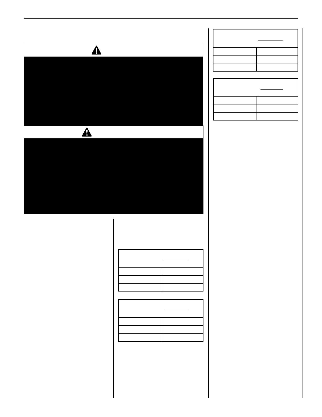
SUPERIOR® B-VENT GAS FIREPLACES • MODELS SLBV-35, SLBV-40 • INSTALLATION INSTRUCTIONS
GAS CONVERSION KITS
WARNING
This conversion kit shall be installed by a qualified service agency in
accordance with the manufacturer’s instructions and all applicable codes
and requirements of the authority having jurisdiction. If the information in
these instruction is not followed exactly, a fire, explosion or production of
carbon monoxide may result causing property damage, personal injury
or loss of life. The qualified service agency is responsible for the proper
installation of this kit. The installation is not proper and complete until the
operation of the converted appliance is checked as specified in the manufacturer’s instructions supplied with the kit.The qualified service agency
performing this installation assumes responsibility for this conversion.
AVERTISSEMENT
Cette trousse de conversion doit être installée par un technicien agréé,
selon les instructions du fabricant et selon toutes les exigences et tous les
codes pertinents de l’autorité compétente. Assurez-vous de bien suivre
les instructions dans cette notice pour réduire au minimum le risque
d’incendie, d’explosion ou la production de monoxyde de carbone pouvant
causer des dommages matériels, des blessures ou la mort. Le tecnicien
agréé est responsable de l’installation de cette trousse. L’installation n’est
pas adéquate ni complète tant que le bon fonctionnement de l’appareil
converti n’a pas été vérifié selon les instructions du fabricant fournies avec
la trousse. Le fournisseur de service qualifié ayant réalisé l'installation
assume les responsabilités liées à la conversion.
In Canada:
THE CONVERSION SHALL BE CARRIED
OUT IN ACCORDANCE WITH THE
REQUIREMENTS OF THE PROVINCIAL
AUTHORITIES HAVING JURISDICTION
AND IN ACCORDANCE WITH THE
REQUIREMENTS OF THE CAN/
CSA-B149.1 INSTALLATION CODE.
LA CONVERSION DEVRA ÊTRE
EFFECTUÉE CONFORMÉMENT
AUX RECOMMANDATIONS DES
AUTORITÉS PROVINCIALES AYANT
JURIDICTION ET CONFORMÉMENT
AUX EXIGENCES DU CODE
D'INSTALLATION CAN/CSA-B149.1.
Gas conversion kits are available to adapt your
appliance from the use of one type of gas to
the use of another. These kits contain all the
necessary components needed to complete the
task including labeling that must be afxed to
ensure safe operation.
Kit part numbers are listed here and the following steps detail the conversion procedure. Refer
to the instructions provided with the conversion
kit when performing any gas conversion.
Millivolt SIT Systems
Natural Gas To Propane Gas
Conversion Kits
Models Catalog No.
SLBV-35 H8270
SLBV-40 H7673
Millivolt SIT Systems
Propane Gas to Natural Gas
Conversion Kits
Models Catalog No.
SLBV-35 H8271
SLBV-40 H7675
NOTE: DIAGRAMS & ILLUSTRATIONS ARE NOT TO SCALE.
Electronic DEXEN Systems
Natural Gas To Propane Gas
Conversion Kits
Models Catalog No.
SLBV-35 H8268
SLBV-40 H7669
Electronic DEXEN Systems
Propane Gas To Natural Gas
Conversion Kits
Models Catalog No.
SLBV-35 H8269
SLBV-40 H7671
Gas Conversion Kit Installation
Instructions
Step 1. TURN OFF THE GAS SUPPLY TO THE
APPLIANCE and disconnect power
supply at the circuit breaker. Ensure
appliance is cold.
CAUTION: THE GAS SUPPLY SHALL BE
SHUT OFF PRIOR TO DISCONNECTING THE
ELECTRICAL POWER, BEFORE PROCEEDING WITH THE CONVERSION.
ATTENTION: AVANT D’EFFECTUER
LA CONVERSION, COUPEZ D’ABORD
L’ALIMENTATION EN GAZ, ENSUITE,
COUPEZ L’ALIMENTATION ÉLECTRIQUE.
Step 2. Remove the front glass enclosure
panel. See Figure 25 on Page 20.
Step 3. Carefully remove the logs.
Note: Logs are fragile. Handle gently
to prevent breakage.
Step 4. Refer to Figure 31. Remove the burner
assembly with attached venturi tube.
For Millivolt Systems, continue to Step 5.
For Electronic Systems, skip to Step 8.
Step 5. SIT Millivolt Valve: Refer to Figure 32
and the instructions provided with the
kit.
a. Using a Torx T20 (with 1/4" shank
and center hole), remove and dis-
card the three pressure regulator
mounting screws.
b. Remove the pressure regulator,
spring, poppet, diaphragm and
bushing.
c. Discard all removed components.
d. Make sure the rubber gasket in-
stalled on the back of the replace-
ment pressure regulator is properly
positioned. Tighten screws to 25
in.-lb. torque.
25
Page 26
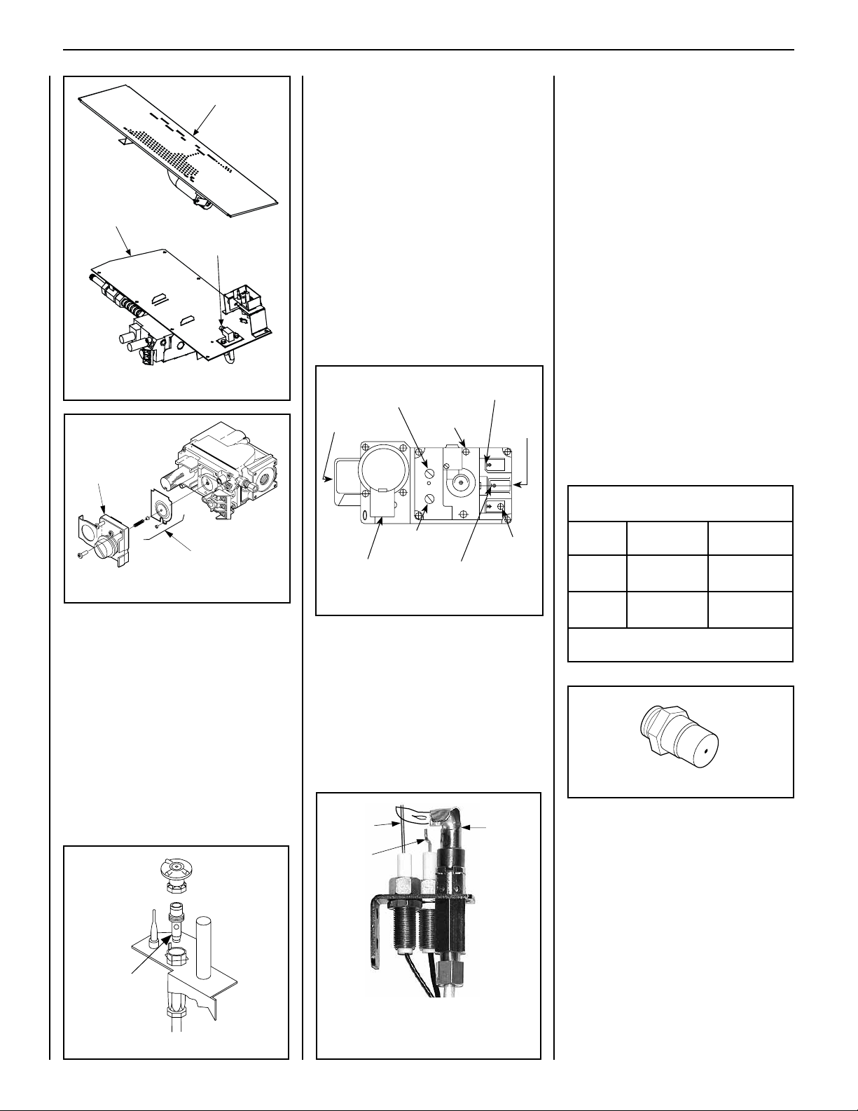
PILOT
OUT
VENT
LO
TH
TP
TH
TP
HI
IN
IN
SUPERIOR® B-VENT GAS FIREPLACES • MODELS SLBV-35, SLBV-40 • INSTALLATION INSTRUCTIONS
ELECTRONIC
Burner Assembly
Gas Valve
Assembly
Orifice
Figure 31: SIT Millivolt System
Pressure
Regulator
Electronic Appliances
Step 8. Dexen Electronic Valves: Refer to
Figure 34 and the instructions provided with the kit.
a. Remove and discard the two pres-
sure regulator mounting screws.
b. Remove the pressure regulator and
diaphragm.
c. Discard all removed components.
d. Make sure the provided diaphragm
is installed properly onto the replacement pressure regulator.
e. Install the new pressure regulator
using the new screws supplied with
the kit; tighten the screws.
Supply Gas
Inlet
Pressure-Tap
(Manifold)
Regulator
Mounting
Screw
Burner Stage
Terminal
Gas
Outlet
To Burner
All Models
Note the following:
Use pipe joint compound or Teflon tape on
all pipe fittings before installing.
Ensure propane-resistant compounds are
used in propane applications.
Do NOT use pipe joint compounds on flare
fittings.
Step 10. Refer to Figure 31.
a. VERIFY PROPER ORIFICE SIZE
BEFORE INSTALLING IT.
b. Remove the orice from the mani-
fold and replace it with the one
provided in the kit. See Table 7 for
orifice sizes for natural and propane
models. Figure 36 illustrates the
orifice. Always check and verify
orifice size.
c. Retrieve the burner. Slide the venturi
tube over the orice.
d. Adjust the burner air shutter as
shown in Figure 26 on Page 21.
Remove
These
Components
Figure 32: SIT Millivolt System
Step 6. (Millivolt systems only): Attach ma-
nometer to the manifold side pressure
test fitting and verify manifold pressure
reads 3.5 inches water column (0.87
kPa) for natural gas, and 10.0 inches
water column (2.49 kPa) for propane
gas.
Step 7. (Millivolt systems only): Refer to Figure
33. Remove the pilot hood assembly to
access the hexed pilot orifice. Remove
and replace the orifice with the one
provided in the kit.
Skip to Step 10.
Pressure-Tap
(Inlet)
Pilot Gas Outlet
Ground (TP)
Pilot Stage
Terminal
Figure 34: Dexen Electronic Gas Valve
Step 9. Refer to Figure 35. Follow these steps
to replace the pilot orifice:
a. Remove pilot hood assembly to
access the phillipped pilot orifice.
b. Remove and replace the orice
with the one provided with the kit.
Exercise extreme care to prevent
damage to or breakage of the
igniter assembly.
Sensor
Igniter
Pilot
Hood
Burner Orifice Sizes
Elevation 0-4500 feet ( 0-1372 meters)
Model
Series
SLBV-35
SLBV-40
Table 7
Nat.Gas
drill size (inches)
#48 (0.076")*
H1236•
#43 (0.089")*
99K75•
Standard size installed at factory.
*
• Part /Cat. Number.
Propane
drill size (inches)
#56 (0.046")*
62L37•
#55 (0.052")*
19L52•
Figure 36
Step 11. Reassemble the remaining compo-
nents by reversing the procedures
outlined in the preceding steps.
Step 12. Attach the conversion label (provided
in the conversion kit) next to the rating plate on the appliance.
Step 13. Turn on gas supply and test for gas
leaks (refer to Page 16).
Pilot
Orifice
ALWAYS TEST PRESSURES WITH THE VALVE
REGULATOR CONTROL AT THE HIGHEST
SETTING.
Figure 33: SIT Millivolt System
26
Figure 35: Dexen Electronic System
NOTE: DIAGRAMS & ILLUSTRATIONS ARE NOT TO SCALE.
Page 27

Notes
SUPERIOR® B-VENT GAS FIREPLACES • MODELS SLBV-35, SLBV-40 • INSTALLATION INSTRUCTIONS
NOTE: DIAGRAMS & ILLUSTRATIONS ARE NOT TO SCALE.
27
Page 28

SUPERIOR® B-VENT GAS FIREPLACES • MODELS SLBV-35, SLBV-40 • INSTALLATION INSTRUCTIONS
Lennox Hearth Products reserves the right to make changes at any time, without notice, in design,
materials, specications, prices and also to discontinue colors, styles and products.
Consult your local distributor for replace code information.
Printed in U.S.A. © 2010 Lennox Hearth Products
P/N 506009-02 Rev. B 06/2011
LENNOX HEARTH PRODUCTS
1508ElmHillPike,Suite108•Nashville,TN37210
 Loading...