

Superior SAMANTA THERMO 11, SVEVA THERMO 11, SABRINA THERMO 11, SIRIA THERMO 11 Instructions For Installation, Use And Maintenance Manual
Page 1
1
SAMANTA THERMO 11, SABRINA THERMO 11,
SVEVA THERMO 11, SIRIA THERMO 11
Page 2

2
PIAZZETTA PELLET BOILERS AND STOVES
SUPPLEMENTARY INSTALLATION INSTRUCTIONS FOR THE UK MARKET
TO BE READ IN CONJUNCTION WITH THOSE IN THE INSTRUCTION BOOKLET
Please note that it is a legal requirement under England and Wales Building Regulations
that the installation of the stove is either carried out under Local Authority Building Control
approval or is installed by a Competent Person registered with a Government approved
Competent Persons Scheme. HETAS Ltd operate such a Scheme and a listing of their
Registered Competent Persons can be found on their website at www.hetas.co.uk.
CO Alarms:Building regulations require that when ever a new or replacement fixed solid fuel or wood/biomass
appliance is installed in a dwelling a carbon monoxide alarm must be fitted in the same room as the
appliance. Further guidance on the installation of the carbon monoxide alarm is available in BS EN
50292:2002 and from the alarm manufacturer’s instructions.
Provision of an alarm must not be considered a substitute for either installing the appliance
correctly or ensuring regular servicing and maintenance of the appliance and chimney system.
HEALTH AND SAFETY PRECAUTIONS
Special care must be taken when installing the stove such that the requirements of the Health and Safety at
Work Act are met.
Handling
Adequate facilities must be available for loading, unloading and site handling.
Fire Cement
Some types of fire cement are caustic and should not be allowed to come into contact with the skin. In case
of contact wash immediately with plenty of water.
Asbestos
This stove contains no asbestos. If there is a possibility of disturbing any asbestos in the course of
installation then please seek specialist guidance and use appropriate protective equipment.
Metal Parts
When installing or servicing this stove care should be taken to avoid the possibility of personal injury.
READ THE INSTRUCTION BOOKLET AND THESE SUPPLEMENTARY
INSTRUCTIONS CAREFULLY BEFORE INSTALLATION
These instructions together with those in the instruction booklet cover the basic principles
to ensure the satisfactory installation of the stove, although detail may need slight
modification to suit particular local site conditions.
In all cases the installation must comply with current Building Regulations, Local Authority
Byelaws and other specifications or regulations as they affect the installation of the stove.
It should be noted that the Building Regulations requirements may be met by adopting the
relevant recommendations given in British Standards BS 8303, BS EN 15287-1:2007 as an
alternative means to achieve an equivalent level of performance to that obtained following the
guidance given in Approved Document J.
Page 3

3
PREPARATORY WORK AND SAFETY CHECKS
IMPORTANT WARNING
This stove must not be installed into a chimney that serves any other heating appliance.
There must not be an extractor fan fitted in the same room as the stove as this can cause the stove to emit
fumes into the room.
Chimney
Note: The flue is under a small positive pressure so all flue joints must be sealed with a suitable
high temperature silicone sealant to ensure there is no flue product leakage into the room.
For the stove to perform satisfactorily the chimney height must be sufficient to ensure an adequate draught
of approximately 12 Pa so as to clear the products of combustion and prevent smoke problems into the
room.
NOTE: A chimney height of not less than 3.5 metres measured vertically from the outlet of the stove to the
top of the chimney should be satisfactory. If using factory made metal flue pipe refer to the detailed
appliance instructions. Alternatively the calculation procedure given in EN 13384-1 may be used as the
basis for deciding whether a particular chimney design will provide sufficient draught.
Please Note, this appliance has been tested by the manufacturers and works
on a 3.5m straight flue.
The outlet from the chimney should be above the roof of the building in accordance with the provisions of
Building Regulations Approved Document J.
If installation is into an existing chimney then it is essential that it is sound and have no cracks or other faults
which might allow fumes into the house. Remedial action should be taken, if required, seeking expert
advice, if necessary. If it is found necessary to line the chimney then a flue liner suitable for solid fuel must
be used in accordance with Building Regulations Approved Document J.
Any existing chimney must be clear of obstruction and have been swept clean immediately before
installation of the stove. If the stove is fitted in place of an open fire then the chimney should be swept one
month after installation to clear any soot falls which may have occurred due to the difference in combustion
between the stove and the open fire.
If there is no existing chimney then either a prefabricated block chimney in accordance with Building
Regulations Approved Document J or a twin walled insulated stainless steel flue to BS 4543 can be used.
These chimneys must be fitted in accordance with the manufacturer’s instructions and Building Regulations.
Please Note, pellet stoves have a flue outlet size of 80mm and are suitable for
use with 100 and / or 125mm flues depending on site conditions.
Please refer to Robeys website, Brochure Downloads / Help & Advice for flue
sizes etc.
Any bend in the chimney or connecting fluepipe should not exceed 45°. 90° bends should not be used
except at the stove connection to the flue.
Combustible material should not be located where the heat dissipating through the walls of fireplaces or
flues could ignite it. Therefore when installing the stove in the presence of combustible materials due
account must be taken of the guidance on the separation of combustible material given in Building
Regulations Approved Document J and also in these stove instructions.
Page 4

4
Adequate provision e.g. easily accessible soot door or doors must be provided for sweeping the chimney
and connecting fluepipe, also to permit visual checks on the integrity of the flue when the appliance is
serviced. Ensure that all access doors in the flue can be adequately sealed after service.
Hearth
The hearth should be able to accommodate the weight of the stove and its chimney if the chimney is not
independently supported. The weight of the stove is indicated in the brochure.
The stove should always be installed on a non-combustible hearth or base of a size and construction that is
in accordance with the provisions of the current Building Regulations Approved Document J.
The clearance distances to combustible material beneath, surrounding or upon the hearth and walls
adjacent to the hearth should comply with the guidance on the separation of combustible material given in
Building Regulations Approved Document J and also in these stove instructions.
If the stove is to be installed on a combustible floor surface, it must be covered with a
non-combustible material at least 12mm thick and extending in front and to the sides of the
stove as shown in the detailed instructions, and in accordance with Building Regulations
Approved Document J.
Combustion air supply
In order for the stove to perform efficiently and safely there should be an adequate air supply into the room
in which the stove is installed to provide combustion air. This is particularly necessary if the room is
double-glazed and well sealed. It may be necessary to increase the air vent size in property with low air
permeability ( < 5.0 m3 /(h.m2).
The provision of air supply to the stove must have a total free area at least equal to the size given in the
Technical Data section in the instructions and be in accordance with current Building Regulations Approved
Document J. An opening window is not appropriate for this purpose.
IMPORTANT NOTE: If applicable and the appliance is being fitted within a fireplace recess, specialist
advice should be sought before fitting any permanent ventilation within this area.
For inset stoves built into a fireplace or enclosure, convection air vents must be fitted at high and low level to
ventilate the chamber with minimum free area as stated in the Technical Data section.
Connection to chimney
Stoves have a rear flue connector that allows connection to either a masonry chimney or a prefabricated
factory made insulated metal chimney in accordance with the instructions. In some cases it will be
necessary to fit an adaptor to increase the diameter of the flue to the 150 mm section of the chimney or
liner. Ensure that there is access to sweep the flue completely including the internal parts of the stove.
Electrical Services
The installation of any electrical services during the installation of this appliance must be carried out by a
registered competent electrician and in accordance with the requirements of the latest issue of BS 7671
Carbon Monoxide Alarm
A carbon monoxide alarm complying with BS EN 50292 must be fitted in the same room as the appliance. It
should be positioned on the ceiling at least 300mm from any wall or, if it is located on a wall, as high up as
possible (above any doors and windows) but not within 150mm of the ceiling. The alarm should also be
between 1m and 3m horizontally from the appliance.
Commissioning and handover
Ensure loose parts are fitted in accordance with the instructions given in the instruction booklet.
On completion of the installation allow a suitable period of time for any sealants and cement to dry out. On
Thermo boiler stoves ensure that the system and stove has been fully vented and that system controls are
operating before lighting. When lit check to ensure that all smoke and fumes are taken from the stove up the
chimney and emitted safely to atmosphere. Follow the detailed instructions in the relevant section.
Page 5

5
On completion of the installation and commissioning ensure that the operating instructions for the stove are
left with the customer. Ensure to advise the customer on the correct use of the appliance. Advise the correct
pellet fuel to be used on the stove and warn them to use only the recommended fuels for the stove. It is
important that the fuel is stored in a dry place, particularly once a bag is opened. If bulk fuel storage is used
expert advice should be sought.
Advise the user what to do should smoke or fumes be emitted from the stove. The customer should be
warned to use a fireguard to BS 8423:2002 in the presence of children, aged and/or infirm persons.
SUPPLEMENTARY OPERATING INSTRUCTIONS FOR THE UK MARKET
TO BE READ IN CONJUNCTION WITH THOSE IN THE INSTRUCTION BOOKLET
WARNING NOTE
Properly installed, operated and maintained this stove will not emit fumes into the dwelling. Fume emission
is potentially dangerous and must not be tolerated. In the event of fume emission from the appliance, then
the following immediate action should be taken: ‑
(a) Switch off the stove immediately
(b) Open doors and windows to ventilate room and then leave the premises
(c) When safe to do so, check for flue or chimney blockage and clean if required
(d) Do not attempt to relight the stove until the cause of the fume emission has been identified and corrected.
If necessary seek expert advice.
The most common cause of fume emission is flueway or chimney blockage. For your own safety these must
be kept clean at all times.
IMPORTANT NOTES
General
Before lighting the stove check with the installer that the installation work and commissioning checks
described in the installation instructions have been carried out correctly and that the chimney is clean, sound
and free from any obstructions. As part of the stoves’ commissioning and handover the installer should have
shown you how to operate the stove correctly.
CO Alarm
Your installer should have fitted a CO alarm in the same room as the appliance. If the alarm sounds
unexpectedly, follow the instructions given under “Warning Note” above.
Use of fireguard
When using the stove in situations where children, aged and/or infirm persons are present a fireguard must
be used to prevent accidental contact with the stove. The fireguard should be manufactured in accordance
with BS 8423:2002.
READ THE INSTRUCTION BOOKLET AND THESE INSTRUCTIONS CAREFULLY
BEFORE USING THE STOVE
Page 6

6
Chimney cleaning
The chimney should be swept at least twice a year. It is important that the flue connection and chimney are
swept prior to lighting up after a prolonged shutdown period.
The installer will have provided access for flue cleaning, such as a soot door. After sweeping the chimney
the stove flue outlet and the flue pipe connecting the stove to the chimney must be cleaned. It is essential
that all seals are secure and effective before reusing the stove. This must only be carried out by suitably
qualified personnel.
Periods of Prolonged Non-Use
If the stove is to be left unused for a prolonged period of time then it should be given a thorough clean to
remove ash and unburned fuel residues.
Extractor fan
There must not be an extractor fan fitted in the same room as the stove as this can cause the stove to
malfunction and emit smoke and fumes into the room.
Aerosol sprays
Do not use an aerosol spray on or near the stove when it is alight.
Chimney Fires
If the chimney/flue is thoroughly and regularly swept, chimney fires should not occur. However, in the
unlikely event of a chimney fire turn off the stove immediately and isolate the mains electricity supply. Do not
open the door of the stove. This should cause the chimney fire to go out. If the chimney fire does not go out
when the above action is taken then the fire brigade should be called immediately. Do not relight until the
stove, chimney and flueways have been cleaned and examined by a professional.
Permanent air vent
The stove requires a permanent and adequate air supply in order for it to operate safely and efficiently.
In accordance with current Building Regulations and the instructions the installer will have fitted a permanent
air supply vent into the room in which the stove is installed to provide combustion air. This air vent should
not under any circumstances be shut off or sealed.
Page 7

7
USER OPERATING INSTRUCTIONS
Please read the important notices given above before referring to the main instruction book for detailed
operating instructions.
Recommended fuels
The stoves are designed to burn good quality wood pellets only, no other fuel can be used. The pellets must
be kept dry at all times otherwise malfunction can occur. Check the section ‘Fuels’ for detailed specification.
Do not attempt to burn rubbish on the stove.
Door operation
Do not open the door during operation, the door and its seal are important functional components. If the
door is accidentally opened whilst the stove is running it will switch off.
Lighting of fire
Ensure the grate and support are cleaned and free of any unburned pellets before use. Do not empty the
grate into the hopper. Check the hopper contains sufficient fuel. On boiler stoves ensure that the water
system is full, set to the correct pressure and the controls are working satisfactorily. The installer will have
explained use of the controls.
The stove can be lit and programmed using the keypad on the stove or (where applicable) the remote
control. See the detailed instructions. The ignition and operation of the stove is then automatically controlled
and monitored by the control system. Do not be concerned if the stove appears to be inactive for several
minutes during the ignition process as it goes through various self checks. Do not be tempted to open the
door as this will stop the ignition process.
Refuelling
Keep the hopper well filled but do not allow fuel to spill into the top of the stove.
Cleaning and maintenance
The instructions detailed in the section “Maintenance” in the instruction booklet should be followed. The
grate and glass should be cleaned daily and other items at the specified intervals as shown in the
instructions.
Spare Parts
Spare parts can be obtained from Robeys Limited. Telephone 01773 820 940
Trouble shooting
The instructions detailed in the relevant section in the instruction booklet should be followed.
Page 8
8
Page 9
9
SECTION TITLE PAGE
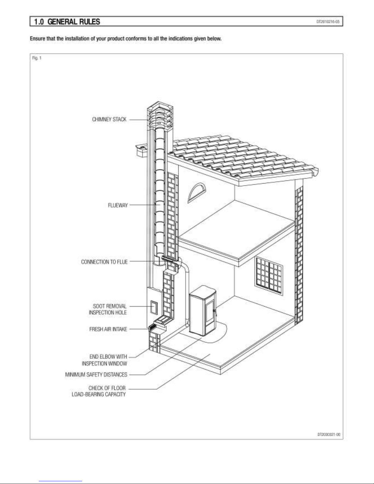
1.0 GENERAL RULES 10
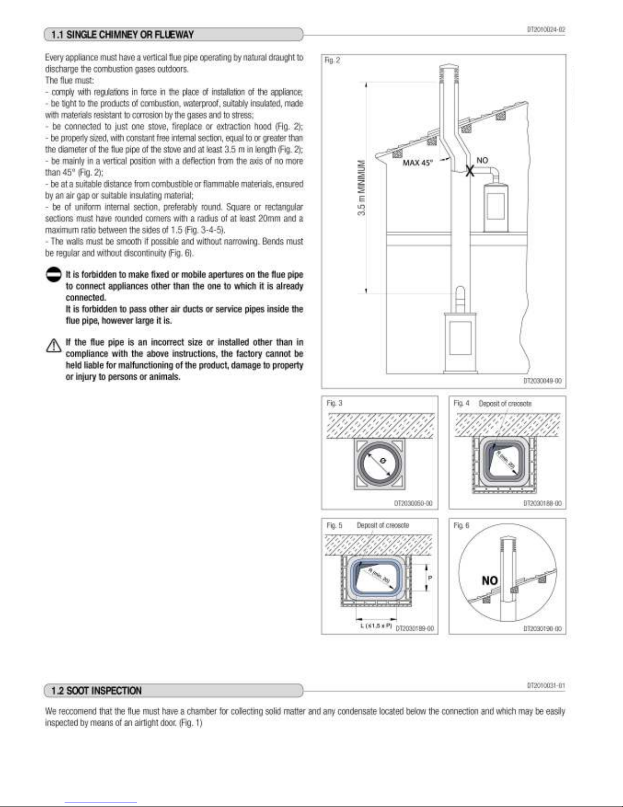
1.1 SINGLE FLUEWAY OR CHIMNEY 11
1.2 SOOT INSPECTION 11
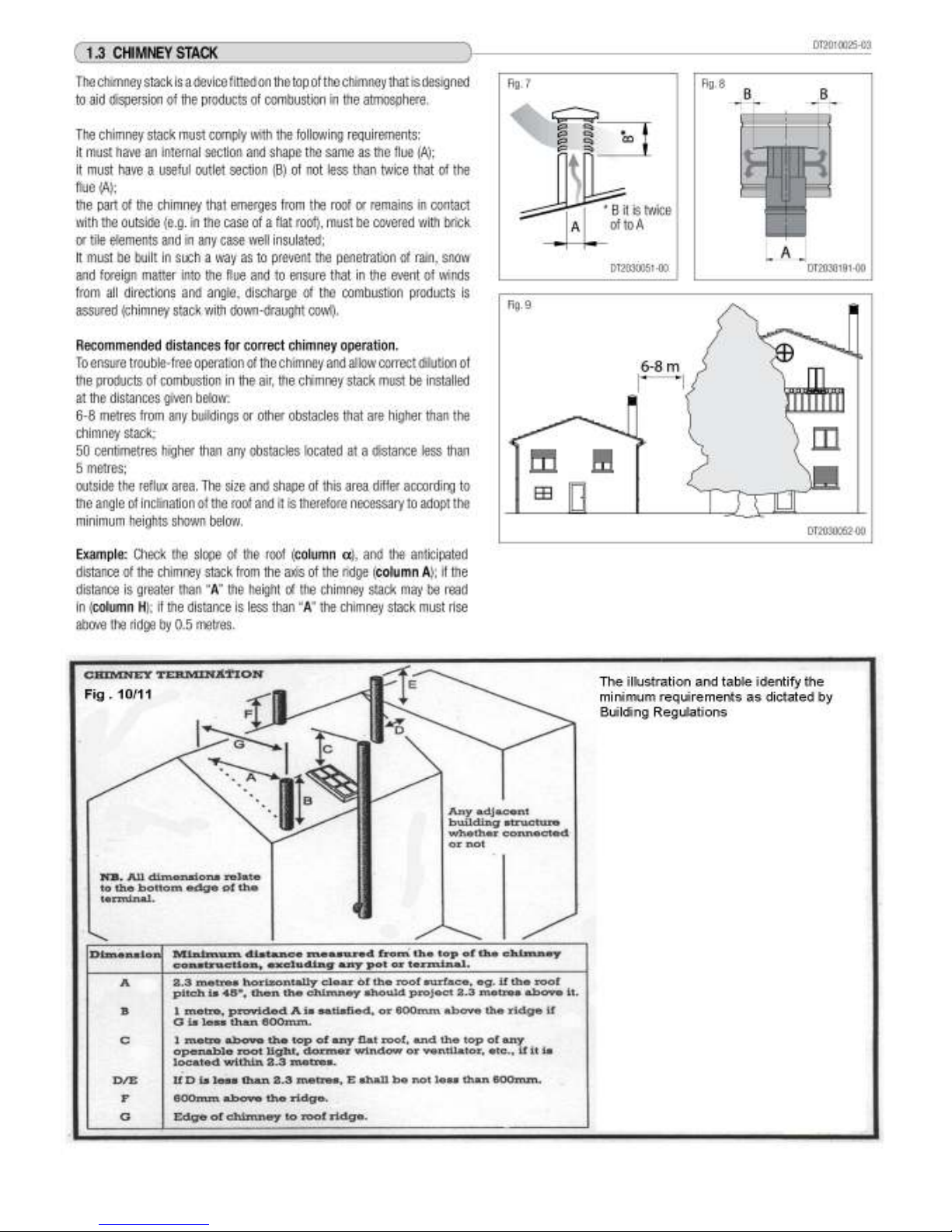
1.3 CHIMNEY STACK 12
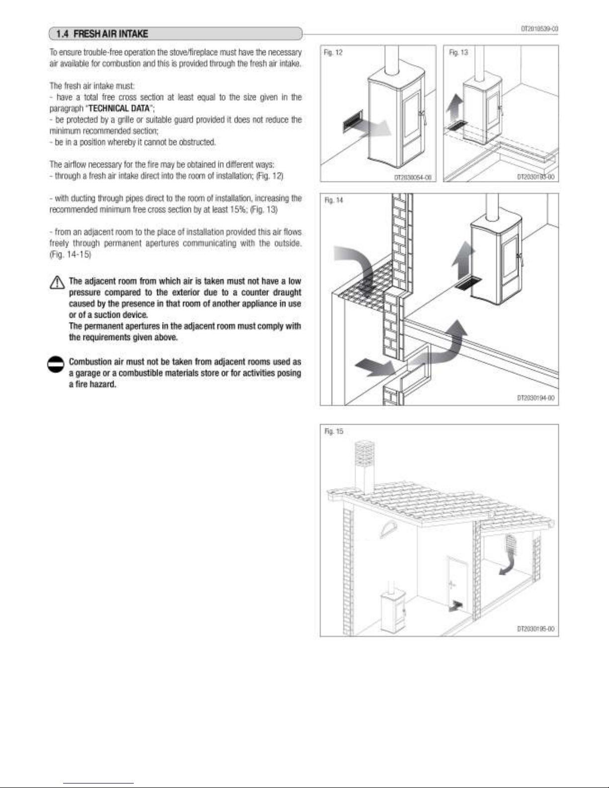
1.4 FRESH AIR INTAKE 13
1.5 INSTALLATION ENVIRONMENT 14
1.6 LOAD CAPACITY OF THE FLOOR 14
1.7 HEATING CAPACITY 14
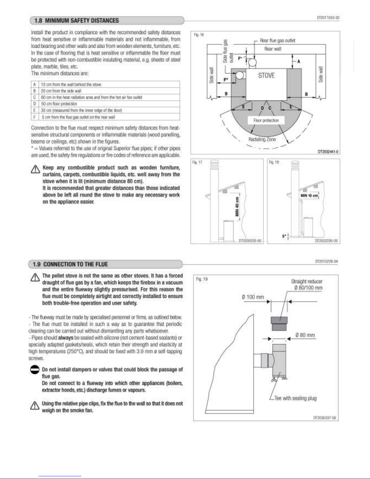
1.8 MINIMUM SAFETY DISTANCES 15
1.9 CONNECTION TO THE FLUE 15
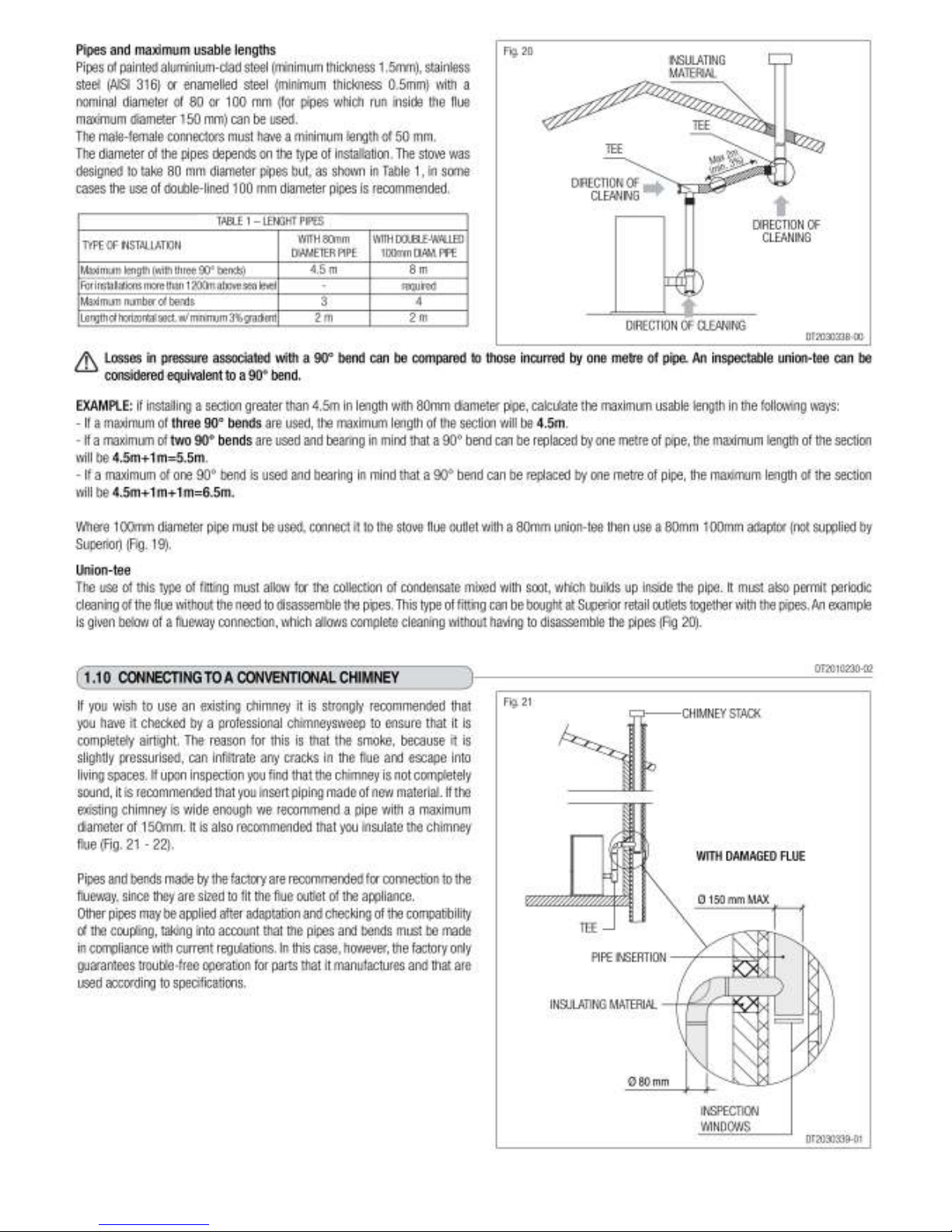
1.10 CONNECTING TO A CONVENTIONAL CHIMNEY 16
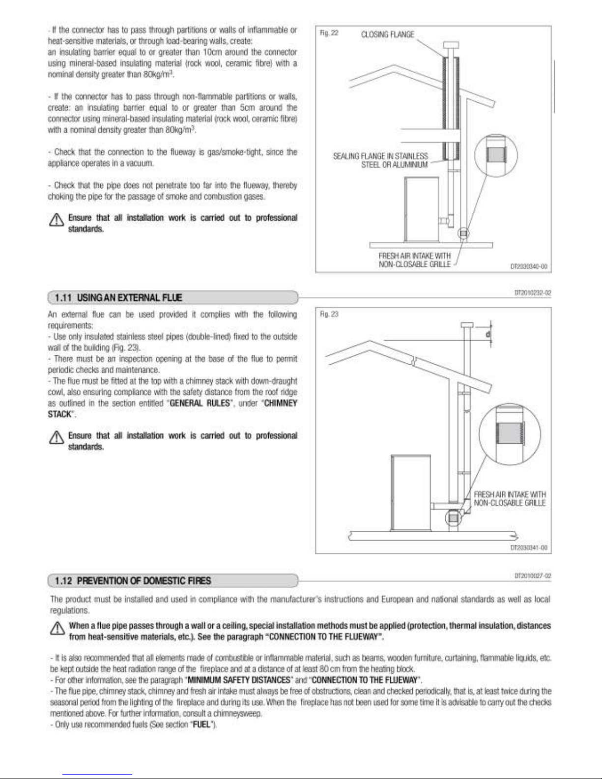
1.11 USING AN EXTERNAL FLUE 17
1.12 PREVENTION OF DOMESTIC FIRES 17
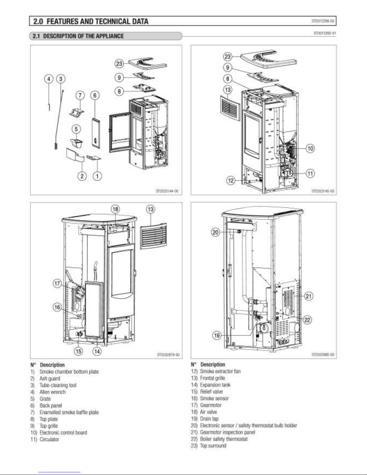
2.0 FEATURES AND TECHNICAL DATA 18
2.1 FEATURES 18
2.2 TECHNICAL DATA 19
2.3 FEATURES 20
2.4 ACCESSORIES AND EQUIPMENT 20
2.5 PRODUCT IDENTIFICATION DATA 19
2.6 DIMENSIONS 21
2.7 WIRING DIAGRAM 22
3.0 PREPARING FOR INSTALLATION 23
4.0 INSTALLATION 23
4.1 REMOVING THE CLADDING 23
4.2 WATER CONNECTIONS 24
4.3 WATER PIPE CONNECTIONS 25
4.4 ELECTRICAL CONNECTIONS AND CONTROLS 26
4.5 INSTALLING THE EXTERNAL THERMOSTAT 26
4.6 INSTALLING THE AUX THERMOSTAT 27
4.7 FILLING THE SYSTEM 27
4.8 SIDE FLUE GAS OUTLET ( OPTIONAL ) 28
5.0 FUEL 30
5.1 LOADING THE PELLETTS 30
6.0 USE 31
6.1 CONTROL PANEL 31
6.2 SETTING THE LANGUAGE 32
6.3 PROGRAMMING 32
6.4 PROGRAMMING THE CLOCK 33
6.5 TIMER 33
6.6 PARAMETERS MENU 36
6.7 BUZZER ENABLE 37
6.8 LIGHTING FOR THE FIRST TIME 37
6.9 LIGHTING AND NORMAL OPERATION 37
6.10 SAFETY DEVICES 41
6.11 STOVE STATUS 43
6.12 OPENING THE DOOR 43
6.13 FROST PROTECTION MODE 44
6.14 DISPOSAL OF ASHES 44
7.0 MAINTENANCE 45
7.1 CLEANING THE GRAT AND GRATE SUPPORT 45
7.2 CLEANING THE ASH TRAY 45
7.3 CLEANING THE FIREBOX 45
7.4 CLEANING THE SMOKE CHAMBER AND BOILER 46
7.5 CLEANING THE FLUE SYSTEM 47
7.6 CLEANING THE CERAMIC CLADDING 47
7.7 CLEANING THE ENAMELLED METAL PARTS 47
7.8 CLEANING THE GLASS ( DAILY ) 47
7.9 REPLACING THE GLASS 47
7.10 SUTTING DOWN 48
7.11 PROGRAMMING MAINTENANCE 48
8.0 TROUBLESHOOTING 49
8.1 REPLACING THE FUSES 52
CERTIFICATE OF CONFORMITY 53
WIRING DIAGRAMS 54
FLUE PARAMETER SETTING GUIDE 58
Page 10
10
N
O
T
F
O
R
U
K
U
S
E
Page 11
11
Page 12
12
Page 13
13
Page 14
14
Page 15
15
Page 16
16
NOT F
O
R UK USE
NOT F
O
R UK USE
Page 17
17
Page 18
18
Page 19

19
Page 20

20
Page 21

21
Page 22

22
Page 23

23
Page 24

24
Page 25

25
Page 26

26
The appliance is designed for connection to an external room
thermostat (NOT SUPPLIED). To connect an external thermostat use a
2x0.5mm2 cable, clamped with a PG7 cable gland inserted in the
appropriate hole in the rear panel (Fig. 32 ).
Page 27

27
Page 28

28
Page 29

29
Page 30

30
Do not allow sawdust to accumulate on the bottom of the
hopper.
Do not leave leftover pellets on top of the stove - they could
catch fire!
Page 31

31
Page 32

32
Page 33

33
Page 34

34
Page 35

35
Page 36

36
Page 37

37
Page 38

38
Page 39

39
Page 40

40
Page 41

41
Page 42

42
Page 43

43
Page 44

44
Page 45

45
Page 46

46
Page 47

47
Page 48

48
Page 49

49
Page 50

50
Page 51

51
Page 52

52
Page 53

53
Page 54

54
Page 55

55
Page 56

56
Page 57

57
Page 58

58
Piazzetta Pellet Stove Guide to Setting Flue Parameters (Installer Information Only)
This guide is supplementary to the Installation Instructions, which should be read before setting the flue fan
parameters. It must only be carried out by an authorised installation engineer with the correct equipment. Whilst
the appliance will normally operate as set in the factory, for optimum performance the flue gas fan must be
adjusted to allow for variations in individual flues.
General
Before starting ensure the hopper contains enough pellets. Pellets must be fresh and dry. Remove any unburnt
pellets and ash from the grate.
Ensure any controls (boiler stove) are calling for heat.
Note that the first ignition attempt may fail to ‘No lit’ as the auger takes time to fill before dropping pellets into the
grate. If this happens restart the stove.
Connect a suitable micromanometer / draught gauge to the pressure tapping point on the rear of the stove
(remove brass cap nut). The draught gauge needs to measure values of up to about 120 Pascals (Pa) with 1 Pa
steps. (A gas CO / CO2 analyser such as the Anton Sprint usually have a suitable pressure scale). Note the
pressures are negative.
Record the pressure at each setting after adjustment for future reference.
See relevant section as to using the remote or the keypad (always use the remote where it is supplied)
Setting Parameters using the Remote Control
Start the appliance.
Open the flap on the remote and follow the procedure in sequence
Note: esc returns you to the previous memory, set confirms the menu or setting
ο
Press menu
ο
Use the up/ down arrows to find menu parameter
ο
Press set
ο
Use the up/ down arrows to find setting smoke ext
ο
Press set
ο
Use the up/ down arrows to find A9
ο
Press set
ο
Use the set button to scroll through the parameters and adjust each one as necessary as you get to it. If you
pass the parameter you need to adjust press esc to return to the previous menu and start again.
Check and adjust if necessary parameter 16P. Note this must be done during Phase 1
Note: The setting value of the parameter is adjusted using the up/ down arrows and watching the
micromanometer to obtain the correct pressure. Changes to the pressure are immediate but wait for it to settle
and record the final result (Pa).
ο
Press set to confirm the setting and move to the next parameter
Parameter 17P must be set during Phase 2 adjusting as above to obtain the correct pressure
The rest of the parameters must be set when the whole flue system is up to temperature. For boiler stoves the
water temperature must also be at least 60 deg C.
Note the parameters 18P to 22P are the settings for the different power output levels 1-5, or for stoves with 4
power levels 18P to 21P
ο
Access the highest power level (22P or 21P) first using the method above
ο
Adjust the setting to obtain the correct pressure and set to confirm
Adjust the other parameters in reducing order 21P, 20P, 19P, 18P and set each to confirm
Page 59

59
After adjusting the parameter exit the programming by pressing menu
Pressure values must never be lower than 60 Pa (the limit of safety threshold). If higher pressures are set than
recommended it can cause pellets to ‘float’ in the grate and not light.
Parameter Pressure Settings
The pressure settings are obtained from Robeys Limited 01773 820940 or contact info@robeys.co.uk You will
need to have the Firmware version information. To obtain this press the select key ‘up’ key for 5 seconds to
display the version.
After setting parameters remove the micromanometer and ensure that the brass cap nut is refitted
Setting Parameters using the Keypad on the Stove (Superior)
Identify the microprocessor and record the details. To do this switch on the stove, the identification code appears
for a few seconds on the display, press the 3 set key followed by the 4 on/off key
Note the keys have a number in the corner which is used for identification
Key 3 confirms any setting and moves the display to the next parameter
Pressing key 4 at any time will exit from programming.
Start the stove and wait for it to complete the 20 second stage Start o
ο
Press key 5 for 10 seconds to obtain the input port to the programming functions
ο
Use keys 1 and 2 to obtain code E9 on the display
ο
Press 3 set to enter the programming mode, showing 01P
ο
Press 3 set to move to the next parameter and repeat until 16P appears
Check and adjust parameter 16P Note this must be done during the ignition stage Start oo
Note: The change made to parameter 16P is not sensed by the micromanometer immediately, at this stage set
the pressure between 110 and 120 Pa using keys 1 and 2 and watching the micromanometer to obtain the
correct pressure. To check if the new setting is correct it will be necessary to go through the other parameter
settings, exit the program, then after stabilising re-enter the program and check the value on the
micromanometer. Repeat if necessary.
ο
Press 3 set to confirm the setting and move to the next parameter
ο
Exit the program by pressing key 4
ο
Wait until the stove enters the stabilisation stage Start ooo
ο
Enter the programming as before and go to parameter 17P
ο
Check the pressure, at this stage it is advisable to have a pressure between 100 and 110 Pa
ο
Adjust if necessary as above
Exit the program by pressing key 4
The rest of the parameters must be set when the whole flue system is up to temperature. For boiler stoves the
water temperature must also be at least 60 deg C.
Note the parameters 18P to 22P are the settings for the different power output levels 1-5, or for stoves with 4
power levels 18P to 21P. These are now set for their true operating powers.
ο
Enter the programming as above
ο
Go to parameter 18P, the pressure should be 65-70 Pa, adjust as necessary and allow it to settle
ο
Press 3 set to confirm the setting and move to the next parameter
ο
Check parameter 19P, the pressure should be 65-70 Pa, adjust as necessary
ο
Press 3 to confirm, move to 20P, the pressure should be 75-80 Pa, adjust as necessary
ο
Press 3 to confirm, move to 21P, the pressure should be 75-80 Pa, adjust as necessary
ο
Press 3 to confirm, move to 22P, the pressure should be 75-80 Pa, adjust as necessary
ο
Recheck parameters 16P and 17P
Exit the program by pressing key 4
After setting parameters remove the micromanometer and ensure that the brass cap nut is refitted
Page 60

60
Robeys Ltd
Goods Road, Belper, Derbyshire. DE56 1UU
Tel 01773 820940 Fax 01773599309
Email info@robeys.co.uk www.robeys.co.uk
 Loading...