

Superior O-360 SERIES, IO-360 SERIES, Vantage Engine O-360 SERIES, Vantage Engine IO-360 SERIES Installation & Operation Manual
Page 1
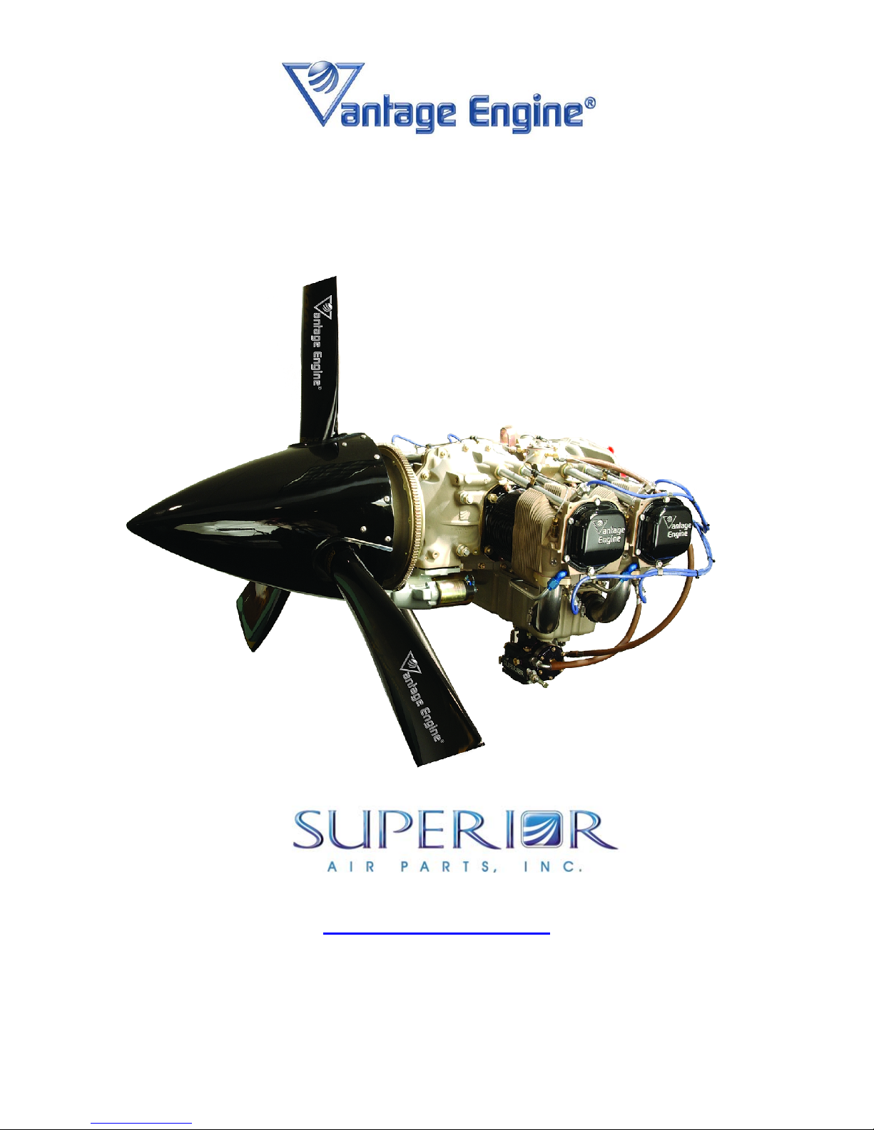
O-360 & IO-360 SERIES ENGINES
INSTALLATION & OPERATION MANUAL
621 South Royal Lane, Suite 100 / Coppell, TX 75019 / 800-277-5168
P/N SVIOM01 Revision A, March, 2004
www.superior-air-parts.com
FAA Approved
Page 2

Installation & Operation Manual
O-360 and IO-360 Series Engines
DISCLAIMER OF WARRANTIES AND LIMITATIONS OF LIABILITY
SUPERIOR'S EXPRESS WARRANTIES AND THE REMEDIES THEREUNDER ARE EXCLUSIVE AND
GIVEN IN PLACE OF (A) ALL OTHER WARRANTIES, EXPRESS, IMPLIED, OR STATUTORY,
WHETHER WRITTEN OR ORAL, INCLUDING, BUT NOT LIMITED TO, ANY WARRANTY OF
MERCHANTABILITY, FITNESS OR PARTICULAR PURPOSE, OR IMPLIED WARRANTY ARISING
FROM PERFORMANCE, COURSE OF DEALING OR USAGE OF TRADE AND (B) ALL OTHER
OBLIGATIONS, LIABILITIES, RIGHTS, CLAIMS OR REMEDIES, EXPRESS OR IMPLIED, ARISING BY
LAW OR OTHERWISE, INCLUDING BUT NOT LIMITED TO ANY RIGHT OR REMEDIES IN
CONTRACT, TORT, STRICT LIABILITY OR ARISING FROM SUPERIOR'S NEGLIGENCE, ACTUAL OR
IMPUTED.
SUPERIOR'S OBLIGATIONS AND PURCHASER'S REMEDIES UNDER SUPERIOR'S EXPRESS
WARRANTIES ARE LIMITED TO SUPERIOR'S CHOICE OF REFUND, REPAIR OR REPLACEMENT
ON AN EXCHANGE BASIS AND EXCLUDE LIABILITY FOR INCIDENTAL, SPECIAL,
CONSEQUENTIAL OR ANY OTHER DAMAGES, INCLUDING WITHOUT LIMITATION, ANY LIABILITY
OF CUSTOMER TO A THIRD PARTY OR FOR ECONOMIC LOSS, REPLACEMENT COST, COST OF
CAPITAL, LOST REVENUE, LOST PROFITS, OR LOSS OF USE OF OR DAMAGE TO AN AIRCRAFT,
ENGINE, COMPONENT OR OTHER PROPERTY AND IN NO EVENT WILL SUPERIOR'S LIABILITY
EXCEED THE ORIGINAL COST OF THE ENGINE OR ACCESSORY.
Written notice of any warranty claim must be submitted to Superior within thirty (30) days of a suspected
defect in material or workmanship and the engine, accessory or part must be made available for
Superior's inspection within thirty (30) days after the claim has been made. Superior reserves the right to
deny any claim not submitted in accordance with these requirements.
These LIMITED WARRANTIES are the only warranties offered by Superior. No agreement varying these
warranties or Superior's obligations under them will be binding on Superior unless made in writing by a
duly authorized representative of Superior.
Superior will not process or honor warranty claims on delinquent accounts.
© March 2004 Superior Air Parts Inc.
Page 3

Installation & Operation Manual
O-360 and IO-360 Series Engines
Table Of Contents
Chapter 1 Engine Description
Chapter 2 Airworthiness Limitations
Chapter 3 Aircraft / Engine Integration Considerations
Revision History
List Of Figures
List Of Tables
Introduction
About This Manual
Related Publications
Installation Approval Requirements
Obtaining Service Information
1. General Description
2. Continued Airworthiness
3. Model Designations
4. Engine Components General Description
5. Features And Operating Mechanisms
1. General
2. Induction System
3. Fuel System
4. Engine Cooling
5. Exhaust
6. Lubrication System
7. Propeller Attachment
8. Electrical System
9. Engine Controls
10. Engine Accessories
11. Engine Mounting
Page Number
i
ii
iii
iv
iv
iv
iv
v
1
1
1
3
13
1
1
4
7
9
12
15
16
18
20
22
Chapter 4 Engine Installation
1. General Instructions
2. Preparing Engine For Service
3. Installation of Engine
4. Instrumentation Connections
Chapter 5 Special Procedures
1. General Break In Procedures
2. Special Tools And Equipment
3. Break In Procedures
4. General Inspection Check
5. Daily Pre Flight Inspection
Chapter 6 Normal Operating Procedures
1. General
2. Engine Operation And Limits
3. Operation Instructions
© March 2004 Superior Air Parts Inc.
1
1
2
2
1
1
1
3
3
1
1
1
Page 4

Installation & Operation Manual
O-360 and IO-360 Series Engines
Table Of Contents (continued)
Chapter 7 Abnormal Operating Procedures
1. General
2. Engine Will Not Start
3. Rough Idling
4. Engine Not Able to Develop Full Power
5. Rough Engine Operation
6. Low Power and Engine Runs Rough
7. Low Oil Pressure On Engine Gage
8. High Oil Temperature
9. Excessive Oil Consumption
Chapter 8 Servicing Requirements
1. General
2. Lubricants
3. Fuels
4. Consumables
Chapter 9 Engine Preservation And Storage
1. Temporary Storage
2. Indefinite Storage
3. Inspection Procedures
4. Returning An Engine To Service After Storage
Appendix A O-360 Model Specification Data
Appendix B IO-360 Model Specification Data
1
2
2
3
3
3
4
4
4
1
1
2
2
1
2
2
3
© March 2004 Superior Air Parts Inc.
Page 5
Installation & Operation Manual
O-360 and IO-360 Series Engines
Manual Number SVIOM01
Revision History
Revision
Letter
A 03/29/04 Initial Release All
Effectiv
e
Date
Description Pages
Revised
It is the users responsibility to insure that this is the current revision of
this manual. Do not perform any operation, installation, maintenance,
or other procedure until confirming this manual is current.
© March 2004 Superior Air Parts Inc.
WARNING
i
Page 6

Installation & Operation Manual
O-360 and IO-360 Series Engines
List Of Figures
Figure
Number
1-1 Model Number Designation 1 1
1-2 O-360 Engine Front View 1 5
1-3 O-360 Engine Left Side View 1 6
1-4 O-360 Engine Top View 1 7
1-5 O-360 Engine Rear View 1 8
1-6 IO-360 Engine Front View 1 9
1-7 IO-360 Engine Left Side View 1 10
1-8 IO-360 Engine Top View 1 11
1-9 IO-360 Engine Rear View 1 12
3-1 Oil System Schematic 3 14
3-2 Ignition Wiring Diagram 3 17
3-3 Alternator Mounting Pad 3 21
3-4 #1 Dynafocal Mount Dimensions 3 23
3-5 #2 Dynafocal Mount Dimensions 3 23
3-6 Conical Mount Dimensions 3 24
3-7 Limit and Ultimate Engine Forces 3 26
3-8 Engine Mount Forcing Function for Engine Startup and Shutdown 3 27
3-9 Engine Mount Forcing Function for Steady State Conditions 3 27
Figure Description Chapter Page
© March 2004 Superior Air Parts Inc.
ii
Page 7

Installation & Operation Manual
O-360 and IO-360 Series Engines
List Of Tables
Table
Number
1-1 Manufacturer’s General Specifications 1 3
1-2 Manufacturer’s Physical Specifications 1 4
1-3 Views of the Engine 1 4
3-1 Accessory Drive Data 3 20
3-2 Lord Engine Mounts for Superior Vantage Engines 3 21
3-3 Limit and Ultimate Engine Mount Loads 3 25
4-1 Instrumentation Connections 4 2
6-1 Normal Starting Procedures 6 3
6-2 Starting A Flooded Engine 6 4
6-3 Ground Running / Fixed Wing Warm-Up 6 5
6-4 Ground Running / Rotorcraft Warm-Up 6 5
6-5 Fixed Wing - Pre-Takeoff Ground Check 6 6
6-6 Rotorcraft - Pre-Takeoff Ground Check 6 7
6-7 Fuel Mixture Leaning General Rules 6 8
6-8 Leaning with Exhaust Gas Temperature Gage 7 9
6-9 Leaning with Flowmeter 6 9
6-10 Leaning with Manual Mixture Control 6 9
6-11 Shut Down Procedure 6 9
7-1 Abnormal Operating Procedures 7 1
7-2 Engine Will Not Start 7 2
7-3 Rough Idling 7 2
7-4 Engine Not Able To Develop Full Power 7 3
7-5 Rough Engine Operation 7 3
7-6 Low Power & Engine Runs Rough 7 3
7-7 Low Oil Pressure On Engine Gage 7 4
7-8 High Oil Temperature 7 4
7-9 Excessive Oil Consumption 7 4
8-1 Oil Grades 8 1
8-2 Oil Sump Capacity 8 1
8-3 Minimum Octane Fuels 8 2
8-4 Consumables 8 2
Table Description Chapter Page
© March 2004 Superior Air Parts Inc.
iii
Page 8

Installation & Operation Manual
O-360 and IO-360 Series Engines
Introduction
About This Manual
This engine installation and operation manual is
provided as guidance for the installation and
installation design of a Superior Vantage Engine
to an airframe and to describe its’ operational
characteristics. Its purpose is to provide
technical information to aid in designing and
operating an effective engine installation so as
to achieve maximum performance while
providing for maximum service life.
Superior Air Parts has made clear and accurate
information available for those who maintain,
own and repair the Vantage O-360 and IO-360
Series Engines. Superior Air Parts values your
input regarding revisions and additional
information for our manuals. Please forward
your comments and input to:
Superior Air Parts
Attn. Engineering Department
621 South Royal Lane Suite 100
Coppell, Texas 75019
Related Publications
The following are related engine and accessory
publications.
O & IO-360 Maintenance Manual SVMM01
O & IO-360 Overhaul Manual SVOM01
O & O-360 Illustrated Parts Cat. SVIPC01
Unison Master Service Manual, F-1100
Precision RSA-5 Service Manual, 15-338
Precision MA-4-5 Manual, MSAHBK-1
Champion Aerospace Service Manual,
AV-6R
Installation Approval Requirements
The engine warranty for a Vantage Engine
installation is subject to the technical approval of
Superior. Upon approval of an installation
design, Superior will provide a letter that states
in part that the installation design is acceptable
and does not adversely effect the function of the
engine with respect to engine longevity while the
engine is operated in accordance with
recommended procedures.
Superior requires certain technical data
regarding the installation in order to determine
its acceptability for warranty purposes. This
data may include, but is not limited to drawings,
photographs and test data. Approval of the
installation for these purposes is limited to the
installation design furnished by the airframe
manufacturer to Superior. Modifications or
changes to the installation design requires a
new or amended letter of approval prior to the
warranty becoming effective for that design.
Approval of the installation by Superior as
described above is limited to engine warranty
issues only. It does not in any way indicate
approval of other aspects of the installation
design such as structural integrity and
manufacturability.
Superior Vantage Engines discussed in this
document must be installed and operated in
accordance with the limitations, conditions and
operating procedures described in this
document, the Model Specification Data and the
Installation and Operation Manual. They must
also be maintained in accordance with the
applicable Overhaul Manual and other
Instructions for Continued Airworthiness.
Superior accepts no responsibility for
airworthiness of any aircraft resulting from the
installation of the engine or associated
equipment.
© March 2004 Superior Air Parts Inc.
iv
Page 9

Installation & Operation Manual
O-360 and IO-360 Series Engines
Obtaining Service Information
All Vantage Series Engine manuals and service
information may be downloaded at:
www.superior-air-parts.com
All Vantage Series Engine manuals and service
information may also be purchased by
contacting:
Superior Air Parts
621 South Royal Lane, Suite 100
Coppell, Texas 75019
or call: 972-829-4600
Accessory Information may be obtained at:
www.championaerospace.com
www.unisonindustries.com
www.skytecair.com
www.precisionairmotive.com
www.aeroaccessories.com
© March 2004 Superior Air Parts Inc.
v
Page 10
Installation & Operation Manual
O-360 and IO-360 Series Engines
CHAPTER 1
Engine Description
1. GENERAL DESCRIPTION
Superior Vantage Engines are four-cylinder,
horizontally opposed, air-cooled, direct drive
powerplants incorporating a wet sump, bottom
mounted induction, bottom exhaust with either
carbureted or port injected fuel systems.
Provisions exist for both front and rear mounted
accessories. All engine components will be
referenced as they are installed in the airframe.
Therefore, the “front” of the engine is the
propeller end and the “rear” of the engine is the
accessory mounting drive area. The oil sump is
on the “bottom” of the engine and the cylinder
shroud tubes are on the “top”. The terms “left”
and “right” are defined as being viewed from the
rear of the engine looking toward the front.
Cylinder numbering is from the front to the rear
with odd numbered cylinders on the right side of
the engine. The direction of crankshaft rotation
is clockwise as viewed from the rear of the
engine looking forward unless otherwise
specified. Accessory drive rotation direction is
defined as viewed from the rear of the engine
looking forward.
2. CONTINUED AIRWORTHINESS
Vantage Engines discussed in this document
must be installed and operated in accordance
with the limitations, conditions and operating
procedures described in this document. They
must also be maintained in accordance with the
applicable Overhaul Manual and other
Instructions for Continued Airworthiness. The
engine’s time between overhaul (TBO) period is
initially defined as 1000 hours. A TBO extension
program is in process.
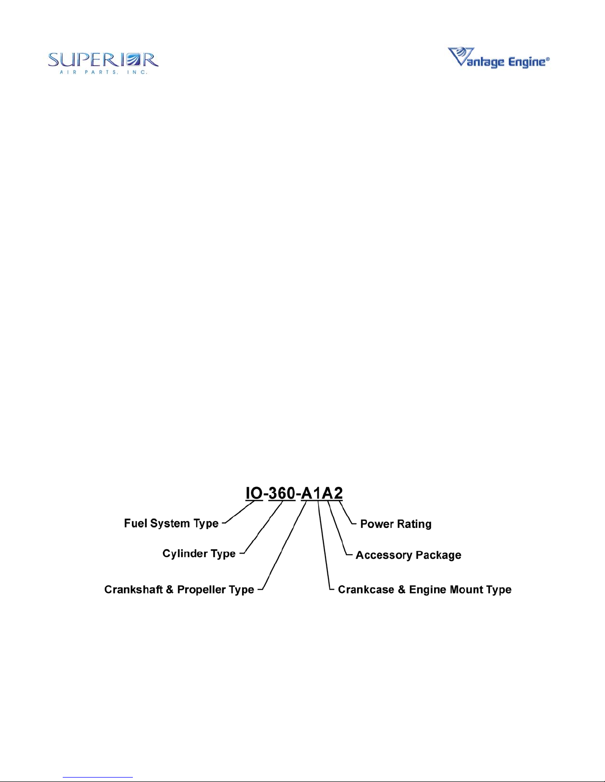
3. MODEL DESIGNATIONS
The model number designation is defined in a
way that the digits of the model number can
easily identify the basic configuration of the
engine as described in Figure 1-1.
Figure 1-1 • Model Number Designation
© March 2004 Superior Air Parts Inc. Chapter 1 • Engine Description
1
Page 11

Installation & Operation Manual
O-360 and IO-360 Series Engines
Fuel System Type
IO Denotes Port Fuel Injection System and “opposed cylinder” arrangement.
O Denotes a carbureted system and “opposed cylinder” arrangement.
Cylinder Type
360 Parallel valve cylinder, 361 cubic inches.
Model Suffix
1
A Fixed-Pitch, Thin-wall front main
B Constant-Speed, Thin-wall front main
2
4
Denotes detail engine configuration
st
Digit Crankshaft & Propeller Type
nd
Digit Crankcase & Engine Mount Type
1 #1 Dynafocal Mount
2 #2 Dynafocal Mount
3 Conical Mount
rd
3
Digit Accessory Package
Fuel System Ignition System
Carbureted Fuel Injected
A Unison Magnetos Precision Carburetor Precision Fuel Injection
th
Digit Power Rating: Piston Compression Ratio
1* - 2 8.5:1 180
*For Future Use
Cylinder Type
360
CR HP
© March 2004 Superior Air Parts Inc. Chapter 1 • Engine Description
2
Page 12
Installation & Operation Manual
O-360 and IO-360 Series Engines
4. ENGINE COMPONENTS GENERAL
DESCRIPTION
The O-360 and IO-360 series engines are air-cooled,
four cylinder, horizontally opposed, direct drive
engines. See Table 1-1 for Manufacturer’s General
Specifications.
A. The complete engine includes the following
components and assemblies:
1. Crankcase Assembly
2. Crankshaft Assembly
3. Camshaft Assembly
4. Valve Train Assembly
5. Cylinder Assemblies
6. Connecting Rod Assemblies
7. Oil Sump Assembly
8. Inter Cylinder Baffles
9. Starter
10. Lubrication System (includes oil filter)
11. Accessory Drive
12. Ignition System (includes spark plugs)
13. Fuel System
14. Starter Support Assembly
15. Oil Gage
16. Induction System
17. Accessories
Note:
Complete engine does not include
outer cylinder baffles, propeller governor,
and airframe to engine control cables,
attaching hardware, hose clamps, vacuum
pump, exhaust system, fittings or alternator.
B. Specifications
The manufacturer’s physical specifications
are listed in Table 1-2 are applicable to the
O-360 and IO-360 series engines. See
Model Specification Data (MSD) for more
specific information.
Table 1-1 • Manufacturer’s General Specifications
Model O-360 and IO-360
Rated Power Hp 180
Rated Speed, RPM RPM 2700
Bore, inches In 5.125
Stroke, inches In 4.375
Displacement cubic inches In3 361.0
Compression Ratio 8.5:1
Firing Order 1-3-2-4
Spark timing °BTDC 25
Propeller drive ratio 1:1
Propeller drive rotation
(viewed from rear)
© March 2004 Superior Air Parts Inc. Chapter 1 • Engine Description
Clockwise
3
Page 13

Installation & Operation Manual
O-360 and IO-360 Series Engines
Table 1-2 • Manufacturer’s Physical Specifications
Model
O-360 24.6 33.4 32.8 See MSD
IO-360 24.0 33.4 32.8 See MSD
Height
(In)
Width
(In)
Length
(In)
Weight
Table 1-3 • Views of the Engine
Engine View Figure Number Location
O-360 Engine Front View Figure 1-2 p. 5
O-360 Engine Left Side View Figure 1-3 p. 6
O-360 Engine Top View Figure 1-4 p. 7
O-360 Engine Rear View Figure 1-5 p. 8
IO-360 Engine Front View Figure 1-6 p. 9
IO-360 Engine Left Side View Figure 1-7 p. 10
IO-360 Engine Top View Figure 1-8 p. 11
IO-360 Engine Rear View Figure 1-9 p. 12
© March 2004 Superior Air Parts Inc. Chapter 1 • Engine Description
4
Page 14
Installation & Operation Manual
O-360 and IO-360 Series Engines
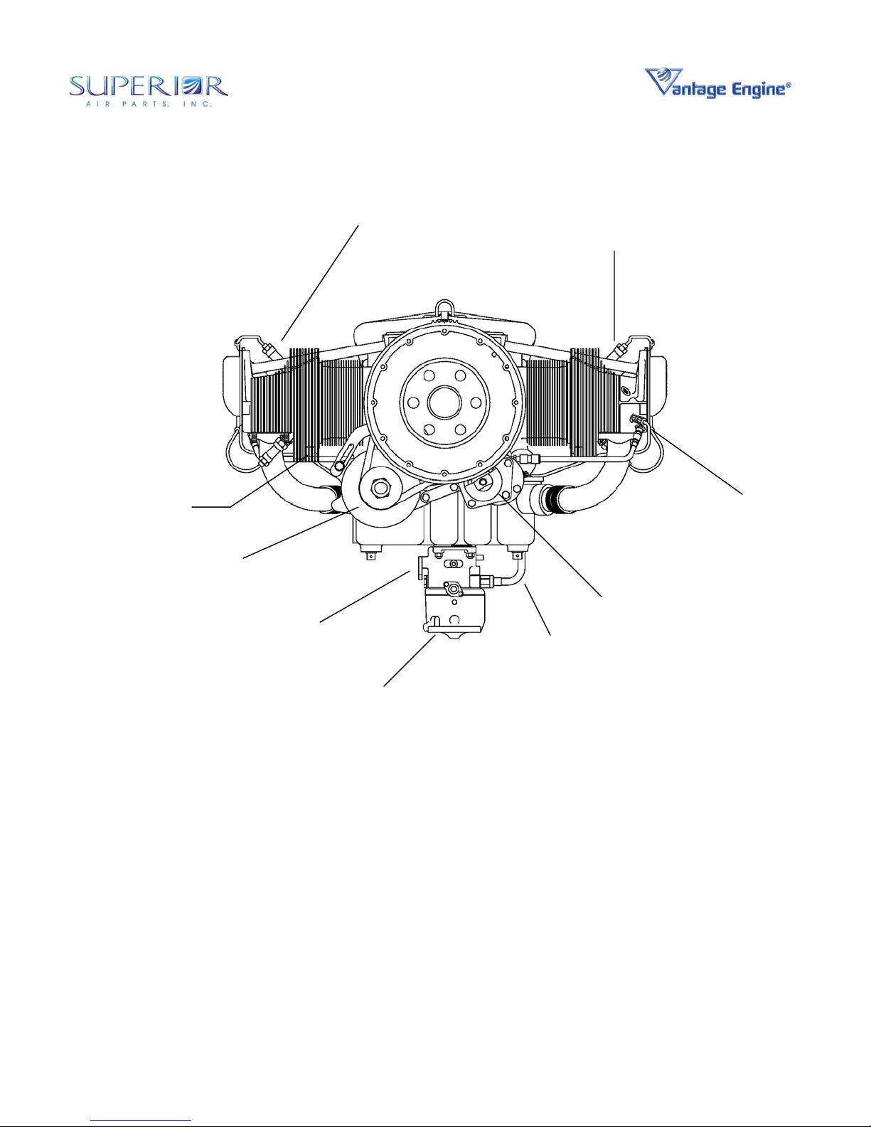
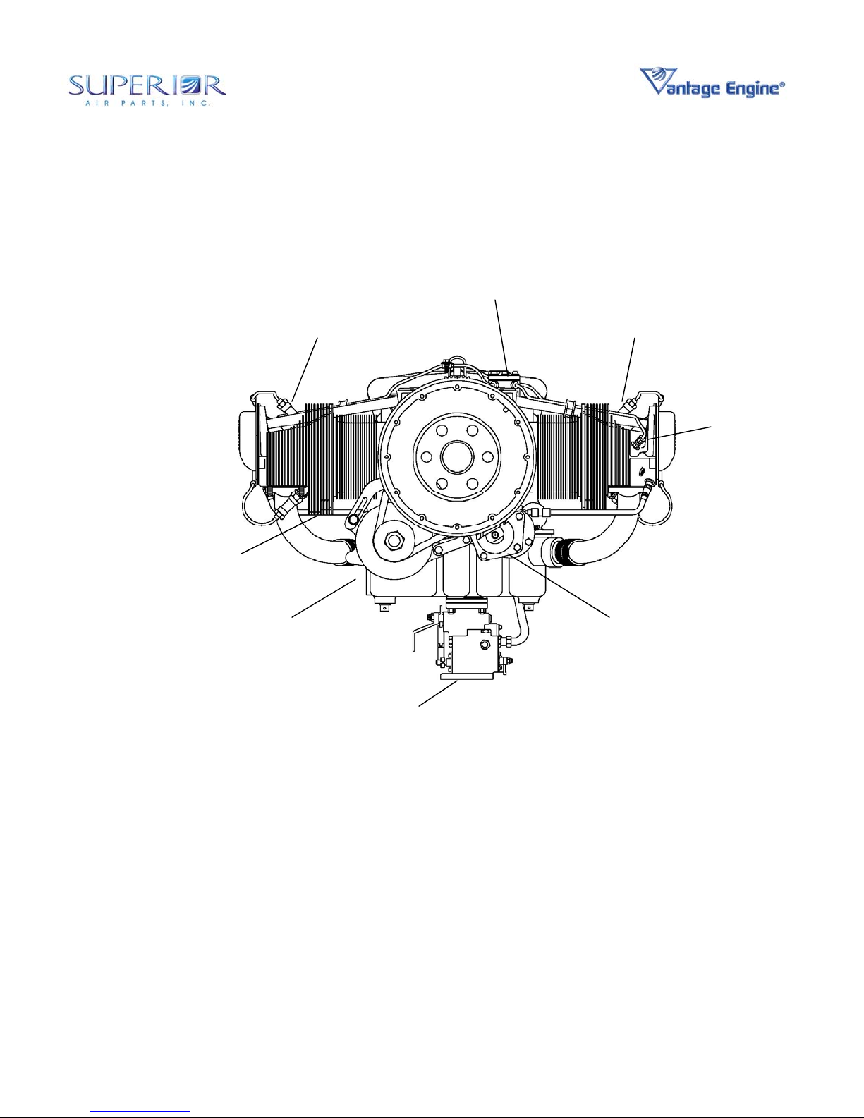
SPARK PLUG
SPARK PLUG
CHT PROBE LOCATION
(TYPICAL EACH HEAD)
ALTERNATOR & BELT NOT
PROVIDED WITH ENGINE
THROTTLE LEVER
FUEL LINE
CARBURETOR
Figure 1-2 • O-360 Engine Front View
STARTER
PRIMING
SYSTEM
© March 2004 Superior Air Parts Inc. Chapter 1 • Engine Description
5
Page 15
Installation & Operation Manual
O-360 and IO-360 Series Engines
CYLINDER
CRANKCASE
ASSEMBLY
ASSEMBLY
ACCESSORY
HOUSING
STARTER SUPPORT
ASSEMBLY
PRIMING
SYSTEM
STARTER
INDUCTION
SYSTEM
SPARK PLUG
OIL SUMP
ASSEMBLY
CARBURETOR
MIXTURE
LEVER
OIL FILTER
FUEL
PUMP
FUEL
LINE
HARNESS
MAGNETO
Figure 1-3 • O-360 Engine Left Side View
© March 2004 Superior Air Parts Inc. Chapter 1 • Engine Description
6
Page 16
Installation & Operation Manual
O-360 and IO-360 Series Engines
INTER-CYLINDER BAFFLE
SPARK PLUG
MAGNETO
MAGNETO
OIL FILTER
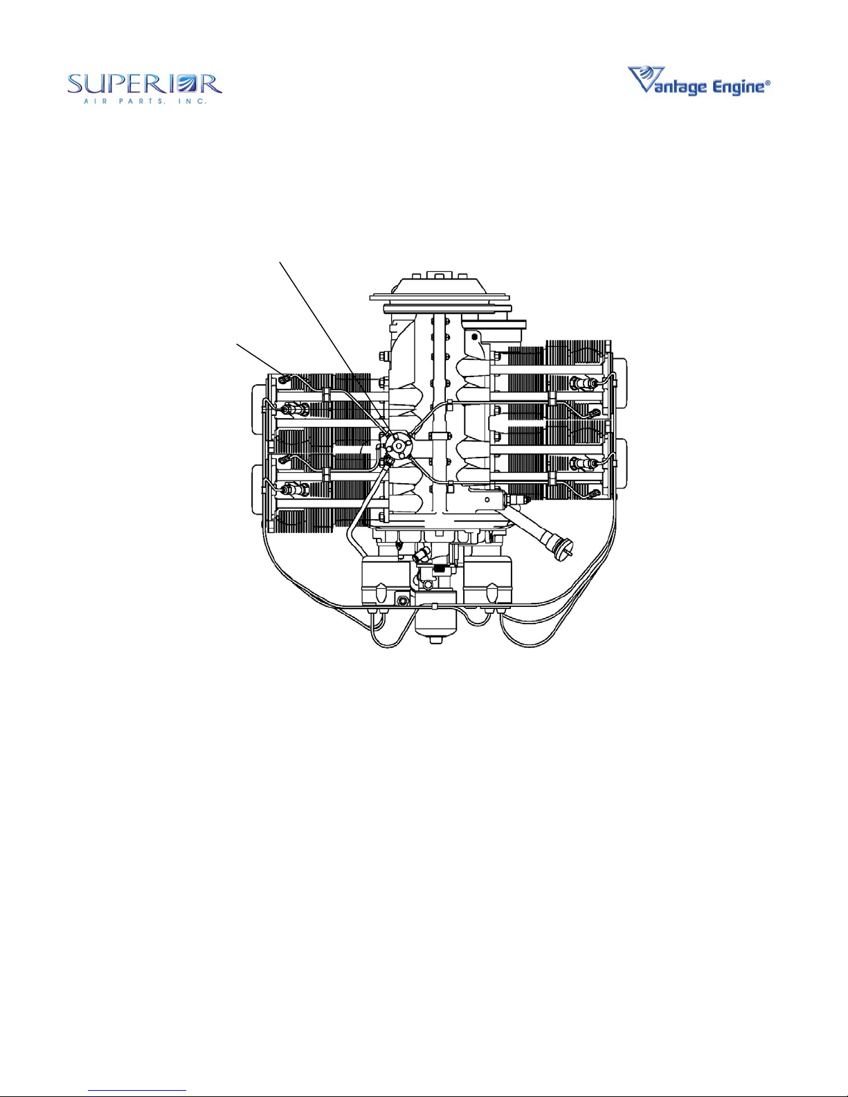
Figure 1-4 • O-360 Engine Top View
7
© March 2004 Superior Air Parts Inc. Chapter 1 • Engine Description
Page 17
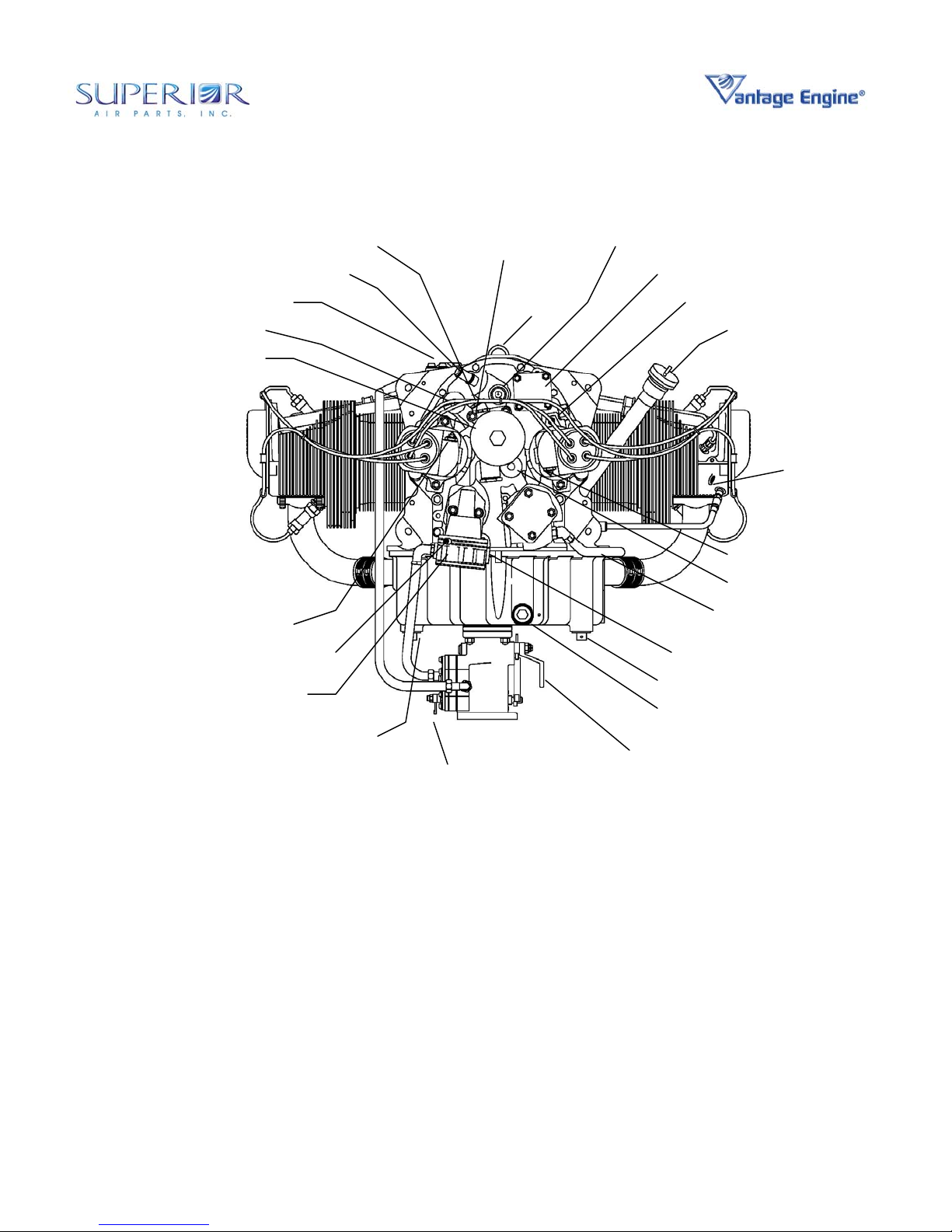
Installation & Operation Manual
O-360 and IO-360 Series Engines
OIL TEMP
CONNECTION
OIL RETURN FROM COOLER
OIL FILTER
GROUND OR “P-LEAD” TERMINAL
VENT LINE
CONNECTION
ALTERNATE OIL TO COOLER
BREATHER
FITTING
DIAPHRAGM
FUEL PUMP
FUEL LINE
FUEL MIXTURE
LEVER
EYE
BRACKET
TACHOMETER CONNECTION
VACUUM PUMP / ACCESSORY PAD
OIL DRAIN
PLUG
FUEL PUMP INLET
OIL SUCTION
SCREEN
THROTTLE
LEVER
OIL PRESSURE GAGE CONNECTION
OIL LEVEL TUBE & GAGE
MANIFOLD
PRESSURE
CONNECTION
GROUND OR “P-LEAD” TERMINAL
OIL SUPPLY TO COOLER
OIL LINE TO
PROPELLER
COMMON PRIMER
LINE SOURCE
Figure 1-5 • O-360 Engine Rear View
© March 2004 Superior Air Parts Inc. Chapter 1 • Engine Description
8
Page 18
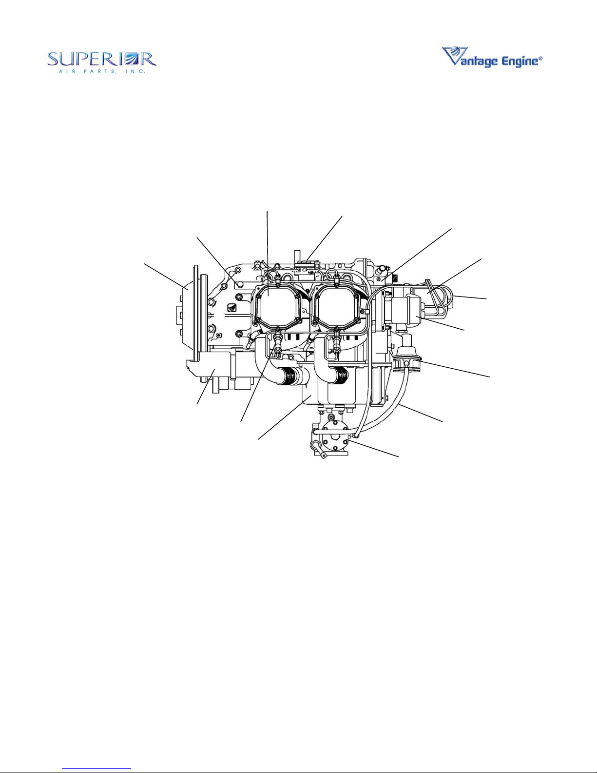
Installation & Operation Manual
O-360 and IO-360 Series Engines
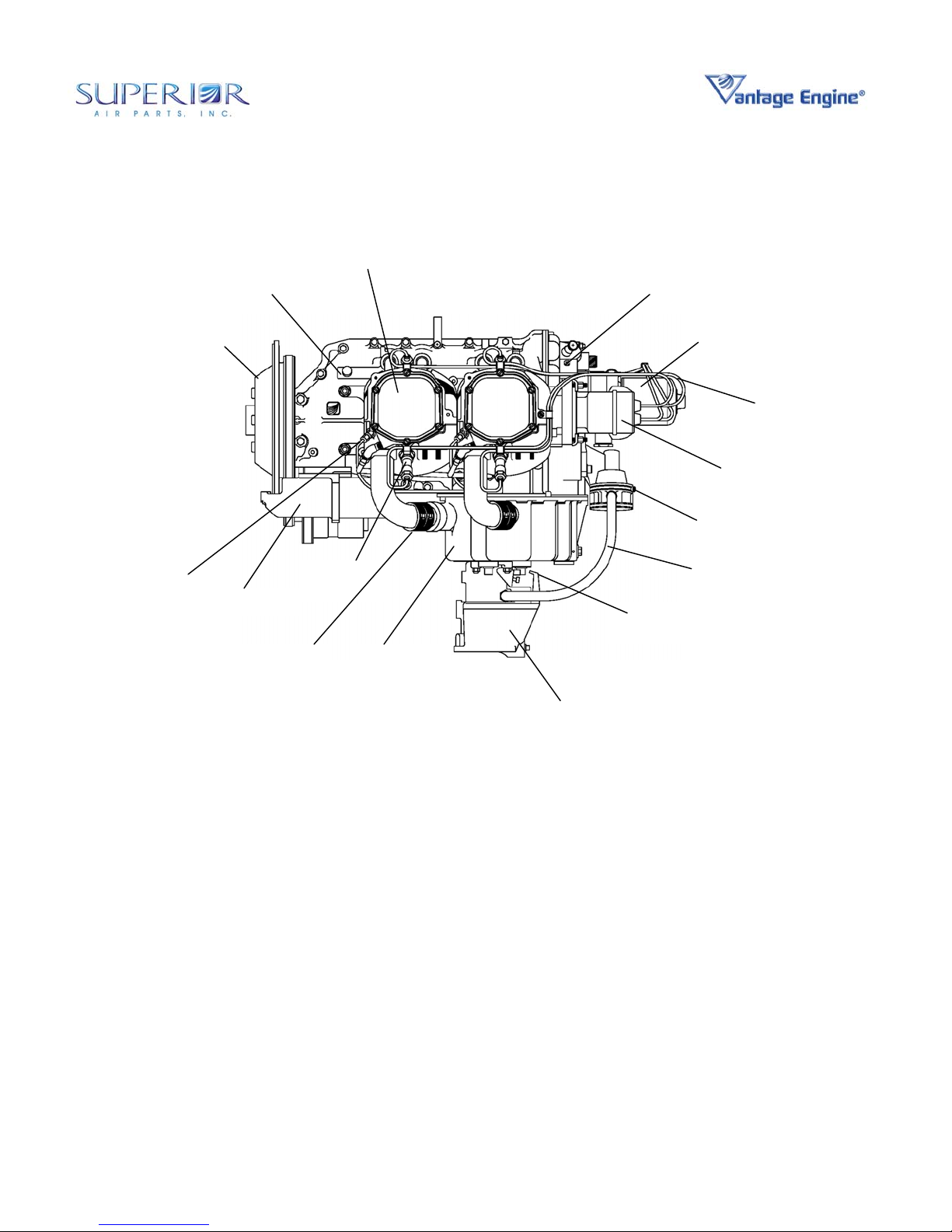
FUEL INJECTION
MANIFOLD
CHT PROBE LOCATION
(TYPICAL EACH HEAD)
NOT PROVIDED WITH ENGINE
SPARK PLUG
ALTERNATOR & BELT
FUEL INJECTION
SERVO
STARTER
SPARK PLUG
FUEL
INJECTOR
© March 2004 Superior Air Parts Inc. Chapter 1 • Engine Description
Figure 1-6 • IO-360 Engine Front View
9
Page 19
Installation & Operation Manual
O-360 and IO-360 Series Engines
STARTER SUPPORT
ASSEMBLY
CRANKCASE
ASSEMBLY
STARTER
SPARK PLUG
OIL SUMP
CYLINDER
ASSEMBLY
FUEL INJECTION
MANIFOLD
ACCESSORY
HOUSING
FUEL INJECTION
SERVO
MAGNETO
FUEL LINE
OIL FILTER
WIRING
HARNESS
FUEL PUMP
© March 2004 Superior Air Parts Inc. Chapter 1 • Engine Description
Figure 1- 7 • IO-360 Engine Left Side View
10
Page 20
Installation & Operation Manual
O-360 and IO-360 Series Engines
FUEL INJECTION
MANIFOLD
FUEL INJECTIOR
© March 2004 Superior Air Parts Inc. Chapter 1 • Engine Description
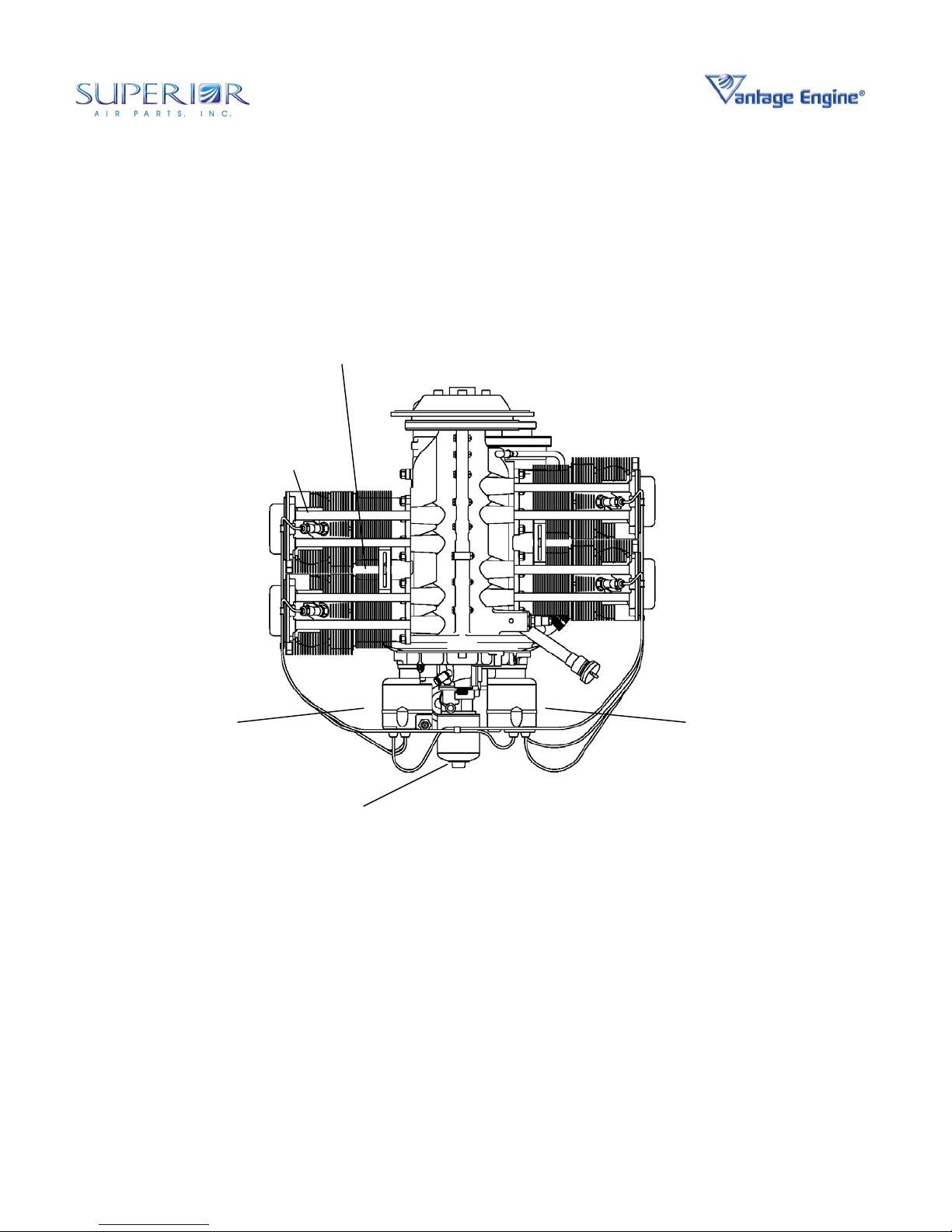
Figure 1- 8 • IO-360 Engine Top View
11
Page 21
Installation & Operation Manual
O-360 and IO-360 Series Engines
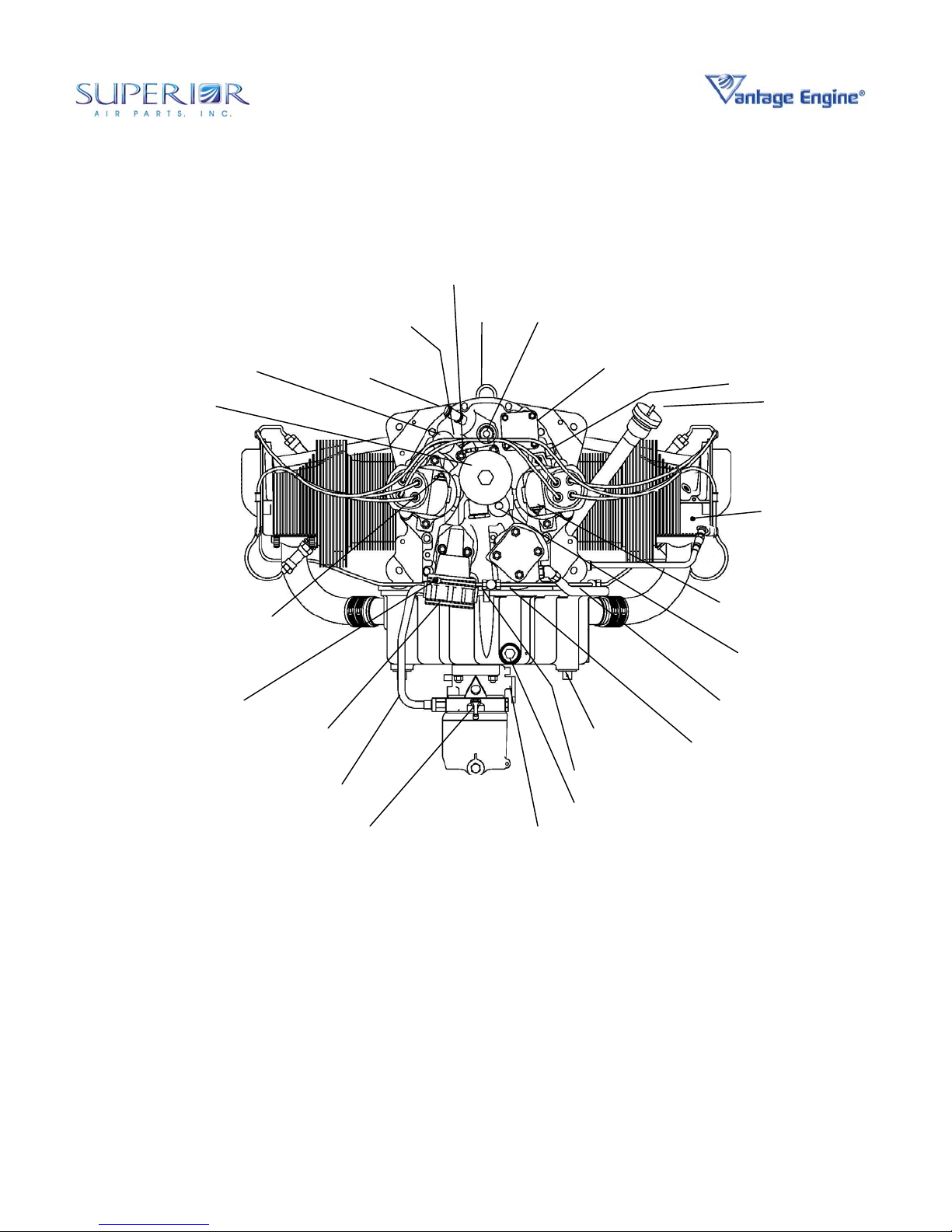
BREATHER FITTING
FUEL INJECTION MANIFOLD
OIL RETURN FROM COOLER
OIL FILTER
GROUND OR “P-LEAD” TERMINAL
VENT LINE CONNECTION
ALTERNATE OIL
TO COOLER
OIL TEMP
CONNECTION
EYE
BRACKET
TACHOMETER CONNECTION
VACCUM PUMP / ACCESSORY PAD
FUEL PUMP INLET
OIL PRESSURE GAGE CONNECTION
OIL LEVEL TUBE & GAGE
MANIFOLD
PRESSURE
CONNECTION
GROUND OR “P-LEAD” TERMINAL
OIL SUPPLY TO COOLER
OIL LINE TO
PROPELLER
DIAPHRAGM FUEL
PUMP
OIL DRAIN PLUG
MIXTURE CONTROL
LEVER
THROTTLE CONTROL
OIL DRAIN PLUG
OIL SUCTION
SCREEN
LEVER
Figure 1- 9 • IO-360 Engine Rear View
© March 2004 Superior Air Parts Inc. Chapter 1 • Engine Description
12
Page 22

Installation & Operation Manual
O-360 and IO-360 Series Engines
5. FEATURES AND OPERATING
MECHANISMS
Crankshaft - The crankshaft is made from
aerospace grade SAE 4340 Vacuum-Arc-Remelt
(V.A.R.) steel per AMS 6414. All bearing journal
surfaces are nitrided.
Connecting Rods - The connecting rods are
made from aerospace grade SAE 8740 forgings
per AMS 6325. They have replaceable bearing
inserts in the crankshaft ends and bronze
bushings in the piston ends. The bearing caps
on the crankshaft ends are retained by two bolts
with self locking nuts per cap. Caps are tongue
and groove type for improved alignment and
rigidity.
Camshaft - Valve Operating Mechanism - The
camshaft is located above and parallel to the
crankshaft. The camshaft actuates hydraulic
lifters that operate the valves through push rods
and valve rockers.
Crankcase - The crankcase is made from
aerospace grade AA C355-T71 stabilized
structural aluminum alloy per AMS 4214. The
assembly consists of two reinforced aluminum
alloy castings fastened together by means of
studs, bolts, and nuts. The main bearing bores
are machined for use with precision type main
bearing inserts.
Accessory Housing - The accessory housing is
made from an aluminum casting and is fastened
to the rear of the crankcase and the top rear of
the sump.
Oil Sump - The sump incorporates an oil drain
plug, oil suction screen, mounting pad for
carburetor or fuel injector, the intake riser, and
intake pipe connections.
Cylinders - Millennium
exclusively. These air-cooled cylinders are
manufactured by screwing and shrinking the two
major parts, head and barrel, together. The
heads are made from AMS 4220 aluminum alloy
casting material. All barrels are made from
forgings produced to AMS 6382 forging
specifications. They are internally choked and
honed to allow optimal operating conditions for
the rings and pistons at operating temperatures.
© March 2004 Superior Air Parts Inc. Chapter 1 • Engine Description
®
Cylinders are used
Pistons - The pistons are made from an
aluminum alloy. The piston pin is a full floating
type with a plug located in each end of the pin.
The piston is a 3-ring type with 2 compression
rings and 1 oil control ring.
Cooling System – Superior Vantage Engines
are designed to be air-cooled. Baffles are
provided to build up air pressure and force the
air between the cylinder fins. The air is
exhausted to the atmosphere through the rear of
the cowling.
Induction System - The distribution of the air to
each cylinder is through the center zone of the
induction system. This is integral with the oil
sump.
Fuel Systems
Carbureted
are equipped with a float type carburetor The
MA-4-5 carburetors are of the single barrel float
type equipped with a manual mixture control and
an idle cut-off.
Fuel Injected
equipped with a direct cylinder injected RSA-5
fuel injector. The fuel injection system
schedules fuel flow in proportion to airflow. Fuel
vaporization takes place at the intake ports. The
RSA fuel injection system is based on the
principle of measuring airflow and using the air
pressure in a stem type regulator, converting the
air pressure into a fuel pressure. The fuel
pressure (fuel pressure differential), when
applied across the fuel metering section (jetting
system), makes fuel flow proportional to airflow.
Lubrication System - The full pressure wet
sump lubrication system is supplied by a gear
type pump. It is contained within the accessory
housing.
Priming System - A manual primer system is
provided on all engines using a carburetor. Fuel
injected engines do not require a manual
priming system, relying instead on the fuel
injectors for priming.
Ignition System - Dual ignition is furnished by
two Unison magnetos with two spark plugs per
cylinder. Each magneto is equipped with
impulse coupling for improved starting.
13
- Superior Air Parts O-360 engines
- IO-360 series engines are
Page 23

Installation & Operation Manual
O-360 and IO-360 Series Engines
CHAPTER 2
Airworthiness Limitations
The Airworthiness Limitations Section is F.A.A.
approved and specifies maintenance required
under sections 43.16 and 91.403 of the Federal
Aviation Regulations unless an alternate
program has been FAA approved. This section
is part of the type design of the O-360 and IO360 engine series pursuant to certification
requirements of the Federal Aviation
Regulations.
1. MANDATORY REPLACEMENT TIME
Subject to additional information contained in
F.A.A. Approved Mandatory Service Bulletins
issued after the date of certification, the O-360
and IO-360 engine series do not contain any
components having mandatory replacement
times required for type certification.
2. MANDATORY INSPECTION INTERVALS
Subject to additional information contained in
F.A.A. Approved Mandatory Service Bulletins
issued after the date of certification, the O-360
and IO-360 engine series do not contain any
components having mandatory inspection
intervals.
3. OTHER MANDATORY INTERVALS OR
PROCEDURES
Subject to additional information contained in
F.A.A. Approved Mandatory Service Bulletins
issued after the date of certification, the O-360
and IO-360 engine series do not have any
inspection-related or replacement time-related
procedures required for type certification.
4. DISTRIBUTION OF CHANGES TO
AIRWORTHINESS
Changes to this Airworthiness Limitations
Chapter constitute changes to the type design of
the O-360 and IO-360 engine series and require
F.A.A. approval pursuant to Federal Aviation
Regulations. Such changes will be published in
F.A.A. Approved Mandatory Service Bulletins.
Superior Vantage Engine Service Bulletins may
be obtained by writing to:
Superior Air Parts
621 South Royal Lane, Suite 100
Coppell, Texas 75019
or call: 972-829-4600
or on the web at www.superior-air-parts.com
© March 2004 Superior Air Parts Inc. Chapter 2 • Airworthiness Limitations
1
Page 24

Installation & Operation Manual
O-360 and IO-360 Series Engines
CHAPTER 3
Aircraft / Engine Integration Considerations
1. GENERAL
The following sections in this chapter include a
discussion of design practices to be considered
during the integration of a Superior Vantage
engine with an airframe and propeller. These
discussions should be used IN ADDITION TO
the applicable requirements of the FARs.
Superior requires that proper functioning of the
system designs outlined in this chapter be
proven prior to activation of the warranty.
Proper functioning of the installation design shall
be proven by technical data such as test data,
photographs, drawings and engineering
calculations. Superior Air Parts Engineering
Department will provide guidance regarding the
specifics of these requirements as appropriate to
the installation and on a case-by-case basis.
Throughout this chapter reference is made to
data contained in the Model Specification Data.
These documents are engine series specific and
are contained in Appendices of this manual.
Refer to the appropriate Model Specification
Data for your engine model when consulting this
data.
2. INDUCTION SYSTEM
The induction system design can significantly
effect both performance and longevity of an
aircraft engine installation. In addition to more
obvious issues such as air filtration, seemingly
insignificant design features can cause
restrictions or other airflow disturbances
resulting in flow loss or improper function of the
fuel metering system. Induction systems which
yield excessive intake air temperatures can
promote engine detonation.
A. General Induction System Design
It is important that the induction system of
naturally aspirated engines such as the Superior
1 Chapter 3 • Aircraft / Engine
© March 2004 Superior Air Parts Inc. Integration Considerations
Vantage Series be capable of supplying clean,
filtered, cool intake air to the engine at the
maximum required flowrate and with maximum
attainable pressure. The term “maximum
attainable pressure” as used here refers to an
air source that provides maximum intake air
pressure, (including ram air effects) while
minimizing restrictions and flow losses. A
reduction in flowrate or total pressure, or
increased temperature can cause power loss,
reduced service ceiling and increased possibility
of detonation during high power requirements.
Properly engineered intake systems for naturally
aspirated engines should result in total intake air
pressures that are greater than ambient air
pressure. For example, air pressure in the intake
system can be raised by
directing the face of the air pickup into the
relative wind of the aircraft. Further, by locating
the air pickup within the propeller diameter, ram
air effects can be increased. Care should be
taken to position the air pickup as far as possible
away from the propeller axis (but within the
“propeller envelope”) so as to take advantage of
the increased air velocities at the outer areas of
the prop. Care should also be given to prevent
“blanking” of the intake air pickup by the prop
blade. Increasing the size of the air pickup,
particularly in the direction perpendicular to the
blade axis, can help reduce this potential. Care
should also be given to designing an air pickup
that maintains maximum frontal area during
periods of high aircraft angle of attack.
Typically, maximum power is required during
flight conditions having high angle of attack and
reductions in airflow will restrict maximum power
capability.
The intake air system should be designed to
minimize pressure and flow losses. Sharp
elbows and abrupt duct expansions or
contractions all contribute to system losses.
Changes in duct sizing should be accompanied
by tapered transitions to minimize these losses.
Duct losses are a function of air velocity and can
Page 25

Installation & Operation Manual
O-360 and IO-360 Series Engines
be significantly reduced by increasing duct size
and thereby reducing the air velocity.
Utilizing ducts with circular cross-sections or
“square” cross-sections with the highest possible
aspect ratio can also reduce duct losses.
Turning vanes can be used to reduce losses in
sharp corners when necessary.
The state of the airflow as it enters the
carburetor or fuel injector servo body is critical to
effective and efficient fuel mixing. Both
carburetor and fuel injector servo bodies sense
mass airflow and introduce fuel based on that
measurement. If the airflow is turbulent during
this process, inaccurate airflow sensing can
occur resulting in improper fuel flow. Turbulence
of the intake air in a carbureted system will also
promote poor fuel / air mixing and large cylinder
to cylinder mixture variations. The
consequences of these conditions can be as
simple as reduced power or as great as incylinder detonation.
Care should also be given to the placement of
the intake system with respect to hot areas such
as exhaust pipes and other engine components.
Cooler intake air results in better power output
and greater service ceilings. Intake systems
that allow heating of the air reduce available
engine power and can reduce service ceilings.
B. Intake Air Requirements and Filtration
The intake air and filtration system must be
designed for both effective and efficient filtering
with minimal flow loss. Studies have shown that
particulates greater than about 10 microns in
size are particularly harmful to engines;
therefore the filtration system should be selected
accordingly. Filter manufacturers can provide
data regarding effectiveness, efficiency and
capacity of their products including the effect of
particulate size. Guidance regarding overall filter
size, based on filter capacity, can be obtained
from the filter manufacturer.
The size of the air filter must also consider the
total engine airflow requirements and the
maximum air velocity requirements of the filter.
In general, filters are more effective for lower air
velocities but practical considerations must be
made based on space available. Intake air flow
requirements of a Superior Vantage Engine are
defined in Figure 1 of the Model Specification
2 Chapter 3 • Aircraft / Engine
© March 2004 Superior Air Parts Inc. Integration Considerations
Data. It is recommended that the filter be sized
to provide a minimum of 150% of this flow to
minimize pressure drop for both clean and dirty
filters.
C. Carburetor Heat
Due to the cooling effects of both fuel
vaporization and airflow through the venturi,
carburetor ice can form with outdoor air
temperatures as high as 100°F. Therefore, it is
necessary to provide a mechanism to introduce
heat to the intake airstream, downstream of the
air filter, to prevent this condition and to correct it
if icing were to occur. This mechanism also
serves the purpose of an alternate air source
should the filter become unexpectedly blocked
due to ice or debris. The minimum temperature
rise required of the carb heat mechanism is
specified in the FARs.
The design of the carb heat system should, in
general, follow the same guidelines as the
induction air system to minimize pressure loss
and turbulence. For example the flow area
should be as large as possible to reduce air
velocity and therefore flow losses. Relatively
slow-moving air across a heat source will also
experience a higher temperature rise than
faster-moving air over the same heat source.
Good practice suggests that the carb heat duct
should be at least 75% the size of the carburetor
inlet.
The air source for the carb heat mechanism
should be from a source other than the
“standard” filtered intake air. It is common for
the carb heat air to be drawn from within the
lower cowl area. It is also conventional to omit
the use of a traditional air filter at the carb heat
source for several reasons includ ing preventing
the risk of filter blockage for alternate air.
However, it is good practice to include a course
screen to prevent ingestion of “large” foreign
objects.
The carb heat air is normally introduced to the
induction airstream by means of a mixing box.
The mixing box includes a baffle door that is
manually actuated by the pilot and governs the
amount of filtered induction air or carb heat air
that is supplied to the carburetor.
Page 26

Installation & Operation Manual
O-360 and IO-360 Series Engines
It is important that the design of the mixing box
and damper door minimize pressure drop and
turbulence of either filtered intake air or carb
heat air. Some turbulence is unavoidable in this
transition; however it is recommended that a
“straight” section of duct be available after the
transition to smooth the airflow. If possible, this
section should be a length equivalent to 10
diameters. If this length is not possible due to
geometry constraints then appropriate steps
should be taken to straighten the flow. In either
case, thorough testing should be performed to
verify that both intake airflow and carb heat
airflow is free of excessive pressure drop and
turbulence to the extent that they do not degrade
engine performance.
Good practice also dictates that the mixing box
damper door be spring actuated to partially
actuate automatically in the event of unexpected
air filter blockage due to ice or debris. Care
should be taken in the design of this mechanism
to prevent “flutter” of the damper door during
normal operation in either the filtered air or carb
heat mode. The mechanism should also be
designed to prevent unintended use of carb heat
during the filtered air mode, including the effects
of “normal” filter blockage. That is, the automatic
spring mechanism should not be designed to be
so sensitive that normal pressure drop due to
filter use over time would cause carb heat air to
be introduced.
D. Alternate Air Source
Fuel injected engines introduce fuel to the
induction air at the heated cylinder port and do
not present the same concerns regarding
induction icing as the carbureted systems.
However, provisions are required to provide an
alternate induction air source for fuel injected
systems to prevent engine stoppage in the event
of filter blockage due to ice or debris. As with
the design of the carb heat mechanism, this is
conventionally done by drawing air from the
heated lower cowl area and introducing this air
downstream from the intake air filter. Although it
is acceptable to use a mixing box device with
flapper door mechanism as with the carb heat
apparatus, this is not necessary. Where the
carb heat mixing box must be designed so as to
select between the two air sources, the alternate
air source for fuel injected engines is simply the
availability of alternate air. Therefore, it is not
necessary to “block off” the normal filtered air
source.
Like the carb heat mechanism, the alternate air
source should be designed to minimize both flow
losses and turbulence. An entrance area at
least 75% of the fuel injector servo area is
recommended as well as provisions to
straighten the flow after introduction to the intake
air duct. A screen to prevent ingestion of “large”
foreign objects may be necessary.
The alternate air source mechanism should be
manually controllable by the pilot. As with the
carb heat mechanism, it is advised that the
alternate air source be spring actuated so it will
partially actuate automatically in the event of
unexpected air filter blockage due to ice or
debris. The mechanism should be designed to
preclude flutter and unintended operation during
the filtered air mode, including the effects of
“normal” filter blockage. The automatic spring
mechanism should not be designed to be so
sensitive that normal pressure drop due to filter
use over time would cause carb heat air to be
introduced.
E. Backfire Tolerance
The induction system, carb heat mechanism and
alternate air source must be designed to
withstand “normal” induction backfire events
without structural failure or fire.
3 Chapter 3 • Aircraft / Engine
© March 2004 Superior Air Parts Inc. Integration Considerations
Page 27

Installation & Operation Manual
O-360 and IO-360 Series Engines
3. FUEL SYSTEM
The fuel system design can significantly effect
both performance and longevity of an aircraft
engine installation. In addition to the obvious
performance aspects, fuel systems that limit the
fuel supply can promote engine detonation and
vapor lock. Un-damped and extreme pressure
pulsations can cause malfunction of the fuel
metering systems.
A. Fuel System Requirements and Filtration
Superior Vantage Engines are supplied with
positive displacement fuel pumps that are
directly driven by the engine. These pumps are
designed to provide the appropriate flow and
pressure to the fuel metering devices according
to their requirements. The aircraft fuel system
should be capable of providing at least twice the
maximum engine fuel flow requirements to
minimize the potential for vapor formation. The
fuel flow requirements are defined in Table 1 of
the Model Specification Data.
The flow of fuel must be vapor free, water free
and filtered to be free of foreign objects or
debris. The foreign object filter requirements are
defined in Table 2 of the Model Specification
Data.
B. General Fuel System Design
The aircraft fuel system should be designed so
flow restrictions do not occur in the piping
system. Flow restrictions in this context refer to
system conditions such as sharp radius bends,
abrupt changes in pipe diameter (larger or
smaller), tee and other fittings, valves, etc. In
addition to limiting maximum fuel flow, flow
restrictions increase the potential for vapor
formation. Vapor formation, if extreme can
cause engine stoppage due to lack of fuel.
Vapor formation in a minimal degree can cause
lean operation of the engine that can lead to
improper operation, service ceiling restrictions or
engine detonation under certain conditions.
Note:
unleaded fuel, do not use 90° fittings. Instead,
use large radius bends to reduce the likelihood
of vapor lock. Also, try to locate the fuel boost
pump as close to the fuel tank as possible.
Periodically inspect non-metallic fuel system
components for degradation.
Aircraft boost pumps (non-engine driven) may
be used to supplement fuel flow to the engine
driven fuel pump, prevent vapor lock and aid in
priming of fuel injected systems. The maximum
inlet pressure allowable at the engine driven fuel
pump is defined in Table 3 of the Model
Specification Data. Although the use of aircraft
boost pumps are not required for engine
operation (other than priming of fuel injection
systems), Superior Air Parts recommends their
use as a backup to the engine driven fuel pump
and as an aid in preventing vapor lock,
particularly when using motor gasoline. The fuel
system should be designed such that the
minimum acceptable fuel pressure is available to
the engine driven fuel pump at all times without
the use of an aircraft boost pump. The minimum
acceptable fuel pressure is defined in Table 3 of
the Model Specification Data. In addition, the
fuel system should be capable of providing at
least 150% the maximum required flow of fuel to
the engine driven fuel pump without the need for
an aircraft boost pump. (See Table 1 of the
Model Specification Data.)
Fuel tanks should be vented to the atmosphere
to prevent vacuum formation in the fuel tanks. If
un-vented, the pressure in the fuel tank (as fuel
is consumed) can reduce to the point that the
pressure available at the pump inlet is below the
cavitation limit of the pump. In this case,
cavitation can occur and engine stoppage due to
fuel starvation is possible.
Superior Air Parts recommends the use of fuel
flow meters as an aid to the pilot for proper
engine management. Two types of fuel flow
meters are available for use in such systems;
those that indicate flow based upon sensed
pressure and those that sense flow directly.
When running fuel lines for use with
4 Chapter 3 • Aircraft / Engine
© March 2004 Superior Air Parts Inc. Integration Considerations
Page 28

Installation & Operation Manual
O-360 and IO-360 Series Engines
Fuel flow meters that indicate flows based upon
fuel system pressure can be less accurate than
those that sense flow directly in times when
abnormalities occur. For example, dirty fuel
injectors or carburetor float malfunctions can
cause increases or decreases to system
pressure that would result in improper fuel flow
indications for pressure-based flow meters. For
this reason, Superior Air Parts recommends the
use of direct sensing flow meters such as vane
or turbine styles.
C. Carburetors
Carburetors used on Superior Vantage Engines
are conventional single barrel float type systems
with updraft induction and are equipped with
manual throttle and mixture controls. In the full
lean position, the manual mixture control serves
as an idle cutoff control. The carburetor requires
a low-pressure engine driven fuel pump
(supplied).
Superior Vantage Carbureted Engines require a
priming system. The engines are supplied with
manual primer lines installed to the #1, #2 and
#4 cylinder inlet ports and plumbing to feed from
a common primer source. The aircraft priming
system should be attached to this common
primer source.
The carburetor system is part of the Superior
Vantage Engine and therefore certified as part of
the engine. No one may make significant
changes to either flow settings or mechanical
linkages without prior approval by Superior.
Proper functioning and mixture settings of the
carburetor system must be made in flight and
ground idle tests. These tests should include all
envisioned flight attitudes and conditions as well
as ground idle temperature variations. In
addition to performance characteristics, exhaust
gas and cylinder head temperatures must be
monitored during these tests as a means of
verifying the correctness of the carburetor
system settings.
D. Fuel Injection Systems – Port Type
Fuel injector systems used on Superior Vantage
Engines are direct port injection systems with a
fuel-metering servo at the entrance to the intake
manifold. The fuel-metering servo is equipped
with manual throttle and mixture controls. In the
full lean position, the manual mixture control
serves as an idle cutoff control. The fuel
injection system requires a high-pressure engine
driven fuel pump (supplied).
Superior Vantage Fuel Injected Engines do not
require a separate priming system. Priming is
accomplished by operating an aircraft boost
pump with the manual mixture control in the fullrich position. After priming, the manual mixture
control should be moved to the idle cutoff
position for engine start and then moved back to
full rich after the engine has started.
Proper functioning and mixture settings of the
fuel injection system must be made in flight and
ground idle tests. These tests should include all
envisioned flight attitudes and conditions as well
as ground idle temperature variations. In
addition to performance characteristics, exhaust
gas and cylinder head temperatures must be
monitored during these tests as a means of
verifying the correctness of the fuel injection
system settings.
5 Chapter 3 • Aircraft / Engine
© March 2004 Superior Air Parts Inc. Integration Considerations
Page 29

Installation & Operation Manual
O-360 and IO-360 Series Engines
E. Fuels
Superior Vantage Engines are certified for
100LL Avgas per ASTM D910, 91/98 (lead
optional) Avgas per ASTM D910 and Motor
Gasoline with a minimum antiknock index
(R+M/2 method) of 91 per ASTM D4814. Higher
octane fuel improves the detonation margin
during high power and/or hot operation. When
operating on unleaded fuel, Superior
recommends using fresh, premium auto fuel
available at a major brand, reputable gas
station.
The use of auto fuel blended with alcohol
(ethanol) is forbidden. Winter oxygenated
ethanol fuel blends, or reformulated gasoline are
typically most available during the colder months
for smog reduction. Ethanol (alcohol) mixed
with unleaded fuel can cause vapor lock,
carburetor ice, reduction in range, carburetor
problems, and damage to the fuel system. The
use of an alcohol (and water) tester is
recommended. Acceptable gasoline is specified
per ASTM D-4814 (European EN228), again
without alcohol.
When running fuel lines for an airplane intended
for unleaded auto fuel operation, it is very
important to address issues that can reduce the
likelihood of vapor lock. For example, replace
90° fittings with smooth tubing bent to a larger
radius and do not use expansion or contraction
fittings. Locate the fuel boost pump as close to
the fuel tank as possible. Non-metallic fuel
system components should be manufactured
from materials that are known to be compatible
with auto fuels.
6 Chapter 3 • Aircraft / Engine
© March 2004 Superior Air Parts Inc. Integration Considerations
Page 30

Installation & Operation Manual
O-360 and IO-360 Series Engines
4. ENGINE COOLING
The engine cooling system design can
significantly effect both performance and
longevity of an aircraft engine installation. High
engine temperatures can result in loss of power,
fuel vapor lock, and can promote accelerated
wear and even engine detonation.
A. General Cooling System Design
The Superior Vantage Engine is a horizontally
opposed, air-cooled design. As such, all heat is
removed from the engine either by airflow over
the cylinders and crankcase or through an air-tooil lubricant heat exchanger. The horizontally
opposed cylinder arrangement is a space
efficient design that allows maximum cooling
airflow with minimum drag.
In general, air cooling of the engine heads and
crankcase occurs by directed airflow over those
components. Air is commonly received into the
cowl in a plenum above the engine and directed
downward between the cylinder and barrel fins
to a volume within the lower cowl.
The cooling air normally exits the lower cowl
through the exhaust tailpipe exit area. Airflow
over the engine is governed by the pressure
differential between the upper cowl and lower
cowl areas. In high performance installations
cowl flaps may be added to increase the cooling
airflow.
Superior Vantage Engines are provided with
inter-cylinder metal baffles to aid in the control of
cooling airflow over the cylinders and barrels. In
addition, the installation design must include
baffles that attach to the engine and provide a
seal to the interior of the cowl thus creating a
separation between the upper and lower cowl
volumes. This is typically done primarily with
metal components for stiffness against the ram
air pressure with flexible rubber seals to conform
to the contours of the upper cowl and to allow for
relative movement between the engine and
cowl.
The lubricating oil for Superior Vantage Engines
must be cooled by means of an air-to-fluid heat
exchanger. Typically, this heat exchanger is
mounted to the engine mount structure and
fastened to a rear engine baffle(s), open to the
upper plenum and facing the nose of the cowl.
In this way, ram effect of the cooling air entering
the upper plenum can be utilized to increase the
airflow through the heat exchanger.
B. Airside Heat Rejection
Airside heat rejection, that is heat rejected
through the cylinder heads, barrels and
crankcase, etc., is a primary means for cooling
the engine. The resulting temperature of the
engine is in direct proportion to the amount and
quality of cooling air that passes over the
engine. The engine cowl baffles create an upper
plenum, fed by incoming air from the front of the
cowl that in turn provides cooling air between
and around the barrels and cylinder heads as
controlled by the inter-cylinder baffles. The
amount of airflow over the engine is controlled
by the pressure differential between the upper
and lower cowl volumes. Figure 2 of the Model
Specification Data provides detailed information
concerning the mass airflow as a function of
pressure differential over a Superior Vantage
Engine.
Superior Vantage Engines are tested and
calibrated for airside heat rejection on highly
instrumented test stands. Table 4 of the Model
Specification Data defines cooling airflow
requirements as a function of power output.
7 Chapter 3 • Aircraft / Engine
© March 2004 Superior Air Parts Inc. Integration Considerations
Page 31

Installation & Operation Manual
O-360 and IO-360 Series Engines
C. Oil Heat Rejection
Engine oil is the other primary means of cooling
the engine. Cooling of the engine oil occurs
partly through heat transfer through the walls of
the crankcase and oil sump and partly through a
supplemental oil cooler. Supplemental oil
coolers are oil to air heat exchanger designs and
draw cooling air from the upper cowl plenum
area as discussed previously.
Oil heat rejection requirements for Superior
Vantage Engines are defined in Table 4 of the
Model Specification Data. Superior Air Parts
recommends that the oil cooler be sized to
provide at least 150% of the required maximum
heat transfer to provide an adequate margin of
safety.
The reduction in temperature and density of the
ambient air with increasing altitude can
significantly effect the performance of the oil
cooler and sizing should be chosen accordingly.
Although the reduced temperature of the air can
increase the efficiency of the cooler due to a
larger temperature difference between the hot oil
and the cooling air, the reduced air density is
generally a larger consideration and will result in
an overall reduction in cooler efficiency at higher
altitudes. Therefore, cooler sizing calculations
should be made with the air density appropriate
for the maximum intended altitudes of the
installation.
D. Accessory Cooling
Typically, engine cowl baffles effectively
separate the upper cowl plenum from the lower
cowl plenum through the axes of the cylinders.
However, the rear cowl baffle is typically
attached to the engine crankcase and therefore
most engine accessories are “behind” the rear
cowl baffle or below the cylinder axes and
therefore part of the “lower” cowl plenum.
Unless otherwise provided, these accessories
are located in an area of relatively stagnant air
that has already passed over the engine for
airside cooling or has passed through the oil
cooler. Because of the elevated temperature of
the air surrounding these accessories and the
relative lack of airflow around them, it is often
necessary to add small, supplementary ducts to
provide cooling air. The amount of
supplementary cooling required for these engine
accessories is installation specific and must be
determined by testing. Temperature limits for
these accessories are specified in the Model
Specification Data
8 Chapter 3 • Aircraft / Engine
© March 2004 Superior Air Parts Inc. Integration Considerations
Page 32

Installation & Operation Manual
O-360 and IO-360 Series Engines
5. EXHAUST SYSTEM
The engine exhaust system’s primary role is to
transfer engine exhaust gasses from the cylinder
heads overboard in a safe and efficient manner.
Exhaust systems serve to reduce engine noise,
provide heat sources for carburetor and cabin
heaters and even act to enhance engine
performance in terms of both power and fuel
efficiency. Improperly designed exhaust systems
can create health risks to aircraft occupants and
can be detrimental to engine performance.
A. Health and Safety Issues
Carbon monoxide is a colorless, odorless gas
that is potentially lethal and a basic by-product
of internal combustion engines. The primary
role of exhaust systems to safely conduct this
gas from the combustion chamber away from
persons on-board the aircraft cannot be
overstated. Exhaust systems must be airtight
with no potential for carbon monoxide leaks and
must exit outside the aircraft in a location where
gases will not be reintroduced to the airframe.
Due to the extreme temperature of exhaust
system components (up to 1600°F), care must
also be taken to isolate combustible materials.
This includes flammable liquids such as fuel, oil
and hydraulic fluid as well as dry combustible
materials.
B. Exhaust System Design and Sizing
Several styles of exhaust systems are
commonly used in piston aircraft engines.
Engines with smaller power ratings sometimes
use “stub” or “direct” exhaust systems. These
systems simply provide a short section of
exhaust pipe to direct the exhaust gas away
from the cylinder head and are not connected
with each other. While these systems are
typically the loudest and least beneficial in terms
of performance enhancement, they can hold the
benefit of being the lightest design. Although it
is possible to use this type of system on
Superior Vantage Engines it is not the
recommended approach.
Another exhaust design style is to connect 2 or 4
of the exhaust tubes together before exiting the
9 Chapter 3 • Aircraft / Engine
© March 2004 Superior Air Parts Inc. Integration Considerations
aircraft. Commonly referred to as 2-into-1 or 4into-1 systems, these designs feature a spaceefficient way to transport the exhaust gas safely
overboard. Although these systems are not
designed to add substantial performance
benefits to the engine, they can rob power and
efficiency if not properly designed. The
intersections of the exhaust pipe segments must
be designed such that pressure pulsations
traveling down a given exhaust pipe do not
adversely effect the operation of cylinders with
intersecting pipes. If pressure pulsations
traveled from one exhaust pipe and back “up”
another, excessive pressure could be present as
the second cylinder’s exhaust valve opened and
cause a disruption to the exhaust gas exit. High
back pressure, whether caused from basic
system flow restrictions or pressure waves of
adjacent cylinders can have significant effects
on volumetric efficiency and thereby on power
output and fuel efficiency.
A third exhaust system style is commonly
referred to as a crossover design. This style
connects the exhaust pipes of two cylinders in
such a manner as to enhance performance. In
an ideal crossover system, as the pressure
wave from one cylinder passes the connection
point of the two exhaust pipes a slight suction is
created in the exhaust pipe of the second
cylinder. When properly tuned, this suction is
caused as the exhaust valve of the second
cylinder opens and aids in the emptying of the
second cylinder. The pressure wave of the
second cylinder then creates a slight suction in
the exhaust pipe of the first cylinder, aiding in its
emptying. This behavior improves the breathing
of the cylinders and can have volumetric
efficiency, power and fuel efficiency benefits.
For Superior Vantage Engines with 4 cylinders,
crossover exhaust systems should couple
cylinder 1 with cylinder 2 and cylinder 3 with
cylinder 4. Crossover exhaust systems are
typically less space efficient and a little heavier
than other styles, but have the unique benefit of
enhancing performance of the engine.
Regardless of the style employed, several
factors should be considered to make an
effective exhaust system.
Page 33

Installation & Operation Manual
O-360 and IO-360 Series Engines
(1.) Exhaust Pipe Exits
Exhaust exits should be positioned such that the
gasses are released clear of the aircraft and not
allowed to reenter the cabin. Also, the exhaust
exits should be located far enough away from
the aircraft structure to prevent corrosive
byproducts of combustion from causing damage.
Enlarged exit pipes can be used to change the
tone and volume of the exhaust sound. Care
should be taken however not to enlarge the exit
pipes so much as to create sound amplification
as with a megaphone.
(2.) Limit Backpressure
As discussed earlier, high exhaust backpressure
can have detrimental effects on engine
performance. Other than acoustic, pressure
wave effects backpressure can be minimized in
the design by good piping design practices to
limit flow losses. For example, exhaust pipe
size should be kept as large as practicable and
never less than the exhaust port size. Exhaust
pipe lengths, other than being equal for tuning
purposes, should be as short as practicable.
Bends should be “large radius”, smooth and as
few as possible. Pipe intersections should be at
acute angles whenever possible and never at
“large” angles where acoustic waves might be
oriented “backward” up an adjoining pipe.
Whenever possible, collector elements should
be avoided due to their potential to reduce
engine performance. If necessary, collectors
should be designed to eliminate the potential for
acoustic pressure waves to be reflected back
through the exhaust system. This may include
features internal to the collector such as
damping plates, perforated pipes, etc. Such
features necessarily increase flow losses
through the system and therefore increase
exhaust backpressure and care should be taken
to minimize this problem. Also abrupt increases
or decreases in piping size, such as in a
collector, can increase flow losses and should
be avoided.
10 Chapter 3 • Aircraft / Engine
© March 2004 Superior Air Parts Inc. Integration Considerations
(3.) Shrouds and Thermal Protection
Exhaust gas temperatures can be as high as
1600°F. Therefore, it is sometimes necessary to
shield thermally sensitive components. Control
cables, hoses, engine isolator components,
nose gear tires, etc should be either located far
enough from the exhaust pipes to not be
damaged by the heat, insulated or shielded.
Fuel lines should be insulated as appropriate to
prevent safety concerns or vaporization of the
fuel within the lines. Similar care should be
given to oil or hydraulic lines. Also, intake air
system components including carburetors and
fuel injector servo bodies should be shielded
either by distance or material from exhaust
system heat.
(4.) Exhaust System Support
The exhaust system should be supported in
such a way as to prevent vibration and thermal
growth from imparting stress on the pipes. The
exhaust system should be “hard mounted” to the
cylinder head using the studs provided at the
exhaust port and should have flexible mounts at
or near the exit. Interim supports, if needed
should be of a flexible style.
(5.) Joint Design
The exhaust system should be designed for
ease of installation and also to provide flexibility
for thermal growth during operation. Multiple
piece exhaust systems are preferable to single
piece designs for both of these reasons. Care
should be given to the location of slip joints in
the exhaust system so that their placement does
not interfere with preferred locations for cabin
heat muffs and also to provide for thermal
growth between hot and cold sections. For
example, large sections that are welded together
without slip joints to allow for thermal variations
can cause stresses in the system that can lead
to early failure. The number of welded and slip
joints should be minimized to limit the potential
for exhaust leaks. Also, welds should be of
superior quality to prevent metallurgical or
fatigue failure and subsequent exhaust leaks.
Page 34

Installation & Operation Manual
O-360 and IO-360 Series Engines
(6.) EGT Probes
Exhaust gas temperature (EGT) probes are
commonly added to engine installations to
provide engine management information to the
pilot. The location of the probes is important to
the accuracy of their information. EGT probes
should be located approximately 6” from the
exhaust port flange and equidistant among all
cylinders.
C. Exhaust System Materials
Exhaust pipes and mounting hardware should
be made of corrosion resistant materials such as
Inconel or 321 or 347 stabilized stainless steel.
Other materials, such as 304 stainless steel are
not stabilized for sustained high temperatures
and may result in carbide precipitation and early
fatigue failure. Wall thickness should be large
enough to provide structural integrity yet thin
enough to maintain reduced weight. Historically,
some exhaust systems have been made with
thicker material to withstand material loss due to
scaling and oxidation. Proper material selection
however has been shown to be a more effective
solution allowing for lighter weight exhaust
systems.
D. Exhaust Gaskets
Superior recommends the use of metal gaskets
in the installation of exhaust systems. Metal
gaskets improve the seal to the exhaust port
reducing the possibility for exhaust gas leakage
as well as noise leaks. Gaskets also improve
the thermal conductivity from the head to the
exhaust pipe that helps to remove heat from the
exhaust area of the head. Exhaust gaskets
should be made of corrosion resistant materials
such as Inconel or stainless steel and should be
designed to withstand the pressure of exhaust
backfire events.
11 Chapter 3 • Aircraft / Engine
© March 2004 Superior Air Parts Inc. Integration Considerations
Page 35

Installation & Operation Manual
O-360 and IO-360 Series Engines
6. LUBRICATION SYSTEM
The engine lubrication system is responsible for
the reduction in friction between components,
removal of combustion by-products and other
contaminants, and the removal of heat from
internal engine components. A continuous
supply of clean, cooled oil of the proper grade
and specification is essential to this process.
Failure to do so can result in a wide variety of
problems ranging from increased wear to engine
stoppage.
A. Lubricating Oil Requirements
Superior recommends the use of high quality
100% mineral oil during the break-in period.
After engine break-in, high quality ashless
dispersant engine oil per MIL-L-22851 or SAE J1899 should be used in Superior Vantage
Engines. Ashless dispersant oils are used to
prevent the formation of sludge, aid in the
neutralization of corrosive acids and prevent ash
deposits on cylinder walls that can become hot
spots and sources for pre-ignition. The grade or
viscosity of oil should be chosen based upon the
climate where the engine will be operated as
shown in Table 8-1.
Superior Vantage Engines are provided with a
suction screen filter, sometimes referred to as a
“finger filter” to prevent large contaminants from
being drawn into the pressurized portion of the
oil system. In addition, Superior Vantage
Engines are provided with a full-flow oil filter to
maintain contaminant free oil and promote long
engine life. Superior recommends changing the
full-flow oil filter, inspecting / cleaning the suction
screen filter and changing the oil in accordance
with published maintenance schedules.
In addition to clean oil of the proper viscosity, it
is important to ensure that the oil is free of
aeration and foam in the pressurized portion of
the oil system. This can become an issue at
high altitudes as the vapor pressure of the oil
exceeds the ambient pressure. Severe aeration
within the anticipated flight altitudes of a
Superior Vantage normally aspirated engine, but
must be verified through flight testing.
12 Chapter 3 • Aircraft / Engine
© March 2004 Superior Air Parts Inc. Integration Considerations
B. Lubricating System Components
The lubricating system of Superior Vantage
Engines is composed in general of an oil sump
or reservoir, an oil cooler circuit, an internal
pressurized circuit and for installations with
constant speed propellers a propeller governor
circuit. A schematic of the lubricating system is
provided in Figure 3-1.
(1.) Oil Sump
Superior Vantage Engines utilize a “wet sump”
design. That is, the engine oil sump is the
primary reservoir for engine oil as opposed to a
remote reservoir as is done in many aerobatic
installations. However, provisions exist to attach
an aerobatic oil system to the Superior Vantage
Engine if desired. For more information
regarding aerobatic installations contact
Superior Air Parts.
The maximum capacity of the oil sump is 8 U.S.
quarts. Oil quantities in excess of this amount
can cause loss of engine efficiency due to
“splashing” and fluid drag of internal
components through the oil and also “pumping”
of the oil out the crankcase breather fitting.
Minimum oil capacity is governed by the ability
of the oil pump to draw full oil (i.e. no entrained
air) from the sump in various flight attitudes.
(2.) Oil Pump and Pressure Control Valve
Superior Vantage Engines employ a high flow,
positive displacement gear pump to provide oil
throughout the engine. The pump is capable of
producing oil flow and pressure values much
higher than those required by the engine as a
safety measure to ensure that the necessary oil
is always available to the engine. Because of
this, a pressure control valve is used to govern
the maximum oil pressure in the system. Oil
pressures that are too high will promote external
leaks that would not otherwise occur.
The oil pressure control valve is adjustable so
that the operator may ensure that the oil
pressure is within specified limits. If oil pressure
under normal operating conditions always
exceeds the maximum or minimum specified
limits as defined in Table 5 of the Model
Page 36

Installation & Operation Manual
O-360 and IO-360 Series Engines
Specification Data, the valve may be adjusted as
follows:
With the engine warmed up and running at 2000
RPM, observe the oil pressure gage reading. If
the pressure is above maximum or below
minimum specified limits, stop the engine and
turn the adjusting screw, with either a flathead
screwdriver or a 9/16 inch box wrench, inward
(clockwise) to increase pressure or outward
(counter-clockwise) to decrease pressure. See
Table 5 of the Model Specification Data for
specific oil pressure data.
(3.) Vernatherm and Oil Cooler
Automatic oil temperature control valves
(Vernatherm valves) are used to govern the flow
of oil through the external oil cooler. These
valves are set at the time of assembly and are
not serviceable by the operator. When the
engine is cool, the vernatherm valve is open and
oil is free to flow directly through the engine
without being routed through the external oil
cooler. As the oil temperature reaches its
desired limits however some or all of the oil is
routed through the oil cooler circuit.
The oil cooler circuit is the only part of the
lubrication circuit that is controlled by the
installation design. It is necessary to maintain
good hydraulic practices in the design of the oil
cooler circuit to minimize flow and pressure
losses. These include using large diameter
hoses and avoiding sharp bends and restrictive
couplings whenever possible. Flow and
pressure losses in the oil system not only cause
inefficiencies in the overall engine system but
also add to the potential for aeration during high
altitude flight.
C. Crankcase Ventilation
Pressure is generated within the crankcase
during normal engine operation primarily as a
result of piston ring blow-by. If the crankcase
pressure were not controlled nose seal and
other seal failures would occur leading to loss of
oil. Superior Vantage Engines utilize crankcase
breather circuits as a means of controlling
crankcase pressure. See Table 4 of the Model
Specification Data for specific measurements
defining crankcase pressures.
The installation design should include provisions
to connect a crankcase ventilation hose to the
engine breather fitting on the rear of the engine.
The purpose of this hose is to direct the
crankcase gas safely overboard. It is
recommended that an air-oil separator be used
to prevent oil entrained in the gas flow from
getting on the airframe. If an air-oil separator is
used, the oil drain may be connected into a
cylinder head drain back tube or other location
as approved by Superior Air Parts.
Care should be taken in the location of the
breather tube exit so as not to create a positive
or negative pressure in the breather circuit. A
positive pressure would serve to aggravate seal
leakage and a negative pressure could increase
the flowrate out of the crankcase and cause loss
of engine oil.
Superior recommends installation of an air-oil
separator as part of a vacuum pump installation.
The oil drain may be connected into a cylinder
head drain back tube or other location as
approved by Superior Air Parts.
13 Chapter 3 • Aircraft / Engine
© March 2004 Superior Air Parts Inc. Integration Considerations
Page 37

Installation & Operation Manual
O-360 and IO-360 Series Engines
Vernatherm
Oil Pump
Valve
Oil Filter
Oil Sump
Suction Screen
Left Crankcase
Push
Rods
To
Oil Cooler
Oil Galley
Lifters
Left Side
Push
Rod
Tubes
From
Oil Cooler
Splash Oil To
Tach Drive
Idler Gears
Cyl #2,3,4
Crankpins
Bypass Valve
No. 3 Main
Bearing
Splash Oil
To Pistons,
Cams, Etc.
No. 2 Main
Bearing
Camshaft
Journal No. 2
Vacuum Pump
Cyl #4 Piston
Cooling Nozzle
(If installed)
Cyl #2 & #3 Piston
Cooling Nozzle
(If installed)
Camshaft
Journal No. 3
Vacuum
Pump
Drive
Oil Pressure
Relief Valve
Drain To Sump
Right Crankcase
Oil Galley
Lifters
Right Side
Push
Rod
Tubes
Push
Rods
Rocker
Arm
Bushings
Splash Oil
To Rocker
Arms, Valves,
Etc.
Figure 3-1 • Oil System Schematic
14 Chapter 3 • Aircraft / Engine
© March 2004 Superior Air Parts Inc. Integration Considerations
Splash Oil
To Pistons,
Cams, Etc.
Camshaft
Journal No. 1
No. 1 Main
Bearing
Cyl#1
Crankpin
To Prop Governor
Thrust
Face
Splash Oil
To Rocker
Arms, Valves,
Cyl #1 Piston
Cooling Nozzle
(If installed)
Rocker
Arm
Bushings
Etc.
Page 38

Installation & Operation Manual
O-360 and IO-360 Series Engines
7. PROPELLER ATTACHMENT
The flange for attaching the propeller to the
crankshaft is a modified SAE Type 2 Propeller
Flange per AS127 with ½” bolts. The nut and
bolt specifications, torque specs and
methodology, size and use of safety wire, etc.
are to be specified by the propeller
manufacturer.
15 Chapter 3 • Aircraft / Engine
© March 2004 Superior Air Parts Inc. Integration Considerations
Page 39

Installation & Operation Manual
O-360 and IO-360 Series Engines
8. ELECTRICAL SYSTEM
The engine electrical system is responsible for
three (3) primary duties. They are ignition,
starting and power supply to the aircraft.
Superior Vantage Engines are supplied with two
(2) magnetos that have been properly timed at
the factory as well as an engine starter. Other
than electrical connections little is required in
terms of installation design for the ignition or
starting systems. Alternators are not provided
for Superior Vantage Engines due to the
variation in requirements from one airframe to
another. Specification of an alternator and its
connection to the airframe electrical system is
the responsibility of the installation design.
A. Ignition System
Superior Vantage Engines are supplied with two
(2) impulse magnetos, high-tension leads and
spark plugs. Impulse magnetos provide both a
stronger and a retarded spark during low RPM
start conditions. Superior provides impulse
magnetos for both positions to give the best
possible start conditions.
The installation of the engine requires
connection of the P-lead (or grounding lead) to
the left and right magnetos per the following
procedure.
• Attach the ignition P-lead terminal to the
condenser stud using the lock-washer
and nut on the magneto.
• Torque the P-lead terminal nut to 13-15
inch-pounds.
• Attach the P-lead ground shield, if
applicable, to the ground screw on the
side of the magneto. Torque the P-lead
ground shield screw to 18-20 inchpounds.
The firing order and ignition system wiring
diagram for the Superior Vantage Engine is
provided in Figure 3-2.
B. Engine Starting System
Superior Vantage Engines are provided with a
12-volt lightweight starter as standard
equipment. Little is required during installation
regarding the starting system except to connect
the power wire from the starting relay to the
terminal of the starter motor. The connection
should be torqued to 50-60 inch-pounds.
C. Electrical System
The specification and installation of an engine
driven alternator is the responsibility of the
airframe manufacturer due to the wide range of
electrical system requirements among aircraft.
A mounting pad is provided on the crankcase
near the nose of the engine for this purpose. A
V-belt pulley is also provided as part of the
flywheel. Tension of the belt should be adjusted
per manufacturer’s recommendations. See
page 22 for V-belt and alternator installation
information.
16 Chapter 3 • Aircraft / Engine
© March 2004 Superior Air Parts Inc. Integration Considerations
Page 40

Installation & Operation Manual
O-360 and IO-360 Series Engines
Firing Order
Clockwise Rotation 1−3−2−4
Ignition Wiring Diagram
1
2
4
3
17 Chapter 3 • Aircraft / Engine
© March 2004 Superior Air Parts Inc. Integration Considerations
Figure 3-2 • Ignition Wiring Diagram
Page 41

Installation & Operation Manual
O-360 and IO-360 Series Engines
9. ENGINE CONTROLS
Some manually operated controls are required
to operate a Superior Vantage Engine. These
include mechanical controls, electrical controls
and fuel controls.
A. Throttle and Mixture Control
Mechanical controls are required to actuate the
throttle and mixture levers for both carbureted
and fuel injected Superior Vantage Engines.
Many methods may be used to accomplish this
as long as the following issues are addressed.
(1.) Individual controls are supplied for throttle
and mixture levers.
(2.) The control allows the throttle lever to
contact the idle stop screw.
(3.) The control allows the throttle lever to reach
“full open”.
(4.) The control allows the mixture lever to
contact the idle cutoff stop.
(5.) The control allows the mixture lever to reach
“full rich”.
(6.) Superior recommends that the “full open”
throttle position and “full rich” mixture position be
limited by the forward motion of the control and
not the lever touching the stop on the carburetor
or fuel injector servo. This is to prevent binding
and excessive compression within the control
itself should the lever hit its stop before the
control hits it full forward potential.
(7.) Superior recommends a vernier style
mixture control for improved control during
leaning.
(8.) The control does not bind or have “slack” so
as to cause delays in response during actuation.
18 Chapter 3 • Aircraft / Engine
© March 2004 Superior Air Parts Inc. Integration Considerations
(9.) Control cables should be the minimum
possible length, avoiding loops or “S-turns”.
(10.) Control cables should be securely fastened
at both ends and at intermediate points to
prevent excess vibration and improve
responsiveness.
(11.) Superior recommends the use of ball joints
or similar apparatus at the lever attachment
points to eliminate the potential for binding
during actuation.
B. Propeller Control
A mechanical control is required to actuate the
propeller governor for installations with constant
speed propellers. The control design should
address the same issues as listed above for the
throttle and mixture controls.
C. Ignition and Starter Switch
An electrical switch or switches must be
provided to control each magneto. This
switch(s) must be capable of opening and
closing the P-lead grounding circuit for each
magneto and must provide capability to check
the operation of each magneto individually
An electrical switch must be provided to engage
the engine starter. Superior recommends that
this be a momentary switch to prevent the
possibility of leaving the starter engaged for long
periods of time.
.
Page 42

Installation & Operation Manual
O-360 and IO-360 Series Engines
D. Engine Primer
Priming of Superior Vantage Engines occurs in
two (2) primary ways. For fuel injected engines,
priming is accomplished by momentary
actuation of the aircraft boost pump with the
mixture control in the full rich position.
Carbureted engines require a manual primer
pump that can be actuated by the pilot. This
primer pump conventionally draws fuel from the
fuel line feeding the engine driven fuel pump and
feeds the common primer line source at the rear
of the engine. Figure 1-5 illustrates the common
primer line source for a typical Superior Vantage
carbureted engine.
Note:
Manual primer pumps should include a
positive lock feature to prevent the pump from
inadvertently actuating during flight.
E. Carburetor Heat Control
A mechanical control to actuate the carburetor
heat mechanism is required for carbureted
Superior Vantage Engines. The control design
should address the same issues as listed above
for the throttle and mixture controls.
F. Alternate Air Control
A mechanical control is required to actuate the
alternate induction air system for fuel injected
Superior Vantage Engines. The control design
should address the same issues as listed above
for the throttle and mixture controls.
19 Chapter 3 • Aircraft / Engine
© March 2004 Superior Air Parts Inc. Integration Considerations
Page 43

Installation & Operation Manual
O-360 and IO-360 Series Engines
10. ENGINE ACCESSORIES
Superior Vantage Engines are provided
complete with several accessories. Provisions
are available for mounting and driving of
additional accessories whose specification is
more installation dependent.
A. Supplied Accessories
Superior Vantage Engines are supplied with
several accessories as specified in Table 6 of
the Model Specification Data.
(1.) Lightweight starter
(2.) Two (2) magnetos with impulse couplings
(3.) Engine driven fuel pump
(4.) Propeller governor adapter (if so equipped)
(5.) Full flow oil filter
(6.) Spark Plugs & Ignition Harness
(7.) Fuel System (Carburetor or Fuel Injection)
B. Accessory Drive Data
Table 3-1 lists the drive data for the accessories.
C. Accessory / Vacuum Pump
An AND20000 drive pad is provided for the
installation of an engine driven vacuum pump or
alternator. The mounting pad includes
lubricating holes to provide engine oil to and
from the vacuum pump for internal lubrication.
D. Alternator
A mounting pad is provided for an alternator on
the front of the crankcase with 5/16-18UNCF x
0.7” tapped holes as shown in Figure 3-3 . This
mounting pad and the V-belt drive pulley on the
flywheel are designed to accept standard, frontpulley general aviation alternators. The V-belt
and pulley are SAE Size 0.380 in accordance
with SAE J636. Typically these alternators
include a fan to cool the internal components of
the alternator. However, depending upon the
power output of the alternator and the
installation design additional cooling may be
required. Supplemental cooling may easily be
provided through the use of “blast tubes” to
direct ram air to a specific area(s) of the
alternator. Care should be given during the
design of blast tubes that they do not
inadvertently degrade the airflow to other areas
of the engine or installation.
E. Propeller Governor
An AND20010 drive pad is provided for the
installation of an engine driven propeller
governor. The mounting pad includes lubricating
holes to provide engine oil to and from the
governor for internal lubrication.
Accessory Drive
Starter 16.556 : 1 Counter-Clockwise
Alternator(not supplied) 3.250 : 1 Clockwise
Tachometer 0.500 : 1 Clockwise
Vacuum Pump 1.300 : 1 Counter-Clockwise
Propeller Governor 0.866 : 1 Clockwise
Fuel Pump –Plunger Operated 0.500 : 1 Reciprocating
Note: Direction of rotation for accessories is listed as viewed
from the rear of the engine.
20 Chapter 3 • Aircraft / Engine
© March 2004 Superior Air Parts Inc. Integration Considerations
Table 3-1 • Accessory Drive Data
Direction of Rotation*
Ratio
Page 44

Installation & Operation Manual
O-360 and IO-360 Series Engines
CRANKCASE
SIDEVIEW
MOUNTING PAD
Figure 3-3 • Alternator Mounting Pad
21 Chapter 3 • Aircraft / Engine
© March 2004 Superior Air Parts Inc. Integration Considerations
Page 45

Installation & Operation Manual
O-360 and IO-360 Series Engines
11. ENGINE MOUNTING
Superior Vantage Engines are designed for use
with a conventional rear four (4) point engine
mount. Mounting attachment points are
provided as part of the engine crankcase
and are available for conical or Dynafocal
isolator styles. Because the engine mount
requirements are unique to each airframe
application, the design of the mount is the
responsibility of the airframe manufacturer.
However, the following data is provided for the
Vantage Engine to aid in that process.
A. Mount Design and Construction
The Superior Vantage Engine is designed for a
conventional rear type ring mount. Although
welded steel tube construction is anticipated due
to the benefits in both strength and cost, other
construction methods are acceptable.
Considerations during the design of the mount
should include, in addition to structural strength,
minimum obstruction to cooling airflow, weight,
the location and method of installing the oil
cooler, accessories and accessory cooling and
obstruction of intake and exhaust systems.
Superior Vantage Engines are designed to
accommodate modern isolation systems to
minimize the vibration levels transmitted to the
airframe. Both conical and Dynafocal
suspension systems are available as identified
in the model listing of Chapter 1. Dynafocal
suspension systems are designed to minimize
the dynamic coupling of the installation and
therefore result in minimal vibration levels
transmitted to the airframe structure. Lord
Manufacturing Company has developed this
technology and provides isolator components.
The Superior Vantage Engines are designed to
accommodate the Lord mounts for conical as
well as #1 Dynafocal and #2 Dynafocal
suspension styles. Table 3-2 lists the Lord
Mounting Kit part number for the Superior
Vantage Engine mount options.
Table 3-2 • Lord Engine Mounts for Superior Vantage Engines
Superior Vantage
Engine Model Series
O/IO-360-x1xx #1 Dynafocal 3-4
O/IO-360-x2xx #2 Dynafocal 3-5
O/IO-360-x3xx Conical 3-6 J-6230-1
Mount Style Figure
Lord Mounting Kit
Part Number
J-9613-40
22 Chapter 3 • Aircraft / Engine
© March 2004 Superior Air Parts Inc. Integration Considerations
Page 46

Installation & Operation Manual
O-360 and IO-360 Series Engines
Figure 3-4 • #1 Dynafocal Mount Dimensions
Figure 3-5 • #2 Dynafocal Mount Dimensions
23 Chapter 3 • Aircraft / Engine
© March 2004 Superior Air Parts Inc. Integration Considerations
Page 47

Installation & Operation Manual
O-360 and IO-360 Series Engines
Figure 3-6 • Conical Mount Dimensions
B. Engine CG and Moment of Inertia
The engine weight and location of the center of
gravity are specified in Table 7 of the Model
Specification Data. Definitions for the variables
used in Table 7 are illustrated in Figure 3a. & 3b.
of the Model Specification Data. Moments of
inertia are defined in Table 8 of the Model
Specification Data.
The location of the center of gravity is defined
with respect to the crankshaft centerline (lateral
and vertical dimensions) and with respect to the
crankcase backplane for the longitudinal
dimension. This data, together with the
appropriate data for additional components
such as propeller assembly, oil cooler, and other
engine and engine mount supported items
provide sufficient information to locate the center
of gravity with respect to the airframe.
24 Chapter 3 • Aircraft / Engine
© March 2004 Superior Air Parts Inc. Integration Considerations
C. Engine Mount Design Loads
Superior Vantage Engines are certified to meet
the requirements of FAR 23 Acrobatic Category
load factors for most engine and propeller
combinations. Table 3-3 lists the limit and
ultimate load limits for the engine
.
The term “maneuvering moment” of Table 3-3
relates to the force-couple or moment produced
by the weight of the engine, propeller and
accessories attached directly to the engine and
the distance from the center of gravity of that
assembly to the backplane of the crankcase.
These values represent the maximum moments
(limit and ultimate) that may be imposed on the
engine mount structure.
Page 48

Installation & Operation Manual
O-360 and IO-360 Series Engines
The installation of an engine per 14CFR Part 23
(FAR 23) includes the use of several Factors of
Safety. When performing the engine installation
design for a Superior Vantage Engine, the
weight and location for the center of gravity of
the engine, propeller and all engine mounted
accessories must be considered together with
the appropriate Factors of Safety from FAR 23
for the flight category desired. The resulting
positive and negative maneuvering loads for the
installation must be within the limits shown in
Table 3-3. For convenience, Figure 3-7
illustrates the above load limits (Table 3-3) in
terms of vertical forces as a function of the
longitudinal center of gravity. The term “engine
torque” in Table 3-3 relates to the average
output torque of the engine at maximum rated
speed plus design factors as required by 14CFR
Part 33. When performing the engine
installation design for a Superior
Vantage Engine it is required that the average
output torque at maximum rated speed and
power be below these values. The limit load
engine torque of 1634 Ft-Lb
power output of approximately 210 Hp at 2700
RPM including design factors.
corresponds to a
f
Table 3-3 • Limit and Ultimate Engine Mount Loads
Positive Negative
Limit
Load
Ultimate
Load
Note:
on the engine and negative values result in an upward force.
Maneuvering Moment -4361 Ft-Lbf 2181 Ft-Lbf
Engine Torque 1634 Ft-Lbf 1634 Ft-Lbf
Maneuvering Moment -6542 Ft-Lbf 3271 Ft-Lbf
Engine Torque 2451 Ft-Lbf 2451 Ft-Lbf
Positive maneuvering moment values result in a downward force
Load Limit
25 Chapter 3 • Aircraft / Engine
© March 2004 Superior Air Parts Inc. Integration Considerations
Page 49

Installation & Operation Manual
O-360 and IO-360 Series Engines
6000
4000
Ultimate
2000
0
-2000
-4000
Vertical F o rce (L b f)
-6000
-8000
-10000
8.00 8.50 9.00 9.50 10.00 10.50 11.00 11.50 12.00
Longitudinal C.G. Loca tion (In)
Limit
Limit
The location of the center of gravity in Figure 3-7 is based from the crankcase
Note:
backplane and can be modified to describe the mounting gage point specific to a given
mount style as described in Figures 3-4 through 3-6 above.
Figure 3-7 • Limit and Ultimate Engine Forces
D. Engine Mount Vibration
The use of isolators in the design of the engine
mount reduces the magnitude of vibratory loads
and Superior has designed the Vantage Engine
for state of the art isolation systems. However,
no isolation system is perfect and some loads
are transmitted from the engine / propeller
system to the airframe. It is important during the
installation design to consider these loads and
ensure that natural frequencies of the airframe
do not match these forcing functions during
prolonged operation. Although these loads will
vary depending upon choices of mount style,
propeller and accessories Superior has
measured the transmitted vibratory loads for a
typical installation. Figures 3-8 and 3-9
illustrate forcing functions produced by the
Ultimate
engine on the engine on a typical engine mount
design. Data is presented for startup and
shutdown sequences in Figure 3-8 and steady
state power settings in Figure 3-9. Proper
installation design requires that testing be
performed to verify that vibratory loads are
acceptable for the specific airframe, isolator
style, engine, propeller and accessories.
Further, the stresses introduced to the engine
mount must be verified to assure proper function
and resistance to fatigue. This is separate from
the issue of propeller limitations based on strain
gauge testing of the engine crankshaft.
26 Chapter 3 • Aircraft / Engine
© March 2004 Superior Air Parts Inc. Integration Considerations
Page 50

Installation & Operation Manual
O-360 and IO-360 Series Engines
Engine Forcing Functions on Firewall
Start-Up & Shut-Down Operation
Superior Vantage O/IO-360
Torsional
Bending - Horizontal
Bending - Vertical
0 5000 10000 15000 20000 25000
Torsion
Bending - Horizontal
Bending - Vertical
0 5000 10000 15000 20000 25000
Figure 3-8 • Engine Mount Forcing
Function for Engine Startup and Shutdown
Engine Forcing Functions on Firewall
Figure 3-9 • Engine Mount Forcing
Frequency (Hz)
Steady State Operation
Superior Vantage O/IO-360
Frequency (Hz)
Function for Steady State Conditions
27 Chapter 3 • Aircraft / Engine
© March 2004 Superior Air Parts Inc. Integration Considerations
Page 51

Installation & Operation Manual
O-360 and IO-360 Series Engines
CHAPTER 4
Engine Installation
1. GENERAL INSTRUCTIONS
Superior Vantage Engines are carefully
packaged to prevent shipping damage and
preserved for extended storage. These
measures include the use of metal shipping
fixtures, isolation mounts and desiccant plugs
(when preserved for extended storage). These
items are not intended for further use and should
be discarded when the engine is unpacked.
Superior Air Parts recommends particular
attention to the discard of hardware used to
secure the engine during shipment and in the
attachment of the engine to the shipping fixture.
This hardware is not suitable for the structural
requirements of an engine installation and it is
important to verify that it is not used in that
regard.
A lifting eye bracket is installed on the
“backbone” of each engine crankcase for the
purposes of hoisting the engine.
Note:
This is the only means by which the
engine should be lifted. Lifting the engine by
any other means may result in damage to the
engine and is not covered by warranty.
The following includes a discussion of general
engine installation practices. This discussion
should be used IN ADDITION TO the applicable
requirements of the FARs.
2. PREPARING ENGINE FOR SERVICE
If the engine has been preserved for extended
storage, remove the shipping plugs installed in
the lower spark plug holes and turn the
crankshaft through at least twice in order to
remove the cylinder preservation oil from the
cylinders. Remove the shipping plugs installed
in the upper spark plug holes and inspect the
cylinder bores for rust or contamination. Contact
Superior if any abnormal condition is noted.
Engines that have been subjected to a cold
environment for long periods of time should be
placed into at least 70ºF atmosphere for 24
hours or more before attempting to drain the
preservative oil. Alternatively, the cylinders may
be heated with heating lamps before attempting
to drain the engine.
Remove exhaust port protective plugs. Service
the lubrication system in accordance with
instructions from Chapter 5, Section 3 A.
Remove the shipping plate from the propeller
governor pad as required for governor
installation. Lubricate the governor shaft splines
with engine oil, install a new gasket and then
install the propeller governor control. Attach
with plain washers, new lock washers and
torque the nuts to 204 in-lbs.
Align the spline of the governor drive gear and
be sure that the governor is fully seated to the
adapter prior to installing the attaching
hardware. This eliminates the possibility of
misalignment.
Optional accessories such as vacuum pumps,
hydraulic pumps, etc., may be installed on the
accessory drive pads located on the rear of the
accessory housing. Remove the accessory
drive covers and install new gaskets.
Install accessories in accordance with the
manufacturer’s instructions.
Install all airframe manufacturers’ required
cooling baffles, hoses, fittings, brackets and
ground straps in accordance with airframe
manufacturer’s instructions.
© March 2004 Superior Air Parts Inc. Chapter 4 • Engine Installation
1
Page 52

Installation & Operation Manual
O-360 and IO-360 Series Engines
3. INSTALLATION OF ENGINE
Install per airframe manufacturer’s instructions.
Only the lifting eye bracket installed on the
backbone of the crankcase should be used to
hoist the engine.
Consult airframe manufacturer’s instructions for
engine to airframe connections. Remove all
protective covers, plugs, caps and identification
tags as each item is connected or installed.
WARNING:
AND LINES MUST BE PURGED TO REMOVE
ALL CONTAMINATION PRIOR TO
INSTALLATION OF THE MAIN FUEL INLET
LINE TO THE FUEL PUMP. FAILURE TO
COMPLY CAN CAUSE ERRATIC FUEL
SYSTEM OPERATION AND DAMAGE TO ITS
COMPONENTS.
WARNING:
HARNESS “B” NUTS ON THE SPARK PLUGS
UNTIL THE PROPELLER INSTALLATION IS
COMPLETED. FAILURE TO COMPLY COULD
RESULT IN BODILY INJURY WHEN THE
PROPELLER IS ROTATED DURING
INSTALLATION.
THE AIRCRAFT FUEL TANKS
DO NOT INSTALL THE IGNITION
Install the approved propeller in accordance with
the manufacturer’s instructions.
Outline Drawings for the installation design are
located in the Model Specification Data. These
illustrations are provided by engine series and
therefore include reference dimensions only.
Full size, detailed installation drawings may be
obtained from Superior Air Parts Engineering.
4. INSTRUMENTATION CONNECTIONS
Superior Vantage Engines are provided with
accommodations for standard engine monitoring
instrumentation. Table 4-1 describes these
instrument connections.
Table 4-1 • Instrumentation Connections
Instrument Qty Connection O IO
Cylinder Head
Temperature
Oil Temperature 1
Oil Pressure 1 1/8-27 NPT Fig. 1-5 Fig. 1-9
Manifold
Pressure
Tachometer
Drive
Fuel Pressure 1 1/8-27 NPT
© March 2004 Superior Air Parts Inc. Chapter 4 • Engine Installation
3/8-24 UNF Thread with 1.0” deep hole to receive
4
AN4076-1 or equivalent thermocouple. Fitting type
“J” Thermocouple recommended.
5/8-18 UNF Thread with 2 7/16” deep hole to
receive MS28034-1 Oil Temperature Sensor or
equivalent.
1 1/8-27 NPT Fig. 1-5 Fig. 1-9
Standard Tach Drive Connection: 5/32 Square Drive
1
Socket with 7/8-18 UNS Cap Threads
2
Fig. 1-2 Fig. 1-6
Fig. 1-5 Fig. 1-9
Fig. 1-5 Fig. 1-9
App A
Table 3
App B
Table 3
Page 53

Installation & Operation Manual
O-360 and IO-360 Series Engines
CHAPTER 5
Special Procedures
1. GENERAL BREAK-IN PROCEDURES
This section provides the Break-In Procedures
to achieve satisfactory ring seating and long
cylinder life. On all new Vantage engines, after
top overhaul or major engine overhaul, break-in
is critical. Always refer to the latest Superior
Service Data on Break-In instructions.
Note:
Refer to the engine warranty. Violation of
these procedures will void the engine's warranty.
2. SPECIAL TOOLS AND EQUIPMENT
Standard aviation shop tools are required.
The aircraft can be a suitable test stand for
running-in cylinders.
3. BREAK-IN PROCEDURES
WARNING:
ENGINE WITHOUT A PRELIMINARY
EXAMINATION CAN CAUSE FURTHER
DAMAGE TO A DISABLED COMPONENT
AND POSSIBLE INJURY TO PERSONNEL.
MAKE SURE THOROUGH INSPECTION AND
TROUBLESHOOTING PROCEDURES ARE
ACCOMPLISHED. THIS WILL HELP TO
PREVENT INJURIES TO PERSONNEL
AND/OR DAMAGE TO THE EQUIPMENT.
A. Prior to Break-In Start-Up:
(1.) Engine oil sump should be filled with 100%
straight weight mineral oil. Use
MIL-L-6082, grade 100. Refer to chapter seven
for fluid requirements.
(2.) Engine must be pre-oiled and oil pressure
obtained prior to start-up.
(a.) To pre-oil an engine, do the following:
OPERATION OF A DEFECTIVE
1
© March 2004 Superior Air Parts Inc. Chapter 5 • Special Procedures
(i) Attach pressure oiling equipment to one
end of the main gallery and force
appropriate type of oil through the gallery
at 35 psi until oil flows from the opposite
gallery with the plug removed from the
front end of the opposite galley.
(ii) Engine baffles and seals must be in
good condition and properly installed.
(iii) Verify accuracy of instruments
required for engine operation.
CAUTION:
FRIGID CONDITIONS CAN LEAD TO
CYLINDER GLAZING AND FAILED BREAK-IN
DUE TO LOW OIL TEMPERATURE. IT IS
RECOMMENDED THAT OIL TEMPERATURE
BE MAINTAINED BETWEEN 180° AND 190°F.
BREAK-IN OF AN ENGINE IN
Page 54

B. Break-In Ground Run:
Installation & Operation Manual
O-360 and IO-360 Series Engines
(1.) Flight propeller may be used if test club is
not available.
(2.) Head aircraft into the wind.
(3.) Start engine and observe oil pressure. Oil
pressure should be indicated within 30 seconds.
If this does not occur, shut down engine and
determine cause.
(4.) Run engine just long enough to confirm all
components are properly adjusted and secured.
There must be no fuel and/or oil leaks.
(5.) Install cowling.
(6.) Operate engine at 1000 -1200 RPM until oil
has reached minimum operating temperature
120 °F.
(7.) Check magneto drop at normal RPM.
(8.) If engine is equipped with a controllable
pitch propeller, cycle only to a 100 RPM drop.
(9.) Shut down engine and check for fuel and/or
oil leaks and repair any discrepancies.
(10.) At no time should cylinder head
temperature be allowed to exceed
recommended maximum cruise limit of 430°F.
C. Break-In Flight Operation:
(1.) Perform normal pre-flight and run-up in
accordance with Chapter 6 Section 3
(remember: cycle controllable pitch prop to only
a 100 RPM drop). Keep ground runs to a
minimum.
(2). Conduct normal take-off at full power, full
rich mixture, to a safe altitude.
Note:
In certain geographic locations and
weather conditions (eg; high density altitudes)
“Full Rich” operation may not be practical. In
this event, substitute the requirement of “Full
Rich” as discussed in this chapter with the
“richest practical setting”.
(3.) Lean fuel mixture and maintain shallow
climb. Use caution to not overheat the cylinders.
Should overheating occur, reduce power and/or
enrichen mixture.
(4.) Monitor RPM, oil pressure, oil temperature
and cylinder temperature.
(5.) During the first hour of operation, maintain
level flight at 75% power. Vary the power
setting every 15 minutes during the second hour
between 65-75%.
(6.) Avoid long descents at cruise RPM and low
manifold pressure (could cause ring flutter).
(7.) Continue flying at 65-75% power and full
rich mixture on subsequent flights, while
monitoring RPM, Oil Pressure, Oil Temperature,
Cylinder Head Temperature and oil
consumption. Continue until oil consumption
stabilizes and cylinder head temperatures drop
(and stabilize). These are indications that the
piston rings have seated and the cylinders are
broken in.
(8.) At no time should cylinder head temperature
be allowed to exceed recommended maximum
cruise limit 430°F.
(9.) After landing, check again for any fuel
and/or oil leaks, or other discrepancies, and
repair.
D. Post Break-In Procedures:
(1.) After break-in, drain all minera l oil. Examine
this oil for foreign matter or metal particle
content.
(2.) Install ashless dispersant of the appropriate
grade for the expected normal operating
conditions and ambient temperature.
© March 2004 Superior Air Parts Inc. Chapter 5 • Special Procedures
2
Page 55

Installation & Operation Manual
O-360 and IO-360 Series Engines
4. GENERAL INSPECTION CHECK
Perform periodic Inspection/Check procedures.
Refer to Inspection/Check section of the
Vantage Maintenance Manual for Periodic
Inspections intervals.
NOTE:
constitute a complete aircraft inspection. It
applies to the engine only. Refer to the airframe
manufacturer's instructions for additional
information regarding airframe inspections.
WARNING: FUEL IS TOXIC AND
FLAMMABLE. DO NOT BREATHE VAPORS.
USE IN A WELL VENTILATED AREA FREE
FROM SPARKS, FLAME, OR HOT
SURFACES. PUT ON SPLASH GOGGLES,
SOLVENT-RESISTANT GLOVES, AND
OTHER PROTECTIVE GEAR. IN CASE OF
EYE CONTACT, FLUSH WITH WATER FOR
15 MINUTES AND SEEK MEDICAL
ATTENTION. IN CASE OF SKIN CONTACT,
WASH WITH SOAP AND WATER.
The following inspection does not
5. DAILY PRE-FLIGHT INSPECTION
A. The Daily Pre-Flight Inspection Check
This is a check of the aircraft's general condition
prior to the first flight of the day. A proper preflight inspection is essential for flight safety.
B. Perform Inspection/Checks as follows:
(1.) Be sure all switches are in the "Off" position.
(2.) Be sure magneto ground wires are
connected.
(3.) Visually inspect the engine and propeller for
any damage, oil or fuel leaks, security, and
proper servicing.
(4.) Check oil level in sump, add oil as
necessary.
(5.) See that fuel tanks contain fuel of the
proper type and quantity (see Chapter 3, section
3 E.).
(6.) Check fuel and oil line connections. Repair
any leaks before aircraft is flown.
NOTE:
further inspection at the next 50 hour Inspection.
(7.) Drain a quantity of fuel from all sumps and
strainers into a clean container. If water or
foreign matter is noted, continue draining until
only clean fuel appears.
(8.) Make sure all shields and cowling are
secure and in place. If missing or damaged,
repair or replacement should be made before
the aircraft is flown.
(9.) Check controls for general condition,
security, and freedom of travel and operation.
(10.) Induction system air filter should be
inspected and serviced in accordance with the
airframe manufacturer's recommendations.
Record any minor discrepancies for
© March 2004 Superior Air Parts Inc. Chapter 5 • Special Procedures
3
Page 56

Installation & Operation Manual
O-360 and IO-360 Series Engines
CHAPTER 6
Normal Operating Procedures
1. GENERAL
This section has the necessary procedures to
operate the O-360 and IO-360 series engines.
Complying with these instructions will optimize
life, economy and operation of the Vantage
series engines.
Note:
The following operator instructions do not
constitute a complete aircraft’s operator’s
instructions, and applies to the engine only.
Refer to the airframe manufacturer's instruction
for additional information.
2. ENGINE OPERATION AND LIMITS
Data for the following limits may be found in the
Model Specification Data in the appropriate
Appendices. These Engine Operational Limits
should be reviewed by the operator prior to any
initial operations of the O-360 or IO-360 Engine
Series.
A. Propeller Load and Full Throttle Curve
B. Altitude Performance at Best Power
C. Cruise Performance Maps
D. Fuel Mixture Curves
E. Minimum Oil Quantity
F. Fuel Pressure and Flow Requirements
G. Fuel Grade Requirements
H. Oil Pressure and Temperature Limits
I. Operating Conditions
J. Accessory Temperature Limits
3. OPERATION INSTRUCTIONS
Note:
The Vantage series engines have been
carefully run-in by Superior Air Parts, but
requires further break-in until oil consumption
has stabilized. After this period, a change to
approved ashless dispersant oil should be
made. Refer to the Special Procedures
Chapter Five, Break-in Instructions.
Superior Vantage Engines are certified for
100LL Avgas per ASTM D910, 91/98 (lead
optional) Avgas per ASTM D910 and Motor
Gasoline with a minimum antiknock index
(R+M/2 method) of 91 per ASTM D4814.
The Vantage series engine can operate and
perform at a rated power using auto fuel of
at least 91 Octane (R+M/2), without alcohol.
The higher the octane the greater the
detonation margin during high power and/or hot
operation. When operating on unleaded fuel,
Superior Air Parts recommends using fresh
premium, 91 minimum Octane, auto fuel
available at major brand stations.
Due to the higher vapor pressure of auto fuel,
carburetor icing and vapor lock are more likely.
The use of motor gasoline is prohibited with
fuel temperatures over 85°F altitudes at 12,500
feet MSL and over 110°F at Sea Level.
The following states require compliance with D4814, or require critical specified values per
ASTM D-4814:
Alabama, Arizona, Arkansas, California,
Colorado, Connecticut, Delaware,
Florida, Georgia, Hawaii, Idaho, Illinois,
Indiana, Iowa, Kansas, Louisiana,
Maryland, Minnesota, Mississippi, Montana,
Nevada, New Mexico, North
Carolina, North Dakota, Oklahoma, Rhode
Island, South Carolina, South Dakota,
Tennessee, Utah, Virginia, Wisconsin,
Wyoming
© March 2004 Superior Air Parts Inc. Chapter 6 • Normal Operating Procedures
1
Page 57

Installation & Operation Manual
O-360 and IO-360 Series Engines
WARNING:
RATED FUEL CAN CAUSE PRE-IGNITION
AND/OR DETONATION WHICH CAN
DAMAGE AN ENGINE THE FIRST TIME HIGH
POWER IS APPLIED. THIS CAN POSSIBLY
CAUSE ENGINE FAILURE. THIS WOULD
MOST LIKELY OCCUR ON TAKEOFF. IF THE
AIRCRAFT IS INADVERTENTLY SERVICED
WITH THE WRONG GRADE OF FUEL, THE
FUEL MUST BE COMPLETELY DRAINED
AND THE TANK PROPERLY SERVICED,
PRIOR TO FURTHER ENGINE OPERATION.
Note:
motor fuel, the use of a Reid Vapor Pressure
(RVP) tester, such as a Hodges Volatility Tester
(which gives a go or no-go reading), is also
recommended.
THE USE OF A LOWER OCTANE
For added safety when using 91 Octane
© March 2004 Superior Air Parts Inc. Chapter 6 • Normal Operating Procedures
2
Page 58

Installation & Operation Manual
O-360 and IO-360 Series Engines
OPERATION INSTRUCTIONS CONTINUED
A. Preflight - Before starting the aircraft engine
for the first flight of the day, perform a Daily PreFlight Inspection. Refer to Chapter Five, Section
5. Daily Pre-Flight Inspection.
Table 6-1 • Normal Starting Procedures
B. Starting Procedures - The following
starting procedures are recommended,
however, the starting procedures for different
installations will require some variation from
these procedures. Refer to your airframe
operator's manual.
Engine Equipped With
Float Type Carburetors
1. Set Carburetor heat control in the “Off”
position.
2. Set propeller governor control in the “Low
Pitch, Full RPM” position (where applicable
3. Turn fuel valves “On” 3. Open throttle approximately ¼ travel.
4. Move mixture control to “Full Rich” 4.Turn on Master Switch
5. Turn on Master Switch 5. Turn on Boost Pump
6. Turn on Boost Pump (if installed) 6. Open throttle to wide open. Move mixture
7. Open throttle approximately ¼ travel.
Prime with 1 to 3 strokes of manual priming
pump or activate electric primer for 1 to 2
seconds.
8. Set magneto selector switch (consult
airframe manufacturer’s handbook for correct
position.
9. Engage Starter 9. Release starter when engine fires. If both
10. Release starter when engine fires, open
throttle slightly to keep the engine running. If
both magnetos are not on, switch to “Both.”
11. Check oil pressure gage. If minimum oil
pressure is not indicated within thirty seconds,
stop engine and troubleshoot
HOT STARTS USE THE SAME PROCEDURE AS A NORMAL START
WITH THE EXCEPTION OF PRIMING – OMIT PRIMING
1. Set propeller governor control in the “Low
Pitch, Full RPM” position (where applicable).
2. Turn fuel valves “On”
control to “Full Rich” until a slight but steady
fuel flow is noted (approximately 3 to 5
seconds). Return mixture control to “Idle Cutoff”.
7. Set magneto selector switch (consult
airframe manufacturer’s handbook for correct
position).
8. Engage Starter.
magnetos are not on, switch to “Both”
10. Move mixture control slowly and smoothly
to “Full Rich” and retard the throttle to desired
idle speed.
11. Check oil pressure gage. If minimum oil
pressure is not indicated within thirty seconds,
stop engine and troubleshoot
Engines Equipped With
Fuel Injectors
© March 2004 Superior Air Parts Inc. Chapter 6 • Normal Operating Procedures
3
Page 59

Installation & Operation Manual
O-360 and IO-360 Series Engines
C. Cold Weather Starting - During extreme
cold weather, below freezing, it may be
necessary to preheat the engine and oil before
starting. Preheating normally takes 20 to 30
minutes to assure that all lines and all parts of
the engine are uniformly warmed. Warm air
should be forced up through the bottom of the
cowl to reach the oil filter, sump area and intake
manifold. Additional heated air should be
directed over the top of the engine to reach the
cylinders and cooler. Once an engine is
preheated, it can be started but should be run
for 5 to 10 minutes at idle settings, not to exceed
1,000 RPM. Verify oil pressure, which can take
up to 45 seconds to rise to the minimum of 20
psi. If a full minute goes by without reaching a
proper oil pressure setting, the engine should be
shut down and inspected.
Table 6-2 • Starting A Flooded Engine
1. Set mixture control to IDLE CUT OFF
2. Set throttle to ½ open.
3. Turn Magneto/start switch to START.
4. When engine starts, return the magneto/start
switch to BOTH. Retard the throttle and slowly
advance the mixture control to FULL RICH position.
D. Ground Run and Warm-Up - The engines
covered in this manual are air-cooled and
depend on the forward speed of the aircraft to
cool properly. It is recommended that the
following precautions be observed to prevent
overheating.
Ground Running - Any ground check that
requires full throttle operation must be limited to
three minutes, or less, the cylinder head
temperatures should not exceed the maximum
CHT of 500°F.
© March 2004 Superior Air Parts Inc. Chapter 6 • Normal Operating Procedures
4
Page 60

Installation & Operation Manual
O-360 and IO-360 Series Engines
Table 6-3 • Ground Running / Fixed Wing Warm-Up
1. Head the Aircraft into the wind.
2. Leave mixture control “Full Rich” for the entire warm up period. This setting is
dependent upon flight elevation (pressure altitude).
3. Operate only with the propeller in "Low Pitch" setting.
4. Operate at approximately 1000-1200 RPM for at least one minute in warm weather
and as required during cold weather to prevent cavitation in the oil pump and to assure
adequate lubrication. Avoid prolonged idling and do not exceed 2200 RPM on the
ground.
5. Advance throttle slowly until tachometer indicates an engine speed of approximately
1200 RPM. Allow additional warm-up time at this speed depending on ambient
temperature. This time may be used for taxiing to takeoff position. The minimum
allowable oil temperature for run-up is 75°F.
CAUTION DO NOT OPERATE THE ENGINE AT RUN-UP SPEED UNLESS OIL TEMPERATURE IS 75°F
MINIMUM AND OIL PRESSURE IS WITHIN SPECIFIED LIMITS OF 50 – 95 PSI.
CAUTION: OPERATION OF THE ENGINE AT HIGH RPM BEFORE REACHING MINIMUM OIL
TEMPERATURE MAY CAUSE LOSS OF OIL PRESSURE AND ENGINE DAMAGE.
6. Perform all ground operations with cowling flaps, if installed, fully open and propeller
control set for maximum RPM except for brief testing of propeller governor (if so
equipped).
7. Restrict ground operations to the time necessary for warm-up and testing.
8. Engine is warm enough for take-off when the oil temperature exceeds 75° F and the
engine does not hesitate with throttle advancement.
Table 6-4 • Ground Running / Rotorcraft Warm-Up
1. Head the aircraft into the wind.
2. Leave mixture control “Full Rich” for the entire warm up period.
This setting is dependent upon field elevation (pressure altitude).
3. Warm-up at approximately 1,900 - 2,100 RPM with rotor
engaged in accordance with manufacturer's instructions until all
systems are properly warmed.
4. Engine is warm enough for take-off when the oil temperature
exceeds 75°F and the engine does not hesitate with throttle
advancement.
© March 2004 Superior Air Parts Inc. Chapter 6 • Normal Operating Procedures
5
Page 61

Installation & Operation Manual
O-360 and IO-360 Series Engines
E. Pre-Takeoff Ground Check
Table 6-5 • Fixed Wing – Pre-Takeoff Ground Check
1. Warm-up as stated above in Table 6-3
2. Mixture control "Full Rich", check oil pressure and oil temperature.
3. Propeller Check - Cycle the propeller through its complete operating range to check operation
and return to full low pitch position. Full feathering check on a twin engine aircraft on the ground
is not recommended, but the feathering action can be checked by running the engine betwee n
1000-1500 RPM, then momentarily pull the propeller control into the feathering position. Do not
allow the RPM to drop more than 500 RPM.
4. Magneto Check - Factors other than the ignition system affect magneto drop. Some factors
include load-power output and mixture strength. Make the magneto check in accordance with the
following procedures:
CAUTION: ABSENCE OF RPM DROP WHEN CHECKING MAGNETOS MAY INDICATE A MALFUNCTION IN THE
IGNITION CIRCUIT. SHOULD THE PROPELLER BE MOVED BY HAND (AS DURING PREFLIGHT) THE ENGINE MA Y
START AND CAUSE INJURY TO PERSONNEL. THIS TYPE OF MALFUNCTION SHOULD BE CORRECTED PRIOR
TO CONTINUED OPERATION OF THE ENGINE.
CAUTION: DO NOT UNDERESTIMATE THE IMPORTANCE OF PRE-TAKEOFF MAGNETO CHECK. WHEN
OPERATING ON SINGLE IGNITION, SOME RPM DROP SHOULD BE NOTED. NORMAL INDICATIONS ARE 25 – 75
RPM DROP AND SLIGHT ENGINE ROUGHNESS AS EACH MAGNETO IS SWITCHED OFF. AN RPM DROP IN
EXCESS OF 150 RPM MAY INDICATE A FAULTY MAGNETO OR FOULED SPARK PLUGS.
4A. Controllable pitch propeller - Check for ignition problems with propell er in "Low Pitch, High
RPM", and set the throttle to approximately 1700 RPM.
A. Move propeller governor control toward low RPM position and observe tachometer. Engine
speed should decrease to minimum governing speed (200-300 RPM drop). Return governor
control to high speed position. Repeat this procedure two or three times to circulate warm oil
into the propeller hub.
B. Where applicable, move propeller control to “feather” position. Observe for 300 RPM drop
below minimum governing RPM, then return control to “full increase” RPM position.
4B. Fixed pitch propeller - Aircraft that are equipped with fixed pitch propellers may check
magneto drop-off with engine operating at approximately 1700 RPM.
5. Check magnetos: Move the ignition switch first to “R” position and note engine RPM, then
move switch back to “BOTH” position to clear the other set of spark plugs. Move the switch to “L”
position and note RPM. The difference between the two magnetos operated individually should
not differ more than 25-75 RPM with a maximum drop for either magneto of 150 RPM. Slight
engine roughness is expected during this test. However, excessive roughness may indicate
spark plug fouling or other ignition system problem.
Note: Minor spark plug fouling can usually be cleared with magnetos on and holding throttle at
2200 RPM.
6. Mixture – Move toward idle cutoff until RPM peaks and hold for ten seconds. Return mixture to
full rich.
© March 2004 Superior Air Parts Inc. Chapter 6 • Normal Operating Procedures
6
Page 62

Installation & Operation Manual
O-360 and IO-360 Series Engines
Table 6-6 • Rotorcraft – Pre-Takeoff Ground Check
1. Warm-up as stated above in Table 6-4
2. Mixture control "Full Rich", check oil pressure and oil temperature.
3. Magneto Check
Raise collective pitch control to obtain 15 inches of manifold pressure
and 2,000 RPM.
Switch from both magnetos to one and observe drop-off, switch back
to both until the engine regains its speed and then switch to the other
magneto and note drop-off. At no time should this drop-off exceed
175 RPM.
Difference between the drop-offs of the two magnetos should never
exceed 50 RPM. If a smooth drop-off past normal is observed it is
usually a sign that the mixture is either too lean or too rich.
© March 2004 Superior Air Parts Inc. Chapter 6 • Normal Operating Procedures
7
Page 63

Installation & Operation Manual
O-360 and IO-360 Series Engines
F. Operation In Flight
Note:
See airframe manufacturer’s instructions
for recommended power settings and limits.
Note:
Move the controls slowly and smoothly.
Table 6-7 • Fuel Mixture Leaning General Rules
1. Improper fuel/air mixture during flight is a contributing factor to engine problems,
particularly during elevated take-off and climb power settings. The procedures
described in this manual provide proper fuel/air mixture when leaning Vantage
engines. It is therefore, recommended that operators of all Vantage engines utilize the
instructions in this publication any time the fuel/air mixture is adjusted during flight.
2. Manual leaning may be monitored by exhaust gas temperature indication, fuel flow
indication, and by observation of engine speed and/or airspeed. Regardless of the
instruments used in monitoring the mixture, the following general rules should be
observed by the operator of Superior Air Parts aircraft engines.
3. Never exceed the maximum red line cylinder head temperature limit of 500°F.
4. For maximum service life, cylinder head temperatures should be maintained below
430°F during high performance cruise operation and below 400°F for economy cruise
powers
5. Do not lean engines with automatically controlled fuel systems
6. On engines with manual mixture control, maintain mixture control in "Full Rich"
position for rated take-off, climb and maximum cruise powers (above approximately
80% power). In case of a take-off from a high elevation airport or during subsequent
climb, adjust mixture control only enough to obtain smooth operation - not for
economy.
7. Observe instruments for temperature rise. Rough operation due to over-rich fuel/air
mixture is most likely to be encountered in carbureted engines at altitudes above 5,000
feet.
8. Operate the engine at maximum power mixture for performance cruise power and at
best economy mixture for economy cruise power, unless otherwise specified in the
airplane owner's manual.
9. During descent it may be necessary to manually lean carbureted or fuel injected
engines to obtain smooth operation.
© March 2004 Superior Air Parts Inc. Chapter 6 • Normal Operating Procedures
8
Page 64

Installation & Operation Manual
O-360 and IO-360 Series Engines
Table 6-8 • Leaning with Exhaust Gas Temperature Gage
Normally aspirated engines with fuel injectors or carburetors.
Maximum Power Cruise (above
80% power) – Superior Vantage
Engines should not be leaned
when operating above 80%
power.
Best Economy Cruise
(approximately 80% power and
below) - Do not lean below peak
EGT on carbureted engines. Do not
lean beyond 50°F lean of peak on
fuel injected engines.
Table 6-9 • Leaning with Flowmeter
Lean to applicable fuel-flow values. Because of air-fuel mixture variations
on carbureted engines, this is recommended for fuel injected engines only,
unless otherwise recommended by airframe manufacturer.
Table 6-10 • Leaning with Manual Mixture Control
Economy cruise, 80% power or less without flowmeter or EGT gage.
Carbureted Engines
Slowly lean mixture control from "Full
Rich" position.
Lean until engine roughness is noted.
Enrich until engine runs smoothly.
Slight additional enrichment is
recommended to ensure adequate
performance.
Fuel Injected Engines
Slowly lean mixture control from
"Full Rich" position.
Continue leaning until slight loss of
power is noted and/or is
accompanied by roughness.
Enrich until engine power is
regained and/or runs smoothly.
Slight additional enrichment is
recommended to ensure adequate
performance
Table 6-11 • Shut Down Procedure *
1. Set propeller governor control to "Low Pitch, High RPM" (when applicable).
2. Idle until there is a definite reduction in cylinder head temperature.
3. Move mixture control to "Idle Cut-Off".
4. When engine stops, turn off switches.
*Omit step one for Rotorcraft shut down.
© March 2004 Superior Air Parts Inc. Chapter 6 • Normal Operating Procedures
9
Page 65

Installation & Operation Manual
O-360 and IO-360 Series Engines
G. Use of Carburetor Heat Control
(1.) Under certain damp atmospheric conditions
and temperatures of 20°F to 100°F it is possible
for ice to form in the induction system. A loss of
power is reflected by a drop in manifold pressure
in installations equipped with constant speed
propellers or a drop in RPM in installations with
fixed pitch propellers. The engine may stop if
not corrected. To avoid this, carbureted
installations are equipped with a system for
preheating the incoming air supply.
(2.) Ground Operation - Use of the carburetor air
heat on the ground must be held to an absolute
minimum and only to verify it is functioning
properly. On many preheated installations, the
heated air does not pass through the air filter.
(3.) Take-Off - All take-off and full throttle
operations should be made with carburetor heat
in the "Cold" or "Off" position.
(4.) Climbing - When climbing at throttle power
settings of 75% or above, the carburetor heat
control should be set in the "Cold" or "Off"
position. If carburetor heat is necessary, it ma y
produce an over-rich air mixture. When this
occurs, lean the mixture with the mixture control
enough to produce smooth engine operation.
(5.) Cruise Flight - During normal cruise flight,
leave the carburetor air heat control in the "Cold"
position.
(7.) If the presence of carburetor ice is noted,
apply full carburetor air heat and open the
throttle to limiting manifold pressure and/or
RPM. A slight additional drop in manifold
pressure, which is normal, will be noted. This
will be restored as the ice is melted. The
carburetor heat control should then be returned
to the "Cold" or "Off" position.
© March 2004 Superior Air Parts Inc. Chapter 6 • Normal Operating Procedures
(8.) If equipped with a carburetor air temperature
gage, partial heat may be used to keep the
mixture temperature above freezing. Constant
high temperatures are to be avoided because of
a loss in power and variation of mixture. High
intake air temperatures also favor detonation
and pre-ignition, both of which are to be avoided
if normal service life is to be expected from the
engine.
CAUTION:
WITH PARTIAL CARBURETOR HEAT ON
AIRCRAFT THAT DO NOT HAVE A
CARBURETOR AIR TEMPERATURE GAGE.
IT IS RECOMMENDED TO USE EITHER FULL
HEAT OR NO HEAT IN AIRCRAFT THAT ARE
NOT SO EQUIPPED.
(9.) Approach and Landing
Note:
carburetor heat should normally be in the
"Hot" or "Full On" position.
If full power is required under these
conditions, as for an aborted landing, the
carburetor heat should be returned to the
"Cold" or "Off” position as full power is
applied. Under certain hot and dry ambient
conditions, carburetor heat may not be
required. See the aircraft flight manual for
specific instructions.
10
USE CAUTION WHEN OPERATING
During a landing approach, the
Page 66

Installation & Operation Manual
O-360 and IO-360 Series Engines
CHAPTER 7
Abnormal Operating Procedures
Table 7-1 • Abnormal Operating Procedures
1. GENERAL
This section provides the Fault Isolation
procedures as a guide. Review all probable
causes given. Testing is limited to the continuity
checks of the ignition wiring harness. The fault
isolation sequence is in order of approximate
ease of checking, not necessarily in order of
probability.
WARNING: OPERATION OF A DEFECTIVE
ENGINE WITHOUT A PRELIMINARY
EXAMINATION CAN CAUSE FURTHER
DAMAGE TO A DISABLED COMPONENT
AND POSSIBLE INJURY TO PERSONNEL.
MAKE SURE THOROUGH INSPECTION AND
TROUBLESHOOTING PROCEDURES ARE
ACCOMPLISHED. THIS WILL HELP TO
PREVENT INJURIES TO PERSONNEL
AND/OR DAMAGE TO THE EQUIPMENT.
Symptom Table
Engine will not start 7.1
Rough Idling 7.2
Engine Not Able to Develop Full Power 7.3
Rough Engine Operation 7.4
Low Power and Engine Runs Rough 7.5
Low Oil Pressure On Engine Gage 7.6
High Oil Temperature 7.7
Excessive Oil Consumption 7.8
WARNING
FLAMMABLE. DO NOT BREATHE VAPORS.
USE IN A WELL VENTILATED AREA FREE
FROM SPARKS, FLAME, OR HOT
SURFACES. PUT ON SPLASH GOGGLES,
SOLVENT-RESISTANT GLOVES, AND
OTHER PROTECTIVE GEAR. IN CASE OF
EYE CONTACT, FLUSH WITH WATER FOR
15 MINUTES AND SEEK MEDICAL
ATTENTION. IN CASE OF SKIN CONTACT,
WASH WITH SOAP AND WATER.
WARNING:
TO EYES AND SKIN. PUT ON SPLASH
GOGGLES, INSULATED GLOVES, AND
OTHER PROTECTIVE GEAR. IN CASE OF
EYE CONTACT, FLUSH WITH WATER FOR
15 MINUTES AND SEEK MEDICAL
ATTENTION. IN CASE OF SKIN CONTACT,
WASH WITH SOAP AND WATER.
: FUEL IS TOXIC AND
HOT OIL MAY CAUSE BURNS
1
© March 2004 Superior Air Parts Inc. Chapter 7 • Abnormal Operating Procedures
Page 67

Installation & Operation Manual
O-360 and IO-360 Series Engines
2. ENGINE WILL NOT START
Table 7-2 • Engine Will Not Start
Probable Cause Correction
No Fuel Fill with fuel
Excessive Priming Leave ignition "Off" and mixture control in "Idle
Cut-Off", open throttle and clear cylinders by
cranking a few seconds. Turn ignition switch
"On" and proceed to start.
Defective ignition wire Check with electric tester, and replace any
defective wires.
Dead battery Replace battery.
Malfunction of magneto breaker Clean points. Check internal timing of
magnetos
Lack of sufficient fuel flow Disconnect fuel line and check fuel flow
Water in fuel injector or carburetor Drain fuel injector or carburetor and fuel lines.
Internal failure Check oil screens for metal particles. If found,
complete overhaul of the engine may be
required.
3. ROUGH IDLING
Table 7-3 • Rough Idling
Probable Cause Correction
Incorrect idle mixture Adjust mixture
Leak in the induction system Tighten all connections in the induction system.
Replace any damaged parts.
Incorrect idle adjustment Adjust throttle stop to obtain correct idle.
Uneven cylinder compression Check condition of piston rings and valve seats
Faulty ignition system Check entire i gnition system
2
© March 2004 Superior Air Parts Inc. Chapter 7 • Abnormal Operating Procedures
Page 68

Installation & Operation Manual
O-360 and IO-360 Series Engines
4. ENGINE NOT ABLE TO DEVELOP FULL POWER
Table 7-4 • Engine Not Able To Develop Full Power
Probable Cause Correction
Leak in the injection system Tighten all connections and replace damaged
parts.
Throttle lever out of adjustment Adjust throttle lever.
Improper fuel flow Check strainer, gage and flow at the fuel inlet.
Restriction in air scoop Examine air scoop and remove restrictions.
Improper fuel Drain and refill tank with proper fuel
Faulty ignition Tighten all connections. Check system with
tester. Check ignition timing.
5. ROUGH ENGINE OPERATION
Table 7-5 • Rough Engine Operation
Probable Cause Correction
Broken engine mount Replace or repair mount.
Mounting bushings worn Install new mounting bushings.
Unstable compression Check compression.
6. LOW POWER & ENGINE RUNS ROUGH
Table 7-6 • Low Power & Engine Runs Rough
Probable Cause Correction
Mixture too rich; indicated by sluggish engine
operation, red exhaust flame at night. Extreme
cases indicated by black smoke from exhaust
Mixture too lean; indicated by overheating or
back firing
Leaks in induction system Tighten all connections. Replace damaged
Defective spark plugs Clean and gap or replace spark plugs.
Improper fuel Drain and refill tank with proper grade.
Magneto breaker points not working properly Clean points. Check internal timing of
Defective ignition wire Check wire with electric tester. Replace
Defective spark plug terminal connectors Replace connectors on spark plug wire.
Readjustment of fuel injector or carburetor may
be required by authorized personnel.
Check fuel lines for dirt or other restrictions.
Readjustment of fuel injector or carburetor may
be required by authorized personnel.
parts.
magnetos.
defective wire.
3
© March 2004 Superior Air Parts Inc. Chapter 7 • Abnormal Operating Procedures
Page 69

Installation & Operation Manual
O-360 and IO-360 Series Engines
7. LOW OIL PRESSURE ON ENGINE GAGE
Table 7-7 • Low Oil Pressure On Engine Gage
Probable Cause Correction
Lack of oil Add to proper level.
Air lock or dirty relief valve Clean relief valve.
Leak in line Inspect gasket between accessory housing and
crankcase.
High oil temperature See "High Oil Temperature" in "Trouble"
column.
Defective pressure gage. Replace defective gage.
Stoppage in oil pump intake passage Check line for obstruction. Clean suction
strainer.
8. HIGH OIL TEMPERATURE
Table 7-8 • High Oil Temperature
Probable Cause Correction
Insufficient air cooling Che c k air inlet and outlet for deformation or
obstruction.
Insufficient oil supply Fill to proper level with specified oil.
Low grade of oil Replace with oil conforming to specifications.
Clogged oil lines or strainers Remove and clean oil strainers.
Excessive blow-by Check condition of engine rings. Replace if worn
or damaged.
Failing or failed bearing Examine sump for metal particles. If found,
engine overhaul may be required.
Defective temperature gage Replace gage.
9. EXCESSIVE OIL CONSUMPTION
Table 7-9 • Excessive Oil Consumption
Probable Cause Correction
Low grade of oil Fill tank with oil of proper weight and grade.
Failing or failed bearings Check sump oil for metal particles.
Worn piston rings Install new rings.
Incorrect installation of piston rings I nstall new rings.
Failure of rings to seat on new cylinders Use mineral base oil. Climb to cruise altitude at
full power and operate at 75% cruise power
setting until oil consumption stabilizes. See
Break-In Procedures, Special Procedures
Section Chapter 5.
4
© March 2004 Superior Air Parts Inc. Chapter 7 • Abnormal Operating Procedures
Page 70

Installation & Operation Manual
O-360 and IO-360 Series Engines
CHAPTER 8
Servicing Requirements
1. GENERAL
This section specifies the fuel and lubricants
required to operate the Vantage series engines.
For aircraft servicing, refer to the aircraft
manufacturer's manual.
Table 8-1 • Oil Grades
All Models
Average Ambient Air
All Temperatures SAE 15W50 or 20W50
Cold (<30°F) SAE 30 or 10W30
Standard (30° - 90°F) SAE 40
Hot (>60°F) SAE 50
Notes:
(1) For Break-In Operation (see Chapter 5.3.A) straight mineral oil meeting MIL-L-6082
should be used. After Break-In, Ashless Dispersant Oils meeting MIL-L-22851 or SAE
J-1899 are to be used.
2. LUBRICANTS
A. Oil grades are listed in Table 8-1.
B. Oil sump capacity is listed in
Table 8-2.
Recommended Grade Oil
(2) (Semi-Synthetic Oils may be used after break-in provided that they meet MIL-L-22851
or J-1899.
Table 8-2 • Oil Sump Capacity
Maximum Oil Capacity 8 U.S. Quarts
Minimum Safe Quantity in the sump 2.5 U.S. Quarts
1
© March 2004 Superior Air Parts Inc. Chapter 8 • Servicing Requirements
Page 71

Installation & Operation Manual
O-360 and IO-360 Series Engines
3. FUELS
Superior Vantage Engines are certified for
100LL Avgas per ASTM D910, 91/98 (lead
optional) Avgas per ASTM D910 and Motor
Gasoline with a minimum antiknock index
(R+M/2 method) of 91 per ASTM D4814.
Minimum octane fuels are listed in Table 8-3.
4. CONSUMABLES
The Vantage Series Engines are equipped with
spark plugs and a spin on oil filter. Table 8-4
specifies these consumable items and their
corresponding part number.
Table 8-4 • Consumables
A. The minimum aviation fuel grade is 91/98
Octane Avgas, lead optional. Under no
circumstances should aviation fuel of a lower
octane rating be used.
B. 91 Octane Motor Fuel
The Vantage series engine can operate and
perform at a rated power with unleaded
automotive fuel without alcohol of at least 91
Octane. When operating with unleaded
automotive fuel, use only 91 minimum octane
premium grade fuel.
Table 8-3 • Minimum Octane Fuels
Minimum Octane
Aviation Grade Motor Fuel
91/98 Avgas
(Lead Optional)
91 (R+M/2)
(No Alcohol)
Spark Plugs
Champion Aviation P/N REM40E
Unison Industries P/N UREM40E
Oil Filter
Champion Aviation P/N CH48108
& CH48108-1
2
© March 2004 Superior Air Parts Inc. Chapter 8 • Servicing Requirements
Page 72

Installation & Operation Manual
O-360 and IO-360 Series Engines
CHAPTER 9
Engine Preservation And Storage
There is no practical procedure that will ensure
corrosion prevention on installed aircraft
engines. The degree of corrosion is influenced
by geographical locations, season and usage.
The owner/operator is responsible for
recognizing the conditions that are conducive to
corrosion and for taking appropriate precautions.
Corrosion can occur in engines that are flown
only occasionally regardless of geographical
location. In coastal areas and areas of high
humidity corrosion can occur in as little as a few
days. The best method for reducing the likely
hood of corrosion is to fly the aircraft at least
once every week for a minimum of one hour.
Note:
Corrosion may reduce engine service life.
Of primary concern are cylinders, piston rings,
camshaft and lifters.
1. TEMPORARY STORAGE
A. Preparation for Storage
(1.) Remove oil sump drain plug and drain oil.
Replace drain plug, torque and safety. Remove
oil filter. Install new oil filter, torque and safety.
Service engine to proper sump capacity with
MIL-C-6529 Type II oil. This oil is not to be used
as a lubricant.
(2.) On aircraft: Perform a ground run-up.
Perform a pre-flight inspection and correct any
discrepancies. Fly the aircraft for at least one
hour or run on ground until 180
temperature is reached. Don’t exceed 400
cylinder head temperature.
(3) On test cell: Perform run-up to warm engine
to operating temperature. Run at operating
temperature for a minimum of 15 minutes.
WARNING:
SERIOUS BODILY INJURY OR DEATH,
BEFORE MOVING THE PROPELLER DO THE
FOLLOWING:
(A.) DISCONNECT ALL SPARK PLUG
LEADS.
1
© March 2004 Superior Air Parts Inc. Chapter 9 • Engine Preservation & Storage
TO PREVENT POSSIBILITY OF
0
F operating
0
F
(B.) VERIFY MAGNETO SWITCHES ARE
CONNECTED TO MAGNETOS AND THAT
THEY ARE IN THE “OFF” POSITION AND
THE “P” LEADS ARE GROUNDED.
(C.) THROTTLE POSITIONS “CLOSED.”
(D.) MIXTURE CONTROL “IDLE-CUT OFF.”
(E.) SET BRAKES AND BLOCK AIRCRA FT
WHEELS. ENSURE THAT AIRCRAFT TIE
DOWNS ARE INSTALLED AND VERIFY
THAT THE CABIN DOOR LATCH IS OPEN.
(F.) DO NOT STAND WITHIN THE ARC OF
THE PROPELLER BLADES WHILE
TURNING THE PROPELLER.
(4.) After operation verify all spark plug leads are
removed and remove the top spark plugs.
Protect the ignition lead ends with AN-4060
Protectors. Using a common garden sprayer or
equivalent, spay atomized preservative oil MILP-46002, Grade I at room temperature through
the upper spark plug hole of each cylinder with
the piston at bottom dead center position.
Rotate crankshaft as opposite cylinders are
sprayed. Stop crankshaft with none of the
pistons at top dead center.
(5.) Drain preservative oil. Re-spray each
cylinder. To thoroughly cover all surfaces of the
cylinder interior move the nozzle or spray gun
from the top to the bottom of the cylinder.
(6.) Install top spark plugs but do not install
spark plug leads.
(7.) Seal all engine openings exposed to the
atmosphere using suitable plugs and covers.
(8.) On aircraft, tag each propeller in a
conspicuous place with the following notation on
the tag, or if new or overhauled on the propeller
flange: “Do Not Turn Propeller – Engine
Preserved – (Preservation Date)”
Page 73

Installation & Operation Manual
O-360 and IO-360 Series Engines
Note: If the engine is not returned to flyable
status on or before the 90 day expiration it must
be preserved in accordance with “Indefinite
Storage” procedures in this section.
2. INDEFINITE STORAGE
A. Preparation for Storage
(1.) Remove oil sump drain plug and drain oil.
Replace drain plug, torque and safety. Remove
oil filer. Install new oil filter, torque and safety.
Service engine to proper sump capacity with
MIL-C-6529, Type II oil.
(2.) On aircraft: Perform a ground run-up.
Perform a pre-flight inspection and correct any
discrepancies. Fly the aircraft for at least one
hour or run on ground until 180
temperature is reached. Don’t exceed 400
cylinder head temperature.
(3) On test cell: Perform run-up to warm engine
to operating temperature. Run at operating
temperature for a minimum of 15 minutes.
WARNING:
SERIOUS BODILY INJURY OR DEATH,
BEFORE MOVING THE PROPELLER DO THE
FOLLOWING:
(A.) DISCONNECT ALL SPARK PLUG
LEADS.
(B.) VERIFY MAGNETO SWITCHES ARE
CONNECTED TO MAGNETOS AND THAT
THEY ARE IN THE “OFF” POSITION AND
“P” LEADS ARE GROUNDED.
(C.) THROTTLE POSITION “CLOSED.”
(D.) MIXTURE CONTROL “IDLE-CUT OFF.”
(E.) SET BRAKES AND BLOCK AIRCRA FT
WHEELS. ENSURE THAT AIRCRAFT TIE
DOWNS ARE INSTALLED AND VERIFY
THAT THE CABIN DOOR LATCH IS OPEN.
(F.) DO NOT STAND WITHIN THE ARC OF
THE PROPELLER BLADES WHILE
TURNING THE PROPELLER.
2
© March 2004 Superior Air Parts Inc. Chapter 9 • Engine Preservation & Storage
TO PREVENT POSSIBILITY OF
0
F operating
0
F
(4.) After flight remove all spark plug leads and
remove the top spark plugs. Protect the ignition
lead ends with AN-4060 Protectors. Install
protective plugs in bottom spark plug holes.
Using a common garden sprayer or equivalent,
spay atomized preservative oil MIL-P-46002,
Grade I at room temperature through the upper
spark plug hole of each cylinder with the piston
at bottom dead center position. Rotate
crankshaft as opposite cylinders are sprayed.
Stop crankshaft with none of the pistons at top
dead center.
(5.) Re-spray each cylinder. To thoroughly
cover all surfaces of the cylinder interior move
the nozzle or spray gun from the top to the
bottom of the cylinder.
(6.) Install dehydrator plugs (MS27215-2 or
AN4062-1) in each of the upper spark plug
holes. Make sure each plug is blue in color
when installed.
(7.) Before engine has cooled install desiccant
bags in exhaust pipes. Attach a red “Remove
Before Flight” streamer to each bag of desiccant
in the exhaust pipes and seal the openings.
(8.) Seal all engine openings exposed to the
atmosphere using suitable plugs and covers.
(9.) On aircraft, tag each propeller in a
conspicuous place with the following notation on
the tag, or if new or overhauled on the propeller
flange: “Do Not Turn Propeller – Engine
Preserved – (Preservation Date)”
3. INSPECTION PROCEDURES
A. Aircraft prepared for indefinite storage
must have the cylinder dehydrator plugs
visually inspected every 15 days. The plugs
must be changed as soon as they indicate other
than a dark blue color. If the dehydrator plugs
have changed color in one-half or more of the
cylinders, all desiccant material on the engine
must be replaced.
B. The cylinder bores of all engines prepared
for indefinite storage must be re-sprayed
with corrosion preventive mixture every 90
days.
Page 74

Installation & Operation Manual
O-360 and IO-360 Series Engines
4. RETURNING AN ENGINE TO SERVICE
AFTER STORAGE
A. Remove all seals and all desiccant bags.
B. Remove cylinder dehydrators and plugs
or spark plugs from upper and lower spark
plug holes.
C. Remove oil sump drain plug and drain the
corrosion preventive mixture. Replace drain
plug, torque and safety. Remove oil filter.
Install new oil filter torque and safety. Service
the engine with oil in accordance with the
manufacturer’s instructions.
WARNING:
OF SERIOUS BODILY INJURY OR DEATH,
BEFORE MOVING THE PROPELLER DO THE
FOLLOWING:
(A.) VERIFY ALL SPARK PLUG LEADS
ARE DISCONNECTED.
(B.) VERIFY MAGNETO SWITCHES ARE
CONNECTED TO MAGNETOS AND THAT
THEY ARE IN THE “OFF” POSITION AND
“P” LEADS ARE GROUNDED.
(C.) THROTTLE POSITIONS “CLOSED.”
(D.) MIXTURE CONTROL “IDLE-CUT OFF.”
(E.) SET BRAKES AND BLOCK AIRCRA FT
WHEELS. ENSURE THAT AIRCRAFT TIE
DOWNS ARE INSTALLED AND VERIFY
THAT THE CABIN DOOR LATCH IS OPEN.
(F.) DO NOT STAND WITHIN THE ARC OF
THE PROPELLER BLADES WHILE
TURNING THE PROPELLER.
TO PREVENT THE POSSIBILITY
D. Rotate propeller by hand several
revolutions to remove preservative oil.
E. Service and install spark plugs and
ignition leads in accordance with the
manufacturer’s instructions.
F. Service engine and aircraft in accordance
with the manufacturer’s instructions.
G. Thoroughly clean the aircraft and engine.
Perform visual inspection.
H. Correct any discrepancies.
I Conduct a normal engine start.
J. Perform a test flight in accordance with
“Operation Instructions” of the O-360 and
IO-360 Engine Series Installation and
Operation Manual.”
K. Correct any discrepancies.
L. Perform a test flight in accordance with
airframe manufacturer’s instructions.
M. Correct any discrepancies prior to
returning aircraft to service.
N. Change oil and filter after 25 hours of
operation.
3
© March 2004 Superior Air Parts Inc. Chapter 9 • Engine Preservation & Storage
Page 75

O-360 SERIES ENGINE
MODEL SPECIFICATION DATA
APPENDIX A
Page 76

Model Specification Data
TABLE OF CONTENTS
Figures
1
2
3a
3b
4
5
6
7
8
9
10
11
12
13
14
Tables
1
2
3
4
5
6
7
8
9
10
11
12
Induction Airflow Requirements
Inter-Cylinder Baffle Performance
Location of Engine Center of Gravity - Horizontal
Location of Engine Center of Gravity - Vertical
O-360 Installation Drawing Front View
O-360 Installation Drawing Top View
Carburetor Installation Drawing
Propeller Load And Full Throttle Curves
Altitude Performance At Best Power
Cruise Performance Map-80% Power
Cruise Performance Map-70% Power
Cruise Performance Map-60% Power
Fuel Mixture Curve-75% Power
Fuel Mixture Curve-65% Power
Minimum Oil Quantity
Maximum Fuel Flow Requirements
Fuel Filter Requirements
Fuel Pump Inlet Pressure Limits
Oil Heat Rejection, Airside Heat Rejection, Crankcase Pressure
Oil Pressure Limits
Engine Accessories
Engine Weight & Location of Center of Gravity
Engine Moment of Inertia
Oil Temperature Limits
Fuel Grade Requirements
Operating Conditions
Accessory Temperature Limits
O-360 Series Engine
APPENDIX A
Page
Number
1
2
3
4
5
6
7
8
9
10
11
12
13
14
15
16
16
16
16
17
17
17
17
18
18
18
18
18
© March 2004 Superior Air Parts Inc. Specification Data
Appendix A • O-360 Model
Page 77

Model Specification Data
O-360 Series Engine
Induction Air Flow
Superior Vantage O/IO-360 Series
20
18
16
/Min)
14
m
12
Air Flow (Lb
10
8
6
1900 2000 2100 2200 2300 2400 2500 2600 2700 2800
WOT
20 In-Hg
Engine Speed (RPM)
Figure 1 • Induction Air Flow Requirements
© March 2004 Superior Air Parts Inc. Specification Data
1 Appendix A • O-360 Model
Page 78

Model Specification Data
O-360 Series Engine
Inter-Cylinder Baffle Performance
Superior Vantage O/IO-360 Series
2500
2000
1500
1000
Cooling Air Flow (Lb/min)
500
0
4.0 4.5 5.0 5.5 6.0 6.5 7.0 7.5 8.0
Baffle Differential Pressure (In H
0)
2
Figure 2 • Inter-Cylinder Baffle Performance
© March 2004 Superior Air Parts Inc. Specification Data
2 Appendix A • O-360 Model
Page 79

Model Specification Data
O-360 Series Engine
Figure 3a • Location of Engine Center of Gravity - Horizontal
© March 2004 Superior Air Parts Inc. Specification Data
3 Appendix A • O-360 Model
Page 80

Model Specification Data
O-360 Series Engine
Figure 3b • Location of Engine Center of Gravity - Vertical
4 Appendix A • O-360 Model
© March 2004 Superior Air Parts Inc. Specification Data
Page 81

Model Specification Data
O-360 Series Engine
Figure 4 • O-360 Installation Drawing Front View
5 Appendix A • O-360 Model
© March 2004 Superior Air Parts Inc. Specification Data
Page 82

Model Specification Data
O-360 Series Engine
Figure 5 • O-360 Installation Drawing Top View
© March 2004 Superior Air Parts Inc. Specification Data
6 Appendix A • O-360 Model
Page 83

Model Specification Data
O-360 Series Engine
FUEL PRESSURE CONNECTION
IDLE CUT OFF
ALLOWABLE
LINEAR TRAVEL
FUEL INLET .250−18NPSF
.125−27NPSF
2.72
1.50
R1.75
2.296
2.136
17°
76.30°
R.42
2.38
43.30°
RADIAL CLEARANCE MUST BE
MAINTAINED AS SHOWN AT FULL
RICH POSITION OF LEVER
.172
.162
3.30
.255
.250
FULL RICH
DIA
.66
2.70
THROTTLE CLOSED
83°
REF
Fuel Metering System
Carburetor
Figure 6 • Carburetor Installation Drawing
R1.69
THROTTLE
OPEN
© March 2004 Superior Air Parts Inc. Specification Data
7 Appendix A • O-360 Model
Page 84

Model Specification Data
O-360 Series Engine
Propeller Load and Full Throttle Curves
Superior Vantage O-360 Series
Full Rich
30
29
28
27
26
25
24
23
22
21
20
190
180
170
160
150
140
130
120
110
100
90
80
70
Absolute Dry Manifold Pressure
(Inches of Mercury)
Brake Horsepower
Full Throttle
Prop Load
Full Throttle
Prop Load
0.70
0.65
Brake Specific
0.60
0.55
0.50
Fuel Consumption
(Lb/Hp-Hr)
1900 2000 2100 2200 2300 2400 2500 2600 2700 2800
Prop Load
Full Throttle
RPM
Figure 7 • Propeller Load And Full Throttle Curves
8 Appendix A • O-360 Model
© March 2004 Superior Air Parts Inc. Specification Data
Page 85

Model Specification Data
O-360 Series Engine
Altitude Performance
Superior Vantage O/IO-360 Series
Std Alt Temp
25
20
15
10
5
Pressure Altitude (Ft x 1000)
0
30
29
Sea Level Performance
28
27
26
25
24
23
Pressure (In-Hg)
22
Absolute Dry Manifold
21
20
19
18
60 70 80 90 100 110 120 130 140 150 160 170 180 190
0°F-50°F +50°F
Altitude Performance
2200
2400
2300
2200
2700
Limiting manifold
pressure for
continuous operation
Best Power
2400
2500
Power (Hp)
Flying at 25.1" MP, 2400 RPM, 2200 ft and at 75° F outside
Example:
air temp the engine should produce 139 Hp on a standard day (HPs).
However, the inlet air is 25° F higher than standard day (75° F vs. 50°
F), so we must correct for this by multiplying HPs by the square root of
the temperature ratio (adjusting for absolute, or Rankine, temperature).
Thus, 139x [(460+50)/(460+75)]^0.5 = 135.7 HP actual.
20
22
2600
24
26
2700
28
Figure 8 • Altitude Performance At Best Power
© March 2004 Superior Air Parts Inc. Specification Data
9 Appendix A • O-360 Model
Page 86

Model Specification Data
O-360 Series Engine
Cruise Performance
Superior Vantage O/IO-360 Series
80% Power (144 Hp) - Rich of Peak Operation
30
No Operation with
Motor Gasoline
Above 430°F CHT
29
2200
2300
28
27
No Operation with
Motor Gasoline
26
Absolute Dry Manifold Pressure (In-Hg)
25
24
Above 500°F CHT
56 58 60 62 64 66 68 70 72 74 76 78 80 82 84 86 88 90 92 94
Peak EGT
2400
2500
Full Rich
2600
Best Power
2700
Fuel Flow (Lb/Hr)
Figure 9 • Cruise Performance Map-80% Power
© March 2004 Superior Air Parts Inc. Specification Data
10 Appendix A • O-360 Model
Page 87

Model Specification Data
O-360 Series Engine
Cruise Performance
Superior Vantage O/IO-360 Series
70% Power (126 Hp) - Rich of Peak Operation
30
29
28
27
26
25
24
Absolute Dry Manifold Pressure (In-Hg)
23
22
21
50 52 54 56 58 60 62 64 66 68 70 72 74 76 78 80 82 84
Peak EGT
2000
2100
2200
Best Power
Fuel Flow (Lb/Hr)
2300
2400
2500
Full Rich
2600
2700
Figure 10 • Cruise Performance Map-70% Power
© March 2004 Superior Air Parts Inc. Specification Data
11 Appendix A • O-360 Model
Page 88

Model Specification Data
O-360 Series Engine
Cruise Performance
Superior Vantage O/IO-360 Series
60% Power (108 Hp) - Rich of Peak Operation
28
27
26
25
24
23
22
Absolute Dry Manifold Pressure (In-Hg)
21
20
19
44 46 48 50 52 54 56 58 60 62 64 66 68 70 72 74 76
Peak EGT
2000
2100
2200
Best Power
Fuel Flow (Lb/Hr)
2300
2400
2500
Full Rich
2600
2700
Figure 11 • Cruise Performance Map-60% Power
© March 2004 Superior Air Parts Inc. Specification Data
12 Appendix A • O-360 Model
Page 89

Model Specification Data
O-360 Series Engine
Performance Cruise Fuel Mixture Curve
Superior Vantage O-360 Series
26 in-Hg x 2400 RPM
0
-50
-100
-150
-200
-250
49.3 51.3 53.3 55.3 57.3 59.3 61.3 63.3 65.3 67.3 69.3 71.3 73.3 75.3 77.3 79.3 81.3
0
Below Peak EGT (°F)
-25
-50
-75
49.351.353.355.357.359.361.363.365.367.369.371.373.375.377.379.381.3
140
130
120
110
100
90
80
49.3 51.3 53.3 55.3 57.3 59.3 61.3 63.3 65.3 67.3 69.3 71.3 73.3 75.3 77.3 79.3 81.3
0.70
0.65
0.60
0.55
0.50
0.45
0.40
49 51 53 55 57 59 61 63 65 67 69 71 73 75 77 79 81 83
Below Peak CHT (°F)
Corrected Power (Hp)
BSFC (Lb/Hp-hr)
Figure 12 • Fuel Mixture Curve-75% Power
© March 2004 Superior Air Parts Inc. Specification Data
Fuel Flow (Lbs/hr)
13 Appendix A • O-360 Model
Page 90

Model Specification Data
O-360 Series Engine
Economy Cruise Fuel Mixture Curves
Superior Vantage O-360 Series
24 in-Hg x 2400 RPM
0
-50
-100
-150
-200
-250
46.9 48.9 50.9 52.9 54.9 56.9 58.9 60.9 62.9 64.9 66.9 68.9 70.9 72.9 74.9
0
Below Peak EGT (°F)
-25
-50
-75
46.0 48.0 50.0 52.0 54.0 56.0 58.0 60.0 62.0 64.0 66.0 68.0 70.0 72.0 74.0 76.0
120
110
100
90
80
46.0 48.0 50.0 52.0 54.0 56.0 58.0 60.0 62.0 64.0 66.0 68.0 70.0 72.0 74.0 76.0
0.70
0.65
0.60
0.55
0.50
0.45
0.40
46 48 50 52 54 56 58 60 62 64 66 68 70 72 74 76
Below Peak CHT (°F)
Corrected Power (Hp)
BSFC (Lb/Hp-hr)
Fuel Flow (Lbs/hr)
Figure 13 • Fuel Mixture Curve-65% Power
© March 2004 Superior Air Parts Inc. Specification Data
14 Appendix A • O-360 Model
Page 91

Model Specification Data
O-360 Series Engine
Minimum Oil Quantity
Superior Vantage O/IO-360 Series
3.5
3
2.5
Pitch Angles
2
30
20
10
0-10
-30
1.5
Oil Quantity (U.S. Quarts)
1
0.5
0
-30 -20 -10 0 10 20 30
Engine
Left
Roll Angle (Deg)
Engine
Right
Figure 14 • Minimum Oil Quantity
© March 2004 Superior Air Parts Inc. Specification Data
15 Appendix A • O-360 Model
Page 92

Model Specification Data
O-360 Series Engine
Table 1 • Maximum Fuel Flow Requirements
Max Rich Fuel Flow Required (Pounds Per Hour)
O-360 108
Table 2 • Fuel Filter Requirements
100 Mesh Screen 0.005 Max Particle Size
Table 3 • Fuel Pump Inlet Pressure Limits
Minimum (PSIG) Maximum (PSIG)
O-360 +0.5 +8
Table 4 • Oil Heat Rejection, Airside Heat Rejection, Crankcase Pressure
Oil Heat Rejection
Cylinder Cooling Airflow
Crankcase Pressure
Notes: (1) Typical Heat Rejection In Cruise
(2) Maximum Heat Rejection at Full Power and Limiting Oil Temperature
Typical (1) 450 BTU/Minute
Maximum (2) 1000 BTU/Minute
Minimum
Recommended
Maximum 4.0 In-H2O
1800 Ft3/Min (Sea Level)
(6.3 In-H2O Baffle Press Drop)
2200 Ft3/Min (Sea Level)
(6.5 In-H2O Baffle Press Drop)
© March 2004 Superior Air Parts Inc. Specification Data
16 Appendix A • O-360 Model
Page 93

Model Specification Data
O-360 Series Engine
Table 5 • Oil Pressure Limits
Operational Pressures Max. Min. Idling
Normal Operating 95 55 20
Cold 115 - -
Table 6 • Engine Accessories
Model
O-360
Left
Magneto
Unison
4371
Right
Magneto
Unison
4371
Carburetor
Precision
MA-4-5
Fuel
Pump
Aero Acc.
AF15472
Starter
SkyTec
149-12LS
Table 7 • Engine Weight & Location of Center of Gravity *
Center of Gravity
Engine
O-360-Axxx 288 lbs. -.44 2.74 7.10
O-360-Bxxx 291lbs. -.50 2.80 7.05
*For definition of “X”, “Y” and “Z” see figures 3a & 3b
Weight
(Lb)
X
(In)
Y
(In)
Table 8 • Engine Moment of Inertia
Spark
Plug
Harness
Unison
M4001
Z
(In)
Engine Model
O-360-Axxx 49.0 40.2 65.9
O-360-Bxxx 49.2 49.5 67.1
© March 2004 Superior Air Parts Inc. Specification Data
Roll
(In-Lbf-Sec2)
Moment of Inertia About
the Center of Gravity
Pitch
(In-Lbf-Sec2)
17 Appendix A • O-360 Model
Yaw
(In-Lbf-Sec2)
Page 94

Model Specification Data
O-360 Series Engine
Table 9 • Oil Temperature Limits
Minimum for Take-off
Maximum Allowable
Recommended Cruising
75°F
240°F
130°F - 200°F
Table 10 • Fuel Grade Requirements
Model Aviation Grade Fuel – Minimum Octane Motor Fuel
O-360 91 / 98 Lead Optional 91
Table 11 • Operating Conditions
Max. Oil
Cons.
Qts./Hr.
.75 500°F
.50 500°F
.40 500°F
Max. Cyl.
Head Temp.
Operation RPM MAP HP
Maximum Rated 2700 WOT 180
Performance
Cruise 80%
Rated
Economy Cruise
60% Rated
2500 26” 144
2400 24” 108
Fuel Cons.
Lbs./Hr.
108
(Best Pwr)
72
(Best Pwr)
52
(Peak EGT)
Table 12 • Accessory Temperature Limits
Magnetos 185°F (Ambient)
Starter None
Fuel Pump See Chapter 6 Operating Instructions for Fuel Temp. Limits
© March 2004 Superior Air Parts Inc. Specification Data
18 Appendix A • O-360 Model
Page 95

IO-360 SERIES ENGINE
MODEL SPECIFICATION DATA
APPENDIX B
Page 96

Model Specification Data
TABLE OF CONTENTS
Figures
1
2
3a
3b
4
5
6
7
8
9
10
11
12
13
14
Tables
1
2
3
4
5
6
7
8
9
10
11
12
Induction Airflow Requirements
Inter-Cylinder Baffle Performance
Location of Engine Center of Gravity - Horizontal
Location of Engine Center of Gravity - Vertical
IO-360 Installation Drawing Front View
IO-360 Installation Drawing Top View
Fuel Injection Installation Drawing
Propeller Load And Full Throttle Curves
Altitude Performance At Best Power
Cruise Performance Map-80% Power
Cruise Performance Map-70% Power
Cruise Performance Map-60% Power
Fuel Mixture Curve-75% Power
Fuel Mixture Curve-65% Power
Minimum Oil Quantity
Maximum Fuel Flow Requirements
Fuel Filter Requirements
Fuel Pump Inlet Pressure Limits
Oil Heat Rejection, Airside Heat Rejection, Crankcase Pressure
Oil Pressure Limits
Engine Accessories
Engine Weight & Location of Center of Gravity
Engine Moment of Inertia
Oil Temperature Limits
Fuel Grade Requirements
Operating Conditions
Accessory Temperature Limits
IO-360 Series Engine
APPENDIX B
Page
Number
1
2
3
4
5
6
7
8
9
10
11
12
13
14
15
16
16
16
16
17
17
17
17
18
18
18
18
18
© March 2004 Superior Air Parts Inc. Specification Data
Appendix B • IO-360 Model
Page 97

Model Specification Data
IO-360 Series Engine
Induction Air Flow
Superior Vantage O/IO-360 Series
20
18
16
/Min)
14
m
12
Air Flow (Lb
10
8
6
1900 2000 2100 2200 2300 2400 2500 2600 2700 2800
WOT
20 In-Hg
Engine Speed (RPM)
Figure 1 • Induction Air Flow Requirements
© March 2004 Superior Air Parts Inc. Specification Data
1 Appendix B • IO-360 Model
Page 98

Model Specification Data
IO-360 Series Engine
Inter-Cylinder Baffle Performance
Superior Vantage O/IO-360 Series
2500
2000
1500
1000
Cooling Air Flow (Lb/min)
500
0
4.0 4.5 5.0 5.5 6.0 6.5 7.0 7.5 8.0
Baffle Differential Pressure (In H
0)
2
Figure 2 • Inter-Cylinder Baffle Performance
© March 2004 Superior Air Parts Inc. Specification Data
2 Appendix B • IO-360 Model
Page 99

Model Specification Data
IO-360 Series Engine
Figure 3a • Location of Engine Center of Gravity - Horizontal
3 Appendix B • IO-360 Model
© March 2004 Superior Air Parts Inc. Specification Data
Page 100

Model Specification Data
IO-360 Series Engine
Figure 3b • Location of Engine Center of Gravity - Vertical
4 Appendix B • IO-360 Model
© March 2004 Superior Air Parts Inc. Specification Data
 Loading...