

Page 1

H07023380 / DT2000477-03
English
Pellet stove
INSTRUCTION FOR INSTALLATION,
USE AND MAINTENANCE
Il manuale di istruzioni è parte integrante del prodotto.
MONIA
Page 2
H07023380 / DT2000477-03
Dear Customer,
Thank you for having chosen one of our products, which is the result of years of experience and continuous research aimed at making a superior
product in terms of safety, reliability and performance.
This booklet contains information and advice for safe and effi cient use of your product.
IMPORTANT INFORMATION
• The plug at the end of the power cable must be easily accessible after
installation.
• Use only recommended wood pellets in the pellet stove (refer to section
entitled “FUEL”).
• Never use liquid fuels to light the pellet stove or to relight the embers.
• Ensure that the area where the stove is installed is properly ventilated
while the stove is lit.
• In the event of malfunctioning the fuel supply will be stopped. Restart the
stove only after having eliminated the cause of the malfunction.
• Stop using the product in the event of fault or malfunctioning.
• Do not remove the protective grille from the pellet hopper.
• Any build-up of unused pellets in the burner left over from repeated
failed ignitions must be removed before attempting to light the stove again.
• Stove operation can result in surfaces, handles, flue pipe and glass
becoming extremely hot. When the stove is in operation, only touch these
parts if wearing protective clothing otherwise use suitable tools.
• Because of the build-up of heat on the glass, take care that those who are
unfamiliar with stove operation do not linger near the stove.
• This appliance must not be used by persons (including children) with
reduced physical, sensory or mental capacities, or lack of experience or
knowledge unless they are supervised or instructed on use of the appliance
by the person who is responsible for its safety.
• Creaking may be heard while the stove is in operation or cooling down.
This is not to be considered a defect, but is a consequence of thermal
expansion of the component materials.
• The product you have purchased may different slightly from the one
illustrated in this booklet since the pictures are only given as an indication
and not an exact portrayal.
• This instruction booklet has been prepared by the manufacturer and is an
integral part of the product. In the event of sale or relocation of the product
make sure this booklet accompanies it, since the information contained in it
is intended for the purchaser and for anyone involved in the installation, use
and maintenance of the product.
• Read the instructions and the technical information contained in this
booklet carefully before proceeding with installation, use or any repairs.
• The observance of the instructions and technical information in this
instruction booklet guarantees the safety of persons and property; it also
ensures more efficient operation and an increased lifespan.
• The factory cannot be held responsible for damage or injury due to failure
to comply with the instructions for installation, use and maintenance given
in this booklet, or due to unauthorised alterations or to the use of other than
original spare parts.
• Appliance installation and use must conform with the manufacturer’s
instructions as well as with European and national legislation and local
regulations.
• Installation, electrical connection, checks, maintenance and repairs are
operations which must be carried out exclusively by qualified and authorised
personal with specialised knowledge of the product.
• The wall against which the product is to be placed must not be of wood or
any other flammable material. For correct installation it is also important to
comply with the section entitled “MINIMUM SAFETY DISTANCES”.
• Before installing the product read all instruction booklets relevant to the
cladding, the ventilation kit and any other accessory.
• Check that the floor where the product is to be installed is perfectly level.
• When handling the steel parts of the cladding it is advisable to use clean
cotton gloves to avoid leaving fingerprints that are difficult to remove at first
time of cleaning.
• The stove must be assembled by at least two persons.
• Connect the pellet stove to the electricity supply only after it has been
connected by an expert to the flueway.
See the guarantee certifi cate enclosed with the product for the terms, limitations and exclusions.
In line with its policy of constant product improvement and renewal, the manufacturer may make changes without notice.
This document is the property of the factory; no part of it may be disclosed to third parties without the written permission. All rights reserved.
REFERENCE STANDARDS
EN 14785 Residential space heating appliances fired by wood pellets. Requirements and test methods.
EN 832 Thermal performance of buildings - Calculation of energy use for heating - Residential buildings.
UNI 10683 Heat generators fired by wood or other solid biofuels - Installation requirements.
UNI 10847 Single flue systems for liquid and solid fuel generators - Maintenance and inspection - Guidelines and procedures
UNI 7129
Gas installations for domestic use fired by mains gas supply. Design, installation and maintenance.
DIN 51731 class HP2 Fuels.
ÖNORM M7135 Fuels.
CEI EN 60335-1 Safety of household and similar electrical appliances. - Safety. Part 1: General requirements.
CEI EN 50165 Electrical equipment of non-electric appliances for household and similar purposes – Safety requirements.
EN 1856-1 Chimneys - Requirements for metal chimneys - Part 1: System chimney products.
EN 1856-2 Chimneys - Requirements for metal chimneys - Part 2: Metal liners and connecting flue pipes.
EN 1443 Chimneys – General requirements.
In the event of difficulties or if you are unable to understand the
instruction booklet, contact your local dealer.
Do not place objects which are not heat-resistant on top of the
stove or within the recommended minimum safety area.
Do not open the door while the stove is in operation or operate
the stove when the glass is broken.
English
DT2010001-01
2
DT2010208-07
DT2010209-05
Page 3
H07023380 / DT2000477-03
This booklet code H07023380 / DT2000477 rev. 03 - (03/2010) comprises 44 pages.
English
CONTENTS
2.0 FEATURES AND TECHNICAL DATA 12
2.1 Features 12
2.2 Accessories and equipment 12
2.3 Technical Data 12
2.4 Product identification data 13
2.5 Dimensions 13
2.6 Wiring diagram 14
Section Heading Page
4.0 INSTALLATION 15
4.1 Electrical connection and controls 15
4.2 Installing the external thermostat 16
4.3 Removing the cladding 16
4.4 Side flue gas outlet (optional) 17
4.5 Remote control kit (optional) 19
5.0 FUEL 20
5.1 Loading the pellets 20
6.0 USE 21
6.1 Control panel 21
6.2 Setting the language 22
6.3 Programming 22
6.4 Programming the clock 23
6.5 Timer 23
6.6 Menu parameter 26
6.7 Enable beep 27
6.8 Display mode 27
6.9 Lighting for the fi rst time 28
6.10 Lighting and normal operation 28
6.11 Remote control 31
6.12 Safety devices 31
6.13 Stove status 33
6.14 Opening th door 33
6.15 Humidifier (optional) 34
6.16 Disposal of ashes 34
7.0 MAINTENANCE 35
7.1 Cleaning the grate and the grate support 35
7.2 Cleaning the ash tray 35
7.3 Cleaning the fi rebox 36
7.4 Cleaning the smoke chamber 36
7.5 Cleaning the fl ue system 36
7.6 Cleaning the ceramic cladding 36
7.7 Cleaning the enamelled metal parts 37
7.8 Cleaning the glass 37
7.9 Replacing the glass 37
7.10
Replacing the remote control battery
37
7.11 Cleaning the fans 37
7.12 Shutting down 37
7.13 Programming maintenance 37
8.0
TROUBLESHOOTING
38
8.1 Replacing the fuses 41
1.0 GENERAL RULES 4
1.1 Single chimney or flueway 5
1.2 Soot inspection 5
1.3 Chimney stack 6
1.4 Fresh air intake 7
1.5 Installation enviroment 8
1.6 Load-bearing capacity of the fl oor 8
1.7 Heating capacity 8
1.8 Minimum safety distances 9
1.9 Connection to the flueway 9
1.10 Connecting to a conventional chimney 10
1.11 Using an external flue 11
1.12 Prevention of domestic fires 11
3.0 PREPARING FOR INSTALLATION 15
DT2010187-00
3
Page 4
H07023380 / DT2000477-03
1.0 GENERAL RULES
Ensure that the installation of your product conforms to all the indications given below.
Fig. 1
4
DT2010216-05
English
DT2030321-00
CHIMNEY STACK
FLUEWAY
CONNECTION TO FLUE
SOOT REMOVAL
INSPECTION HOLE
FRESH AIR INTAKE
CHECK OF FLOOR
LOAD-BEARING CAPACITY
MINIMUM SAFETY DISTANCES
END ELBOW WITH
INSPECTION WINDOW
Page 5
H07023380 / DT2000477-03
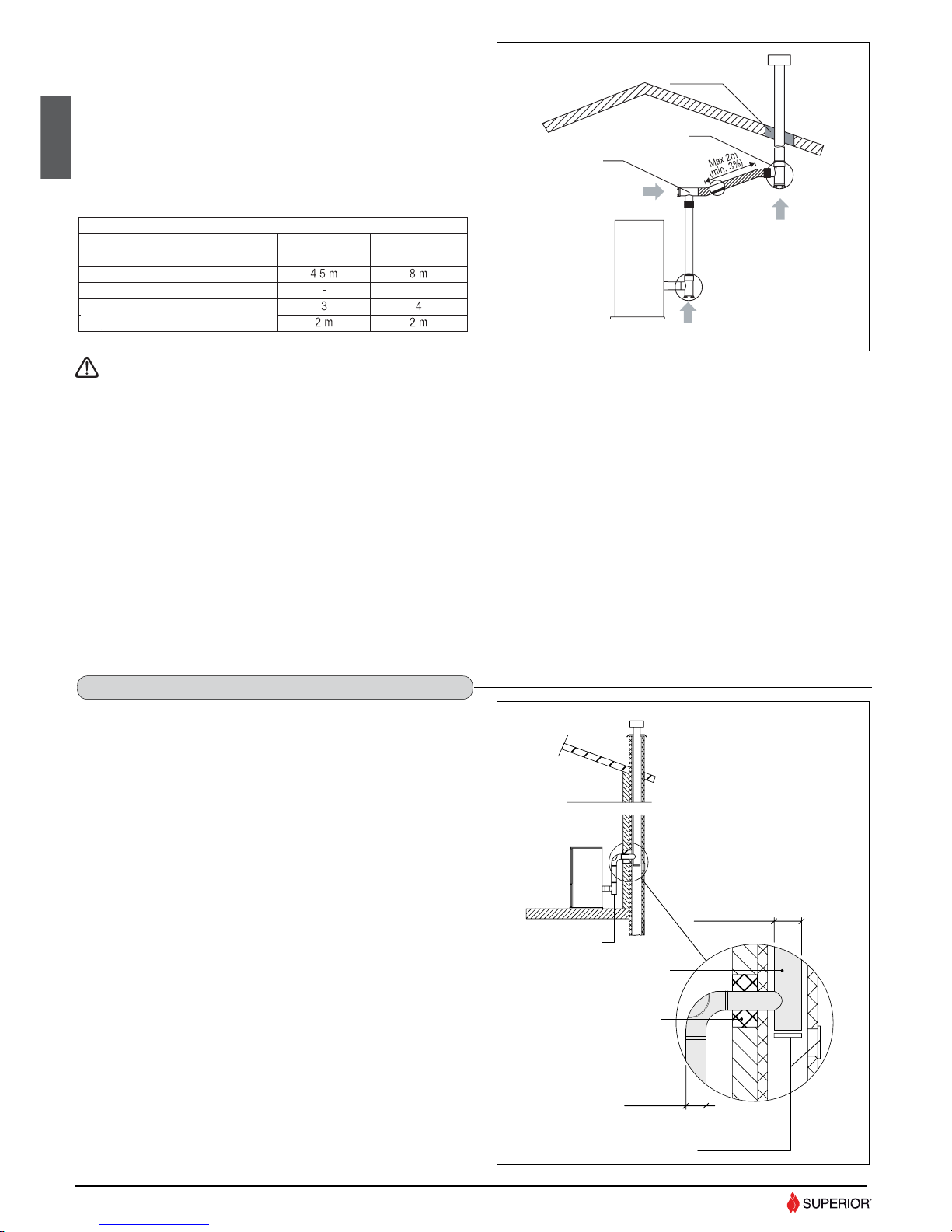
Every appliance must have a vertical fl ue pipe operating by natural draught to
discharge the combustion gases outdoors.
The fl ue must:
- comply with regulations in force in the place of installation of the appliance;
- be tight to the products of combustion, waterproof, suitably insulated, made
with materials resistant to corrosion by the gases and to stress;
- be connected to just one stove, fi replace or extraction hood (Fig. 2);
- be properly sized, with constant free internal section, equal to or greater than
the diameter of the fl ue pipe of the stove and at least 3.5 m in length (Fig. 2);
- be mainly in a vertical position with a defl ection from the axis of no more
than 45° (Fig. 2);
- be at a suitable distance from combustible or fl ammable materials, ensured
by an air gap or suitable insulating material;
- be of uniform internal section, preferably round. Square or rectangular
sections must have rounded corners with a radius of at least 20mm and a
maximum ratio between the sides of 1.5 (Fig. 3-4-5).
- The walls must be smooth if possible and without narrowing. Bends must
be regular and without discontinuity (Fig. 6).
It is forbidden to make fixed or mobile apertures on the flue pipe
to connect appliances other than the one to which it is already
connected.
It is forbidden to pass other air ducts or service pipes inside the
flue pipe, however large it is.
If the flue pipe is an incorrect size or installed other than in
compliance with the above instructions, the factory cannot be
held liable for malfunctioning of the product, damage to property
or injury to persons or animals.
We reccomend that the fl ue must have a chamber for collecting solid matter and any condensate located below the connection and which may be easily
inspected by means of an airtight door. (Fig. 1)
Fig. 2
Fig. 6Fig. 5
Fig. 4Fig. 3
1.1 SINGLE CHIMNEY OR FLUEWAY
DT2010024-02
1.2 SOOT INSPECTION
DT2010031-01
DT2030049-00
DT2030190-00
DT2030189-00
DT2030188-00DT2030050-00
5
English
3.5 m MINIMUM
Deposit of creosote
Deposit of creosote
Page 6
H07023380 / DT2000477-03
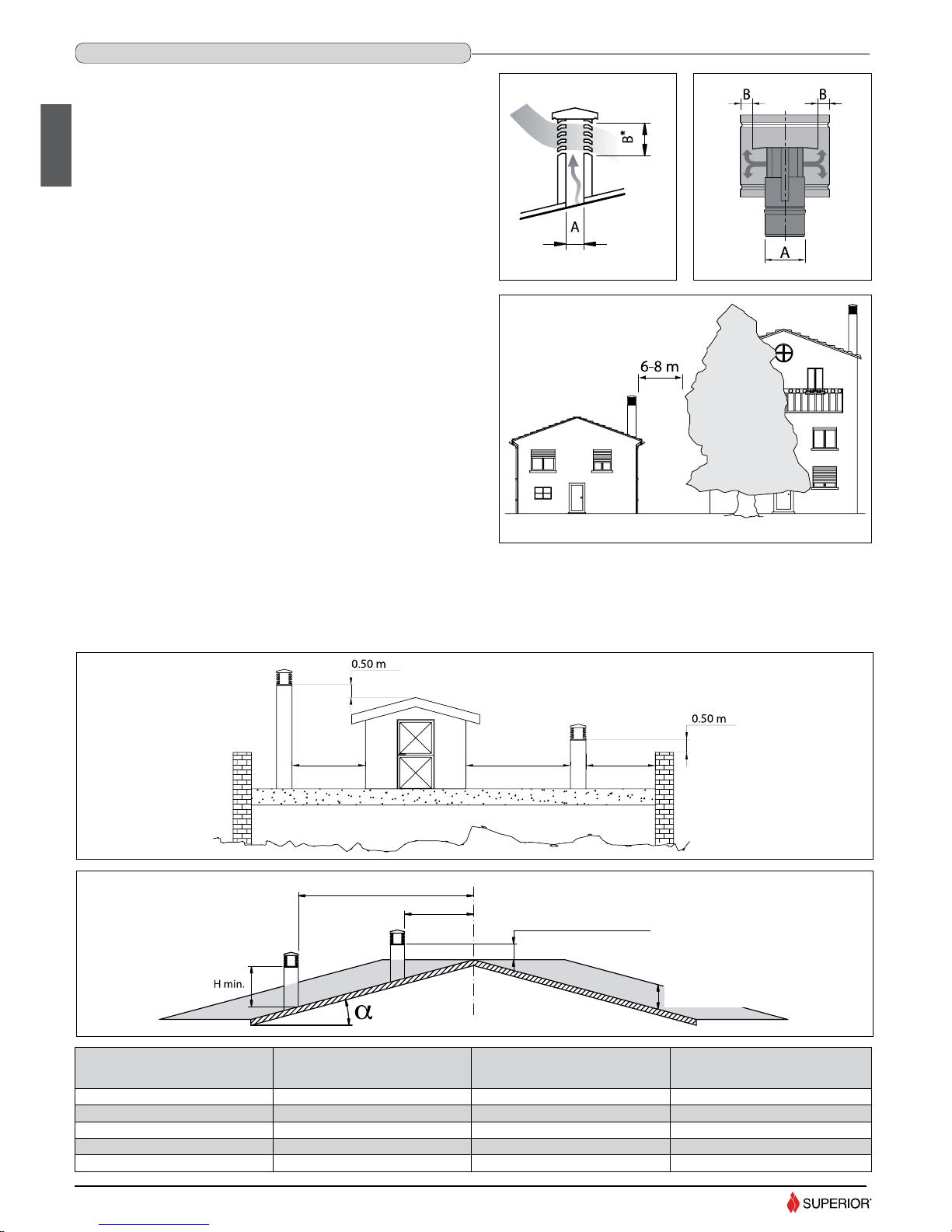
The chimney stack is a device fi tted on the top of the chimney that is designed
to aid dispersion of the products of combustion in the atmosphere.
The chimney stack must comply with the following requirements:
it must have an internal section and shape the same as the fl ue (A);
it must have a useful outlet section (B) of not less than twice that of the
fl ue (A);
the part of the chimney that emerges from the roof or remains in contact
with the outside (e.g. in the case of a fl at roof), must be covered with brick
or tile elements and in any case well insulated;
It must be built in such a way as to prevent the penetration of rain, snow
and foreign matter into the fl ue and to ensure that in the event of winds
from all directions and angle, discharge of the combustion products is
assured (chimney stack with down-draught cowl).
Recommended distances for correct chimney operation.
To ensure trouble-free operation of the chimney and allow correct dilution of
the products of combustion in the air, the chimney stack must be installed
at the distances given below:
6-8 metres from any buildings or other obstacles that are higher than the
chimney stack;
50 centimetres higher than any obstacles located at a distance less than
5 metres;
outside the refl ux area. The size and shape of this area differ according to
the angle of inclination of the roof and it is therefore necessary to adopt the
minimum heights shown below.
Fig. 9
Fig. 8
B equivale al
doppio di A
Fig. 7
α
A H minimum
H minimum
Z
15°
30°
45°
60°
1,85 m
1,50 m
1,30 m
1,20 m
1,00 m
1,30 m
2,00 m
2,60 m
0,50 m
0,80 m
1,50 m
2,10 m
1.3 CHIMNEY STACK
DT2010025-03
6
DT2030052-00
DT2030191-00DT2030051-00
English
Example: Check the slope of the roof (column α), and the anticipated
distance of the chimney stack from the axis of the ridge (column A); if the
distance is greater than “A” the height of the chimney stack may be read
in (column H); if the distance is less than “A” the chimney stack must rise
above the ridge by 0.5 metres.
* B it is twice
of to A
Fig. 10
Fig. 11
FLAT ROOF
over 5 m5 m or less 5 m or less
SLOPING ROOF
distance more than A
ridge axis
distance
min. than A
0.50 m above the ridge
height of refl ux
area z
DT2030053-00
DT2030192-00
Pitch of the floor
Horizontal width of reflux area
from ridge axis
Minimum height of
outlet from root
Height of reflux area
Page 7
H07023380 / DT2000477-03
Fig. 13
Fig. 14
Fig. 15
Fig. 12
1.4 FRESH AIR INTAKE
DT2010539-03
7
English
DT2030193-00
DT2030194-00
DT2030195-00
DT2030054-00
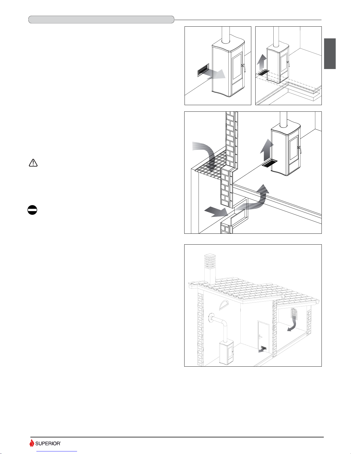
To ensure trouble-free operation the stove/fi replace must have the necessary
air available for combustion and this is provided through the fresh air intake.
The fresh air intake must:
- have a total free cross section at least equal to the size given in the
paragraph “TECHNICAL DATA”;
- be protected by a grille or suitable guard provided it does not reduce the
minimum recommended section;
- be in a position whereby it cannot be obstructed.
The airfl ow necessary for the fi re may be obtained in different ways:
- through a fresh air intake direct into the room of installation; (Fig. 12)
- with ducting through pipes direct to the room of installation, increasing the
recommended minimum free cross section by at least 15%; (Fig. 13)
- from an adjacent room to the place of installation provided this air flows
freely through permanent apertures communicating with the outside.
(Fig. 14-15)
The adjacent room from which air is taken must not have a low
pressure compared to the exterior due to a counter draught
caused by the presence in that room of another appliance in use
or of a suction device.
The permanent apertures in the adjacent room must comply with
the requirements given above.
Combustion air must not be taken from adjacent rooms used as
a garage or a combustible materials store or for activities posing
a fi re hazard.
Page 8
H07023380 / DT2000477-03
1.5 INSTALLATION ENVIROMENT
DT2010033-01
Check the load-bearing capacity of the fl oor referring to the weight of the product given in the paragraph “TECHNICAL DATA”.
If the fl oor has an unsuitable load-bearing capacity, take adequate countermeasures.
Check the heating capacity of the appliance by comparing the rated power given in the paragraph “TECHNICAL DATA” with the power required by the
environment to be heated.
The energy requirement may be calculated approximately by multiplying the square metres of area by the height of the ceiling; the result is then multiplied
by a coeffi cient, which depends on the degree of insulation of the building, that is, on internal and external factors of the dwelling:
a) Internal factors: type of window and door frames, thickness of the insulation and walls, type of building materials, presence of stairwells, walls with
extensive glazing, high ceilings, position of the rooms to be heated in relation to other adjacent heated or unheated rooms, …
b) External factors: geographical position, average outdoor temperature, exposure, wind speed, latitude, altitude, …
Example of approximate calculation of the energy requirement to heat a fi xed volume to 18/20° C:
The coeffi cient that is normally used is determined according to the real conditions as they occur case by case.
From 0.04 to 0.05 kW per cubic metre in a well insulated environment
From 0.05 to 0.06 kW per cubic metre in a poorly insulated environment
3 rooms measuring 20m2 X (H ceiling) 2.7m = 162 m
3
(volume)
In an environment with a good degree of insulation, an average value (coeffi cient) of 0.045 kW may be taken
162 (volume) X 0.045 (kW) = 7.3 kW necessary (6300 kcal/h)
Conversion 1kW = 860 kcal/h
Consult a heating technician or engineer for a correct check and calculation of the requirement of the environments to be heated
(see “REFERENCE STANDARDS”).
1.6 LOAD-BEARING CAPACITY OF THE FLOOR
DT2010032-00
1.7 HEATING CAPACITY
DT2010130-01
8
English
The appliance should be installed in a location which allows safe and convenient use as well as easy maintenance. If the product being installed requires
an electrical socket, the room must also be provided with an earthed power supply in accordance with current regulations. The room where the appliance
is to be installed must comply with the following requirements.
It can not be used as a garage, store for combustible material or for activities with a risk of fi re.
It can not be in a vacuum in relation to the outside environment due to the effect of contrary draught caused by the presence in the room
where the fi replace is installed of another appliance or an extractor device.
Do not use two stoves, a fi replace and a stove, a fi replace and a wood-fi red cooking range, etc. in the same environment, since the draught
of one could affect the draught of the other.
- Devices suitable for cooking food with relative hoods without an extractor fan may only be used in kitchens.
- Gas appliances of type C are allowed (refer to current legislation and regulations in the place of installation)
Gas appliances of type B are not allowed (refer to current legislation and regulations in the place of installation).
The fi replace must not be used simultaneously with collective type ventilation ducts with or without extractor fan, other devices or other
appliances such as: forced ventilation systems or other heating systems using ventilation to change the air. Such systems could cause a
vacuum in the environment of installation even if installed in adjoining or communicating rooms.
The fi replace must not be used: in stairwells except in buildings with no more than two apartments; in corridors for common use; in
bedrooms; in bathrooms or shower-rooms.
Page 9
H07023380 / DT2000477-03
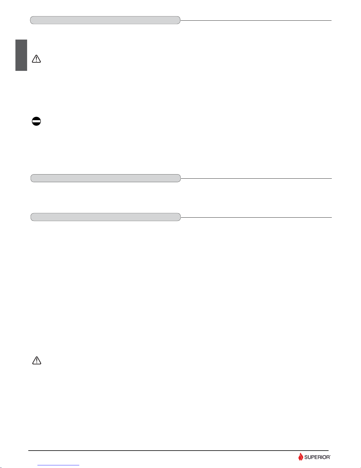
1.8 MINIMUM SAFETY DISTANCES
DT2011553-02
9
English
- The fl ueway must be made by specialised personnel or fi rms, as outlined below.
- The fl ue must be installed in such a way as to guarantee that periodic
cleaning can be carried out without dismantling any parts whatsoever.
- Pipes should always be sealed with silicone (not cement-based sealants) or
specially adapted gaskets/seals, which retain their strength and elasticity at
high temperatures (250°C), and should be fi xed with 3.9 mm ø self-tapping
screws.
1.9 CONNECTION TO THE FLUE
DT2010229-04
The pellet stove is not the same as other stoves. It has a forced
draught of fl ue gas by a fan, which keeps the fi rebox in a vacuum
and the entire fl ueway slightly pressurised. For this reason the
fl ue must be completely airtight and correctly installed to ensure
both trouble-free operation and user safety.
Do not install dampers or valves that could block the passage of
fl ue gas.
Do not connect to a fl ueway into which other appliances (boilers,
extractor hoods, etc.) discharge fumes or vapours.
Using the relative pipe clips, fi x the fl ue to the wall so that it does not
weigh on the smoke fan.
Fig. 19
DT2030337-00
Keep any combustible product such as wooden furniture,
curtains, carpets, combustible liquids, etc. well away from the
stove when it is lit (minimum distance 80 cm).
It is recommended that greater distances than those indicated
above be left all round the stove to make any necessary work
on the appliance easier.
Parete posteriore
Parete laterale
Parete laterale
B
B
A
D
STUFA
E E
F*
F*
SCARICO POSTERIORE
SCARICO
LATERALE
del focolare
Zona radiante dell'apertura
C
Protezione pavimento
DT2032441-0
Install the product in compliance with the recommended safety distances
from heat sensitive or inflammable materials and not inflammable, from
load bearing and other walls and also from wooden elements, furniture, etc.
In the case of flooring that is heat sensitive or inflammable the floor must
be protected with non-combustible insulating material, e.g. sheets of steel
plate, marble, tiles, etc.
The minimum distances are:
Connection to the flue must respect minimum safety distances from heatsensitive structural components or inflammable materials (wood panelling,
beams or ceilings, etc) shown in the figures.
* = Values referred to the use of original Superior flue pipes; if other pipes
are used, the safety fire regulations or fire codes of reference are applicable.
A 10 cm from the wall behind the stove
B 20 cm from the side wall
C 80 cm in the heat radiation area and from the hot air fan outlet
D 50 cm fl oor protection
E 30 cm (measured from the inner edge of the door)
F 5 cm from the fl ue gas outlet on the rear wall
DT2030335-00
Fig. 16
Fig. 17
Fig. 18
DT2032226-00
STOVE
Rear wall
Side wall
Side wall
Radiating Zone
Floor protection
Rear fl ue gas outlet
Side fl ue gas
outlet
Tee with sealing plug
Straight reducer
Ø 80/100 mm
Ø 100 mm
Ø 80 mm
Page 10
H07023380 / DT2000477-03
Pipes and maximum usable lengths
Pipes of painted aluminium-clad steel (minimum thickness 1.5mm), stainless
steel (AISI 316) or enamelled steel (minimum thickness 0.5mm) with a
nominal diameter of 80 or 100 mm (for pipes which run inside the fl ue
maximum diameter 150 mm) can be used.
The male-female connectors must have a minimum length of 50 mm.
The diameter of the pipes depends on the type of installation. The stove was
designed to take 80 mm diameter pipes but, as shown in Table 1, in some
cases the use of double-lined 100 mm diameter pipes is recommended.
Fig. 20
10
English
DT2030338-00
If you wish to use an existing chimney it is strongly recommended that
you have it checked by a professional chimneysweep to ensure that it is
completely airtight. The reason for this is that the smoke, because it is
slightly pressurised, can infi ltrate any cracks in the fl ue and escape into
living spaces. If upon inspection you fi nd that the chimney is not completely
sound, it is recommended that you insert piping made of new material. If the
existing chimney is wide enough we recommend a pipe with a maximum
diameter of 150mm. It is also recommended that you insulate the chimney
fl ue (Fig. 21 - 22).
Pipes and bends made by the factory are recommended for connection to the
fl ueway, since they are sized to fi t the fl ue outlet of the appliance.
Other pipes may be applied after adaptation and checking of the compatibility
of the coupling, taking into account that the pipes and bends must be made
in compliance with current regulations. In this case, however, the factory only
guarantees trouble-free operation for parts that it manufactures and that are
used according to specifi cations.
1.10 CONNECTING TO A CONVENTIONAL CHIMNEY
DT2010230-02
Losses in pressure associated with a 90° bend can be compared to those incurred by one metre of pipe. An inspectable union-tee can be
considered equivalent to a 90° bend.
EXAMPLE: if installing a section greater than 4.5m in length with 80mm diameter pipe, calculate the maximum usable length in the following ways:
- If a maximum of three 90° bends are used, the maximum length of the section will be 4.5m.
- If a maximum of two 90° bends are used and bearing in mind that a 90° bend can be replaced by one metre of pipe, the maximum length of the section
will be 4.5m+1m=5.5m.
- If a maximum of one 90° bend is used and bearing in mind that a 90° bend can be replaced by one metre of pipe, the maximum length of the section
will be 4.5m+1m+1m=6.5m.
Where 100mm diameter pipe must be used, connect it to the stove fl ue outlet with a 80mm union-tee then use a 80mm 100mm adaptor (not supplied by
Superior) (Fig. 19).
Union-tee
The use of this type of fi tting must allow for the collection of condensate mixed with soot, which builds up inside the pipe. It must also permit periodic
cleaning of the fl ue without the need to disassemble the pipes. This type of fi tting can be bought at Superior retail outlets together with the pipes. An example
is given below of a fl ueway connection, which allows complete cleaning without having to disassemble the pipes (Fig 20).
COMIGNOLO
RACCORDO A T
Ø 80 mm
ISOLANTE
Ø 150 mm MAX
INSERIMENTO DI UN TUBO
SPORTELLI PER
ISPEZIONE
CON CANNA FUMARIA
NON INTEGRA
Fig. 21
DT2030339-01
INSULATING
MATERIAL
DIRECTION OF
CLEANING
DIRECTION OF CLEANING
TEE
TEE
DIRECTION OF
CLEANING
TABLE 1 – LENGHT PIPES
TYPE OF INSTALLATION
WITH 80mm
DIAMETER PIPE
WITH DOUBLE-WALLED
100mm DIAM. PIPE
required
Maximum length (with three 90° bends)
For installations more than 1200m above sea level
Maximum number of bends
Length of horizontal sect. w/ minimum 3% gradient
CHIMNEY STACK
WITH DAMAGED FLUE
TEE
PIPE INSERTION
INSULATING MATERIAL
INSPECTION
WINDOWS
Page 11
H07023380 / DT2000477-03
The product must be installed and used in compliance with the manufacturer’s instructions and European and national standards as well as local
regulations.
When a fl ue pipe passes through a wall or a ceiling, special installation methods must be applied (protection, thermal insulation, distances
from heat-sensitive materials, etc.). See the paragraph “CONNECTION TO THE FLUEWAY”.
- It is also recommended that all elements made of combustible or infl ammable material, such as beams, wooden furniture, curtaining, fl ammable liquids, etc.
be kept outside the heat radiation range of the
fi replace
and at a distance of at least 80 cm from the heating block.
- For other information, see the paragraph “MINIMUM SAFETY DISTANCES” and “CONNECTION TO THE FLUEWAY”.
- The fl ue pipe, chimney stack, chimney and fresh air intake must always be free of obstructions, clean and checked periodically, that is, at least twice during the
seasonal period from the lighting of the
fi replace
and during its use. When the
fi replace
has not been used for some time it is advisable to carry out the checks
mentioned above. For further information, consult a chimneysweep.
- Only use recommended fuels (See section “FUEL”).
1.12 PREVENTION OF DOMESTIC FIRES
DT2010027-02
11
English
- If the connector has to pass through partitions or walls of infl ammable or
heat-sensitive materials, or through load-bearing walls, create:
an insulating barrier equal to or greater than 10cm around the connector
using mineral-based insulating material (rock wool, ceramic fi bre) with a
nominal density greater than 80kg/m3.
- If the connector has to pass through non-fl ammable partitions or walls,
create: an insulating barrier equal to or greater than 5cm around the
connector using mineral-based insulating material (rock wool, ceramic fi bre)
with a nominal density greater than 80kg/m
3
.
- Check that the connection to the fl ueway is gas/smoke-tight, since the
appliance operates in a vacuum.
- Check that the pipe does not penetrate too far into the fl ueway, thereby
choking the pipe for the passage of smoke and combustion gases.
Fig. 22
DT2030340-00
Ensure that all installation work is carried out to professional
standards.
An external fl ue can be used provided it complies with the following
requirements:
- Use only insulated stainless steel pipes (double-lined) fi xed to the outside
wall of the building (Fig. 23).
- There must be an inspection opening at the base of the fl ue to permit
periodic checks and maintenance.
- The fl ue must be fi tted at the top with a chimney stack with down-draught
cowl, also ensuring compliance with the safety distance from the roof ridge
as outlined in the section entitled “GENERAL RULES”, under “CHIMNEY
STACK”.
Fig. 23
DT2030341-00
Ensure that all installation work is carried out to professional
standards.
1.11 USING AN EXTERNAL FLUE
DT2010232-02
CLOSING FLANGE
SEALING FLANGE IN STAINLESS
STEEL OR ALUMINIUM
FRESH AIR INTAKE WITH
NON-CLOSABLE GRILLE
FRESH AIR INTAKE WITH
NON-CLOSABLE GRILLE
Page 12
H07023380 / DT2000477-03
2.0 FEATURES AND TECHNICAL DATA
Data obtained under laboratory conditions with pellet calorifi c value of 5 kWh/kg.
N.B. The above data may vary according to the characteristics of the pellets being used. (See section “FUEL”)
U.M.
MONIA
at rated power at minimum power
Rated / minimum thermal power kW 8.5 / 2.6
Smoke fl ow rate g/s 5.5 4.3
Average temp. of smoke at exhaust outlet °C 189.1 107.4
Minimum draught Pa 12
2.3 TECHNICAL DATA
DT2011602-01
Rated / minimum thermal power kW 8.5 / 2.6
Effi ciency % 89.1 86.8
CO content (with 13% O2) % 0.020 0.026
Maximum power rating W 370
Power rating at work W 90
Electrical power supply V 230
Frequency Hz 50
Frequency only for Japan Hz 60
Fuel tank capacity kg / (l) 16 / (25)
Exhaust outlet diameter cm ø 8
Fresh air intake with minimum useful section cm2 100
Hourly fuel consumption kg/h 1.8 0.6
U.M.
MONIA
at rated power at minimum power
Weight with cladding kg 98
English
2.1 FEATURES
DT2011592-00
Cladding: enamelled steel with majolica insert
Interior: steel
Baffle plate and hearth: cast iron
Grate: cast iron
Door: cast iron with ceramic glass heat resistant up to 750°C
Handle: enamelled steel
Control panel: display with digital controls and remote control (optional)
Timer thermostat: standard with daily, weekly and weekend programming modes divided into two time bands
Power setting: from 1 to 4
Ash drawer: removable
Fuel: natural pure wood pellets (see “FUEL” section)
Heating: forced ventilation
Technical data for fl ue calculations
2.2 ACCESSORIES AND EQUIPMENT
DT2011648-00
Room sensor NTC 10K
Cable L=200 Schuko IEC
Pellet stove door handle tool
Grate baffl e plate
provided
provided
provided
provided
Grey silicone paint spray can
optional
Humidifi er
optional
MONIA
Description
Side fl ue gas outlet kit optional
Remote control kit optional
Pipes and elbows for connection to the fl ueway optional
Floor protection optional
Packing sizes (DxWxH) cm 55x60x116
GPRS module for remote stove control
optional
12
DT2011591-00
Page 13
H07023380 / DT2000477-03
54
6
18
! 8scarico
18
Dimensioni in cm
48
99
33 *
8,3
27
* Quota minima da rispettare per scarico laterale (optional)
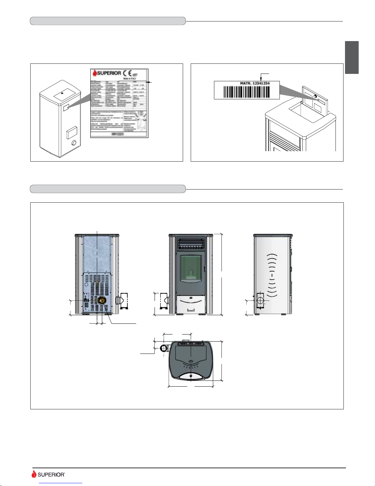
Every product is identifi ed by a rating plate showing the model and the performance of the appliance as well as a plate giving the serial number.
The rating plate is located on the rear panel of the stove, while the plate with the serial number is located on the underside of the hopper lid.
A label bearing the serial number is also applied on the cover last page of the “Installation, operation and maintenance” booklet.
Always give the information shown on these plates to the dealer or the Service Centre when requesting service or spare parts.
DT2032205-0
NOME
PRODOTTO
DT2032204-0
NUMERO MATRICOLA
English
2.4 PRODUCT IDENTIFICATION DATA
DT2011541-00
2.5 DIMENSIONS
DT2032294-00
Fig. 24
Fig. 25
PRODUCT
NAME
SERIAL NUMBER
Measurements in cm.
* Minimum measurement for the side flue gas outlet (optional).
13
Page 14
H07023380 / DT2000477-03
F
N
FUMI
SCAM
COC
ACC
AL1
DISPLAY
SERIALE
AMB
EXT
BL-
RO+
ENC
+5V
GND
BLU
A
C
D
E
F
G
H
L
M
N
O
P
Q
R
S
V
1 1
2
2
2
2
5
3
3
3
4
5
4
5
5
6
6
6
7
5
3
J
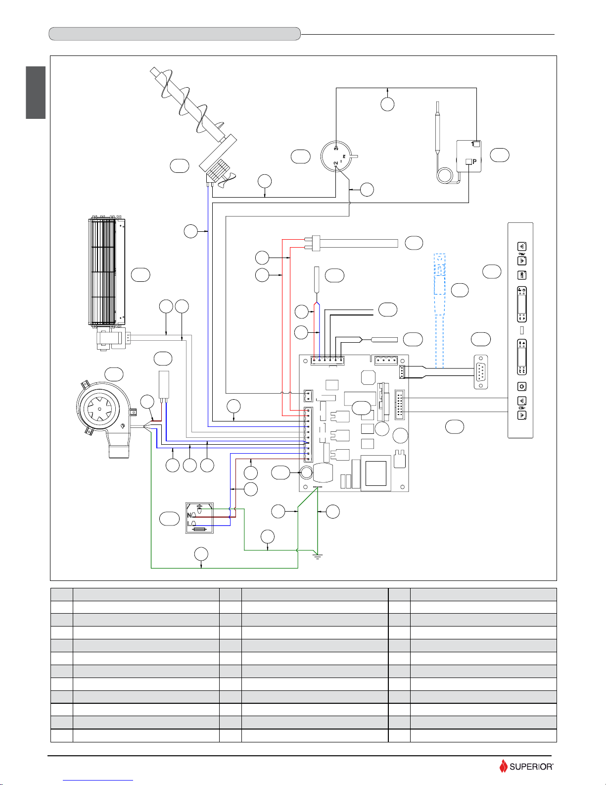
2.6 WIRING DIAGRAM
DT2032293-02
POS. KEY TO PARTS
A Control display
B C Room fan
D Pellet-loading auger
E Flue gas fan
F Capacitor
G N.O. Pressure switch (normally open)
H N.C. 80° thermostat (normally closed)
I J Remote control receiver (optional)
POS. KEY TO PARTS
M
Power supply with fuse (5X20 4AH250V)
N Smoke sensor
O Room sensor
P External thermostat
Q Serial port DB9
R Motherboard
S Fuse 5X20 4AL250V
T U V Flat cable
NO. KEY TO COLOURS
1 White
2 Yellow-green
3 Black
4 Brown
5 Blue
6 Red
7 Grey
L Igniter plug Z -
English
14
Page 15

H07023380 / DT2000477-03
English
4.0 INSTALLATION
Pursuant to current regulations on the safety of electrical equipment, you
must contact a Superior After-Sales Service Centre or a qualifi ed electrician
for all and any work connected with installation, maintenance or servicing
that involves access to electrical parts.
Cladding
Having completed assembly of the stove and installed any external room
thermostat, check that the humidifi er (optional) is properly inserted into its
seat (see the paragraph “HUMIDIFIER”) and fi nally fi t the ceramic panel into
the top. (Fig. 27)
Power cable (7).
• The stove/fi replace comes with a power cable which must be connected
to a 230V/50Hz mains socket. Connection to the rear of the stove/fi replace
is shown in fi g. 28.
• The power rating is indicated in the paragraph “TECHNICAL DATA”.
Connection to the DB9 serial socket (7)
• The appliance has a DB9 serial socket, which is used to check appliance
operation. Controls should be carried out by authorised personnel at the
time of installation or during maintenance.
• The optional GPRS kit, if ordered, may be connected to the DB9 serial
socket.
The appliance must be connected to an efficient earthing/
grounding system.
Ensure that in its normal position the power cable does not
come into contact with any heated parts.
Ensure that the electrical plug is accessible also after
installation of the stove.
Room sensor connection (5).
• When installing the stove/fi replace, it is necessary to connect the room
sensor (provided) to the correct jack (fi g. 28). The sensor can be positioned
as shown in fi g. 29, otherwise remove the band, uncoil the lead and then
place the sensor in a spot where a more accurate room temperature reading
can be obtained.
Pipe tap (3).
• The appliance has an external socket for measuring the pressure (vacuum)
of the fl ue gas outlet pipe. This control and verifi cation should be carried out
by authorised personnel at the time of installation or during maintenance.
1
2
3
7
4
1 External socket for connection of room
sensor.
2 Socket for power lead.
3 External pressure pipe tap.
4 Knockout for inserting cable gland PG7
for connection of external thermostat.
5 Room sensor connection.
6 Power cable connection.
7 DB9 serial socket
DT2032282-0
5
6
Fig. 29
4.1 ELECTRICAL CONNECTION AND CONTROLS
DT2011601-01
DT2032296-00
Fig. 28
3.0 PREPARING FOR INSTALLATION
To prevent accidents or damage to the product we recommend the following:
- unpacking and installation must be carried out by at least two people;
the product must always be moved and handled with suitable equipment in
- full compliance with current safety regulations;
- the packaged product must be kept in the position according to the
directions shown by the diagrams and notices on the pack;
- if ropes, straps or chains are used, ensure that they are able to take the
weight of the pack and that they are in good condition;
- use slow continuous movements when moving the pack to avoid jerking
the ropes, chains, etc.;
- do not tilt the package excessively to avoid toppling;
- never stand in the vicinity of loading/unloading equipment (forklift trucks,
cranes, etc.). Before proceeding with installation, remove the securing
brackets (A) having removed the relative fastening screws. (Fig. 26)
Unpack the product being careful not to damage or scratch it, take
the accessories kit and any pieces of polystyrene or cardboard
used to wedge moveable parts etc. out of the stove.
Keep packaging (plastic bags, polystyrene, etc.) out of reach
of children, since it could be a potential source of danger, and
dispose of according to local regulations.
To make moving and handling of the stove easier for installation
purposes, it is advisable to remove the cladding in accordance
with the procedure described in the paragraph “REMOVING THE
CLADDING” and then refi t it upon completion of installation.
If you decide to install the stove without removing the cladding, take
great care not to buckle, scratch or in any way damage the bottom
of the side panels and the lower front panel.
DT2011688-00
Fig. 27
DT2032281-00 DT2032282-00
A
A
Fig. 26
DT2032443-00
15
DT2011597-00
DT2011593-01
Page 16

H07023380 / DT2000477-03
The appliance is designed for connection to an external room thermostat.
To connect the external thermostat use cable type 2x0.5mm2 clamped with
a PG7 cable gland to be inserted in the appropriate hole in the rear panel
(Fig. 32).
This operation must be carried out by authorised personnel.
Fig. 30
To install, proceed as follows:
- Cut off the electricity to the appliance;
- Remove the right side panel (see the paragraph REMOVING THE
CLADDING);
- Remove the knockout to be found in the rear panel (position 4 – Fig. 28);
- Clamp the thermostat cable with the PG7 cable gland and insert the gland
into the hole in the rear panel (Fig. 32);
- Connect the thermostat terminal to the two-pin terminal of the electronic
board (Fig. 31);
- Refi t the panel, proceeding in the reverse order to removal.
1 Thermostat.
2 Electronic board 2-pin terminal.
3 Cable gland
.
4 Thermostat cable terminal.
4.2 INSTALLING THE EXTERNAL THERMOSTAT
DT2011598-00
English
Installation can be carried out with any type of room thermostat
but requires a PG7 cable gland similar to the one shown in fi g
30. To connect the thermostat to the electronic board, see the
wiring diagram.
DT2032283-0
Fig. 31
DT2032284-0
Fig. 32
4.3 REMOVING THE CLADDING
DT2011600-00
DT2032298-0
A
B
Fig. 33
If work has to be carried out inside the cladding, the side panels must be
removed as follows:
- remove the upper grille [A] after unscrewing the 4 fastening screws [B].
(Fig. 33)
- Remove the 2 screws [C] that secure the lower front panel [D], lift it
slightly and then pull it outwards to remove. (Fig. 34)
DT2032299-0
D
C
Fig. 34
16
DT2030076-00
Page 17

H07023380 / DT2000477-03
English
The product is supplied with the fl ue gas outlet at the rear.
By purchasing the relative kit it is, however, possible to have an outlet on the
left side of the stove. Proceed as follows to install the kit:
- remove the left side panel (see the paragraph REMOVING THE CLADDING).
- Remove the rear stove panel [A]. (Fig. 37)
- Remove the smoke sensor after having removed the relative fastening
screw [B].
- Remove the screw securing the fl ue outlet pipe [C], to be found in the lower
part of the actual pipe.
- Draw the rear fl ue gas outlet pipe [D] out of the stove (once removed the
pipe may be disposed of). (Fig. 38)
4.4 SIDE FLUE GAS OUTLET (OPTIONAL)
DT2011599-00
DT2032323-0
A
Fig. 37
DT2032323-00
DT2032324-0
D
B
C
Fig. 38
- Remove the side panel after unscrewing the 2 front screws [E] (Fig. 35) and
loosen the rear screws [F] that secure it. (Fig. 36)
- Follow the same procedure for the other side.
- Refi t the cladding by repeating the above steps in the reverse order.
DT2032309-0
E
Fig. 35
DT2032310-0
F
Fig. 36
17
Page 18

H07023380 / DT2000477-03
English
G
F
Fig. 41
DT2032329-00
- Replace the removed pipe [D] with the side fl ue gas outlet connection [E] to
be found in the kit, inserting it fully into its seat and taking care to seal it with
a gasket and a silicone-based (not cement-based) sealant. (Fig. 39)
- Secure the fl ue gas outlet connection [E] with the previously removed screw [C].
- Refi t the smoke sensor, ensuring that it is fully inserted and securing it with the
screw [B], which must not be overtightened. (Fig. 40)
- Refi t the rear panel [A].
- Take the previously removed left side panel and use a screwdriver to remove
the knockout [F] to be found in the lower part, taking care not to scratch or
buckle the panel.
Apply the edge gasket [G] provided in the kit around the edge of the hole
made in the panel. Cut off any excess gasket. (Fig. 41)
- Refi t the left side panel, proceeding with the steps described for removal in
the reverse order.
- Connect to the fl ueway in accordance with the instructions given in the
section “GENERAL RULES”.
- Finish installing the cladding.
DT2032326-0
E
Fig. 39
DT2032327-0
E
B
C
Fig. 40
DT2032440-0
H
Fig. 42
It is advisable to secure the gasket with a few drops of high heatresistant silicone.
When installing with side fl ue gas outlet, the MINIMUM distance
of the fl ue gas outlet pipe from the stove is given in the paragraph
“DIMENSIONS”.
This measurement is obtained by inserting a pipe with diameter
80 mm and length 158 mm (measurement H - Fig. 42) between
the side fl ue gas outlet connection and the union tee.
18
Page 19

H07023380 / DT2000477-03
English
4.5 REMOTE CONTROL KIT (OPTIONAL)
DT2011677-01
DT2032445-0
B
A
Fig. 43
- Referring to the paragraph “REMOVING THE CLADDING”, remove the lower
front panel and the right side panel.
- Remove the connector of the DB9 port from the connexion [A] on the
electronic board. (Fig. 43)
- Connect the cable with receiver to the electronic board and the DB9 port, as
shown in the wiring diagram. (Fig. 44)
- Place the receiver that has just been installed in the front of the stove,
ensuring that the cable runs inside the stove and securing it with the clamps
[B] to be found in the base and which already hold the smoke extractor fan
cable. (Fig. 43)
- Fit the remote control receiver [C], in the direction as shown in the fi gure to
the side, onto the inner face of the removed front panel and fasten it to the
threaded bush using the screw provided in the kit. (Fig. 45)
- When installing align the spherical rounded part of the receiver [C] with the
central slot in the lower front panel [E].
- Check that the remote control receiver cable cannot come into contact with
parts of the stove that may become hot when the stove is in use.
- Refi t the previously removed cladding.
- Use the remote control functions as described in the section “USE”
DT2032447-0
A
C
Fig. 44
DT2032448-0
C
D
C
E
Fig. 45
Incorrect alignment can impair remote control reception.
If the remote control kit is installed, it’s not possible to install at
the same time the GPRS module and vice versa.
19
Page 20

H07023380 / DT2000477-03
English
The wood pellet is obtained by pressing wood sawdust left over from the
working of natural dried wood. The typical small, cylindrical form is obtained
by passing the material through a die. Thanks to lignin, a natural element
which is released during the pressing of the raw material, the pellets acquire
a good consistency and compactness without requiring treatment with
additives or caking agents.
There are various types of pellet on the market with qualities and
characteristics that vary depending on the processes they have undergone
and the type of wood used in their production.
Since the characteristics and quality of the pellet considerably affect
stove performance, efficiency and proper operation, we recommend
that you use high-quality pellets.
The factory has tested and programmed its stoves and can ensure
best performance and trouble-free operation using pellets with the
following specific characteristics:
This “customisation” of stove settings must be carried out at
a Superior Service Centre or by specially qualified personnel
authorised by the factory.
Using pellets that are out of date or not in conformity with the
manufacturer’s recommendations not only damages the stove
and jeopardises its performance, but can render the guarantee
null and void and relieves the manufacturer of all liability.
Diameter, approx.
Net heat value, approx.
Components
Length, approx.
Apparent density, approx.
Specifi c weight, approx.
Moisture content, approx.
Residual ash, approx.
N.B. the above data refer to beech/fi r wood pellets
Pellet characteristics
6 - 6,5 mm
5 kWh/kg
Natural pure wood pellet
10 - 30 mm
650 kg/m
3
> 1,0 kg/dm
3
< 8 %
< 0,5 %
5.0 FUEL
DT2010233-04
To ensure trouble-free operation:
DO NOT use pellets with dimensions other than those recommended by the
manufacturer
DO NOT use poor quality pellets containing sawdust, bark, maize, resins or
chemical substances, additives or adhesives.
DO NOT use damp pellets.
Choosing other and unsuitable pellets:
- obstructs the grate and flue gas pipes;
- increases fuel consumption;
- reduces efficiency;
- means that proper stove operation cannot be guaranteed;
- causes dirt to build up on the glass;
- leaves particles which have failed to burn and heavy cinders.
The presence of moisture in the pellets increases their volume and causes
them to split which in turn causes:
- malfunction of the fuel-loading system;
- inefficient combustion.
Pellets should be stored in a sheltered, dry place.
To use good quality pellets with dimensions and heat-producing properties
other than those recommended above, it will be necessary to change the
stove operating parameters.
To load the pellets into the hopper it is advisable to tear off the edge of the
sack and empty the sack directly into the hopper. This makes filling easier
and avoids pouring pellets on top of the stove.
Do not allow sawdust to accumulate on the bottom of the hopper.
Do leave leftover pellets on top of the stove – they could catch fire!
5.1 LOADING THE PELLETS
DT2010730-00
DT2030459-00 DT2030460-00
20
Page 21

H07023380 / DT2000477-03
English
6.0 USE
• Do not use the stove as a cooking appliance.
• Ensure that the room in which the stove is installed is suffi ciently well ventilated (fresh air intake).
• Ensure that all joints in the fl ue are hermetically sealed using a silicone- (not cement-) based sealant which is resistant to temperatures of up to 250ºC
and which shows no sign of deterioration.
• Check (or have checked) regularly that the fl ue is clean.
• Under no circumstances use fuels other than pellets.
• Remove any deposits of unused pellets left by failed ignition before restarting the stove.
During operation some parts of the stove (door, handle, controls, ceramic parts) can reach high temperatures. Take great care and all the
necessary precautions, especially in the presence of children, the elderly or disabled and pets.
Keep any infl ammable object well away from the stove while it is in use (MINIMUM 80 cm from the front panel).
While in use the door must remain closed and the glass must be present and intact. The removal of the protective grille inside the pellet
hopper is strictly prohibited. If replenishing with pellets while the stove is lit, ensure that the bag does not come into contact with any
hot surfaces
DT2011649-00
DT2010035-05
6.1 CONTROL PANEL
DT2011650-00
- The stove is fi tted with a digital control panel, which allows the user to control the various functions.
- When the stove is connected to the electrical system but is not in the operating mode, the actual time (e.g.: 12:30) appears in the left part of the display,
while the readout OFF appears in the right part.
DT2032436-00
The control panel keys and their various functions are listed below. These have been numbered in order to make identifi cation easier.
Key 4
(ON-OFF)
Key 5-6
(adjustment/ selection)
Key 1-2
(adjustment/ selection)
Used for:
- manual startup and shutdown.
- exit from programming mode.
When the stove is in operation, they can be used:
-to set the power between 1 and 4
In the stove programming stage, they are used:
- to access the programming menu (key 6)
- to scroll the menu programs and the timer-thermostat
- to scroll time meter storage menu (parameter submenu)
When the stove is in operation, they can be used:
- to set the room temperature between 7°C and 30°C
- to read the temperature and actual time (key 1)
In the stove programming stage, they are used:
- to select the language
- to select the day and time for clock settings
- to set the timer-thermostat parameters
- to enable the buzzer
- to set mode display
Key 3 (SET)
Used for:
- confi rmation of the selected menu
Timer functions
The LED lights up if the timer is activated.
Temperature
The LED lights up when the desired temperature is reached.
Remote control reception
The LED lights up if data are received from the remote control (optional)
Programming
The LED lights up when programming is in progress.
Fuel loading
The LED lights up when the fuel-loading auger is in use.
Pilot light
The LED lights up when the pilot light is on.
-
-
-
-
Control display
Displays:
- actual time/room temperature
- power setting
- set functions
21
Page 22

H07023380 / DT2000477-03
English
6.2 SETTING THE LANGUAGE
DT2011651-00
SEL LINGUA
SET OROLOGIO
SET CRONO
MENU PARAMETRI
ITA
DE
ENG
FRA
TARATURE FABBRICA
BANCA DATI
TARATURE CARICO
TARATURE ASP-FUMI
ANNULLA ORE PAR
ANNULLA ALLARMI
MEMORIE CONTAORE
PROGRAMMA GIORNO
PROGRAMMA SETT
PROGRAMMA FINE SETT
ABILITA CICALINO
ON
OFF
MODO DISPLAY
STATO STUFA
USCITA
ORE
TEMP
LU
MA
ME
GI
VE
SA
DO
Description of activity
Display
Press key 6 for a few seconds.
The scrolling readout “SELECT LANGUAGE” will appear on the right part of the display.
Confi rm by pressing the SET key.
This function allows one of the four languages available to be set on the display according to the country where the product is installed.
SELECT LANGUAGE
Using key 1 or 2, scroll the languages on the left display until the required language appears.
E.g.: ENG
Confi rm by pressing the SET key.
After confi rmation, the scrolling readout “FUNCTION ENABLED” appears on the right display,
after which the initial display returns.
FUNCTION ENABLED
6.3 PROGRAMMING
DT2011652-00
Press key 6 for at least 5 seconds to enter stove programming.
- Repeatedly press key 5 or 6 to scroll the main menu, which appears on
the right-hand display.
- Having selected the function to be programmed, confi rm using the SET
key. Now display the submenus by repeatedly pressing key 1 or 2 for the
left-hand display and 5 or 6 for the right-hand display.
- Confi rm selection using the SET key and proceed in the same way until
the readout “FUNCTION ENABLED” appears on the right display. The stove
now returns to the initial display.
Repeat the above steps for each menu to be programmed.
See the appropriate table to programme each function.
- Press key 4 once to return to the previous menu.
DT2032300-00
SELECT LANGUAGE
SET CLOC
SET CHRONO
MENU PARAMETERS
ENABLE BEEP
MODE DISPLAY
ESC
STATE STOVE
HOUR
TEMP
ON
OFF
MO
TU
UE
TH
FR
SA
SU
ITA
DE
ENG
FRA
PROGRAM DAY
PROGRAM SETT
PROGRAM SET EN
SETTINGS FACTORY
DATA BAN
SETTINGS LOAD
SETTINGS SMO
RESET PARTHOUR
RESET ALARM
MEMORY COUNTERS
22
Page 23

H07023380 / DT2000477-03
English
The timer allows the user to programme the stove to start up and shut down automatically without any manual intervention.
Daily, weekly and weekend programmes can be selected with a maximum of two operating cycles in two separate timetable bands.
For example: Cycle 1: from 6am until 9am
Cycle 2: from 8.30pm until 11pm
In the DAILY programme the two timetable bands once established can be activated or deactivated for all the days of the week.
For example: if you want the stove to operate from 6am to 9am every day.
In the WEEKLY programme the two timetable bands once established can be activated or deactivated for each day.
For example: if you want the stove to operate from 6am to 9am on Monday, Tuesday, but not on Wednesday, and so on.
In the WEEKEND programme the two timetable bands once established can be activated or deactivated for Friday, Saturday and Sunday.
For example: if you want the stove to operate from 6am to 9am on Friday, Saturday, but not on Sunday.
This kind of timer allows you to have three programmes (DAILY, WEEKLY and WEEKEND) stored permanently. The programmes can be activated or
deactivated using the SET CHRONO menu. It is advisable to have only one programme active at a time to avoid overlapping.
WHEN USING THE TIMER FOR THE FIRST TIME, SET THE CLOCK WITH THE CURRENT DAY, HOUR AND MINUTES, as with a new watch. To
set the actual time, see the table SETTING THE CLOCK. This setting will only be necessary the fi rst time of activating the clock.
If several programs are active with overlapping times, the stove will start up with the fi rst programmed start time and will always stop
at the fi rst set time irrespective of the daily, weekly or weekend program.
6.5 TIMER
DT2011653-00
6.4 PROGRAMMING THE CLOCK
DT2011643-00
Description of activity
Display
Press key 6 for a few seconds. Use key 5 or 6 to scroll the menu that appears on the right
display until the scrolling readout SET CLOC appears.
Confi rm by pressing the SET key.
Correct time setting is necessary to be able to use all the functions where time is involved.
Setting the clock entails programming the following values: day, hour and minutes.
These values are displayed in sequence upon pressing the SET key.
SET CLOC
Using key 1 or 2, scroll the hours of the day that appear on the left display until the required
hour appears.
Confi rm by pressing the SET key.
DAY (scrolling readout)
Using key 1 or 2, scroll the minutes of the day that appear on the left display until the
required minutes appear.
Confi rm by pressing the SET key.
Using key 1 or 2, scroll the days of the week that appear on the left display until the required
day appears.
Confi rm by pressing the SET key.
MINUTES (scrolling readout)
The display automatically returns to its initial status.
HOURS (scrolling readout)
23
Page 24

H07023380 / DT2000477-03
English
Description of activity
Display
Press key 6 for a few seconds. Use key 5 or 6 to scroll the menu that appears on the right
display until the scrolling readout SET CHRONO appears.
Confi rm by pressing the SET key.
SET CHRONO
The scrolling readout PROGRAM DAY appears on the right-hand display.
Confi rm by pressing the SET key.
PROGRAM DAY
Use key 1 or 2 to scroll the options ON, to enable the daily program, OFF, to disable.
Confi rm by pressing the SET key.
If you have disabled the program by selecting OFF and do not want to proceed with
programming, press key 4 to exit. Press key 4 once to return to the SET CHRONO menu;
press twice to return to the initial display.
DAILY PROGRAM
ENABLE DAY (scrolling readout)
Use key 1 or 2 to set the start time of the fi rst operating cycle. Each time the key is pressed
the time advances by 10 minutes.
For automatic fast advance, hold the key pressed down for a few seconds.
Confi rm the set time by pressing the SET key.
START D PROGRAM 1 (scrolling readout)
Use key 1 or 2 to set the stop time of the fi rst operating cycle. Each time the key is pressed
the time advances by 10 minutes.
For automatic fast advance, hold the key pressed down for a few seconds.
Confi rm the set time by pressing the SET key.
STOP D PROGRAM 1 (scrolling readout)
It is possible not to set the stop time by setting the readout to OFF. Use key 1 or 2 to scroll the
timetable band to fi nd OFF, which appears at the end of the 24-hour cycle.
Confi rm by pressing the SET key.
STOP D PROGRAM 1 (scrolling readout)
Press key 1 or 2 to set the required power level during the fi rst operating cycle.
Confi rm by pressing the SET key.
SET D PO 1 (scrolling readout)
Press key 1 or 2 to set the required room temperature during the fi rst operating cycle.
Confi rm by pressing the SET key.
SET TEMP ROOM 1 (scrolling readout)
Programming automatically passes to the second operating cycle. To continue programming
for the second cycle, proceed in sequence with the steps given for the fi rst cycle. The number
2 appears on the display, indicating the second operating cycle. If you do not want to program
a second cycle, set START and STOP of the second programming cycle to OFF.
START D PROGRAM 2 (scrolling readout)
DT2011654-00
Description of activity
Display
Press key 6 for a few seconds. Use key 5 or 6 to scroll the menu that appears on the right
display until the scrolling readout SET CHRONO appears.
Confi rm by pressing the SET key.
SET CHRONO
WEEKLY PROGRAM
DT2011655-00
PROGRAM SETT
Use key 5 or 6 to scroll the available functions that appear on the right display until the
scrolling readout PROGRAM SETT appears.
Confi rm by pressing the SET key.
ENABLE SETT (scrolling readout)
Use key 1 or 2 to scroll the options ON, to enable the weekly program, OFF, to disable.
Confi rm by pressing the SET key.
If you have disabled the program by selecting OFF and do not want to proceed with
programming, press key 4 to exit. Press key 4 once to return to the SET CHRONO menu;
press twice to return to the initial display.
Use key 1 or 2 to set the start time of the fi rst operating cycle. Each time the key is pressed
the time advances by 10 minutes.
For automatic fast advance, hold the key pressed down for a few seconds.
Confi rm the set time by pressing the SET key.
START SE PROGRAM 1 (scrolling readout)
24
Page 25

H07023380 / DT2000477-03
English
Description of activity
Display
Use key 1 or 2 to set the stop time of the fi rst operating cycle. Each time the key is pressed
the time advances by 10 minutes.
For automatic fast advance, hold the key pressed down for a few seconds.
Confi rm the set time by pressing the SET key.
STOP SE PROGRAM 1 (scrolling readout)
It is possible not to set the stop time by setting the readout to OFF. Use key 1 or 2 to scroll the
timetable band to fi nd OFF, which appears at the end of the 24-hour cycle.
Confi rm by pressing the SET key.
STOP SE PROGRAM 1 (scrolling readout)
Press key 2 to select the day of the week.
Press key 1 and select ON to activate the fi rst operating cycle on the selected day, or select
OFF to deactivate it. Proceed for all seven days of the week.
Confi rm by pressing the SET key.
DAYS SE LIT 1 (scrolling readout)
Press key 1 or 2 to set the required power level during the fi rst operating cycle.
Confi rm the power setting by pressing the SET key.
SET SE PO 1 (scrolling readout)
Press key 1 or 2 to set the required room temperature during the fi rst operating cycle.
Confi rm the temperature by pressing the SET key.
SET TEMP ROOM 1 (scrolling readout)
Programming automatically passes to the second operating cycle. To continue programming
for the second cycle, proceed in sequence with the steps given for the fi rst cycle. The number
2 appears on the display, indicating the second operating cycle. If you do not want to program
a second cycle, set START and STOP of the second programming cycle to OFF.
START SE PROGRAM 2 (scrolling readout)
Description of activity
Display
Press key 6 for a few seconds. Use key 5 or 6 to scroll the menu that appears on the right
display until the scrolling readout SET CHRONO appears.
Confi rm by pressing the SET key.
SET CHRONO
WEEKEND PROGRAM
DT2011656-00
Use key 5 or 6 to scroll the available functions that appear on the right display until the
scrolling readout PROGRAM SETT EN appears.
Confi rm by pressing the SET key.
Use key 1 or 2 to scroll the options ON, to enable the weekend program, OFF, to disable.
Confi rm by pressing the SET key.
If you have disabled the program by selecting OFF and do not want to proceed with
programming, press key 4 to exit. Press key 4 once to return to the SET CHRONO menu;
press twice to return to the initial display.
Use key 1 or 2 to set the start time of the fi rst operating cycle. Each time the key is pressed
the time advances by 10 minutes.
For automatic fast advance, hold the key pressed down for a few seconds.
Confi rm the set time by pressing the SET key.
START EN PROGRAM 1 (scrolling readout)
Use key 1 or 2 to set the stop time of the fi rst operating cycle. Each time the key is pressed
the time advances by 10 minutes.
For automatic fast advance, hold the key pressed down for a few seconds.
Confi rm the set time by pressing the SET key.
STOP EN PROGRAM 1 (scrolling readout)
STOP EN PROGRAM 1 (scrolling readout)
Press key 2 to select the day of the week.
Press key 1 and select ON to activate the fi rst operating cycle on the selected day, or select
OFF to deactivate it.
Proceed for the three days of the week – Friday, Saturday and Sunday.
Confi rm by pressing the SET key.
DAYS EN LIT 1 (scrolling readout)
PROGRAM SETT EN
ENABLE SETT EN (scrolling readout)
It is possible not to set the stop time by setting the readout to OFF. Use key 1 or 2 to scroll
the timetable band to fi nd OFF, which appears at the end of the 24-hour cycle.
Confi rm by pressing the SET key.
25
Page 26

H07023380 / DT2000477-03
English
Description of activity
Display
Press key 1 or 2 to set the required power level during the fi rst operating cycle.
Confi rm the power setting by pressing the SET key.
SET EN PO 1 (scrolling readout)
Press key 1 or 2 to set the required room temperature during the fi rst operating cycle.
Confi rm the temperature by pressing the SET key.
SET TEMP ROOM 1 (scrolling readout)
Programming automatically passes to the second operating cycle. To continue programming
for the second cycle, proceed in sequence with the steps given for the fi rst cycle. The number
2 appears on the display, indicating the second operating cycle. If you do not want to program
a second cycle, set START and STOP of the second programming cycle to OFF.
START EN PROGRAM 2 (scrolling readout)
6.6 PARAMETERS MENU
DT2011676-00
The User can only interact with the TIME METER STORAGE in the parameter menu, as described in the table below: the other parameters can only be used
by an authorised service centre.
Description of activity
Display
Use key 5 or 6 to scroll the menu that appears on the right display until the scrolling readout
MEMORY COUNTERS appears.
Confi rm by pressing the SET key.
MEMORY COUNTERS
TIME METER STORAGE
DT2011679-00
HOURS TOTAL
The scrolling readout HOURS TOTAL appears on the right display and the total hours of
operation on the left display.
Use key 5 to go back within the time meter storage menu.
Press key 6.
The scrolling readout HOURS PARTIAL appears on the right display and the number of
partial hours on the left display.
Use key 5 to go back within the time meter storage menu.
Press key 6.
Press key 6 for a few seconds. Use key 5 or 6 to scroll the menu that appears on the right
display until the scrolling readout MENU PARAMETERS appears.
Confi rm by pressing the SET key.
MENU PARAMETERS
The scrolling readout NUMBER START appears on the right display and the number of
actual starts on the left display.
Use key 5 to go back within the time meter storage menu.
Press key 6.
The last 5 alarms (e.g.: ALL) appear on the right display and the readout MEM1, MEM2,
MEM3, MEM4, MEM5 on the left display.
Use key 5 to go back within the time meter storage menu.
Press the SET key to return to the initial display.
HOURS PARTIAL
NUMBER START
ALL (scrolling readout)
26
Page 27

H07023380 / DT2000477-03
English
Description of activity
Display
Press key 6 for a few seconds. Use key 5 or 6 to scroll the menu that appears on the right
display until the scrolling readout ENABLE BEEP appears.
Confi rm by pressing the SET key.
ENABLE BEEP
Use key 1 or 2 to select on the left display the option ON to enable the buzzer or OFF to
disable.
Confi rm by pressing the SET key.
MODE BEEP (scrolling readout)
After confi rmation the scrolling readout “FUNCTION ENABLED” appears on the right part of the
display and the display then returns to its original status.
FUNCTION ENABLED
6.7 BUZZER ENABLE
DT2011657-00
Description of activity
Display
Press key 6 for a few seconds. Use key 5 or 6 to scroll the menu that appears on the right
display until the scrolling readout MODE DISPLAY appears.
Confi rm by pressing the SET key.
Use key 1 or 2 to select on the left display the option TEMP (enabling room temperature
display) or HOURS (enabling timetable display).
Confi rm by pressing the SET key.
DISPLAY (scrolling readout)
After confi rmation, the scrolling readout “FUNCTION ENABLED” appears on the right part of
the display and the display automatically returns to its initial status.
FUNCTION ENABLED
6.8 DISPLAY MODE
DT2011658-00
MODE DISPLAY
This function is used to enable or disable the warning signal emitted if a safety device is activated.
This function is used to display the room temperature or the time on the left-hand display.
27
Page 28

H07023380 / DT2000477-03
English
- Before lighting the stove for the fi rst time, check that the grate is properly
placed and pushed towards the left.
- There will be odours when lighting the fi rst few times due to the evaporation
of paints and oils used during the manufacturing process.
During this stage, air the room well where the stove is installed and avoid
staying there any length of time since the fumes being given off could be
harmful to persons or pets.
The stove body should have settled down and the paints fully evaporated after
having lit the stove a few times.
To this end, follow the instructions given below when using the stove.
- Operate at medium power for the fi rst 5-6 hours after igniting the fuel (the
expansion caused by the heat during this stage will allow the stove body to
settle).
- After the settling-down stage the stove must be set to operate at maximum
power for a period between 6 and 10 hours, depending on the amount of
paint on the stove body that must be evaporated off.
The time indicated for operation at maximum power does not necessarily
have to be continuous, but may be divided up into two periods separated
by an interval of at least 3-4 hours with the stove shut down.
At the end of the recommended period the paint will have evaporated and
the stove should be used at the suitable power for normal use.
If necessary the stove may be used for a further period at maximum power
to ensure complete and fi nal disappearance of all paint residue.
When the hopper is being loaded for the fi rst time the loading auger needs
time to fi ll up; during this stage the pellets are not distributed inside the
fi rebox and it is highly probable that the fi rst attempt at ignition fails. If the
alarm is activated, shut down the stove by pressing the ON/OFF key for
a few moments, remove the fuel in the grate and then set the stove for a
new ignition process.
6.9 LIGHTING FOR THE FIRST TIME
DT2010082-04
The mains plug is properly inserted into the socket.
The stove door is tightly shut.
The pellet hopper is full or contains sufficient pellets for the stove to operate for the required time.
Before lighting, remember to check that:
6.10 LIGHTING AND NORMAL OPERATION
DT2011659-00
Description of activity
Display
Keep key 4 pressed down for a few seconds.
A cycle starts with three phases which take the stove into the normal operating mode.
- CONTROL (fi rst 20 seconds)
The lighter (glow plug) activates.
The display LED lights up.
CONTROL (scrolling readout)
STOVE STARTUP
DT2011660-00
START PHASE I (scrolling readout)
START PHASE I
The extractor fan starts up.
The fuel-loading auger is activated and starts to feed pellets into the grate.
START PHASE II (scrolling readout)
START PHASE II
- If the lighter has triggered the combustion process, the auger increases fuel loading to
allow a period of stabilisation and correct combustion of the pellets in the subsequent
normal operating mode.
- If during the startup phase the sensor on the fl ue gas outlet shows a rise in temperature
(sign that the combustion process is underway), the stove is considered to be lit and goes
into the normal operating mode.
28
Page 29

H07023380 / DT2000477-03
English
Description of activity
Display
If the readout NO LIT appears on the right display during the startup stage (and the buzzer
activates, if set), it means that the sensor installed on the fl ue gas outlet detects no
temperature rise (sign that the combustion process has not been triggered) or the pellet
hopper is empty. The stove goes into the alarm status.
NO LIT (scrolling readout)
IGNITION FAILURE
DT2011661-00
Shut down the stove by pressing key 4 for a few seconds: the warning buzzer stops.
The scrolling readout CLEANING BRA (clean grate) appears on the right display and when
the stove has cooled the readout OFF appears.
Check the causes of activation of the safety device and always remove all the fuel from the
grate before attempting ignition again.
CONTROL (scrolling readout)
Restart the stove by pressing key 4.
Repeat the procedure given above for lighting the stove.
If the stove occasionally fails to ignite it could be caused by:
- pellet composition or size not in compliance with the specifi cations given in this booklet (see the “FUEL” section);
- insuffi cient mains voltage, whether in the form of intermittent voltage drops or a constantly lower value.
In the above cases any call-out of the service centre is not covered by the warranty, since the problem is not due to a defect in the
product.
Description of activity
Display
Once the stove is properly lit, it will stabilise in the normal mode of operation.
The power setting appears in the right-hand display: P1, P2, P3, P4.
The time or the room temperature appears in the left-hand display. (See paragraph “DISPLAY
MODE”).
The power and the room temperature settings may be adjusted during normal operation.
NORMAL OPERATION
DT2011662-00
SET PO
To change the power setting, press key 6.
The scrolling readout SET PO (set power) appears in the right display.
Use key 5 or 6 to select the required power level, which will appear in the left display.
The display automatically returns to its initial status.
SET TEMP ROOM
To change the temperature setting, press the SET key. The scrolling readout SET TEMP
ROOM appears in the right display.
Use key 1 or 2 to select the required temperature from a scale between 7° C and 30° C,
which will appear in the left display.
The display automatically returns to its initial status.
Automatic grate cleaning is activated during regular stove operation at programmed
intervals that are set by Superior personnel. This procedure is necessary in order to
eliminate accumulation of ash or encrustation that would prevent correct stove operation
and must therefore be removed.
CLEANING BRA (scrolling readout)
Description of activity
Display
Hold the ON/OFF key down for several seconds.
Fuel loading stops, while the cooling fan and the extractor fan continue to operate until the
stove is cool.
The scrolling readout CLEANING BRA (clean grate) fi rst appears followed by the readout OFF.
SHUTDOWN
DT2011664-00
Never unplug the stove from the power supply at this stage as this could cause
internal problems and jeopardise subsequent ignition operations.
CLEANING BRA
29
Page 30

H07023380 / DT2000477-03
English
Description of activity
Display
POWER SUPPLY CUTOFF
DT2011665-01
Description of activity
Display
Stove operation can be regulated by any kind of external room thermostat connected to
the electronic board.
To connect the thermostat, see paragraph “INSTALLING THE EXTERNAL ROOM
THERMOSTAT”.
EXTERNAL THERMOSTAT
DT2011663-00
Operation of the external thermostat depends on the stove temperature setting.
- If the set stove temperature is less than the room temperature, the external thermostat
prevails. (It is advisable to set a minimum value of 7°C for the stove).
- If the set stove temperature is more than the room temperature, the internal stove
thermostat prevails. The external thermostat is disabled.
- If the room temperature is less than the temperature set on the external thermostat, the
readout TON appears on the left-hand display.
- The readout “TON” appears in the STATE STOVE (Stove status) mode.
The room sensor must be connected. If the room sensor is not connected the
appliance does not change the power and operates to user settings.
Description of activity
Display
EMERGENCY LIGHTING OF STOVE
DT2040098-00
If the glow plug is not working, the stove may be lit manually as follows:
- pour a small quantity of pellets into the grate;
- use a lit piece of fi relighter (diavolina) to ignite the pellets;
- close the door;
- start the stove using the ON/OFF button.
This procedure is only to be carried out in an emergency while waiting for the servicing technician to arrive.
If there is a blackout while the stove is in operation, there are two possibilities of procedure
according to stove set-up:
- blackout without timer thermostat settings;
- blackout with timer thermostat settings.
Blackout without timer thermostat settings.
When the electricity supply is restored, the appliance restarts automatically.
• The grate cleaning phase activates.
• The fan operates at full speed to allow the stove to cool.
• The automatic stove restart cycle starts (the steps detailed in the ‘STARTUP’ phase are
repeated automatically).
• Once the ignition cycle has been completed the stove operates normally at power level 2.
Blackout with timer thermostat settings.
There are 3 possible situations.
• Blackout straddling the time set for ignition: the stove does not restart.
• Blackout straddling the time set for shutdown: the stove restarts when the electricity
supply is restored.
• Blackout within the programmed operating time band: the stove restarts when the
electricity supply is restored.
Restarting is carried out with the same procedure as listed in “Blackout without timer
thermostat settings”.
CLEANING
30
Page 31

H07023380 / DT2000477-03
English
Description of activity
Display
SMOKE CHAMBER PRESSURE
DT2011666-00
Remember to maintain the safety distances indicated previously.
Be careful, take all due precautions and always comply with the instructions.
If during operation smoke leaks from any part of the stove or the fl ue, shut the stove down immediately and ventilate the room. When the stove has cooled,
check for the cause of the leak and if necessary call in specialist personnel.
The stove is fi tted with several safety devices to guarantee safe operation.
During operation some parts of the stove (door, handle, ceramic parts) can reach high temperatures.
The safety devices are fi tted to eliminate the risk of injury to people and pets and damage to property. Tampering or work carried out
by unauthorised personnel can jeopardise this function.
6.12 SAFETY DEVICES
DT2010223-01
On request the stove may be supplied with a remote control, which can be
used to govern certain stove functions.
- Startup/Shutdown: by pressing the two + keys simultaneously the stove
can be turned on or off.
- Power level: when operating normally, pressing the + and - keys above
the fl ame symbol will select one of the four power levels of the stove.
- Temperature: when operating normally, pressing the + and - keys above
the thermometer symbol will select the desired room temperature (7°C 30ºC).
6.11 REMOTE CONTROL (OPTIONAL)
DT2011646-00
DT2030079-0
SUPERIOR
+ +
- -
Fig. 46
WHAT TO DO
- Shut down the stove by holding the ON/OFF key down for several seconds.
- The alarm will stop.
- Call the After-Sales Service Centre.
WHAT TO DO
- Shut down the stove by holding the ON/OFF key down for several seconds.
- The alarm will stop.
- Wait until combustion of any pellets remaining in the grate has fi nished.
- After having cleaned the grate, restart the stove by pressing the ON/OFF key. (The readout ALL
must no longer appear on the display. If this is not the case call the After-Sales Service Centre).
The pressure switch is connected to the fl ue gas outlet, its function is to control the vacuum
inside the outlet duct so that the stove can be used in all safety.
The pressure switch is activated if there is a change in the conditions required for correct
operation in the fl ue gas outlet duct (incorrect installation, blockages or obstructions in the
fl ue, poor maintenance, unfavourable weather conditions such as persistent wind, etc.) the
pressure switch cuts off the power supply to the fuel-loading auger, thereby stopping the
supply of pellets to the grate and starting the stove shutdown process.
- The readout ALL appears on the right display and the time (e.g.: 12:30) or the temperature
on the left display, depending on the initial settings.
- The readout “ALL” appears in the STATE STOVE (stove status) mode.
- After approx. 30 seconds the alarm buzzer sounds (if activated).
At the time of stove startup, correct pressure-switch operation is checked so that the appliance
may be used in all safety.
- If any irregularity is found in the pressure switch, the readout ALL (in the case of pressure
switch failure) appears on the right display and the time (e.g.: 12:30) or the temperature on
the left display, depending on the initial settings.
- The readout “ALF 2” appears in the STATE STOVE (stove status) mode.
- After approx. 30 seconds the alarm buzzer sounds (if activated).
31
Page 32

H07023380 / DT2000477-03
English
Description of activity
Display
FLUE GAS TEMPERATURE SENSOR
DT2011669-00
Description of activity
Display
PELLET HOPPER TEMPERATURE
DT2011667-00
WHAT TO DO
- Shut down the stove by holding the ON/OFF key down for several seconds.
- The alarm will stop.
- Wait until combustion of any pellets remaining in the grate has fi nished.
- After having cleaned the grate, restart the stove by pressing the ON/OFF key. (The readout ALL
must no longer appear on the display. If this is not the case call the After-Sales Service Centre).
The fl ue gas sensor is connected to the electronic board. It constantly monitors the working
temperature allowing the stove to be used in all safety.
If the temperature exceeds the fi xed safety limit, the board cuts off the power supply to the
fuel-loading auger thus depriving the grate of pellets and starting the stove shutdown process.
- The readout SAFETY STOVE appears on the right display and the time (e.g.: 12:30) or the
temperature in the left display, depending on the initial settings.
- Activated in the STATE STOVE (stove status) function, the scrolling readout MASS
TEMP (max. temp) appears on the right display and 00.0P alternating with the fl ue gas
sensor temperature on the left display.
- After approx. 30 seconds the alarm buzzer sounds (if activated).
SAFETY STOVE
PROBE SMO
WHAT TO DO
- Shut down the stove by holding the ON/OFF key down for several seconds.
- The alarm will stop.
- Call the After-Sales Service Centre.
If the sensor is momentarily or accidentally removed from its normal position, or is not
connected properly to the electronic board, the alarm is activated.
- The scrolling readout PROBE SMO (fl ue gas sensor) appears on the right display and the
time (e.g.: 12:30) or the temperature on the left display, depending on the initial settings.
- Activated in the STATE STOVE (stove status) function, the scrolling readout NO CONN
appears on the right display and 00.0P alternating with the fl ue gas sensor temperature
on the left display.
- After approx. 30 seconds the alarm buzzer sounds (if activated).
The automatic reset thermostat sensor is located on the pellet hopper and its function is to
protect the hopper from excessive changes in temperature.
If the pellet hopper temperature reaches critical levels, the thermostat cuts off the power
supply to the fuel-loading auger, thereby stopping the supply of pellets to the grate and
starting the stove shutdown process.
- The readout ALL appears on the right display and the time or the temperature on the left
display, depending on the initial settings.
- The readout “ALL” appears in the STATE STOVE (stove status) mode.
- After approx. 30 seconds the alarm buzzer sounds (if activated).
32
Page 33

H07023380 / DT2000477-03
English
Description of activity
Display
STOVE ROOM TEMPERATURE SENSOR
DT2011668-00
The room sensor is connected to the rear of the stove (Fig. 29). It constantly monitors the
temperature in the immediate vicinity of the stove to ensure that it can be operated in all safety.
The alarm is activated when the sensor is momentarily or accidentally removed from its
normal position.
- The problem does not entail stove shutdown and the stove continues to operate regularly
according to the power setting.
- The readout of the set power (e.g.: P4) appears in the right display and 00 (if the
temperature has been set in MODE DISPLAY in the left display.
- Activated in the STATE STOVE (stove status) function, the readouts 00 and NO CONN
alternate on the right display.
6.13 STOVE STATUS
DT2011670-00
Description of activity
Display
Press key 6 for a few seconds.
Use key 5 or 6 to scroll the menu that appears on the right display until the scrolling readout
STATE STOVE (stove status) appears.
Confi rm by pressing the SET key.
The pellet loading time and the fl ue gas temperature alternate on the left display.
The room temperature and any alarms appear on the right display.
Alarm indications:
ALL General
ALF2 Pressure switch anomaly
PUL Clean grate
NO CONN Flue gas sensor or room sensor disconnected
NO ACC Failed ignition
MASS TEMP Flue gas sensor activation due to excessive temperature
Use key 4 to exit.
STATE STOVE
During operation the door must remain closed. It is to be opened only
when the stove has been shut down and cooled for the carrying out of
maintenance.
Use the door handle tool provided in the kit to open the door, using it as
shown in the picture below.
6.14 OPENING THE DOOR
DT2010087-04
DT2032285-0
Fig. 47
This function displays the stove status under the various operating conditions.
WHAT TO DO
- Return the sensor to its proper position.
- If the room temperature has been enabled, it will appear again on the left display.
33
Page 34

H07023380 / DT2000477-03
English
Ash from natural (non-treated) wood burned in stoves or open fi replaces is composed mainly of calcium, silicon, potassium and magnesium oxides.
The ashes can therefore be used as a fertiliser for plants or in the garden, albeit not exceeding 2.6 kg per 10m2 annually.
6.16 DISPOSAL OF ASHES
DT2010049-04
The ashes should be placed in a metal container with a sealed cover. The sealed container should be placed on a non-combustible
surface at a safe distance from combustible materials until the cinders have been completely extinguished.
Only when they have been fully extinguished can the ashes be thrown away with organic waste, assuming that nails or other nonorganic material are not present.
The stove is provided with a niche for a humidifi er (optional) located under
the ceramic insert of the top plate: once the ceramic cladding has been
fi tted, the humidifi er can be fi lled with water.
6.15 HUMIDIFIER (OPTIONAL)
DT2011671-00
When refi lling the humidifi er do not exceed the maximum
capacity, shown as max, otherwise the electrical parts of the
stove could be damaged.
Fig. 48
DT2032301-00
34
Page 35

H07023380 / DT2000477-03
English
DT2032286-0
DEFLETTORE BRACIERE
BRACIERE
Fig. 49
Clean the grate area periodically (approx. once every two days) and whenever
the stove is to be lit:
- Remove the grate baffl e plate and lift out the grate.
- Remove any ash or other material that may have built up, taking particular
care to free any clogged holes using a sharp pointed tool.
- Make sure the “ignition hole”, located on the left of the grate, is kept clean.
- Check the grate support and remove any ash.
The frequency of cleaning depends on how much the stove is used and the
quality of the fuel.
After cleaning and before lighting the stove, check that the
grate is correctly inserted and pushed towards the left. Refi t
the grate baffl e plate.
7.0 MAINTENANCE
DT2011672-00
Pursuant to current regulations on the safety of electrical equipment, you must contact a Superior After-Sales Service Centre or a qualifi ed electrician for
all and any work connected with installation, maintenance or servicing that involves access to electrical parts.
Maintenance is to be considered compulsory for correct and effi cient stove operation. If maintenance is not carried out with the recommended frequency,
stove performance could suffer.
The manufacturer will not be responsible for stove deterioration or malfunction if due to poor maintenance.
All maintenance work (cleaning, any replacements, etc.) must be carried out when the stove is shutdown and cold.
Do not use materials that could scratch or damage the glass, since scratches could become cracks.
Under no circumstances use abrasive substances.
DT2010057-02
Fig. 50
DT2030894-00
IGNITION HOLE
Every two days, check the ash drawer to see if it needs emptying. To dispose
of the ashes, refer to the paragraph “DISPOSAL OF ASHES”.
7.1 CLEANING THE GRATE AND THE GRATE SUPPORT
DT2011673-00
7.2 CLEANING THE ASH TRAY
DT2010100-03
DT2032287-0
Fig. 51
GRATE BAFFLE PLATE
GRATE
35
Page 36

H07023380 / DT2000477-03
English
Fig. 53
Once a year clean the smoke chamber as follows:
- Remove the screws which secure the smoke chamber cover, then lift it
slightly and take it out by pulling it towards you. (Fig. 53-54)
- Use a vacuum cleaner to remove any ash and carbon deposits which can
accumulate in the chamber, taking care not to damage the blades of the
fan. (Fig. 55)
- Check that the hole on the right side inside the the smoke chamber is
always clean without dust and ash. Otherwise clean it.
After performing a thorough cleaning reassemble the closing piece check the
good condition of the gasket and eventually replace it.
Fig. 56
DT2031151-00
Remove the plug from the Tee and clean the pipes.
Until you have got reasonably used to the operating conditions of the stove,
we recommend that this maintenance be carried out on a monthly basis.
If necessary, particularly on the fi rst few occasions, we recommend calling in
a qualifi ed technician.
DT2011674-00
7.5 CLEANING THE FLUE SYSTEM
DT2010092-03
7.6 CLEANING THE CERAMIC CLADDING
DT2010059-03
The ceramic cladding must fi rst be cleaned with a soft dry cloth before using any detergent (even mild detergent).
Products are available on the market which are suitable for cleaning ceramics as well as concentrated products for cleaning porcelain. These will remove
oil, ink, coffee and wine stains, etc.
DT2032288-0
LINGUETTE
INCASTRO
INFERIORE
DEFLETTORE
INTERNO
ECCENTRICO
Fig. 52
Once a week clean the fi rebox as follows.
- Remove the grate baffl e and draw out the grate.
- Turn the eccentric clamps to free the internal baffl e.
- Lift the baffl e slightly, gripping it by the two outer tabs to free it at the bottom
and then turn it, bringing the bottom outwards, and remove.
- Using a vacuum cleaner remove the ash from the fi rebox.
- After having thoroughly cleaned the fi rebox, remount the internal baffl e
proceeding in the reverse order to above.
- Ensure that the tabs are properly inserted into the relative notches in the sides
of the fi rebox and secure the baffl e by turning the two eccentric clamps.
- Replace the grate, pushing it to the left .
- Replace the grate baffl e.
This type of cleaning requires a vacuum cleaner suitable for
holding ash.
Never soak the ceramic cladding or clean it with cold water when it is still hot as the thermal shock could cause it to crack.
7.3 CLEANING THE FIREBOX
DT2010428-03
Fig. 54
DT2032289-00
DT2032290-00
DT2032291-00
Fig. 55
TABS
BOTTOM
RESTRAINT
INTERNAL
BAFFLE
ECCENTRIC
CLAMP
7.4 CLEANING THE SMOKE CHAMBER
36
Page 37

H07023380 / DT2000477-03
English
The glass should be cleaned when cold using ammonia-based degreasing agents and not corrosive substances such as solvents.
The door of the stove is equipped with a ceramic glass window 4 mm thick, resistant to temperatures up to 750°C; the glass can only be broken by a
strong blow or improper use. Do not slam the door or hit the glass. Should the glass break, only replace it with a spare part from the Superior factory.
Proceed as follows to replace the glass:
- Equip yourself with an appropriate pair of protective gloves.
- Remove the door and lay it on a fl at surface.
- Unfasten the screws which can be seen on the inner side of the door.
- Carefully remove the glass clips and the glass.
- If the fi bre glass washer and sealing strip are worn, replace them.
- Replace the glass and relocate the clips, refasten the screws taking care not to overtighten them.
- Re-hang the door.
If other problems arise it is recommended that you speak to the local supplier.
7.7 CLEANING THE ENAMELLED METAL PARTS
DT2010061-03
When cleaning the enamelled metal parts of the product use a soft cloth moistened with water.
Never clean metal parts using alcohol, solvents, petroleum-based products, acetones or other degreasing or abrasive substances.
In the event of such substances being used the manufacturer cannot be held responsible for any damage caused. Discolouration of metal parts may be
the result of misuse.
7.8 CLEANING THE GLASS (DAILY)
DT2010062-04
If the appliance is very slow to heat up in the ignition phase, this is likely to cause a build-up of tar on the glass. This will eventually burn off when the
appliance is operating at full capacity. If the tar is left to build up over a long period it will require more effort to remove. We therefore recommend
that the glass be cleaned daily before lighting the stove.
Do not use any material that could scratch or spoil the glass, as scratches may develop into cracks or breaks.
7.9 REPLACING THE GLASS
DT2010093-05
7.10 REPLACING THE REMOTE CONTROL BATTERY
DT2010094-00
7.12 SHUTTING DOWN
DT2011801-00
The following maintenance should be carried out ONCE A YEAR and is necessary to ensure effi cient and safe stove operation.
• Clean the fi rebox thoroughly.
• Clean and inspect the fl ue.
• Check the condition of seals and gaskets.
• Clean mechanical and moving parts (motors and fans).
• Check electrical and electronic components.
7.13 PROGRAMMING MAINTENANCE
DT2010097-03
To change the battery proceed as follows: using a small Philips head screwdriver, remove the screw on the back of the handset. Then holding it upside
down remove the back casing. Replace the battery (type A23 12V) being careful not to reverse the polarity (the battery type and polarity are shown on the
back of the handset). Close the handset and dispose of the old battery in the appropriate way.
The remote control is optional.
7.11 CLEANING THE FANS
DT2010095-06
The stove is fi tted with fans (smoke extractor and heating) positioned at the bottom rear of the stove. Any build-up of dust or ash on the blades can
unbalance them resulting in noise during operation. It is necessary to have the fans cleaned annually. Since such an operation involves dismantling certain
parts of the stove, have the cleaning carried out only by a Superior Service Centre or other qualifi ed persons.
Any cleaning or maintenance work must be carried out after the CURRENT HAS BEEN SWITCHED OFF.
When shutting the stove down for the summer, proceed as follows:
- remove all pellets from the hopper and feeding auger;
- carefully clean the grate, the grate support and the ash drawer;
- using a steel brush, clean the baffl e plate or internal baffl e plates of the fi rebox and coat them using the spray paint, supplied on request, to prevent them
from oxidising and consequently forming rust.
If the cast-iron parts inside the fi rebox are not coated, rust could form. This is a natural process, which does not affect the effi ciency
and quality of the product.
- clean the fl ue thoroughly: contact a professional chimneysweep for this purpose;
- clean by removing all dust, cobwebs, etc. from the area behind the inner lining panels once a year, in particular the fans;
- disconnect the power cable from the power supply;
- remove the batteries from the remote control
37
Page 38

H07023380 / DT2000477-03
English
8.0 TROUBLESHOOTING
Some of the problems indicated below may be resolved by following the instructions. All work must be carried out when the appliance is
cold and disconnected from the electricity supply (pull out the plug).
Authorised qualified persons must be contacted, in accordance with current regulations, whenever it is necessary to work on parts inside the
cladding or the firebox in order to resolve the problem.
It is therefore recommended that only Superior authorised Service Centres be contacted.
Whenever authorised Service Centre personnel carry out work, they must show an identity card issued by the factory on which the following
are printed: stamp and signature of the company and the period of validity of the actual document.
Unauthorised tampering with the appliance or the use of other than original spare parts not only creates situations of risk for operator
safety, but invalidates the warranty and relieves the manufacturer from all liability.
PROBLEM CAUSE SOLUTION
The control panel display is not lit
The appliance is not powered
Check that the power cable is plugged into the
wall socket and connected to the appliance
Faulty power cable
Replace the power cable (use only original
spares)
Fuses blown
Check the fuses in both the plug and
the electronic board, replacing them if
necessary. If the problem persists call
an electrician
Faulty control panel
Replace the control panel (use only
original spares)
Faulty fl at cable
Replace the fl at cable (use only original
spares)
Faulty electronic board
Replace the electronic board (use only
original spares)
Stove combustion gas safety device “ALL”
stove status
Blocked fl ue or fl ue gas outlet
Check and clean the fl ue and the outlet
Flue system too long
Check correct installation (see section 4)
Damaged door sealing gaskets
Check all the gaskets and seals of the door
and fl ue pipe
Hose connection blocked
Dismantle and clean the hose connection
for the vacuum gauge
Silicone piping blocked or broken
Check and/or replace piping
Faulty electronic board
Replace the electronic board (use only
original spares)
Broken smoke extractor
Replace the motor (use only original
spares)
Faulty thermostat
Replace hopper thermostat (use only
original spares)
Badly positioned automatic reset
thermostat
Check that the thermostat sensor is
correctly positioned
Temporary power failure during
operation
Automatic restart of the srove (see
paragraph INTERRUPTION OF
ELECTRICITY SUPPLY).
Door open
Check if the door is closed
Grate requires cleaning
Clean the grate (see section 7.1)
38
DT2011680-00
Page 39

H07023380 / DT2000477-03
English
PROBLEM CAUSE SOLUTION
“NO ACC” stove status
Empty hopper Fill the hopper
Grate requires cleaning
Clean the grate (see section 7.1)
Operating temperature not reached
Empty the grate and restart
Faulty glow plug (igniter)
Replace glow plug (use only original
spares)
Faulty electronic board
Replace the electronic board (use only
original spares)
Stove combustion gas safety
“ALF 2” stove status
Faulty pressure control device
Replace the faulty control device (use
only originalo spares)
Failed fi ll-in of Pellet-charging system
Check the electric connections
Stove safety device
“MASS TEMP” stove status
Blocked fl ue or fl ue gas outlet Clean the fl ue and the outlet
Faulty electronic board
Replace the electronic board (use only
original spares)
Faulty limit temperature control sensor
Replace the control sensor (use only
original spares)
Badly positioned smoke sensor
Check that the sensor is correctly
positioned (see wiring diagram)
Incorrect parameter settings
Check parameter settings
Smoke sensor
“NO CONN” stove status
No connection between the 2-pin terminal
of the smoke sensor or the ambient
sensor and the electronic board
Check correct insertion/position of the
connector (see wiring diagram)
Faulty electronic board
Replace the electronic board (use only
original spares)
Badly positioned smoke sensor
Check that the sensor is correctly
connected
39
Page 40

H07023380 / DT2000477-03
English
This instruction booklet contains all the necessary information for installation, operation and maintenance. Only call the Superior service
centre after having scrupulously followed all the instructions.
Appliance runs for 9-10 minutes and then
goes out
Heat sensor locked
Repeat ignition procedure. If the problem
persists, contact an authorised technician
Combustion gases have not reached the
required ignition temperature
Repeat ignition procedure. If the problem
persists, contact an authorised technician
Heat sensor badly connected Check the wiring and connections
Blocked fl ue
Clean fl ue system
Failed ignition
See “NO ACC”
Faulty electronic board
Replace the electronic board (use only
original spares)
Pellet-charging system blocked
Empty the pellet hopper; check and
clean the auger and chute
PROBLEM CAUSE SOLUTION
40
Page 41

H07023380 / DT2000477-03
English
Electronic board fuse.
Unscrew the cartridge fuse or safety plug from the electronic board and
replace with a similar one.
Motherboard fuse type: F4AL250V
Fuse on the IEC power socket.
Draw out the fuse carrier and replace the fuse with the spare to be found
inside the small drawer.
Type: F4AH250V
DT2032438-0
Cassettino porta fusibile
Fig. 58
DT2032439-0
Tappo porta fusibile
Scheda madre
Fig. 57
8.1 REPLACING THE FUSES
DT2010557-02
Motherboard
Cartridge fuse/safety plug
Fuse carrier drawer
41
Page 42

H07023380 / DT2000477-03
42
Page 43

H07023380 / DT2000477-03
43
Page 44

H07023380 / DT2000477-03
Via Montello, 22
31011 Casella d’Asolo (TV) - ITALY
Tel. +39.04235271 - Fax +39.042355178
www.superiorstufe.com
info@superiorstufe.com
Technical Department - Cod. H07023380 / DT2000477 rev. 03 - (03-2010)
Product serial number, to be quoted when requesting service
from the After-Sales Service Centre.
 Loading...