

Superior MNF24ONM, MNF24OPM, MNF30OPM, MNF30ONM Installation And Operation Instructions Manual
Page 1
Installation and Operation Instructions
Superior® Vented Gas Log and Burner Set
P/N 900465-01 Rev. A 01/2016
Models
MNF24ONM MNF24OPM MNF30ONM MNF30OPM
For use with log sets
PFS
Report No. 10-87
®
US
LMF24GTA/B
LMF30GTA/B
LMF36GTA/B
LMF24MOA/B
LMF30MOA/B
LMF36MOA/B
WHEN USED AS AN OUTDOOR APPLIANCE
DANGER
CARBON MONOXIDE WARNING
• This appliance can produce carbon
monoxide which has no odor.
• Using it in an enclosed space can
kill you.
• Never use this appliance in an enclosed space such as a camper, tent,
car or home.
WARNING: No not store gasoline or other fl ammable vapors and liquids in the vicinity of this or any other
WARNING: For Outdoor Use Only.
DANGER
IF YOU SMELL GAS:
1. Shut off gas to appliance.
2. Extinguish any open fl ame.
3. If odor continues, keep away from the
appliance and immediately call your gas
supplier or fi re department.
appliance. An LP-cylinder not connected for use shall not be stored in the vicinity of this or any other appliance.
WARNING: Improper installation, adjustment, alteration, service or maintenance can cause injury or
property damage. Read the installation, operating and maintenance instructions thoroughly before installing or servicing this equipment.
WHEN USED AS INDOOR VENTED APPLIANCE
WARNING:
FIRE OR EXPLOSION HAZARD
Failure to follow safety warnings exactly could result in serious injury, death, or property damage.
- Do not store or use gasoline or other fl ammable vapors and liquids in the vicinity of this or any other appliance.
- WHAT TO DO IF YOU SMELL GAS
• Do not try to light any appliance.
• Do not touch any electrical switch; do not use any phone in your building.
• Leave the building immediately.
• Immediately call your gas supplier from a neighbor’s phone. Follow the gas supplier’s instructions.
• If you cannot reach your gas supplier, call the fi re department.
- Installation and service must be performed by a qualifi ed installer, service agency or the gas supplier.
INSTALLER: Leave this manual with the appliance.
CONSUMER: Retain this manual for future reference.
P900465-01
Page 2
TABLE OF CONTENTS
Safety ..................................................................................2
Product Identifi cation ...........................................................3
Local Codes.........................................................................4
Optional Remote Control Accessories ................................4
Unpacking............................................................................4
Product Features .................................................................4
Installation ...........................................................................4
Operation ...........................................................................15
Inspecting Burners.............................................................16
Cleaning and Maintenance ................................................16
SAFETY
WARNING: Improper inst allatio n, adjustm ent, al teration, se r vic e or maint enanc e can c ause injury or
property damage. Refer to this manual for correct installation and operational procedures. For assistance
or additional information consult a qualifi ed installer,
service agency or the gas supplier.
WARNING: This appliance i s for inst alla tion o nly
in a solid-fuel-burning masonry or UL1 27 factory-built
fi replace or in a listed outdoor fi replace. Do not install
this appliance in an unvented fi replace indoors.
WARNING: Fireplace must be operated only with
doors fully open.
This applianc e may be installed in an af termarket,*
permanently located, manufactured (mobile) home,
where not prohibited by local codes.
This applian ce is only for use with t he type of gas
indicated on t he rating plate. This app liance is not
convertible for use with other gases.
* Aftermarket: Completion of sale, not for purpose of resale,
WARNING: This product contains and/or generates
chemical s known to the state of Ca lifornia to cause
cancer or birth defects or other reproductive harm.
IMPORTANT: Read this owner’s manual ca ref ully an d
completely before trying to assemble, operate or service this appliance. Improper use of this appliance can
cause serious in jury or death from bur n s, fi re, explo-
sion, electrical shock and carbon monoxide poisoning.
DANGER: Carbon monoxi de poisoning may lead
to death!
from the manufacturer
Specifi cations ....................................................................18
Wiring Diagram ..................................................................18
Troubleshooting .................................................................19
Accessories .......................................................................23
Parts ..................................................................................24
Replacement Parts ............................................................28
Service Hints .....................................................................28
Technical Service...............................................................28
Warranty ............................................................................31
Natural and Propane/LP
agent is added to these gases. The odor helps you detect a
gas leak. However, the odor added to the gas can fade. Gas
may be present even though no odor exists.
Make certain you read and underst and all warnings. Keep
this manual for reference. It is your guide to safe and proper
operation of this fi replace.
WARNING: Any change to this appliance or its
controls can be dangerous.
Solid fuels shal l not be bu rne d in a fi repl ace wh ere a
decorative appliance is installed.
Due to high temperatures, the appliance should be
located out of traffi c and away from furniture and
draperies.
Do not place clo thin g or ot her fl ammable material on
or near the appliance. Never place any objects on the
appliance.
Appliance base assembly becomes very hot when running appliance . Keep childr en and adu lts away f rom hot
surface to avoid burns or clothing ignition. Appliance
will remain hot for a time after shutdown. Allow surface
to cool before touching.
Carefully supervise young children when they are in the
room with appliance. When using the hand-held remote
accessory, keep s elector switch in the OF F position to
prevent children from turning on burners with remote.
You must operate this appliance with the fi replace
screen and hood in place. Make sure fi replace screen
and hood are in pl ace befor e running app liance. Th e
fi replace screen shall have openings for introduction
of combustion air.
gases are odorless. An odo r-making
Carbon Monoxide Poisoning: Early signs of carbon m on oxide poisoning resemble the fl u, with headaches, d izziness
or nausea. If you have these signs, the fi replace may not be
working properly. Get fresh air at once! Have fi replace ser-
viced. Some people are more affected by carbon monoxide
than others. These include pregnant women, people with
heart or lung disease or anemia, those under th e infl uence
of alcohol and those at high altitudes.
2
SuperiorFireplaces.us.com
Keep the app li a n c e a r ea c l e a r a n d f ree from combustible mat erial s, gasolin e and oth er fl amm abl e vap ors
and liquids.
900465-01A
Page 3
SAFETY
Continued
1. This appliance is only for use with the type of gas indicated
on the rating plate. This appliance is not convertible for use
with other gases.
2. Do not place propane/LP supply tank(s) inside any structure. Locate propane/LP supply tank(s) outdoors (propane/
LP units only).
3. If you smell gas
• shut off gas supply
• do not try to light any appliance
• do not touch any electrical switch; do not use any phone
in your building
• immediately call your gas supplier from a neighbor’s
phone. Follow the gas supplier’s instructions
• if you cannot reach your gas supplier, call the fi re depart-
ment
4. This appliance shall not be installed in a bedroom or bathroom, unless installed as a vented appliance. See Installing
Damper Clamp Accessory for Vented Operation, Page 7.
This gas log set may not be installed as a vented appliance in a bedroom or bathroom in the Commonwealth of
Massachusetts.
5. Before installing in a solid fuel-burning fi replace, the chim-
ney fl ue and fi rebox must be cleaned of soot, creosote,
ashes and loose paint by a qualifi ed chimney cleaner.
Creosote will ignite if highly heated. A dirty chimney fl ue
may create and distribute soot within the house. Inspect
chimney fl ue for damage. If damaged, repair fl ue and
fi rebox before operating appliance.
6. If fi replace has glass doors, never operate this appliance
with glass doors closed. If you operate appliance with doors
closed, heat buildup inside fi replace will cause glass to
burst. Make sure there are no obstructions across openings of fi replace.
7. To prevent the creation of soot, follow the instructions in
Cleaning and Maintenance, Page 16.
8. Before using furniture polish, wax, carpet cleaner or similar
products, turn appliance off. If heated, the vapors from these
products may create a white powder residue within burner
box or on adjacent walls and furniture.
9. Do not use this appliance as a wood burning appliance.
Use only the logs provided with the appliance. Do not burn
solid fuels in this appliance.
10.Do not run appliance
• where fl ammable liquids or vapors are used or stored
• under dusty conditions
11.Do not use this appliance to cook food or burn paper or
other objects.
12.Do not use this appliance if any part has been exposed to
or under water. Immediately call a qualifi ed service tech-
nician to inspect the room appliance and to replace any
part of the control system and any gas control which has
been under water.
13.Do not operate appliance if any log is broken.
14.Turn appliance off and let cool before servicing, installing
or repairing. Only a qualifi ed service person should install,
service or repair appliance.
15.This appliances must not be connected to any external
electrical source.
16.Operating appliance above elevations of 4,500 feet may
cause pilot outage.
17.To prevent performance problems, do not use propane/
LP fuel tank of less than 100 lb. capacity (propane/LP
units only).
18.Provide adequate clearances around air openings.
19.Do not operate fi replace if any log is broken.
If used with MFEB accessory ember burner, this appliance shall only be installed in a wood burning fi replace.
WARNING: This appliance shall not be installed in a
room or space unless the required volume of indoor
combustion air is proved by the method described in
the National Fuel Gas Code, ANSI Z223.1/NFPA 54, the
International Fuel Gas Code.
Any part removed for servicing the appliance must be
replaced prior to operating the appliance.
When installing as a vented appliance in a manufactured
home or mobile home, the installation must conform
with the Manufactured Home Construction and Safety
Standard, Title 24 CFR, Part 3280 or when standard is
not applicable, with Manufacture Home Installations
Standard, ANSI/NCSBCS A225.1/NFPZ 501A.
PRODUCT IDENTIFICATION
Control
Knob
Flame Adjustment Knob
Figure 1 - Product Identifi cation
900465-01A
SuperiorFireplaces.us.com
3
Page 4
LOCAL CODES
INSTALLATION
Install and use appliance with care. Follow all local codes. In
the absence of local codes, use the latest edition of The Na-
tional Fuel Gas Code, ANSI Z223.1/NFP A 54* or CSA B149.1.
*Available from:
American National Standards Institute, Inc.
25 West 43rd Street, 4th fl oor
New York, NY 10036
National Fire Protection Association, Inc.
1 Batterymarch Park
Quincy, MA 02169-7471
State of Massachusetts: The installation must be made
by a licensed plumber or gas fi tter in the Commonwealth of
Massachusetts.
Sellers of unvented propane or natural gas-fi red supplemen-
tal room appliances shall provide to each purchaser a copy
of 527 CMR 30 upon sale of the unit.
Vent-free gas products are prohibited for bedroom and bathroom installation in the Commonwealth of Massachusetts.
OPTIONAL REMOTE CONTROL
ACCESSORIES
There are optional remote controls that can be purchased
separately for Remote-Ready Models Only:
• wall switch
• hand-held ON/OFF remote
See Accessories, Page 23.
UNPACKING
CAUTION: Do not remove the data plates
from the grate assembly. The data plates contain important warranty and safety information.
1. Remove logs and appliance base assembly from carton(s).
2. Remove all protective packaging applied to logs and appliance for shipment.
3. Check appliance for any shipping damage. If appliance is
damaged, promptly inform dealer where you purchased the
appliance.
PRODUCT FEATURES
OPERATION
This appliance is dual listed as a vented decorative gas
appliance to ANSI Z21.60 for use indoors in wood burning
fi replaces and as an outdoor decorative gas appliance to
ANSI Z21.97. When operated as an outdoor decorative gas
appliance, it must be installed outdoors in a site built wood
burning fi replace or a UL 127 listed wood burning fi replace
designed for outdoor use or in an unvented outdoor fi replace.
If optional accessory MFEB is used, the fi replace in which
the appliance is installed must have a working vent/fl ue as
described within these instructions.
ELECTRONIC IGNITION SYSTEM
This appliance has an electronic igniter to light appliance
fuel supply.
WARNING: A qualifi ed service person must
install appliance. Follow all local codes.
NOTICE: State or local codes may only allow
operation of this appliance in a vented confi guration. Check your state or local codes.
WARNING: Make sure the selector switch is
in the OFF position before installing appliance.
WARNING: Never install the appliance
• in a recreational vehicle
•
where curtains, furniture, clothing or other fl am-
mable objects are less than 36" from front, 42"
from top of appliance; for side clearances see
Figure 2, Page 5
• in high traffi c areas
• in windy or drafty areas
OUTDOOR ENCLOSURE REQUIREMENTS
This appliance is considered to be installed outdoors if installed with shelter no more inclusive than:
1. With walls on all sides, but with no overhead cover;
2. Within a partial enclosure which includes an overhead cover
and no more than two side walls. These side walls may be
parallel, as in a breezeway or at right angles to each side; or
3. Within a partial enclosure which includes an overhead cover
and three side walls; as long as 30% or more of the horizontal
periphery of the enclosure is permanently open.
This appliance must be installed in an approved fi replace.
When installed indoors or either indoors or outdoors with
optional ember burner MFEB, the appliance must be installed
in a wood burning fi replace with the fl ue damper in the open
position. This appliance may only be installed in a fi replace
with no fl ue when installed in an approved outdoor fi replace.
When installed in an outdoor fi replace with no fl ue, optional
ember burner MFEB may not be used.
CHECK GAS TYPE
Use the correct type of gas (natural or propane/LP). If your gas
supply is not the correct gas type, do not install appliance. Call
dealer where you bought appliance for proper type appliance.
WARNING: This appliance is equipped for
either natural gas or propane/LP gas but not
both. Gas type is indicated on the rating plate.
Field conversion is not permitted.
INST ALLATION AND CLEARANCES
WARNING: Maintain the minimum clear-
ances. If you can, provide greater clearances
from fl oor, ceiling and adjoining wall.
4
SuperiorFireplaces.us.com
900465-01A
Page 5
INSTALLATION
Continued
MINIMUM FIREPLACE CLEARANCE TO COMBUSTIBLE
MATERIALS
Side Wall 16", Ceiling 42"
Floor 5", Front: 36"
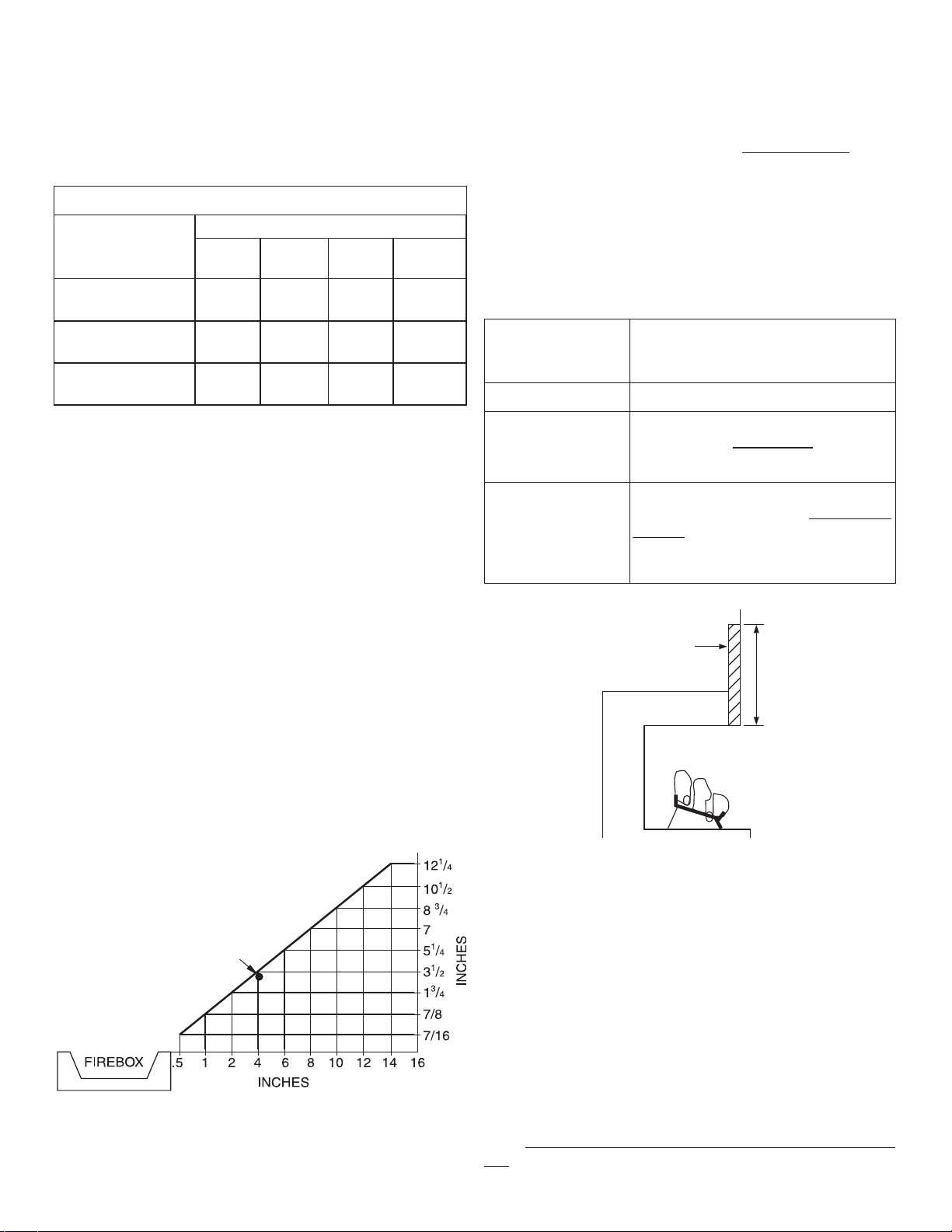
LOG SIZING REQUIREMENTS
Log
Size
LMF24GTA/B
LMF24MOA/B
LMF30GTA/B
LMF30MOA/B
LMF36GTA/B
LMF36MOA/B
Height Depth
Minimum Firebox Size
Front
Width
29" 15.5" 32.5" 22.75"
29" 15.5" 39" 26.75"
29'' 20'' 47'' 33''
Rear*
Width
Minimum Noncombustible Material Clearances
If Not Using Mantel
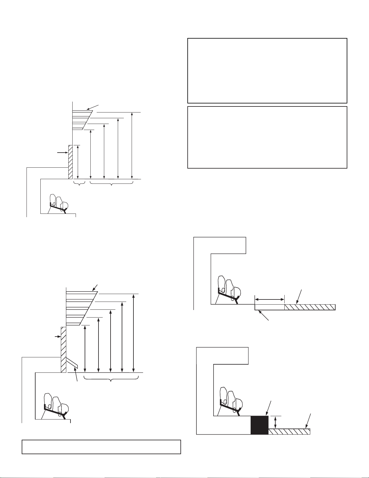
NOTE: If using a mantel proceed to If Using Mantel. If not
using a mantel, follow these instructions.
You must have noncombustible material(s) above the fi replace
opening. Noncombustible materials (such as slate, marble, tile,
etc.) must be at least 1/2" thick. With sheet metal, you must
have noncombustible material behind it. Noncombustible
material must extend at least 8" up (for all models). If noncombustible material is less than 12", you must install the fi replace
hood accessory. See Figure 3 for minimum clearances.
Noncombustible
Requirements for Safe Installation
Material Distance
(A)
1
2" or more Noncombustible material OK.
* When optional MFEB (MAGNIFLAME EMBER BURNER KIT) is
used with these burner systems, the minimum fi rebox sizes are
different. See MFEB instructions for minimum fi rebox sizes if this
accessory is used.
Carefully follow the instructions below. This will ensure safe
installation into a masonry, UL127-listed manufactured fi re-
place or listed outdoor fi rebox.
Minimum Clearances For Side Combustible Material,
Side Wall and Ceiling
A. Clearances from the side of the fi replace cabinet to any
combustible material and wall should follow diagram in
Figure 2.
Example: The face of a mantel, bookshelf, etc. is made of
combustible material and protrudes 3-1/2" from the wall.
This combustible material must be 4" from the side of the
fi replace cabinet (see Figure 2).
NOTE: When installing your gas logs into a manufactured
fi rebox, follow fi rebox manufacturer’s instructions for mini-
mum clearances to combustible materials.
B. Clearances from the top of the fi replace opening to the ceil-
ing should not be less than 42".
Example
*
*Minimum 16" from Side Wall
Figure 2 - Minimum Clearance for Combustible to Wall
Between 8" and 12"
Install fi replace hood accessory
(GA6050 - see Accessories, Page 23).
Less than 8"
Noncombustible material must be ex-
tended to at least 8". See Between 8"
and 12", above. If you cannot extend
material, you must operate appliance
with fl ue damper open.
Heat Resistant
Material
(A)
Figure 3 - Heat Resistant Material (Slate, Marble, Tile,
etc.) Above Fireplace
If Using Mantel
Y ou must have noncombustible material(s) above the fi replace
opening. Noncombustible materials (such as slate, marble,
tile, etc.) must be at least 1/2" thick. With sheet metal, you
must have noncombustible material behind it. Noncombustible material must extend at least 8" up (for all models). If
noncombustible material is less than 12", you must install the
fi replace hood accessory. Even if noncombustible material is
more than 12", you may need the hood accessory to defl ect
heat away from your mantel shelf. See Figure 3 and Figures
4 and 5, Page 6, for minimum clearances.
IMPORTANT: If you cannot meet these minimum clearances,
you must operate appliance with chimney fl ue damper open.
Go to Installing Damper Clamp Accessory for V ented Opera-
tion, Page 7.
900465-01A 5
SuperiorFireplaces.us.com
Page 6
INSTALLATION
Continued
MANTEL CLEARANCES
In addition to meeting noncombustible material clearances,
you must also meet required clearances between fi replace
opening and mantel shelf. If you do not meet the clearances
listed below, you will need a hood.
Determining Minimum Mantel Clearance
If you meet minimum clearance between mantel shelf and
top of fi replace opening, a hood is not required (see Figure
4, Page 6).
Minimum NonCombustible
Material
10"
8"
6"
2
1
/2
"
(A)
12"
Mantel Shelf
18" 20" 22" 24"
Underside of
Mantel Shelf
All minimum
distances are
in inches
NOTICE: Surface temperatures of adjacent
walls and mantels become hot during operation. Walls and mantels above the fi rebox may
become hot to the touch. If installed properly,
these temperatures meet the requirement of the
national product standard. Follow all minimum
clearances shown in this manual.
NOTICE: If your installation does not meet the
minimum clearances shown, you must do one
of the following:
• operate the logs only with the fl ue damper
open
• raise the mantel to an acceptable height
• remove the mantel
Top of Fireplace
Minimum NonCombustible
Material Height
Distances to
Underside of
Mantel
Opening
Figure 4 - Minimum Mantel Clearances Without Using Hood
Determining Minimum Mantel Clearance When Using a
Hood
If minimum clearances in Figure 4, are not met, you must have
a hood. When using a hood there are still certain minimum
mantel clearances required. Follow minimum clearances
shown in Figure 5, when using hood.
Mantel Shelf
8"
12" 15" 18" 20"
Min.
Underside
of Mantel
Shelf
Minimum
Noncombustible
Material
12"
10"
8"
6"
2
1
/2
"
FLOOR CLEARANCES
A. If installing appliance on the fl oor level, you must maintain the
minimum distance of 14" to combustibles (see Figure 6).
B. If combustible materials are less than 14" to the fi replace,
you must install appliance at least 5" above the combustible
fl ooring (see Figure 7).
Combustible
14"
Material
Min.
Noncombustible Material
Figure 6 - Minimum Fireplace Clearances If Installed at
Floor Level
Top of
Fireplace
Opening
Figure 5
Hood (GA6050
or GA6053)
Distances to
Underside of
Mantel
- Minimum Mantel Clearances When Using Hood
Minimum clearance requirements include any projections such as shelves, window
sills, mantels, etc. above the appliance.
6
SuperiorFireplaces.us.com
Hearth
Combustible
Material
5"
Min.
Figure 7 - Minimum Fireplace Clearances Above
Combustible Flooring
900465-01A
Page 7
INSTALLATION
Continued
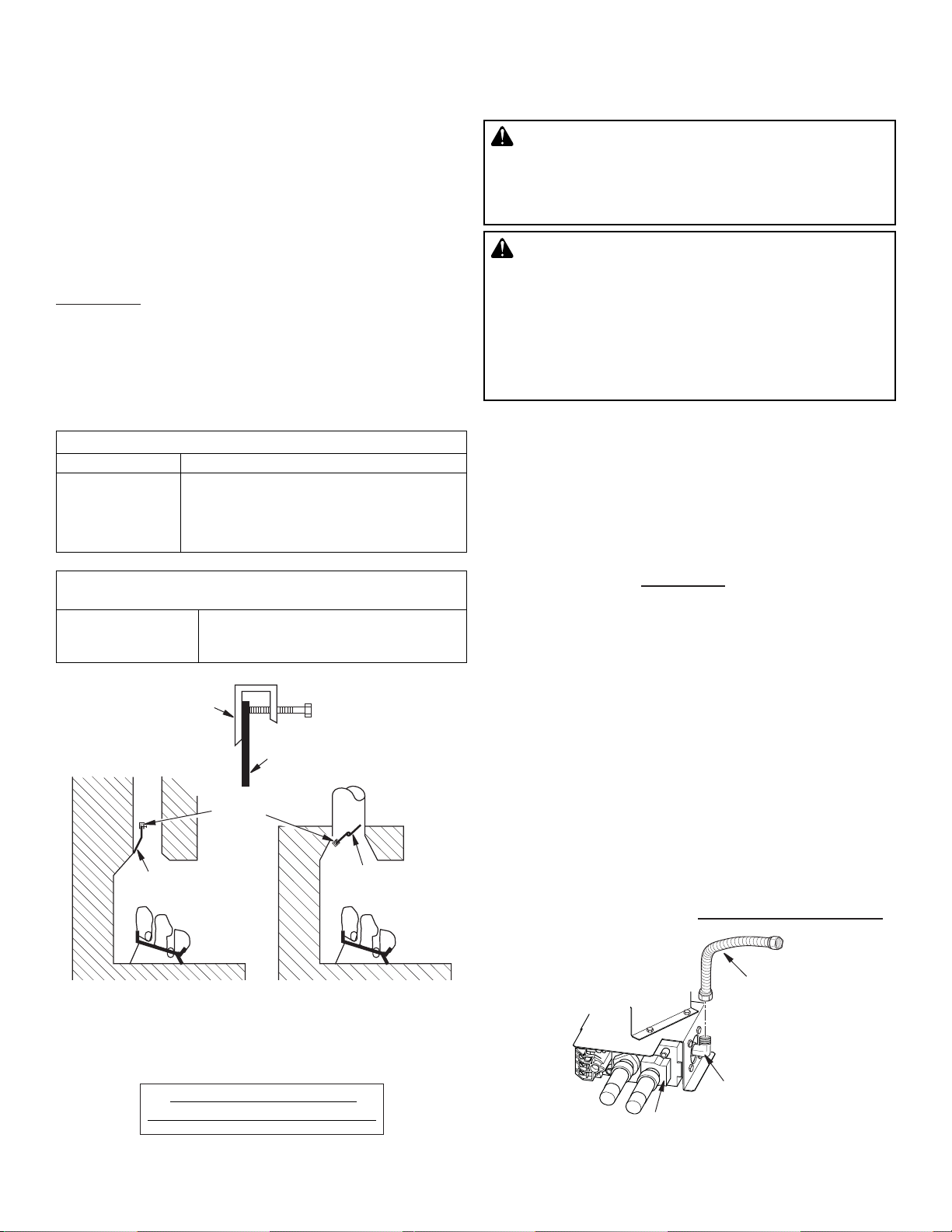
INSTALLING DAMPER CLAMP ACCESSORY FOR
VENTED OPERATION
NOTE: When used as a vented indoor appliance, appliance
must be installed only in a solid-fuel-burning fi replace with
a working fl ue and constructed of noncombustible material.
For Massachusetts Residents Only: Installation of this gas
log set as a vented indoor appliance in the Commonwealth of
Massachusetts requires the damper be permanently removed
or welded in the fully open position.
You must install the damper clamp accessory (to order, see
Accessories, Page 23). This will ensure vented operation
(see Figure 8). The damper clamp will keep damper open.
Installation instructions are included with clamp accessory.
See chart below for minimum permanent fl ue opening you
must provide. Attach damper clamp so the minimum permanent fl ue opening will be maintained at all times.
INST ALLING APPLIANCE BASE ASSEMBL Y
W ARNING: Y ou must secure this appliance
to fi replace fl oor. If not, appliance will move
when you adjust controls. Moving appliance
may cause a gas leak.
WARNING: If installing in a sunken fi replace,
special care is needed. You must raise the fi re-
place fl oor to allow access to appliance control
panel. This will ensure adequate air fl ow and
guard against sooting and controls being damaged. Raise fi replace fl oor with noncombustible
material. Make sure material is secure.
Area of Various Standard Round Flues
Diameter Minimum Required Area
5" 20 sq. inches
6" 29 sq. inches
7" 39 sq. inches
8" 51 sq. inches
Chimney Height Minimum Permanent Flue Opening
6' to 15' 39 sq. inches
15' to 30' 29 sq. inches
Damper
Clamp
Damper
Damper
Clamp
Damper
Damper
Installation Items Needed
• hardware package (provided with appliance)
• approved fl exible gas hose and fi ttings provided (if allowed
by local codes)
• sealant (resistant to propane/LP gas, not provided)
• electric drill with 3/16” masonry drill bit
NOTE: Install optional MRC Series receiver and hand-held
remote control kit (see Accessories, Page 23) before install-
ing gas log appliance. See installation instructions included
with the kit.
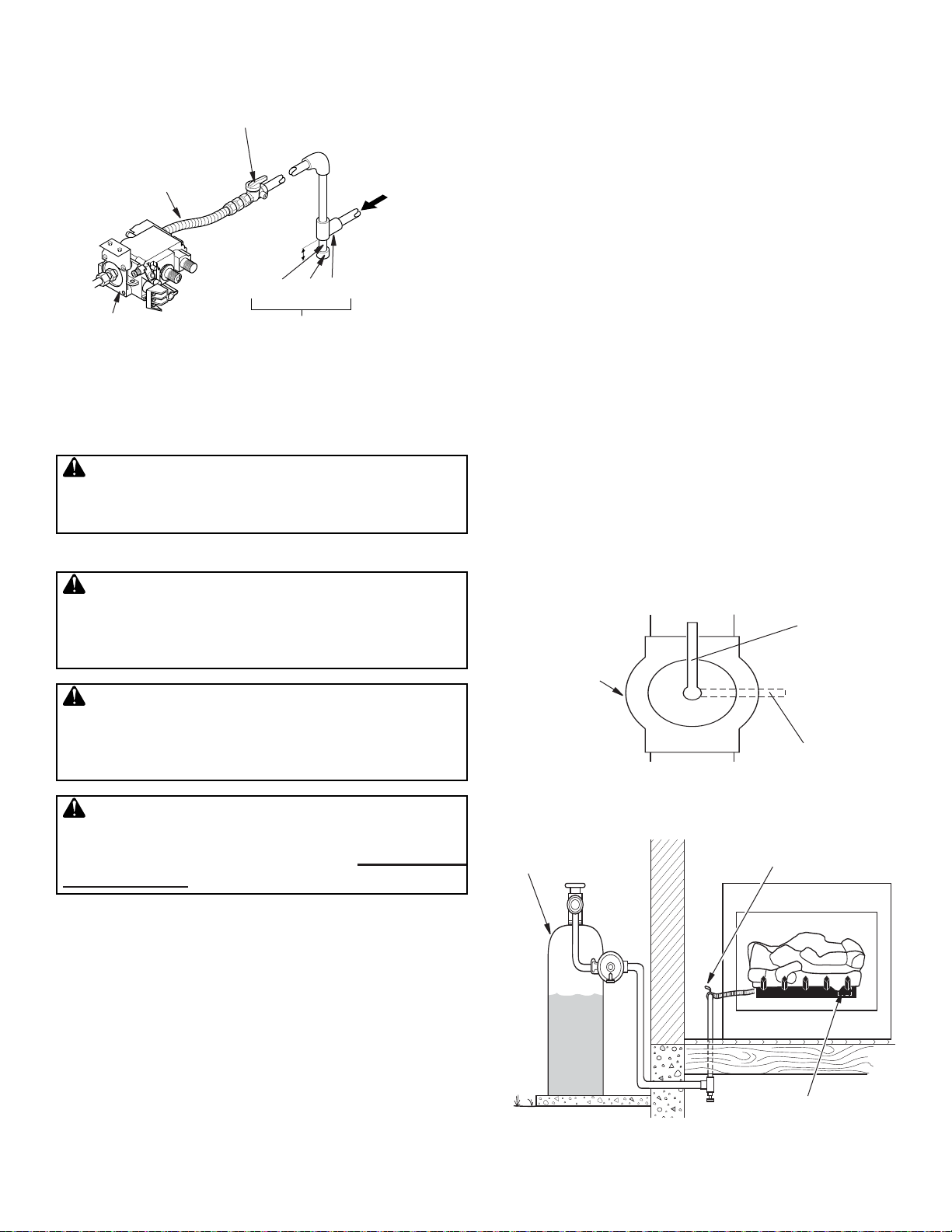
1. Apply pipe joint sealant lightly to male threads of the 1/2
NPT side of gas fi tting elbow (provided) and connect to inlet
side of gas control. Remove gas fi tting from fl exible gas
hose (provided) before connecting to elbow (see Figure
9).
2. Position appliance base assembly in fi replace.
3. Mark screw locations through holes in front panel of base
(see Figure 10, Page 8). If installing in a brick-bottom
fi replace, mark screw locations in mortar joint of bricks.
4. Remove appliance base from fi replace.
5. Drill holes at marked locations using 3/16" drill bit.
6. Attach base, through holes in back side panels of base, to
fi replace fl oor using masonry screws provided in hardware
package (see Figure 10, Page 8).
7. Connect to gas supply. See Connecting To Gas Supply.
Masonry Fireplace
Figure 8 - Attaching Damper Clamp
WARNING: DO NOT INSTALL IN
SLEEPING ROOM OF MOBILE HOMES.
900465-01A 7
Manufactured Fireplace
Gas Control
Figure 9 - Attaching Flexible Gas Hose to Appliance
Gas Regulator
SuperiorFireplaces.us.com
Flexible Gas Hose
(Provided with VGC
Series Models Only)
(Install if allowed by
local codes)
Elbow, 1/2 NPT x
3/8 Flare
Page 8
INSTALLATION
Continued
Masonry Screw
Figure 10 - Attaching Base to Fireplace Floor
(Model Shown May Vary from Actual Model)
CONNECTING TO GAS SUPPLY
WARNING: This appliance requires a 1/2"
NPT (National Pipe Thread) inlet connection
to the pressure regulator.
WARNING: A qualifi ed service person must
connect appliance to gas supply. Follow all
local codes.
CAUTION: Never connect propane/LP appliance directly to the propane/LP supply.
This appliance requires an external regulator
(not supplied). Install the external regulator
between the appliance and propane/LP supply .
WARNING: Never connect natural gas appliance to private (non-utility) gas wells. This
gas is commonly known as wellhead gas.
Installation Items Needed
Before installing appliance, make sure you have the items
listed below.
• external regulator (supplied by installer)
• piping (check local codes)
• sealant (resistant to propane/LP gas)
• equipment shutoff valve *
• test gauge connection *
• sediment trap
• tee joint
• pipe wrench
• approved fl exible gas line with gas connector (if allowed by
local codes) (not provided
* An equipment shutoff valve with 1/8" NPT tap is an acceptable alternative to test gauge connection. Purchase the
optional equipment shutoff valve from your dealer.
8
)
SuperiorFireplaces.us.com
For propane/LP units, the installer must supply an external
regulator. The external regulator will reduce incoming gas
pressure. Y ou must reduce incoming gas pressure to between
1 1" and 14" of water . If you do not reduce incoming gas pressure, appliance regulator damage could occur. Install external
regulator with the vent pointing down as shown in Figure 1 1.
Pointing the vent down protects it from freezing rain or sleet.
CAUTION: Use only new, black iron or
steel pipe. Internally-tinned copper tubing
may be used in certain areas. Check your
local codes. Use pipe of 1/2" diameter or
greater to allow proper gas volume to appliance. If pipe is too small, undue loss of volume
will occur.
Installation must include an equipment shutoff valve, union
and plugged 1/8" NPT tap. Locate NPT tap within reach for
test gauge hook up. NPT tap must be upstream from appliance (see Figure 12, Page 9).
IMPORTANT: Install equipment shutoff valve in an acces-
sible location. The equipment shutoff valve is for turning on
or shutting off the gas to the appliance.
Check your building codes for any special requirements for
locating equipment shutoff valve to appliances.
Apply pipe joint sealant lightly to male NPT threads. This will
prevent excess sealant from going into pipe. Excess sealant
in pipe could result in clogged appliance valves.
WARNING: Use pipe joint sealant that is
resistant to liquid petroleum (LP) gas.
We recommend that you install a sediment trap in supply
line as shown in Figure 12. Locate sediment trap where it is
within reach for cleaning. Install in piping system between fuel
supply and appliance. Locate sediment trap where trapped
matter is not likely to freeze. A sediment trap traps moisture
and contaminants. This keeps them from going into appliance
controls. If sediment trap is not installed or is installed wrong,
appliance may not run properly.
Propane/LP
Supply Tank
Figure 11 - External Regulator With Vent Pointing Down
External
Regulator
with Vent
Pointing
Down
900465-01A
Page 9
INSTALLATION
Continued
Equipment Shutoff Valve
With 1/8" NPT Tap*
Approved Flexible
Gas Hose (if allowed
by local codes)
Gas Control
3" Minimum
Pipe Cap Tee
Nipple Joint
Sediment Trap
PROPANE/LP
From External
Regulator
(11" W.C.**
to 14" W.C.
Pressure)
NATURAL
From Gas
Meter
(5" W.C.**
to 10.5"
W.C.
Pressure)
Figure 12 - Gas Connection
* Purchase the optional equipment shutoff valve from your
dealer.
**Minimum inlet gas supply pressure for purpose of input
adjustment.
CAUTION: Avoid damage to gas control.
Hold gas control with wrench when connecting it to gas piping and/or fi ttings.
CHECKING GAS CONNECTIONS
W ARNING: Test all gas piping and connec-
tions, internal and external to unit, for leaks
after installing or servicing. Correct all leaks
at once.
WARNING: Never use an open fl ame to
check for a leak. Apply a noncorrosive leak
detection fl uid to all joints. Bubbles forming
show a leak. Correct all leaks at once.
5. Correct all leaks at once.
6. Reconnect appliance and equipment shutoff valve to gas
supply. Check reconnected fi ttings for leaks.
Test Pressures Equal To or Less Than 1/2 PSIG (3.5 kPa)
1. Close equipment shutoff valve (see Figure 13).
2. Pressurize supply piping system by either opening propane/LP supply tank valve for propane/LP gas or opening
main gas valve located on or near gas meter for natural
gas or using compressed air.
3. Check all joints from gas meter to equipment shutoff valve
for natural gas or propane/LP supply to equipment shutoff
valve for propane/LP (see Figure 14 or Figure 15, Page
10). Apply noncorrosive leak detection fl uid to all joints.
Bubbles forming show a leak.
4. Correct all leaks at once.
PRESSURE TESTING APPLIANCE GAS
CONNECTIONS
1.
Open equipment shutoff valve (see Figure 13).
2. Open main gas valve located on or near gas meter for
natural gas or open propane/LP supply tank valve.
3. Make sure control knob of appliance is in the OFF position.
4. Check all joints from gas meter to equipment shutoff valve
for natural gas or propane/LP supply to equipment shutoff
valve for propane/LP (see Figure 14, Page 9 or Figure
15, Page 10). Apply noncorrosive leak detection fl uid to all
joints. Bubbles forming show a leak.
Open
Equipment
Shutoff
Valve
Closed
Figure 13 - Equipment Shutoff Valve
CAUTION: Make sure external regulator has
been installed between propane/LP supply and
appliance. See guidelines under Connecting
to Gas Supply, Page 8.
PRESSURE TESTING GAS SUPPLY PIPING SYSTEM
Test Pressures In Excess Of 1/2 PSIG (3.5 kPa)
1. Disconnect appliance with its appliance main gas valve
(control valve) and equipment shutoff valve from gas supply
piping system. Pressures in excess of 1/2 psig will damage
appliance regulator.
2. Cap off open end of gas pipe where equipment shutoff
valve was connected.
3. Pressurize supply piping system by either opening propane/LP supply tank valve for propane/LP gas or opening
main gas valve located on or near gas meter for natural
gas or using compressed air.
4. Check all joints of gas supply piping system. Apply noncorrosive leak detection fl uid to all joints. Bubbles forming show
a leak.
900465-01A 9
SuperiorFireplaces.us.com
Propane/LP
Supply Tank
Equipment
Shutoff Valve
Control Valve
Location
Figure 14- Checking Gas Joints (Propane/LP Only)
Page 10
INSTALLATION
Continued
Equipment Shutoff Valve
Gas Meter
Control Valve
Location
Figure 15 - Checking Gas Joints (Natural Gas Only)
5. Correct all leaks at once.
6. Light appliance (see Operation, Page 15). Check all other
internal joints for leaks.
7.
Turn off appliance (see To Turn Off Gas to Appliance, Page
15 for Remote Ready models).
INSTALLING SWITCH
The AUTO/OFF/ON switch for this log set is installed into
the small single log accompanying this log set. This switch
needs to be used only if remote or wall switch is not being
used.
Connect the wires to the valve from the switch assembly as
shown in Figure 16.
INSTALLING OPTIONAL REMOTE ACCESSORIES
Installing Remote Receiver
Remote control accessories are available separately (see
Accessories, Page 23). Read instructions shipped with re-
mote control along with instructions below before attempting
installation.
1. If unit is already installed in fi replace, continue with these
instructions. If unit has not been installed in fi replace, go
to step 6 and continue installation of remote accessory.
W ARNING: Turn off appliance and let cool
before handling any part of appliance. Make
sure gas is turned of to unit.
2. Carefully remove logs and set aside.
3. Locate mounting screws on sides of appliance base assembly and remove screws. Set screws aside for reinstallation.
4. Disconnect gas line from appliance base as shown in
Figure 9, Page 7.
WARNING: A qualifi ed service person must
connect and disconnect gas to appliance. Follow all local codes.
5. Remove appliance base from fi replace.
6. If installed, disconnect AUTO/OFF/ON switch wire from
control valve at TPTH and TH locations (see Figure 17).
7. Connect wires from hardware pack (with remote receiver
bracket) to control valve at the TPTH and TH locations as
shown in Figure 17. Connect other ends of these wires
to remote receiver wires.
NOTE: Make sure excess wire does not interfere with
burner or pilot.
8.
If appliance was removed from fi replace before installation
of remote accessory, see Installing Appliance Base As-
sembly on Page 7 to reinstall appliance into fi replace. Test
gas connection for leaks (see Checking Gas Connections,
Page 9).
9. If logs were removed from appliance for install remote accessory, replace logs (see Installing Logs, and Volcanic
Stone, Page 11).
10.Place remote receiver on fi replace fl oor next to control
valve. Make sure the remote receiver and wires are not on
or touching either gas burner on the log set.
Installing Batteries for Remote Receiver and Hand Held
Remote Control
Follow instructions accompanying remote control accesory
to install batteries.
NOTE: Only use alkaline batteries.
10
Control Valve
Figure 16 - Connecting Wires
To OFF
Terminal on
Switch
T o AUTO
Terminal
on Switch
SuperiorFireplaces.us.com
900465-01A
Page 11

Control
Valve
INSTALLATION
Continued
Switch
Burner
Tube
Right Front Log
(D-061, D-019 or D027)
Grate Finger
Figure 17- Disconnecting Switch from Control Valve
INSTALLING LOGS AND VOLCANIC STONE
WARNING: Failure to position the parts in
accordance with these diagrams or failure to
use only parts specifi cally approved with this
appliance may result in property damage or
personal injury.
CAUTION: After installation and periodically
thereafter, check to ensure that no fl ame comes
in contact with any log. With appliance set to
Hi, check to see if fl ames contact any log. If
so, reposition logs according to log installation
instructions in this manual. Flames contacting
logs will create soot.
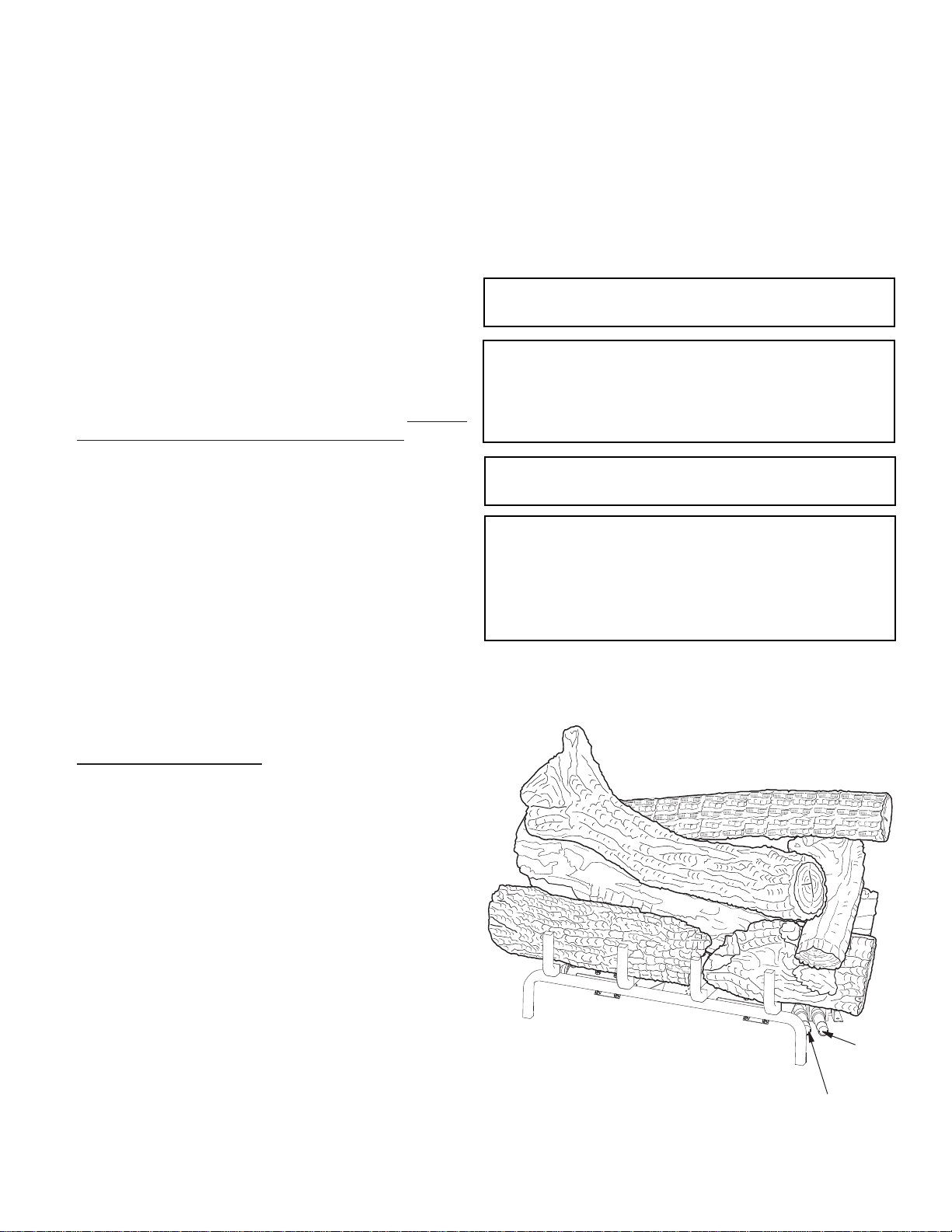
LOG PLACEMENT
It is very important to install these logs exactly as instructed.
Do not modify logs. Only use logs supplied with appliance.
NOTE: Each log includes an identifying number cast in the
log. Look at each log when placing them on the burner system
to be certain it is correct.
Figure 18 - Installing Right Front Log
Round Tube
Burner
Grate Finger
Figure 18A - Installing Right Front Log, Top View
Burner Tube Square Grate
1. Find the right front log (LMF24GTA/B or LMF24MOA/B
models: D-061, LMF30GTA/B or LMF30MOA/B models:
D-019, LMF36GTA/B or LMF36MOA/B models: D-027).
See Figures 18, 18A, 18B, and 18C for reference. The log
has a rectangular shape on the bottom that fi ts against the
lip on the black metal base, the square grate, and the round
tube burner. Slide the log in place as shown in Figures.
Figure 18B - Installing Right Front Log, Top View
900465-01A 11
SuperiorFireplaces.us.com
Page 12

INSTALLATION
Continued
Figure 18C - Installing Right Front Log, Side View
2. Find the back left log (LMF24GTA/B or LMF24MOA/B
models: D-060, LMF30GTA/B or LMF30MOA/B models:
D-018, LMF36GTA/B or LMF36MOA/B models: D-026).
See Figures 19, 19A, and 19B. Figure 19A shows how
the log must fi t against the end of the burner. Figure 19B
shows how the notch in log fi ts against the vertical portion
of the burner tube. Place this log on the base assembly by
inserting it from the left side as shown in Figure 19. Y ou will
need to twist the log slightly to get it to fi t against the burners
properly . It will rest even with the back edge of the pan.
Vertical Portion of Burner Tube
Figure 19B - Installing Back Left Log (D-018) Rear View
3. Find the front left log (LMF24GTA/B or LMF24MOA/B models: D-059, LMF30GT A/B or LMF30MOA/B models: D-017,
LMF36GT A/B or LMF36MOA/B models: D-025). See Figures
20, 20A, and 20B. The log has a rectangular stand off on
the bottom that fi ts against the lip on the black metal base as
shown in Figure 20A, Page 12. The bottom of this log has
a slot that fi ts over the second bar on the grate as shown in
Figure 20B, Page 13. Place the log on the base assembly
as shown in fi gures.
Front Left Log (D-059,
D-017 or D025)
Back Left Log (D-060,
D-018 or D026)
Log Notch
Figure 19 - Installing Back Left Log
Log Notch
Burner Tube
Flat Part of Log
Burner Tube
Grate Fingers
Figure 20 - Installing Front Left Log
12
Figure 19A - Installing Back Left Log
SuperiorFireplaces.us.com
Figure 20A - Installing Front Left Log Side View
900465-01A
Page 13

INSTALLATION
Continued
Square Grate
Log Notch
Grate Finger
Log Slot
Figure 20B - Installing Front Left Log
4. Find the charred log (D-020). See Figures 21, 21A, and
21B. The log has a slot in the bottom that fi ts over the square
grate and rests against the burner tube as shown in Figure
21. Place this log on the base as shown in fi gures.
D020
Charred Log
Log Notch
Right Front Log
Figure 21B - Installing Charred Log Top Side View
5. Find the middle split log (LMF24GT A/B or LMF24MOA/B
models: D-063, LMF30GTA/B or LMF30MOA/B models:
D-021, LMF36GTA/B or LMF36MOA/B models: D-028).
See Figures 22 and 22A. The split side of the log faces
forward. The log has a notch that fi ts around the burner tube
on the right side. The left side of the burner tube fi ts into the
notch on the back side of this log. The log is placed properly
when it sits parallel to the tube burner and the square peg is
pointing up. See Figures for reference.
Square Peg
Middle Split Log (D-063,
D-021 or D028)
Figure 22 - Installing Middle Split Log (D-021)
Figure 21 - Installing Charred Log
Figure 21A - Installing Charred Log Top View
Figure 22A - Installing Middle Split Log Rear Top Side
Log Notch Burner Tube
View
900465-01A 13
SuperiorFireplaces.us.com
Page 14

INSTALLATION
Continued
6. Find the right split crossover log (D-022) The bottom of the
log has a rectangular stand off that fi ts in the slots on the right
side of the front right log and the middle split log. Place this
log as shown in Figure 23.
Square Peg
Right Front Log
Figure 23 - Installing Right Split Crossover Log
7. For GTA/GTB logs, fi nd the front top log (D-024). See Figure
24. The left end of this log has a square hole that fi ts over a
square peg that is on the top of the middle split log. The right
end of this log rests behind the knot on the top of the front
right log.
Right Split Crossover
Log (D-022)
Back Top Log
(D-062, D-023 or D029)
Right Split
Crossover
Log (D-022)
Figure 25 - Installing Back Top Log and Final Assembly
Front Top Log
(D-024)
Rectangular
Peg
Middle Split Log
Right Split
Crossover
Log (D-022)
Figure 24 - Installing Front Top Log
8. Find the back top log (LMF24GTA/B or LMF24MOA/B
models: D-062, LMF30GTA/B or LMF30MOA/B models:
D-023, LMF36GTA/B or LMF36MOA/B models: D-029).
See Figures 25, and 25A. The left end of this log has a round
hole that fi ts over the round peg that is on the top of the back
left log. The right end of this log has a rectangular hole that
fi ts over the rectangular peg on the top of the right crossover
log.
VOLCANIC STONE PLACEMENT
Place Volcanic Stone around the base of the burner assembly
on the fi replace fl oor to simulate an ash bed. Do not place
Volcanic Stone or any other material on the burner.
Figure 25A - Installing Back Top Log, Top View
D-080
Front Top
Left
D-081
Front Top
Right
Figure 26 - Installing Small Left Hand And
Right Hand Logs
For MOA/B logs only, follow steps 9 and 10.
9. Install the small Left Top Log D080 as shown in Figure 26
by mating the rectangular peg and notch.
10. Install the small Right T op Log D081 as shown in Figure 26.
14
SuperiorFireplaces.us.com
900465-01A
Page 15

OPERATION
FOR YOUR SAFETY
READ BEFORE LIGHTING
WARNING: If you do not follow these instruc-
tions exactly, a fi re or explosion may result
causing property damage, personal injury or
loss of life.
A. This appliance has a pilot which must be lighted with
a piezo igniter. When lightning the pilot, follow these
instructions exactly.
B. BEFORE LIGHTING smell all around the appliance area
for gas. Be sure to smell next to the fl oor because some
gas is heavier than air and will settle on the fl oor.
WHAT TO DO IF YOU SMELL GAS
• Do not try to light any appliance.
• Do not touch any electric switch; do not use any
phone in your building.
• Immediately call your gas supplier from a neighbor’s
phone. Follow the gas supplier’s instructions.
• If you cannot reach your gas supplier, call the fi re
department.
C. Use only your hand to push in or turn gas control knob.
Never use tools. If the knob will not push in or turn by
hand, do not try to repair it, call a qualifi ed technician.
Force or attempted repair may result in a fi re.
D. Do not use this appliance if any part has been under water.
Immediately call a qualifi ed service technician to inspect
the appliance and to replace any part of the control system and any gas control which has been under water.
LIGHTING
INSTRUCTIONS
1. STOP! Read the safety information, above.
2. Make sure switch is in the OFF position.
3. Be sure gas line shut-off valve is OPEN.
4.
Press in and turn control knob clock wise to the
OFF position (see Figure 27).
NOTE: Knob cannot be turned from PILOT to OFF unless
knob is pushed in slightly. DO NOT FORCE.
5. Wait fi ve (5) minutes to clear out any gas. If you then smell
gas, STOP! Follow "B" in the safety information in column
1. If you don't smell gas, go on the next step.
6. Press in and turn control knob coun ter clock wise
to the PILOT po si tion. Press in control knob for fi ve (5)
seconds
7. With control knob pressed in, press and release igniter
button. This will light pilot. If needed, keep press ing igniter
button until pilot lights.
NOTE: If pilot does not stay lit, con tact a qualifi ed service
person or gas sup pli er for repairs.
8. Keep control knob pressed in for 30 seconds after lighting
pilot. After 30 seconds, release control knob.
• If control knob does not pop out when released, turn off
gas supply and contact a qualifi ed ser vice person or gas
supplier for re pairs.
NOTE: If pilot goes out, repeat steps 4 through 8.
(see Figure 27)
.
9. Slightly push in and turn control knob counterclockwise
to the ON position.
10.Wait one minute and move switch to the ON po si tion to
light burner.
NOTE: AUTO is only func tion al when using optional remote
control accessory.
11. Set fl ame adjustment knob to any lev el be tween HI and LO.
TO TURN OFF GAS
TO APPLIANCE
1. Turn control knob clockwise to the OFF position.
2a. Set switch in the OFF position.
2b. If Using Optional Hand-Held Remote: Set selector
switch in the OFF position to prevent draining battery.
3. Close equipment shutoff valve (see Figure 13, Page 9).
MANUAL LIGHTING
PROCEDURE
1. Follow steps 1 through 6 under Lighting Instructions.
2. Press control knob and light pilot with match.
3. Keep control knob pressed in for 30 seconds after lighting pilot. After 30 seconds, release control knob. Now
follow steps 9 through 11, under Lighting Instructions.
OPTIONAL HAND-HELD
REMOTE OPERATION
NOTE: All remote control accessories must be purchased
separately (see Accessories, Page 23). Follow instructions
included with the remote control.
NOTICE: You must light the pilot before using
the hand-held remote control unit. See Lighting
Instructions.
After lighting, let pilot fl ame burn for about one minute. Turn
control knob to ON position. Adjust fl ame adjustment knob
anywhere between HI and LO. Slide the selector switch to
the REMOTE position (see Figure 27).
Control
Selector
Switch
Figure 27 - Control Knob, Igniter Button and Remote
NOTE: The burner may light if hand-held remote was on when
selector switch was last turned off. You can now turn burner
on and off with hand-held remote control unit.
IMPORTANT: Do not leave selector switch in the REMOTE
or ON position when pilot is not lit. This will drain the battery.
Igniter
Flame Adjustment
Knob
Selector Switch
Knob in OFF
Position
900465-01A 15
SuperiorFireplaces.us.com
Page 16

INSPECTING BURNERS
Check pilot fl ame pattern and burner fl ame patterns often.
PILOT ASSEMBL Y
The pilot assembly is factory preset for the proper fl ame height.
Alterations may have occurred during shipping and handling.
Call a qualifi ed service person to readjust the pilot if necessary .
The height of the thermopile must be 3/8" to 1/2" above the
pilot fl ame as shown in Figure 28. The thermocouple must be
at a height of about 1/8" above the pilot fl ame. The fl ame from
the pilot burner must extend beyond both the thermocouple
and thermopile.
If your pilot assembly does not meet these requirements:
• turn fi replace off (see To Turn Off Gas to Appliance, Page
15)
• see Troubleshooting, Page 19
BURNER FLAME PATTERN
Thermopile
3/8" to 1/2"
Pilot Burner
1/8"
Thermocouple
Dark Orange
Flames
Figure 30 - Incorrect Burner Flame Pattern
CLEANING AND MAINTENANCE
W ARNING: Turn off appliance and let cool
before cleaning.
CAUTION: You must keep control areas,
burners and circulating air passageways of appliance clean. Inspect these areas of appliance
before each use. Have appliance inspected
yearly by a qualifi ed service person.
Piezo
Igniter
Figure 28 - Pilot Assembly
Figure 29 shows correct burner fl ame pattern.
NOTICE: Do not mistake orange fl ames with
yellow tipping. Dirt or other fi ne particles are
burned by appliance, causing brief patches of
orange fl ame.
If burner fl ame pattern is incorrect, as shown in Figure 30.
• turn appliance off (see To Turn Off Gas to Appliance, Page
15)
• see Troubleshooting, Page 19
Yellow Flames with
Orange Streaks
Figure 29 - Correct Burner Flame Pattern
WARNING: Failure to keep the primary air
opening(s) of the burner(s) clean may result
in sooting and property damage.
BURNER INJECTOR HOLDER AND PILOT AIR
INLET HOLE
The primary air inlet holes allow the proper amount of air to
mix with the gas. This provides a clean burning fl ame. Keep
these holes clear of dust, dirt, lint and pet hair. Clean these air
inlet holes prior to each heating season. Blocked air holes will
create soot. We recommend that you clean the unit every three
months during operation and have appliance inspected yearly
by a qualifi ed service person.
We also recommend that you keep the burner tube and pilot
assembly clean and free of dust and dirt. T o clean these parts
we recommend using compressed air no greater than 30 PSI.
Y our local computer store, hardware store or home center may
carry compressed air in a can. If using compressed air in a
can, please follow the directions on the can. If you don’t follow
directions on the can, you could damage the pilot assembly.
1. Shut off unit, including pilot. Allow unit to cool for at least
thirty minutes.
2. Inspect burner, pilot and primary air inlet holes on injector
holder for dust and dirt (see Figure 31, Page 17).
3. Blow air through the ports/slots and holes in the burner.
4. Check injector holder located at end of burner tube again.
Remove any large particles of dust, dirt, lint or pet hair with
a soft cloth or vacuum cleaner nozzle.
5. Blow air into the primary air holes on the injector holder.
16
SuperiorFireplaces.us.com
900465-01A
Page 17

CLEANING AND MAINTENANCE
Continued
6. In case any large clumps of dust have now been pushed
into the burner repeat steps 3 and 4.
Clean pilot assembly also. Additional cleaning may be needed
for proper pilot operation based on use/lack of use. A yellow tip
on the pilot fl ame may indicate dust and dirt in the pilot assem-
bly. There is a small pilot air inlet hole about from where the
pilot fl ame comes out of pilot assembly (see Figure 32). With
unit off, lightly blow air through air inlet hole. You may blow
through a drinking straw if compressed air is not available.
Injector
Holder
Burner Tube
Primary Air
Inlet Holes
Figure 31 - Injector Holder On Outlet Burner Tube
LOGS
• If you remove logs for cleaning, refer to Installing Logs and
Volcanic Stone, Page 11, to properly replace logs.
• Replace log(s) if broken or chipped (dime-sized or larger).
MAIN BURNER
Periodically inspect all burner fl ame holes with appliance running.
All slotted burner fl ame holes should be open with fl ame present.
All round burner fl ame holes should be open with a small blue
fl ame present. Some burner fl ame holes may become blocked
by debris or rust, with no fl ame present. If so, turn off appliance
and let cool. Remove blockage, blocked burner fl ame holes will
create soot.
WARNING: The injector holders (air shut-
ters) are not adjustable. Do not move injector
holders from their original positions.
At least once a year, the vent system for the
fi replace in which this appliance is installed
shall be inspected, cleaned, and repaired as
necessary by a qualifi ed service person.
Thermopile
3/8" to 1/2"
Pilot Burner
Thermocouple
Piezo
Igniter
Figure 32 - Pilot Inlet Air Hole
(Your pilot may vary from pilot shown)
1/8"
900465-01A 17
SuperiorFireplaces.us.com
Page 18

SPECIFICATIONS
MNF24ONM AND MNF30ONM
• Rating (Variable): 29,000/40,000 Btu/Hr
• Type Gas: Natural
• Ignition: Electronic
• Manifold Pressure: 3.4" W.C.
• Inlet Gas Pressure (in. of water):
Max - 10.5" W.C., Min* - 5" W.C.
*For purpose of input adjustment
WIRING DIAGRAM (REMOTE READY MODELS)
MNF24OPM AND MNF30OPM
• Rating (Variable): 29,000/40,000 Btu/Hr
• Type Gas: Propane/LP
• Ignition: Electronic
• Manifold Pressure: 7.9" W.C.
• Inlet Gas Pressure (in. of water):
Max - 14" W.C., Min* - 11" W.C.
*For purpose of input adjustment
To Thermopile
To OFF Terminal on
Switch
T o AUT O T erminal on
Switch
18
SuperiorFireplaces.us.com
900465-01A
Page 19

TROUBLESHOOTING
W ARNING: Turn off appliance and let cool before servicing. Only a qualifi ed service person
should service and repair appliance.
NOTE: All troubleshooting items are listed in order of operation.
OBSERVED PROBLEM
When igniter button is pressed, there
is no spark at ODS/pilot
When igniter button is pressed, there
is spark at ODS/pilot but no ignition
POSSIBLE CAUSE
1. Igniter electrode not connected to
igniter cable
2. Igniter cable pinched or wet
3. Broken igniter cable
4. Bad igniter
5. Igniter electrode positioned wrong
6. Igniter electrode broken
7. Battery not installed, battery
power low or battery not installed
correctly (electronic ignition models only)
1. Gas supply turned off or equipment shutoff valve closed
2. Control knob not in PILOT position
3. Control knob not pressed in while
in PILOT position
4.
Air in gas lines when installed
5. Depleted gas supply (propane/
LP only)
6. ODS/pilot is clogged
7. Gas regulator setting is not correct
REMEDY
1. Reconnect igniter cable
2. Free igniter cable if pinched by
any metal or tubing. Keep igniter
cable dry
3. Replace igniter cable
4. Replace igniter
5. Replace pilot assembly
6. Replace pilot assembly
7. Install new alkaline battery in
electronic igniter. Verify battery
is installed correctly
1. Turn on gas supply or open equipment shutoff valve
2. Turn control knob to PILOT position
3. Press in control knob while in
PILOT position
4. Continue holding down control
knob. Repeat igniting operation
until air is removed
5. Contact local propane/LP gas
company
6. Clean ODS/pilot (see Cleaning
and Maintenance, Page 16) or
replace ODS/pilot assembly
7. Replace gas regulator
900465-01A 19
SuperiorFireplaces.us.com
Page 20

TROUBLESHOOTING
Continued
OBSERVED PROBLEM
ODS/pilot lights but fl ame goes out
when control knob is released
POSSIBLE CAUSE
1. Control knob not fully pressed in
2. Control knob not pressed in long
enough
3. Safety interlock system has been
triggered
4. Equipment shutoff valve not fully
open
5. Pilot fl ame not touching thermo-
couple, which allows thermocouple to cool, causing pilot fl ame
to go out. This problem could be
caused by one or both of the following:
A) Low gas pressure
B) Dirty or partially clogged ODS/
pilot
6. Thermocouple connection loose
at control valve
7. Thermocouple damaged
8. Control valve damaged
REMEDY
1. Press in control knob fully
2. After ODS/pilot lights, keep control
knob pressed in 30 seconds
3. Wait one minute for safety interlock system to reset. Repeat
ignition operation
4. Fully open equipment shutoff
valve
5. A) Contact local natural or propane/LP gas company
5 B) Clean ODS/pilot (see Cleaning
and Maintenance, Page 16) or
replace ODS/pilot assembly
6. Hand tighten until snug, then
tighten 1/4 turn more
7. Replace pilot assembly
8. Replace control valve
Burner does not light after pilot is lit
Delayed ignition of burner
Burner backfi ring during combustion
1. Inlet gas pressure is too low
2. Burner orifi ce(s) clogged
3. Thermopile leads disconnected
or improperly connected.
4. Remote selector in OFF position
5. Wire disconnected from gas control
1. Manifold pressure is too low
2. Burner orifi ce clogged
3. Mislocated crossover tube
1. Burner orifi ce is clogged or dam-
aged
2. Damaged burner
3. Gas regulator defective
1. Contact local natural or propane/
LP gas company
2. Clean burner (see Cleaning and
Maintenance, Page 16) or replace
burner orifi ce(s)
3.
Reconnect leads see wiring diagram,
Page 18
4. Put remote selector in ON position
5.
See Wiring Diagram,
1. Contact local natural or propane/
LP gas company
2. Clean burner (see Cleaning and
Maintenance, Page 16) or replace
burner orifi ce(s)
3.
Contact qualifi ed service person
1. Clean burner (see Cleaning and
Maintenance, Page 16) or replace
burner orifi ce
2. Replace damaged burner
3. Replace gas regulator
Page 18
20
SuperiorFireplaces.us.com
900465-01A
Page 21

TROUBLESHOOTING
Continued
OBSERVED PROBLEM
Slight smoke or odor during initial
operation
Appliance produces a whistling
noise when burners are lit
White powder residue forming within
burner box or on adjacent walls or
furniture
POSSIBLE CAUSE
1. Residues from manufacturing
processes and logs curing
1. Turning control knob to HI position
when burners are cold
2. Air in gas line
3. Air passageways on appliance
blocked
4. Dirty or partially clogged burner
orifi ce.
1. When heated, vapors from furniture polish, wax, carpet cleaners,
etc. may turn into white powder
residue
REMEDY
1. Problem will stop after a few hours
of operation
1. Turn control knob to LO position
and let warm up for a minute
2. Operate burners until air is removed from line. Have gas line
checked by local natural or propane/LP gas company
3. Observe minimum installation
clearances (see Pages 4-6)
4. Clean burner (see Cleaning and
Maintenance, Page 16) or replace
burner orifi ce(s)
1. T urn appliance off when using furniture polish, wax, carpet cleaners
or similar products
Remote does not function
Appliance produces a clicking/ticking noise just after burners are lit
or shut off
1. Battery is not installed. Battery
power is low
1. Metal expanding while heating or
contracting while cooling
2. Wire connection loose or wire
broken
1. Replace 9-volt batteries in receiver and hand-held remote
1. This is normal with most appliances. If noise is excessive, contact
qualifi ed service person
2. Check wiring connections (see
wiring diagram, Page 18). Replace wire harness if necessary.
900465-01A 21
SuperiorFireplaces.us.com
Page 22

TROUBLESHOOTING
Continued
WARNING: If you smell gas
• Shut off gas supply.
• Do not try to light any appliance.
• Do not touch any electrical switch; do not use any phone in your building.
• Immediately call your gas supplier from a neighbor’s phone. Follow the gas supplier’s instructions.
• If you cannot reach your gas supplier, call the fi re department.
IMPORTANT: Operating appliance where impurities in air exist may create odors. Cleaning supplies, paint, paint remover,
cigarette smoke, cements and glues, new carpet or textiles, etc., create fumes. These fumes may mix with combustion air
and create odors. These odors will disappear over time.
OBSERVED PROBLEM
Appliance produces unwanted odors
Appliance shuts off in use (pilot
operates)
Gas odor even when control knob
is in OFF position
POSSIBLE CAUSE
1. Appliance burning vapors from paint,
hair spray, glues, cleaners, chemicals,
new carpet, etc. (See IMPORTANT
statement above)
2. Low fuel supply (propane/LP only)
3. Gas leak. See Warning state-
ment at top of page
1. Low line pressure
2.
ODS/pilot is partially clogged
1. Gas leak. See Warning state-
ment at top of page
2. Control valve or gas control defective
REMEDY
1. Open window to ventilate room.
Stop using odor causing products
while appliance is running
2. Refill supply tank (propane/LP
only)
3. Locate and correct all leaks (see
Checking Gas Connections,
Page 9)
1. Contact local natural or propane/
LP gas company
2. Clean ODS/pilot (see Cleaning
and Maintenance, Page 16)
1. Locate and correct all leaks (see
Checking Gas Connections,
Page 9)
2. Replace control valve or gas control
Gas odor during combustion
22
1. Foreign matter between control
valve and burner
2. Gas leak. See Warning state-
ment at top of page
SuperiorFireplaces.us.com
1. T ake apart gas tubing and remove
foreign matter
2. Locate and correct all leaks (see
Checking Gas Connections,
Page 9)
900465-01A
Page 23

ACCESSORIES
Purchase these appliance accessories from your local dealer.
If they can not supply these accessories, contact IHP at SuperiorFireplaces.US.com for referral information. You can also
write to the address listed on the back page of this manual.
Only kits supplied by IHP shall be used in the installation
of this appliance. Use of non-approved accessory/part
kit(s) can result in poor performance and safety hazards.
FIREPLACE HOOD, BLACK
Cat. No. F1764, Model GA6050
For all models. Helps defl ect heat away from mantel
or wall above fi replace. Fits openings 28" to 48" wide.
WALL-MOUNT ON/OFF SWITCH
(REMOTE READY MODELS ONLY)
Cat No. F0245, Model GWMS2
For all models. Allows the gas log appliance to be turned on
and off with a wall switch.
DAMPER CLAMP
Cat No. F1760, Model GA6080
For all models. Permanently opens chimney fl ue damper for
vented operation.
VOLCANIC STONE
Cat. No. 80L42, Model FDVS
For all models. Order when additional volcanic stone
is desired.
MAGNIFLAME ACCESORY LOG KIT
Cat. No. F0252, Model LAMF
MAGNIFLAME EMBER BURNER KIT (optional)
Cat No. F0253, Model MFEB
For wood burning fi replace
.
ON
OFF
RECEIVER AND HAND-HELD REMOTE CONTROL
KIT - MRC (REMOTE READY MODELS ONLY)
Cat No. F1077, Model MRC
For all models. Allows the fi replace to be turned on and off
by using a hand-held remote control.
900465-01A 23
SuperiorFireplaces.us.com
Page 24

PARTS
REMOTE-READY CONTROL MODELS
MagniFlameOD24NM, MagniFlameOD24PM, MagniFlameOD30NM, MagniFlameOD30PM
Cat. No. Model
F0558 MagniFlameOD24NM
F0560 MagniFlameOD24PM
F0562 MagniFlameOD30NM
F0564 MagniFlameOD30PM
4
16
17
18
24
23
25
22
1
21
20
19
3
15
14
12
10
13
12
2
11
5
9
6
7
8
24
SuperiorFireplaces.us.com
900465-01A
Page 25

PARTS
MNF24ONM, MNF24OPM, MNF30ONM, MNF30OPM
This list contains replaceable parts used in your appliance. When ordering parts, follow the instructions listed under Replace-
ment Parts on Page 28 of this manual.
Only kits supplied by IHP shall be used in the installation of this appliance. Use of non-approved accessory/part
kit(s) can result in poor performance and safety hazards.
KEY
NO. CAT. NO. DESCRIPTION QTY.
1 J6356 Burner Stainless MF • • • • 1
2 --- Base • • • • 1
3 J8175 Bracket Right Burner • • • • 1
4 J8176 Bracket Left Burner • • • • 1
5 J8235 Bracket Remote Valve • • • • 1
6 J6830 Gas Valve, HI-LO (SIT) NG • • 1
J6831 Gas Valve, HI-LO (SIT) LP • • 1
7 J3843 Knob Long Extension (HI-LO) • • • • 1
8 J3842 Knob long Extension (Pilot) • • • • 1
9 J4883 T - Fitting 3/8 Brass Tube • • • • 1
10 J8238 Cap 3/8 Compression • • • • 1
11 J8170 Decal, Caution Label • • • • 1
12 J8236 Leg, Outdoor Base • • • • 2
13 J6532 Grate Stainless MF42 • • 1
J8237 Grate Stainless MF48 • • 1
14 J4596 Igniter, Electric • • • • 1
15 J6144 Bracket, Igniter • • • • 1
16 J5198 Shutter , Air NG • • 1
J5199 Shutter , Air LP • • 1
17 J3604 Orifi ce, 0.12 NG • • 1
J3615 Orifi ce, 0.07 LP • • 1
18 J6127 Orifi ce Holder, 90 Degrees • • • • 1
19 J4733 Nut and Sleeve, Brass Compression • • • • 1
20 J4711 Tube, Flex 3/8 X 15'' • • • • 1
21 J8172 Nut, 10-24 Black Hex • • • • 2
22 J8239 Shield, Pilot • • • • 1
23 J4717 Pilot NG # 51 • • 1
J4118 Pilot LP # 30 • • 1
24 J8173 Screw Black Pan Head PH 10-24 X .75 • • • • 2
25 J5918 Spacer, .4375 Aluminum • • • • 2
MFN24OPM
MFN24ONM
MFN30ONM
MFN30OPM
This list contains replaceable parts used in your appliance. When ordering parts, follow the instructions listed under Replacement Parts below.
PARTS AVAILABLE, NOT SHOWN - ALL MODELS
J3664 Caution Decal 1
J3689 Hardware Kit 1
80L42 Volcanic Stone 1
J5519 Flextube with Fitting 1
J3656 Fan Switch 1
900465-01A 25
SuperiorFireplaces.us.com
Page 26

PARTS
LOG SET MODELS
LMF24GTA/B, LMF30GTA/B AND LMF36GTA/B
This list contains replaceable parts used in your appliance. When ordering parts, follow the instructions listed under Replacement Parts on Page 28 of this manual.
7
8
4
2
5
3
6
1
26
9
KEY
NO. CAT. NO. Log Id. # CAT. NO. Log Id. # CAT. NO. Log Id. # DESCRIPTION QTY.
LMF24GTA/B LMF30GTA/B, LMF36GTA/B
1 J6696 D-061 J6516 D-019 J6527 D-027 Log, Front Right 1
2 J6697 D-060 J6517 D-018 J6528 D-026 Log, Back Left 1
3 J6698 D-059 J6518 D-017 J6529 D-025 Log, Front Left 1
4 J6519 D-020 J6519 D-020 J6519 D-020 Log, Charred 1
5 J6699 D-063 J6520 D-021 J6530 D-028 Log, Middle Split 1
6 J6521 D-022 J6521 D-022 J6521 D-022 Log, Right Split Crossover 1
7 J6522 D-024 J6522 D-024 J6522 D-024 Log, Front Top 1
8 J6700 D-062 J6523 D-023 J6531 D-029 Log, Back Top 1
9 J6496 None J6496 None J6496 None Log Switch 1
Each log includes a reference number. The fi rst number indicates the order it is placed on the
burner assembly. The next two numbers indicate the set size.
SuperiorFireplaces.us.com
900465-01A
Page 27

PARTS
LOG SET MODELS
LMF24MOA/B, LMF30MOA/B, AND LMF36MOA/B
This list contains replaceable parts used in your appliance. When ordering parts, follow the instructions listed under
Replacement Parts on Page 28 of this manual.
7
8
4
2
5
3
6
1
10
9
KEY
NO. CAT. NO. Log Id. # CAT. NO. Log Id. # CAT. NO. Log Id. # DESCRIPTION QTY.
1 J8245 D-061 J8253 D-019 J8259 D-027 Log, Front Right 1
2 J8246 D-060 J8254 D-018 J8260 D-026 Log, Back Left 1
3 J8247 D-059 J8255 D-017 J8261 D-025 Log, Front Left 1
4 J6519 D-020 J6519 D-020 J6519 D-020 Log, Charred 1
5
6 J8249 D-022 J8257 D-022 J8263 D-022 Log, Right Split Crossover 1
7 J8249 D-062 J8258 D-023 J8264 D-029 Log, Back Top 1
8 J8251 D-080 J8251 D-080 J8251 D-080 Log, Top Left 1
9 J8252 D-081 J8252 D-081 J8252 D-081 Log, Top Right 1
10 F2676 None F2676 None F2676 None Log Switch 1
900465-01A 27
LMF24MOA/B LMF30MOA/B LMF36MOA/B
J8248
Each log includes a reference number. The fi rst number indicates the order it is placed on the
burner assembly. The next two numbers indicate the set size.
D-063 J8256 D-021 J8262 D-028 Log, Middle Split 1
SuperiorFireplaces.us.com
Page 28

REPLACEMENT PARTS
See Pages 24-27 for a complete replacement parts list. Use
only parts supplied from the manufacturer.
Normally, all parts should be ordered through your IHP distributor or dealer. Parts will be shipped at prevailing prices at
time of order.
When ordering repair parts, always give the following information:
SERVICE HINTS
When Gas Pressure Is Too Low
• pilot will not stay lit
• burners will have delayed ignition
• appliance will not produce specifi ed heat
• propane/LP gas supply may be low
You may feel your gas pressure is too low. If so, contact your
local propane/LP or natural gas supplier.
1. The model number of the appliance.
2. The serial number of the appliance.
3. The part number.
4. The description of the part.
5. The quantity required.
6. The installation date of the appliance.
If you encounter any problems or have any questions con-
cerning the installation or application of this appliance, please
contact your dealer.
TECHNICAL SERVICE
Y ou may have further questions about installation, operation,
or troubleshooting. Please contact your IHP dealer for any
questions or concerns. When contacting your dealer please
have your model and serial numbers of your appliance ready .
Y ou can also visit our web site at SuperiorFireplaces.US.com.
28
SuperiorFireplaces.us.com
900465-01A
Page 29

NOTES
______________________________________________________
______________________________________________________
______________________________________________________
______________________________________________________
______________________________________________________
______________________________________________________
______________________________________________________
______________________________________________________
______________________________________________________
______________________________________________________
______________________________________________________
______________________________________________________
______________________________________________________
______________________________________________________
______________________________________________________
______________________________________________________
______________________________________________________
______________________________________________________
______________________________________________________
______________________________________________________
______________________________________________________
______________________________________________________
______________________________________________________
______________________________________________________
______________________________________________________
______________________________________________________
______________________________________________________
______________________________________________________
______________________________________________________
______________________________________________________
______________________________________________________
______________________________________________________
______________________________________________________
______________________________________________________
______________________________________________________
______________________________________________________
______________________________________________________
900465-01A 29
SuperiorFireplaces.us.com
Page 30

NOTES
______________________________________________________
______________________________________________________
______________________________________________________
______________________________________________________
______________________________________________________
______________________________________________________
______________________________________________________
______________________________________________________
______________________________________________________
______________________________________________________
______________________________________________________
______________________________________________________
______________________________________________________
______________________________________________________
______________________________________________________
______________________________________________________
______________________________________________________
______________________________________________________
______________________________________________________
______________________________________________________
______________________________________________________
______________________________________________________
______________________________________________________
______________________________________________________
______________________________________________________
______________________________________________________
______________________________________________________
______________________________________________________
______________________________________________________
______________________________________________________
______________________________________________________
______________________________________________________
______________________________________________________
______________________________________________________
______________________________________________________
______________________________________________________
______________________________________________________
Page 31

Innovative Hearth Products
Superior
®
Brand Gas Log Set
Limited Three Year Warranty
THE WARRANTY
Innovative Hearth Products Limited Three Year Warranty ("IHP") warrants your Superior® brand Gas Log Set ("Product") to be free from defects in materials and workmanship
at the time of manufacture. The logs and grate carry the Limited Three Year Warranty. After installation, if covered components manufactured by IHP are found to be defective in materials or workmanship during the Limited Three Year Warranty period and while the Product remains at the site of the original installation, IHP will, at its option,
repair or replace the covered components. If repair or replacement is not commercially practical, IHP will, at its option, refund the purchase price or wholesale price of the
IHP product, whichever is applicable. IHP will also pay IHP prevailing labor rates, as determined in its sole discretion, incurred in repairing or replacing such components.
THERE ARE EXCLUSIONS AND LIMITATIONS to this Limited Three Year Warranty as described herein.
COVERAGE COMMENCEMENT DATE
Warranty coverage begins on the date of purchase. In the case of new home construction, warranty coverage begins on the date of fi rst occupancy of the dwelling or six
months after the sale of the Product by an independent IHP dealer, whichever occurs earlier. The warranty shall commence no later than 24 months following the date of
product shipment from IHP, regardless of the installation or occupancy date.
EXCLUSIONS AND LIMITATIONS
This Limited Three Year Warranty applies only if the Product is installed in the United States or Canada and only if operated and maintained in accordance with the printed
instructions accompanying the Product and in compliance with all applicable installation and building codes and good trade practices.
This warranty is non-transferable and extends to the original owner only. The Product must be purchased through a listed supplier of IHP and proof of purchase must be
provided. The following do not carry the Limited Three Year Warranty but are warranted as follows:
Gas components – Repair or replacement for one year from the date of installation.
Remote control – Repair or replacement for one year from the date of installation.
Labor coverage – Prevailing IHP labor rates apply for the warranty period of the component.
Parts not otherwise listed carry a 90 day warranty from the date of installation.
Whenever practicable, IHP will provide replacement parts, if available, for a period of 10 years from the last date of manufacture of the product.
IHP will not be responsible for: (a) damages caused by normal wear and tear, accident, riot, fi re, fl ood or acts of God; (b) damages caused by abuse, negligence, misuse, or
unauthorized alteration or repair of the Product affecting its stability or performance (The Product must be subjected to normal use. The Product is designed to burn either
natural or propane gas only. Burning conventional fuels such as wood, coal or any other solid fuel will cause damage to the Product, will produce excessive temperatures
and could result in a fi re hazard.); (c) damages caused by failing to provide proper maintenance and service in accordance with the instructions provided with the Product;
(d) damages, repairs or ineffi ciency resulting from faulty installation or application of the Product.
This Limited Three Year Warranty covers only parts and labor as provided herein. In no case shall IHP be responsible for materials, components or construction which are
not manufactured or supplied by IHP or for the labor necessary to install, repair or remove such materials, components or construction. Additional utility bills incurred due to
any malfunction or defect in equipment are not covered by this warranty. All replacement or repair components will be shipped F.O.B. from the nearest stocking IHP factory.
LIMITATION ON LIABILITY
It is expressly agreed and understood that IHP’s sole obligation and the purchaser’s exclusive remedy under this warranty, under any other warranty, expressed or implied,
or in contract, tort or otherwise, shall be limited to replacement, repair, or refund, as specifi ed herein.
In no event shall IHP be liable for any incidental or consequential damages caused by defects in the Product, whether such damage occurs or is discovered before or after
replacement or repair, and whether such damage is caused by IHP’s negligence. IHP has not made and does not make any representation or warranty of fi tness for a particular
use or purpose, and there is no implied condition of fi tness for a particular use or purpose.
IHP makes no expressed warranties except as stated in this Limited Three Year Warranty. The duration of any implied warranty is limited to the duration of this expressed
warranty.
No one is authorized to change this Limited Three Year Warranty or to create for IHP any other obligation or liability in connection with the Product. Some states and
provinces do not allow the exclusion or limitation of incidental or consequential damages, so the above limitations or exclusions may not apply to you. The provisions of
this Limited Three Year Warranty are in addition to and not a modifi cation of or subtraction from any statutory warranties and other rights and remedies provided by law.
INVESTIGATION OF CLAIMS AGAINST WARRANTY
IHP reserves the right to investigate any and all claims against this Limited Three Year Warranty and to decide, in its sole discretion, upon the method of settlement.
To receive the benefi ts and advantages described in this Limited Three Year Warranty, the appliance must be installed and repaired by a licensed contractor approved by IHP.
Contact IHP at the address provided herein to obtain a listing of approved dealers/distributors. IHP shall in no event be responsible for any warranty work done by a
contractor that is not approved without fi rst obtaining LHP's prior written consent.
HOW TO REGISTER A CLAIM AGAINST WARRANTY
In order for any claim under this warranty to be valid, you must contact the IHP dealer/distributor from which you purchased the product. If you cannot locate the dealer/
distributor, then you must notify IHP in writing. IHP must be notifi ed of the claimed defect in writing within 90 days of the date of failure. Notices should be directed to the
IHP Warranty Department at 1508 Elm Hill Pike, Suite 108; Nashville, TN 37210 or visit our website at WWW.SUPERIORFIREPLACES.US.COM.
Printed in U.S.A. © 2014 Innovative Hearth Products
P/N 900247-00, Rev. A, 10/2015
Innovative Hearth Products
1508 Elm Hill Pike, Suite 108 • Nashville, TN 37210
Page 32

SuperiorFireplaces.US.com
Record the following important information about your appliance:
Appliance model number
Appliance serial number
Date appliance was Installed
Type of gas appliance uses
Dealer name
IHP reserves the right to make changes at any time, without notice, in design,
materials, specifi cations, prices and also to discontinue colors, styles and
products. Consult your local distributor for fi replace code information.
Printed in U.S.A. © 2015 Innovative Hearth Products
P/N 900465-01 Rev. A 01/2016
P900465-01
1508 Elm Hill Pike, Suite 108 • Nashville, TN 37210
 Loading...