

Superior MNF24INE, MNF30INE, MNF30IPE, MNF24IPE Installation And Operation Instructions Manual
Page 1
P/N 900462-01 Rev. NC 08/2015
Installation and Operation Instructions
Superior® Unvented (Vent-Free) Gas Log Heater
Models
MNF24INE MNF24IPE MNF30INE MNF30IPE
P900462-01
PFS
Report No. 10-87
®
US
For use with log sets
LMF24GTA, LMF24GTB, LMF30GTA, LMF30GTB, LMF36GTA, and LMF36GTB
INSTALLER: Leave this manual with the appliance.
CONSUMER: Retain this manual for future reference.
This appliance may be installed in an aftermarket permanently located, manufactured (mobile) home, where not
prohibited by local codes. This appliance is only for use with the type of gas indicated on the rating plate. This
appliance is not convertible for use with other gases.
WARNING: This appliance is for installation only in a solid-fuel burning masonry or UL127 factory-built
fi replace or in a listed ventless fi rebox enclosure. It is design-certifi ed for these installations in accordance
with ANSI Z21.11.2. Exception: DO NOT install this appliance in a factory-built fi replace that includes
instructions stating it has not been tested or should not be used with unvented gas logs.
This is an unvented gas-fi red heater. It uses air (oxygen) from the room in which it is installed. Provisions
for adequate combustion and ventilation air must be provided. Refer to Air for Combustion and Ventilation
section on page 6 of this manual.
WARNING:
FIRE OR EXPLOSION HAZARD
Failure to follow safety warnings exactly could result in serious injury, death, or property damage.
- Do not store or use gasoline or other fl ammable vapors and liquids in the vicinity of this or any other
appliance.
- WHAT TO DO IF YOU SMELL GAS
• Do not try to light any appliance.
• Do not touch any electrical switch; do not use any phone in your building.
• Leave the building immediately.
• Immediately call your gas supplier from a neighbor’s phone. Follow the gas supplier’s instructions.
• If you cannot reach your gas supplier, call the fi re department.
- Installation and service must be performed by a qualifi ed installer, service agency or the gas supplier.
Page 2
TABLE OF CONTENTS
Safety .................................................................. 2
Product Identifi cation ........................................... 5
Local Codes......................................................... 5
Unpacking............................................................ 5
Product Features ................................................. 6
Air For Combustion and Ventilation ..................... 6
Installation ........................................................... 8
Operation ........................................................... 22
Inspecting Burners............................................. 29
SAFETY
WARNING: Improp-
Cleaning and Maintenance ................................ 29
Specifi cations .................................................... 30
Wiring Diagram .................................................. 31
Troubleshooting ................................................. 32
Accessories ....................................................... 39
Parts .................................................................. 40
Replacement Parts ............................................ 43
Service Hints ..................................................... 43
Technical Service............................................... 43
Warranty ............................................................ 44
WARNING: This is an
er installation, adjustment, alteration, service
or maintenance can cause
injury or property damage.
Refer to this manual for
correct installation and
operational procedures.
For assistance or additional information consult
a qualifi ed installer, ser-
vice agency or the gas
supplier.
WARNING: This appliance is for installation
only in a solid-fuel burning
masonry or UL127 factory-
unvented gas-fi red heat-
er. It uses air (oxygen)
from the room in which
it is installed. Provisions
for adequate combustion
and ventilation air must
be provided. Refer to Air
for Combustion and Ventilation section on page 6
of this manual.
This appliance may be in-
stalled in an aftermarket,*
permanently located,
manufactured (mobile)
home, where not prohib-
ited by local codes.
built fi replace or in a listed
ventless fi rebox enclosure.
It is design-certified for
these installations in accordance with ANSI Z21.11.2.
Exception: DO NOT install
this appliance in a factorybuilt fi replace that includes
instructions stating it has
not been tested or should
not be used with unvented
gas logs.
SuperiorFireplaces.us.com
This appliance is only for
use with the type of gas
indicated on the rating
plate. This appliance is
not convertible for use
with other gases.
* Aftermarket: Completion of sale, not for
purpose of resale, from the manufacturer
900462-01 NC2
Page 3
SAFETY
Continued
WARNING: This product contains and/or generates chemicals
known to the state of California
to cause cancer or birth defects
or other reproductive harm.
IMPORT ANT: Read this owner’s
manual carefully and completely
before trying to assemble, operate or service this fi replace.
Improper use of this fi replace
can cause serious injury or
death from burns, fi re, explo-
sion, electrical shock and carbon
monoxide poisoning.
DANGER: Carbon monoxide
poisoning may lead to death!
Carbon Monoxide Poisoning: Early signs of
carbon monoxide poisoning resemble the fl u,
with headaches, dizziness or nausea. If you
have these signs, the fi replace may not be
working properly. Get fresh air at once! Have
fi replace serviced. Some people are more affected by carbon monoxide than others. These
include pregnant women, people with heart
or lung disease or anemia, those under the
infl uence of alcohol and those at high altitudes.
Natural and Propane/LP
odor-making agent is added to these gases.
The odor helps you detect a gas leak. However, the odor added to the gas can fade. Gas
may be present even though no odor exists.
Make certain you read and understand all
warnings. Keep this manual for reference. It
is your guide to safe and proper operation of
this fi replace.
gases are odorless. An
WARNING: Any change to
this heater or its controls can
be dangerous.
WARNING: Do not allow fans
to blow directly into the fi replace.
Avoid any drafts that alter burner
fl ame patterns. Ceiling fans can
create drafts that alter burner fl ame
patterns. Altered burner patterns
can cause sooting.
Due to high temperatures, the appliance should be located out of
traffi c and away from furniture and
draperies.
Do not place clothing or other
fl ammable material on or near the
appliance. Never place any objects
on the heater.
Heater base assembly becomes
very hot when running heater. Keep
children and adults away from hot
surface to avoid burns or clothing
ignition. Heater will remain hot for a
time after shutdown. Allow surface
to cool before touching.
Carefully supervise young children
when they are in the room with heater.
When using the hand-held remote
accessory, keep selector switch in
the OFF position to prevent children
from turning on burners with remote.
You must operate this heater with
the fi replace screen and hood in
place. Make sure fi replace screen
and hood are in place before running
heater. The fi replace screen shall
have openings for introduction of
combustion air.
WARNING: Do not use a
blower insert, heat exchanger
insert or other accessory not approved for use with this heater.
900462-01 NC 3
SuperiorFireplaces.us.com
Keep the appliance area clear and
free from combustible materials,
gasoline and other fl ammable va-
pors and liquids.
Page 4

SAFETY
Continued
1. This appliance is only for use with the type
of gas indicated on the rating plate. This
appliance is not convertible for use with
other gases.
2. Do not place propane/LP supply tank(s)
inside any structure. Locate propane/LP
supply tank(s) outdoors (propane/LP units
only).
3. If you smell gas
• shut off gas supply
• do not try to light any appliance
• do not touch any electrical switch; do not
use any phone in your building
• immediately call your gas supplier from
a neighbor’s phone. Follow the gas supplier’s instructions
• if you cannot reach your gas supplier,
call the fi re department
4. This heater shall not be installed in a
bedroom or bathroom.
5. Before installing in a solid fuel burning fi re-
place, the chimney fl ue and fi rebox must
be cleaned of soot, creosote, ashes and
loose paint by a qualifi ed chimney cleaner.
Creosote will ignite if highly heated. A dirty
chimney fl ue may create and distribute
soot within the house. Inspect chimney
fl ue for damage. If damaged, repair fl ue
and fi rebox before operating heater.
6. Do not burn solid-fuel in a fi replace in
which a vent-free room heater is installed.
7. If fi replace has glass doors, never operate
this heater with glass doors closed. Any
glass doors shall be fully opened when the
appliance is in operation. If you operate
heater with doors closed, heat buildup
inside fi replace will cause glass to burst.
Make sure there are no obstructions
across openings of fi replace.
8. To prevent the creation of soot, follow the
instructions in Cleaning and Maintenance,
page 29.
9. Before using furniture polish, wax, carpet
cleaner or similar products, turn heater off. If
heated, the vapors from these products may
create a white powder residue within burner
box or on adjacent walls and furniture.
10. This heater needs fresh, outside air ventilation to run properly. This heater has an
Oxygen Depletion Sensing (ODS) safety
shutoff system. The ODS shuts down the
heater if enough fresh air is not available.
See Air for Combustion and Ventilation,
page 6. If heater keeps shutting off, see
Troubleshooting, page 32.
11. Do not run heater
• where fl ammable liquids or vapors are
used or stored
• under dusty conditions
12. Do not use this heater to cook food or burn
paper or other objects.
13. Do not use heater if any part has been exposed to or under water. Immediately call
a qualifi ed service technician to inspect
the room heater and to replace any part
of the control system and any gas control
which has been under water.
14. Do not operate heater if any log is broken.
Do not operate heater if a log is chipped
(dime-sized or larger).
15. Turn heater off and let cool before servicing, installing or repairing. Only a qualifi ed
service person should install, service or
repair heater.
16. Make sure the remote is set to the OFF
position when you are away from home
for long periods of time.
17. Remote heaters must not be connected
to any external electrical source.
18. Operating heater above elevations of
4,500 feet may cause pilot outage.
19. To prevent performance problems, do
not use propane/LP fuel tank of less than
100 lb. capacity (propane/LP units only).
20. Provide adequate clearances around air
openings.
Young children should be carefully supervised when they are in the same
room as the appliance. Toddlers, young children and others may be
susceptible to accidental burns.A physical barrier is recommended if there
are at-risk individuals in the house. To restrict access to a fi replace or
stove, install an adjustable safety gate to keep toddlers, young children and
other at-risk individuals out of the room and away from hot surfaces.
SuperiorFireplaces.us.com
900462-01 NC4
Page 5
Left
Side
Chassis
PRODUCT IDENTIFICATION
Glowing
Embers
Front
Figure 1 - Product Identifi cation
LOCAL CODES
Install and use heater with care. Follow all
local codes. In the absence of local codes,
use the latest edition of The National Fuel
Gas Code, ANSI Z223.1/NFPA 54*.
*Available from:
American National Standards Institute, Inc.
1430 Broadway
New York, NY 10018
National Fire Protection Association, Inc.
Batterymarch Park
Quincy, MA 02269
State of Massachusetts: The installa-
tion must be made by a licensed plumber
or gas fitter in the Commonwealth of
Massachusetts.
Sellers of unvented propane or natural
gas-fi red supplemental room heaters shall
provide to each purchaser a copy of 527
CMR 30 upon sale of the unit.
Vent-free gas products are prohibited for
bedroom and bathroom installation in the
Commonwealth of Massachusetts.
Right
Side
UNPACKING
CAUTION: Do not remove the
data plates from the grate assembly . The data plates contain
important warranty and safety
information.
1. Remove logs and heater base assembly
from carton(s).
Note: Do not pick up heater base assem-
bly by burners. This could damage heater.
Always handle base assembly by grate.
2. Remove all protective packaging applied
to logs and heater for shipment.
3. Check heater for any shipping damage.
If the heater is damaged go to
Fireplaces.us.com or contact your dealer
for information.
Superior-
900462-01 NC 5
SuperiorFireplaces.us.com
Page 6
PRODUCT FEATURES
OPERATION
This heater is clean burning. It requires no
outside venting. There is no heat loss out a
vent or up a chimney. Heat is generated by
both realistic fl ames and glowing coals. This
heater is designed for vent-free operation
with fl ue damper closed. It has been tested
and approved to ANSI Z21.11.2 standard for
unvented heaters.
AIR FOR COMBUSTION AND VENTILATION
WARNING: This heater shall
not be installed in a room or space
unless the required volume of
indoor combustion air is provided
by the method described in the
National Fuel Gas Code, ANSI
Z223.1/NFP A 54, the International
Fuel Gas Code, or applicable
local codes. Read the following
instructions to insure proper fresh
air for this and other fuel-burning
appliances in your home.
Today’s homes are built more energy effi cient
than ever. New materials, increased insulation
and new construction methods help reduce
heat loss in homes. Home owners weather
strip and caulk around windows and doors to
keep the cold air out and the warm air in. During heating months, home owners want their
homes as airtight as possible.
While it is good to make your home energy
effi cient, your home needs to breathe. Fresh
air must enter your home. All fuel-burning appliances need fresh air for proper combustion
and ventilation.
Exhaust fans, fi replaces, clothes dryers and
fuel burning appliances draw air from the house
to operate. You must provide adequate fresh
air for these appliances. This will insure proper
venting of vented fuel-burning appliances.
PROVIDING ADEQUA TE
VENTILATION
The following are excerpts from National Fuel
Gas Code, ANSI Z223.1/NFPA 54, Air for
Combustion and Ventilation.
SAFETY DEVICE
This heater has a pilot with an Oxygen Depletion Sensing (ODS) safety shutoff system. The
ODS/pilot is a required feature for vent-free
room heaters. The ODS/pilot shuts off the
heater if there is not enough fresh air.
ELECTRONIC IGNITION SYSTEM
This heater has an electronic ignitor to light
heater fuel supply.
All spaces in homes fall into one of the three
following ventilation classifi cations:
1. Unusually Tight Construction
2. Unconfi ned Space
3. Confi ned Space
The information on pages 6 through 8 will help
you classify your space and provide adequate
ventilation.
Unusually Tight Construction
The air that leaks around doors and windows
may provide enough fresh air for combustion
and ventilation. However, in buildings of unusually tight construction, you must provide
additional fresh air.
Unusually tight construction is defi ned as
construction where:
a. walls and ceilings exposed to the out-
side atmosphere have a continuous
water vapor retarder with a rating of
one perm (6 x 10
less with openings gasketed or sealed
and
b. weather stripping has been added on
openable windows and doors and
c. caulking or sealants are applied to
areas such as joints around window
and door frames, between sole plates
and fl oors, between wall-ceiling joints,
between wall panels, at penetrations
for plumbing, electrical and gas lines
and at other openings.
If your home meets all of the three criteria
above, you must provide additional fresh air.
See Ventilation Air From Outdoors, page 8.
If your home does not meet all of the three
criteria above, proceed to Determining Fresh-
Air Flow For Heater Location, page 7.
-11
kg per pa-sec-m2) or
SuperiorFireplaces.us.com
900462-01 NC6
Page 7
AIR FOR COMBUSTION AND VENTILATION
Continued
Confi ned and Unconfi ned Space
The National Fuel Gas Code, ANSI Z223.1/
NFP A 54 defi nes a confi ned space as a space
whose volume is less than 50 cubic feet per
3
1,000 Btu/hr (4.8 m
per kw) of the aggregate
input rating of all appliances installed in that
space and an unconfi ned space as a space
whose volume is not less than 50 cubic feet
3
per 1,000 Btu/hr (4.8 m
per kw) of the aggregate input rating of all appliances installed
in that space. Rooms communicating directly
with the space in which the appliances are
installed*, through openings not furnished
with doors, are considered a part of the unconfi ned space.
* Adjoining rooms are communicating only if
there are doorless passageways or ventilation
grills between them.
DETERMINING FRESH-AIR FLOW
FOR HEATER LOCATION
Determining if You Have a Confi ned or
Unconfi ned Space
Use this work sheet to determine if you have
a confi ned or unconfi ned space.
Space: Includes the room in which you will install
fi replace plus any adjoining rooms with doorless passageways or ventilation grills between
the rooms.
1. Determine the volume of the space (length
x width x height).
Length x Width x Height =__________cu. ft.
(volume of space)
Example: Space size 20 ft. (length) x 16 ft.
(width) x 8 ft. (ceiling height) = 2560 cu. ft.
(volume of space)
If additional ventilation to adjoining room
is supplied with grills or openings, add the
volume of these rooms to the total volume
of the space.
2. Multiply the space volume by 20 to determine
the maximum Btu/Hr the space can support.
________ (volume of space) x 20 = (Maxi-
mum Btu/Hr the space can support)
Example: 2560 cu. ft. (volume of space) x 20
= 51,200 (maximum Btu/Hr the space can
support)
3. Add the Btu/Hr of all fuel burning appliances
in the space.
Vent-free fi replace __________ Btu/Hr
Gas water heater* __________ Btu/Hr
Gas furnace __________ Btu/Hr
Vented gas heater __________ Btu/Hr
Gas fi replace logs __________ Btu/Hr
Other gas appliances* + _________ Btu/Hr
Total = _________ Btu/Hr
* Do not include direct-vent gas appliances.
Direct-vent draws combustion air from the
outdoors and vents to the outdoors.
Example:
Gas water heater __________ Btu/Hr
Vent-free fi replace + _________ Btu/Hr
Total = _________ Btu/Hr
4. Compare the maximum Btu/Hr the space
can support with the actual amount of Btu/
Hr used.
______Btu/Hr (maximum the space can
support)
______Btu/Hr (actual amount used)
Example: 51,200 Btu/Hr (maximum the
space can support)
73,000 Btu/Hr (actual amount of
Btu/Hr used)
The space in the above example is a confi ned
space because the actual Btu/Hr used is more
than the maximum Btu/Hr the space can support. You must provide additional fresh air. Your
options are as follows:
A. Rework worksheet, adding the space of an
adjoining room. If the extra space provides
an unconfi ned space, remove door to adjoin-
ing room or add ventilation grills between
rooms. See Ventilation Air From Inside
Building, page 8.
B. Vent room directly to the outdoors. See
Ventilation Air From Outdoors, page 8.
C. Install a lower Btu/Hr fi replace, if lower Btu/
Hr size makes room unconfi ned.
If the actual Btu/Hr used is less than the maxi-
mum Btu/Hr the space can support, the space is
an unconfi ned space. You will need no additional
fresh air ventilation.
40,000
33,000
73,000
WARNING: If the area in which
the heater may be operated does
not meet the required volume for
indoor combustion air, combustion and ventilation air shall be
provided by one of the methods
described in the National Fuel
Gas Code, ANSI Z223.1/NFPA
54, the International Fuel Gas
Code, or applicable local codes.
900462-01 NC 7
SuperiorFireplaces.us.com
Page 8
AIR FOR COMBUSTION AND VENTILATION
A
Continued
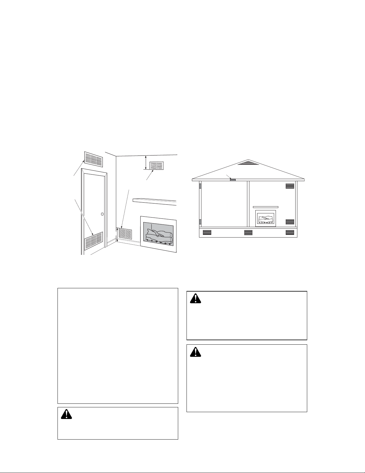
VENTILA TION AIR
Ventilation Air From Inside Building
This fresh air would come from an adjoining
unconfi ned space. When ventilating to an
adjoining unconfi ned space, you must provide
two permanent openings: one within 12" of the
ceiling and one within 12" of the fl oor on the
wall connecting the two spaces (see options
1 and 2, Figure 2). You can also remove door
into adjoining room (see option 3, Figure 2).
Follow the National Fuel Gas Code, ANSI
Z223.1/NFPA 54, Air for Combustion and
Ventilation for required size of ventilation
grills or ducts.
12"
Ventilation
Grills Into
Adjoining
Room,
Option 1
Or
Remove
Door into
Adjoining
Room,
Option
3
Ventilation Grills
Into Adjoining Room,
Option 2
12"
Ventilation Air From Outdoors
Provide extra fresh air by using ventilation
grills or ducts. You must provide two permanent openings: one within 12" of the ceiling
and one within 12" of the fl oor. Connect these
items directly to the outdoors or spaces open
to the outdoors. These spaces include attics
and crawl spaces. Follow the National Fuel
Gas Code, ANSI Z223.1/NFPA 54, Air for
Combustion and Ventilation for required size
of ventilation grills or ducts.
IMPORTANT: Do not provide openings
for inlet or outlet air into attic if attic has a
thermostat-controlled power vent. Heated air
entering the attic will activate the power vent.
Ventilated
Attic
Ventilated
Crawl Space
To Attic
To
Crawl
Space
Outlet
ir
Inlet
Air
Outlet
Air
Inlet Air
Figure 3 - Ventilation Air from Outdoors
Figure 2 - Ventilation Air from Inside Building
INSTALLATION
NOTICE: This heater is intended
for use as supplemental heat.
Use this heater along with your
primary heating system. Do not
install this heater as your primary heat source. If you have a
central heating system, you may
run system’s circulating blower
while using heater. This will help
circulate the heat throughout the
house. In the event of a power
outage, you can use this heater
as your primary heat source.
WARNING: A qualifi ed ser-
vice person must install heater .
Follow all local codes.
WARNING: Any outside air
ducts and/or ash dumps in the
fi replace shall be permanently
closed at time of appliance installation.
WARNING: Seal any fresh
air vents or ash clean-out doors
located on fl oor or wall of fi re-
place. If not, drafting may cause
pilot outage or sooting. Use a
heat-resistant sealant. Do not
seal chimney fl ue damper.
SuperiorFireplaces.us.com
900462-01 NC8
Page 9
INSTALLATION
Continued
W ARNING: Before installing
CHECK GAS TYPE
Use the correct type of gas (natural or propane/
LP). If your gas supply is not the correct gas
type, do not install heater. Call dealer where
you bought heater for proper type heater.
in a solid fuel burning fi replace,
the chimney fl ue and fi rebox
must be cleaned of soot, creosote, ashes and loose paint by
a qualified chimney cleaner.
Creosote will ignite if highly
heated. A dirty chimney fl ue may
WARNING: This appliance is
equipped for either natural gas
or propane/LP gas but not both.
Gas type is indicated on the rating plate. Field conversion is not
permitted.
create and distribute soot within
the house. Inspect chimney and
fi rebox fl ue for damage. If dam-
INST ALLATION AND CLEARANCES
FOR VENT-FREE OPERATION
aged, repair fl ue and fi rebox
before operating heater.
WARNING: Maintain the
minimum clearances. If you can,
W ARNING: Never install the
heater
• in a bedroom or bathroom
• in a recreational vehicle
•
where curtains, furniture, clothing or other fl ammable objects
provide greater clearances from
fl oor, ceiling and adjoining wall.
MINIMUM FIREPLACE CLEARANCE TO
COMBUSTIBLE MATERIALS
Side Wall 16", Ceiling 42"
Floor 5", Front: 36"
are less than 36" from front, 42"
from top of heater; for side clearances see Figure 4, page 10
• in high traffi c areas
• in windy or drafty areas
CAUTION: This heater creates
warm air currents. These currents
move heat to wall surfaces next
to heater. Installing heater next
to vinyl or cloth wall coverings or
operating heater where impurities
(such as, but not limited to, tobacco smoke, aromatic candles,
cleaning fl uids, oil or kerosene
lamps, etc.) in the air exist, may
discolor walls or cause odors.
IMPORTANT: Vent-free heaters add moisture
to the air. Although this is benefi cial, installing
heater in rooms without enough ventilation
air may cause mildew to form from too much
moisture. See Air for Combustion and Ventila-
tion, page 6.
900462-01 NC 9
SuperiorFireplaces.us.com
LOG SIZING REQUIREMENTS
Log
Size
LMF24-
GTA/B
LMF30-
GTA/B
LMF36-
GTA/B
* Also approved for use in VEGA42 and V ALIANT42
SERIES fi replaces.
Carefully follow the instructions below. This
will ensure safe installation into a masonry,
UL127-listed manufactured fi replace or listed
vent-free fi rebox.
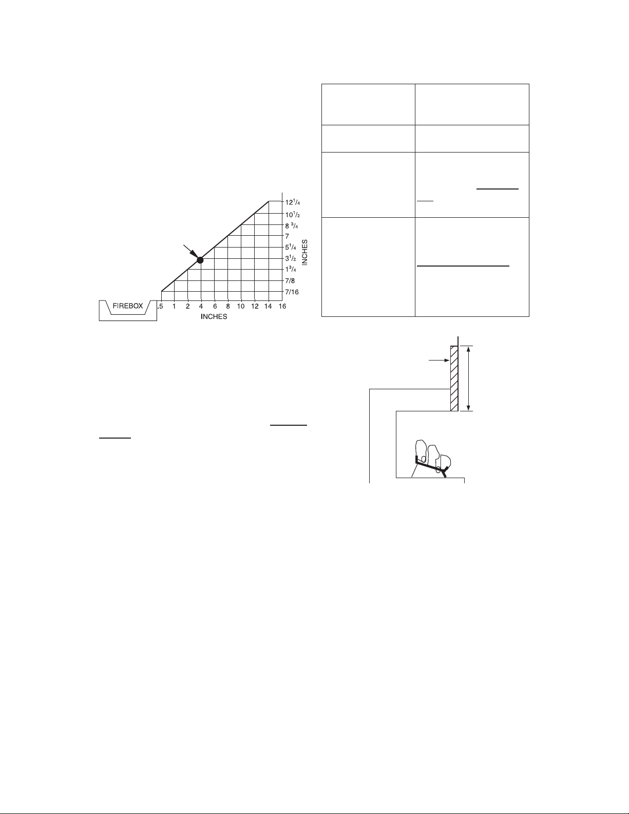
Minimum Clearances For Side Combustible
Material, Side Wall and Ceiling
A. Clearances from the side of the fi replace
cabinet to any combustible material and
wall should follow diagram in Figure 4,
page 10.
Example: The face of a mantel, bookshelf,
etc. is made of combustible material
and protrudes 3
combustible material must be 4" from the
side of the fi replace cabinet (see Figure
4, page 10).
Minimum Firebox Size
Height Depth
29" 15.5" 32.5" 22.75"
29" 15.5" 39" 26.75"
29'' 20'' 47'' 33''
1
Front
Width
/2" from the wall. This
Width
Rear*
Page 10
INSTALLATION
Continued
Note: When installing your gas logs into
a manufactured fi rebox, follow fi rebox
manufacturer’s instructions for minimum
clearances to combustible materials.
B. Clearances from the top of the fi replace
opening to the ceiling should not be less
than 42".
Example
*
*Minimum 16" from Side Wall
Figure 4 - Minimum Clearance for
Combustible to Wall
Minimum Noncombustible Material
Clearances
If Not Using Mantel
Note: If using a mantel proceed to If Using
Mantel. If not using a mantel, follow these
instructions.
You must have noncombustible material(s)
above the fi replace opening. Noncombustible
materials (such as slate, marble, tile, etc.) must
be at least 1/2" thick. With sheet metal, you
must have noncombustible material behind
it. Noncombustible material must extend at
least 8" up (for all models). If noncombustible
material is less than 12", you must install the
fi replace hood accessory (24" and 30" Models
Only). See Figure 5 for minimum clearances.
Noncombustible
Material Distance
Requirements for
Safe Installation
(A)
1
2" or more Noncombustible mate-
rial OK.
Between 8" and 12"
Install fi replace hood
accessory (GA6050 or
GA6053 see Accesso-
ries, page 39).
Less than 8"
Noncombustible material must be extended
to at least 8". See
Between 8" and 12",
above. If you cannot
extend material, you
must operate heater
with fl ue damper open.
Heat Resistant
Material
(A)
Figure 5 - Heat Resistant Material (Slate,
Marble, Tile, etc.) Above Fireplace
If Using Mantel
You must have noncombustible material(s)
above the fi replace opening. Noncombustible
materials (such as slate, marble, tile, etc.)
must be at least 1/2" thick. With sheet metal,
you must have noncombustible material behind it. Noncombustible material must extend
at least 8" up (for all models). If noncombustible material is less than 12", you must
install the fi replace hood accessory. Even if
noncombustible material is more than 12",
you may need the hood accessory to defl ect
heat away from your mantel shelf. See Figure
5 and Figures 6 and 7, page 11, for minimum
clearances.
SuperiorFireplaces.us.com
900462-01 NC10
Page 11

INSTALLATION
Continued
MANTEL CLEARANCES
In addition to meeting noncombustible material clearances, you must also meet required
clearances between fi replace opening and
mantel shelf. If you do not meet the clearances
listed below, you will need a hood.
Determining Minimum Mantel Clearance
If you meet minimum clearance between
mantel shelf and top of fi replace opening, a
hood is not required (see Figure 6).
Mantel Shelf
/2
"
(A)
12"
18" 20" 22" 24"
Distances to
Underside of
Mantel
Underside of
Mantel Shelf
All minimum
distances are
in inches
Top of Fireplace
Opening
Minimum NonCombustible
Material
10"
8"
6"
1
2
Minimum NonCombustible
Material Height
NOTICE: Surface temperatures
of adjacent walls and mantels become hot during operation. Walls
and mantels above the fi rebox
may become hot to the touch.
If installed properly, these temperatures meet the requirement
of the national product standard.
Follow all minimum clearances
shown in this manual.
NOTICE: If your installation does
not meet the minimum clearances shown, you must do one
of the following:
• operate the logs only with the
fl ue damper open
• raise the mantel to an acceptable height
• remove the mantel
Figure 6 - Minimum Mantel Clearances
Without Using Hood
Determining Minimum Mantel Clearance
When Using a Hood
If minimum clearances in Figure 6, are not
met, you must have a hood. When using a
hood there are still certain minimum mantel
clearances required. Follow minimum clearances shown in Figure 7, when using hood.
"
8"
Min.
Mantel Shelf
12" 15" 18" 20"
Distances to
Underside of
Mantel
Underside
of Mantel
Shelf
Top of
Fireplace
Opening
Minimum
Noncombustible
Material
12"
10"
8"
6"
1
/2
2
Hood (GA6050
or GA6053)
FLOOR CLEARANCES
A. If installing appliance on the fl oor level,
you must maintain the minimum distance
of 14" to combustibles (see Figure 8).
B. If combustible materials are less than
14" to the fi replace, you must install ap-
pliance at least 5" above the top surface
of combustible fl ooring including tile and
carpet (see Figure 9).
Combustible
14"
Min.
Noncombustible Material
Figure 8 - Minimum Fireplace Clearances
If Installed at Floor Level
Material
Hearth
Figure 7 - Minimum Mantel Clearances
When Using Hood
5"
Min.
Combustible
Material
Figure 9 - Minimum Fireplace Clearances
Above Combustible Flooring
900462-01 NC 11
SuperiorFireplaces.us.com
Page 12
INSTALLATION
Continued
INSTALLING HEATER BASE
ASSEMBLY
W ARNING: Y ou must secure
this heater to fi replace fl oor. If
not, heater will move when you
adjust controls. Moving heater
may cause a gas leak.
WARNING: If installing in a
sunken fi replace, special care
is needed. You must raise the
fi replace fl oor to allow access to
heater control panel. This will insure adequate air fl ow and guard
against sooting and controls
being damaged. Raise fi replace
fl oor with noncombustible material. Make sure material is secure.
3. Mark screw locations through holes in
front panel of base (see Figure 11). If
installing in a brick-bottom fi replace, mark
screw locations in mortar joint of bricks.
4. Remove heater base from fi replace.
5. Drill holes at marked locations using 3/16"
drill bit.
6. Attach base, through holes in back side panels of base, to fi replace fl oor using masonry
screws provided in hardware package (see
Figure 11).
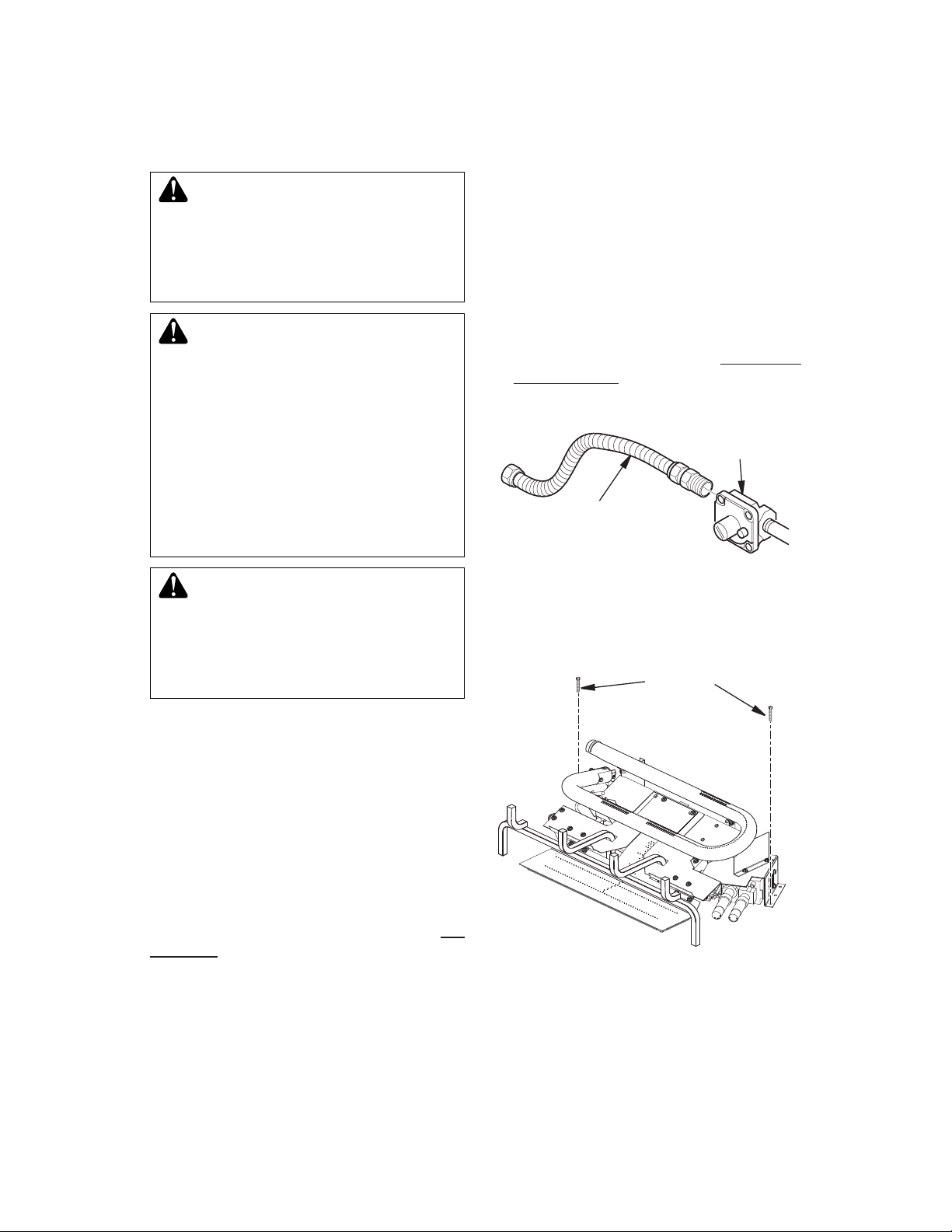
7. Connect to gas supply. See Connecting
To Gas Supply, page 13.
Heater Gas
Regulator
Flexible Gas Hose (Provided
with Models, Install if
allowed by local codes)
CAUTION: Do not pick up
heater base assembly by burners. This could damage heater.
Only handle base assembly by
grates.
IMPORTANT: Make sure the heater burners
are level.
Installation Items Needed
• hardware package (provided with heater)
• approved fl exible gas hose and fi ttings
provided (if allowed by local codes)
• sealant (resistant to propane/LP gas, not
provided)
• electric drill with 3/16” masonry drill bit
Note: Install optional MRC Series receiver
and hand-held remote control kit (see Accessories, page 39) before installing gas log
heater. See installation instructions included
with the kit.
1. Apply pipe joint sealant lightly to male
threads of the 3/8 NPT side of gas fi tting
elbow (provided) and connect to inlet
side of gas control. Remove gas fi tting
from fl exible gas hose (provided) before
connecting to elbow (see Figure 10).
2. Position heater base assembly in fi re-
place.
SuperiorFireplaces.us.com
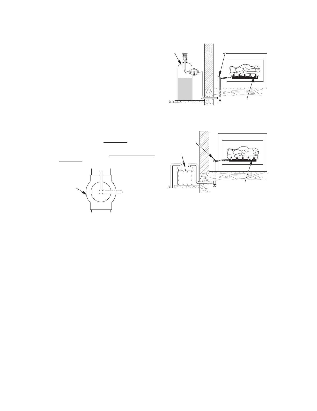
Figure 10 - Attaching Flexible Gas Hose
to Heater Gas Regulator
Masonry Screw
Figure 11 - Attaching Base to Fireplace
Floor
900462-01 NC12
Page 13
INSTALLATION
Continued
CONNECTING TO GAS SUPPLY
WARNING: This appliance
with the vent pointing down as shown in Figure
12, page 14. Pointing the vent down protects
it from freezing rain or sleet.
requires a 3/8" NPT (National
Pipe Thread) inlet connection to
the pressure regulator.
CAUTION: Use only new,
black iron or steel pipe. Internally-tinned copper tubing
WARNING: A qualifi ed service
person must connect heater to
gas supply. Follow all local codes.
may be used in certain areas.
Check your local codes. Use
pipe of 1/2" diameter or greater
to allow proper gas volume to
CAUTION: Never connect
propane/LP fi replace directly
to the propane/LP supply. This
heater requires an external regulator (not supplied). Install the
external regulator between the
heater and propane/LP supply.
WARNING: Never connect
natural gas fi replace to private
(non-utility) gas wells. This
gas is commonly known as
wellhead gas.
Installation Items Needed
Before installing heater, make sure you have
the items listed below.
• external regulator (supplied by installer)
• piping (check local codes)
• sealant (resistant to propane/LP gas)
• equipment shutoff valve *
• test gauge connection *
• sediment trap
• tee joint
• pipe wrench
• approved fl exible gas line with gas connec-
tor (if allowed by local codes) (not provided)
* An equipment shutoff valve with 1/8" NPT
tap is an acceptable alternative to test gauge
connection. Purchase the optional equipment
shutoff valve from your dealer.
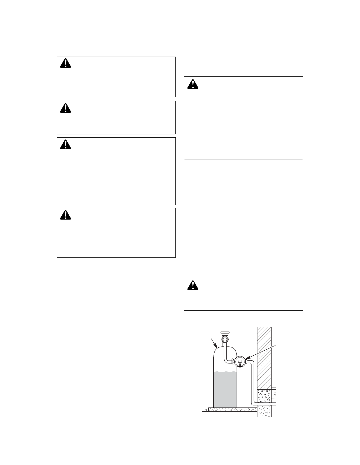
For propane/LP units, the installer must
supply an external regulator. The external
regulator will reduce incoming gas pressure.
You must reduce incoming gas pressure to
between 11" and 14" of water. If you do not reduce incoming gas pressure, heater regulator
damage could occur. Install external regulator
900462-01 NC 13
SuperiorFireplaces.us.com
heater. If pipe is too small, undue
loss of volume will occur.
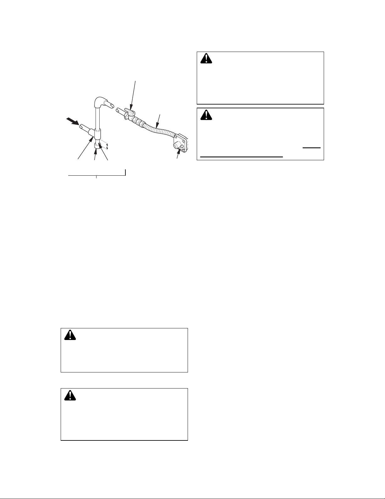
Installation must include an equipment shutoff
valve, union and plugged 1/8" NPT tap. Locate
NPT tap within reach for test gauge hook up.
NPT tap must be upstream from heater (see
Figure 13, page 14).
IMPORTANT: Install equipment shutoff valve
in an accessible location. The equipment
shutoff valve is for turning on or shutting off
the gas to the appliance.
Check your building codes for any special
requirements for locating equipment shutoff
valve to fi replaces.
Apply pipe joint sealant lightly to male NPT
threads. This will prevent excess sealant from
going into pipe. Excess sealant in pipe could
result in clogged heater valves.
WARNING: Use pipe joint
sealant that is resistant to liquid
petroleum (LP) gas.
Propane/LP
Supply Tank
Figure 12 - External Regulator With Vent
Pointing Down
External
Regulator
with Vent
Pointing
Down
Page 14
INSTALLATION
Continued
PROPANE/LP From
External Regulator
(11" W.C.** to 14" W.C.
Pressure)
NATURAL From Gas
Meter (5" W.C.**
to 10.5" W.C.
Pressure)
3" Minimum
Tee Cap Pipe
Joint Nipple
Sediment Trap
Figure 13 - Gas Connection
* Purchase the optional equipment shutoff
valve from your dealer.
**Minimum inlet pressure for purpose of input
adjustment.
We recommend that you install a sediment
trap in supply line as shown in Figure 13.
Locate sediment trap where it is within reach
for cleaning. Install in piping system between
fuel supply and heater. Locate sediment trap
where trapped matter is not likely to freeze.
A sediment trap traps moisture and contaminants. This keeps them from going into heater
controls. If sediment trap is not installed or is
installed wrong, heater may not run properly.
CAUTION: A void damage to
gas control. Hold gas control
with wrench when connecting
it to gas piping and/or fi ttings.
CHECKING GAS CONNECTIONS
WARNING: Test all gas piping
and connections, internal and
external to unit, for leaks after
installing or servicing. Correct
all leaks at once.
Equipment Shutoff
Valve With 1/8"
NPT Tap*
Approved
Flexible Gas
Hose (if allowed
by local codes)
Gas
Regulator
WARNING: Never use an open
fl ame to check for a leak. Apply a
noncorrosive leak detection fl uid
to all joints. Bubbles forming show
a leak. Correct all leaks at once.
CAUTION: Make sure external regulator has been installed
between propane/LP supply and
heater. See guidelines under Con-
necting to Gas Supply, page 13.
PRESSURE TESTING GAS SUPPLY
PIPING SYSTEM
Test Pressures In Excess Of 1/2 PSIG
(3.5 kPa)
1. Disconnect appliance with its appliance
main gas valve (control valve) and equipment shutoff valve from gas supply piping
system. Pressures in excess of 1/2 psig
(3.5 kPa) will damage heater regulator.
2. Cap off open end of gas pipe where equipment shutoff valve was connected.
3. Pressurize supply piping system by either
opening propane/LP supply tank valve
for propane/LP gas or opening main gas
valve located on or near gas meter for
natural gas or using compressed air.
4. Check all joints of gas supply piping system.
Apply noncorrosive leak detection fl uid to
all joints. Bubbles forming show a leak.
5. Correct all leaks at once.
6. Reconnect heater and equipment shutoff
valve to gas supply. Check reconnected
fi ttings for leaks.
Test Pressures Equal To or Less Than 1/2
PSIG (3.5 kPa)
1. Close equipment shutoff valve (see Figure 15).
2. Pressurize supply piping system by either
opening propane/LP supply tank valve
for propane/LP gas or opening main gas
valve located on or near gas meter for
natural gas or using compressed air.
3. Check all joints from gas meter to equipment shutoff valve for natural gas or propane/LP supply to equipment shutoff valve
for propane/LP (see Figure 15 or Figure
16). Apply noncorrosive leak detection fl uid
to all joints. Bubbles forming show a leak.
4. Correct all leaks at once.
SuperiorFireplaces.us.com
900462-01 NC14
Page 15
INSTALLATION
Continued
PRESSURE TESTING HEATER GAS
CONNECTIONS
Open equipment shutoff valve (see Figure 14).
1.
2. Open main gas valve located on or near
gas meter for natural gas or open propane/LP supply tank valve.
3. Make sure control knob of heater is in the
OFF position.
4. Check all joints from gas meter to equipment shutoff valve for natural gas or propane/LP supply to equipment shutoff valve
for propane/LP (see Figure 15, or Figure
16). Apply noncorrosive leak detection fl uid
to all joints. Bubbles forming show a leak.
5. Correct all leaks at once.
6. Light heater (see Operation, page 22).
Check all other internal joints for leaks.
Turn off heater (see To Turn Off Gas to
7.
Appliance, page 22 for Remote models.
Equipment
Shutoff
Valve
Open
Closed
Propane/LP
Supply Tank
Figure 15 - Checking Gas Joints
(Propane/LP Only)
Equipment
Shutoff Valve
Gas Meter
Figure 16 - Checking Gas Joints (Natural
Equipment Shutoff Valve
Control Valve
Location
Control Valve
Location
Gas Only)
Figure 14 - Equipment Shutoff Valve
900462-01 NC 15
SuperiorFireplaces.us.com
Page 16

INSTALLATION
Continued
POWER SUPPLY AND BATTERY
INSTALLATION
It is helpful to have a fl ashlight so you can
see the connections as described below. Locate the battery power supply. It is the black
box with the red and black wires. Locate the
control module (see Figure 17). Connect the
battery power supply to the control module
by plugging the battery power supply to the
mating receptacle on the control module. The
receptacle is located on the side of the black
control module next to the word “SUPPLY”
which is molded in the control module’s black
housing (see Figure 17). Be certain to push
the plug fully into the receptacle. Install batteries in the battery power supply and hand
held remote control.
S1 Button
Touch Pad Wire Harness
Touch Pad Control
Figure 18 - Touch Pad Wire Harness and
Touch Pad Control
Connect Battery Plug Here
Figure 17 - Control Module
TOUCH PAD INSTALLATION
Locate the touch pad wire harness and the
touch pad control (see Figure 18). They are
shipped from the factory in the clear plastic
bag with your owner’s manual. Connect the
black plastic connectors together as shown
in Figure 19. Connect the remaining end
with the white plastic connector to the control
module in the socket marked TOUCH LED
(see Figure 20).
NOTE: The touch pad includes a red LED
display light. If the LED remains on, the black
plug is connected upside down. You must
unplug the touch pad control from the touch
pad wire harness, turn over, and reconnect.
Figure 19 - Touch Pad Control Cable
Figure 20 - Connecting end of Touch Pad
Cable
SuperiorFireplaces.us.com
900462-01 NC16
Page 17

INSTALLATION
Continued
INSTALLING LOGS, EMBERS AND
LAVA ROCK
WARNING: Failure to position
the parts in accordance with these
diagrams or failure to use only
parts specifi cally approved with
this heater may result in property
damage or personal injury.
CAUTION: After installation and periodically thereafter ,
check to ensure that no fl ame
comes in contact with any log.
With heater set to Hi, check to
see if fl ames contact any log. If
so, reposition logs according to
log installation instructions in
this manual. Flames contacting
logs will create soot.
1. Find the right front log (
models: D-061 or
D-019 or LMF36GTA/B models: D-027).
See Figures 22, 22A, 22B, and 22C for
reference. The log has a rectangular
shape on the bottom that fi ts against the
lip on the black metal base, the square
grate, and the round tube burner. Slide
the log in place as shown in Figures.
Burner
Tube
Grate Finger
Figure 22 - Installing Right Front Log
LMF30GTA/B models:
LMF24GTA/B
Right Front Log
(D061, D-019 or D027)
Round Tube
Burner
LOG PLACEMENT
It is very important to install these logs exactly
as instructed. Do not modify logs. Only use
logs supplied with heater or for MF models,
as identifi ed for use with the heater as shown
in Figure 21.
Note: Each log includes an identifying number
cast in the log. Look at each log when placing them on the burner system to be certain
it is correct.
Note: For additional information, go to
www.IHP.US.com and click on the techni-
cal Support tab for access to log placement
videos.
Magnifl ame SERIES BURNER SYSTEM-
LOG COMPATIBILITY CHART
Refractory Concrete
Burner System Model
MFN24INE
MFN24IPE
Logs For Use With This
Burner System
LMF24GTA/B
LMF30GTA/B
Grate Finger
Figure 22A - Installing Right Front Log,
Top View
Burner Tube
Square Grate
MFN30INE
MFN30IPE
Figure 21 - Magnifl ame Log Compatibility
Chart
900462-01 NC 17
LMF36GTA/B
Figure 22B - Installing Right Front Log,
Top View
SuperiorFireplaces.us.com
Page 18

INSTALLATION
Continued
Figure 22C - Installing Right Front Log,
Side View
2. Find the back left log (LMF24GTA/B
models: D-060 or LMF30GTA/B models:
D-018 or LMF36GTA/B models: D-026).
See Figures 23, 23A, and 23B. Figure 23A
shows how the log must fi t against the end
of the burner. Figure 23B shows how the
notch in log fi ts against the vertical portion
of the burner tube. Place this log on the
base assembly by inserting it from the left
side as shown in Figure 23. You will need
to twist the log slightly to get it to fi t against
the burners properly. It will rest even with
the back edge of the pan.
3. Find the front left log (
Back Left Log (D-060,
D-018 or D026)
Flat Part of Log
LMF24GTA/B
Vertical Portion of Burner Tube
Figure 23B - Installing Back Left Log
(D-018) Rear View
models: D-059 or LMF30GTA/B models:
D-017 or LMF36GTA/B models: D-025).
See Figures 24, 24A, and 24B. The log
has a rectangular stand off on the bottom
that fi ts against the lip on the black metal
base as shown in fi gure 24A. The bottom
of this log has a slot that fi ts over the sec-
ond bar on the grate as shown in Figure
24B, page 19. Place the log on the base
assembly as shown in fi gures.
4. Find the charred log (D-020). See Figures
Front Left Log (D-059,
D-017 or D025)
Log Notch
Burner Tube
Figure 23 - Installing Back Left Log
Log
Notch
Burner
Tube
Figure 23A - Installing Back Left Log
SuperiorFireplaces.us.com
Grate Fingers
Figure 24 - Installing Front Left Log
Figure 24A - Installing Front Left Log
Side View
900462-01 NC18
Page 19

INSTALLATION
Continued
Square Grate
Log Notch
Grate Finger
Log Slot
Figure 24B - Installing Front Left Log
25, 25A, and 25B. The log has a slot in the
bottom that fi ts over the square grate and
rests against the burner tube as shown in
Figure 25. Place this log on the base as
shown in fi gures.
5. Find the middle split log (
Charred
Log
Log Notch
Right Front Log
LMF24GTA/B
Figure 25B - Installing Charred Log Top
Side View
models: D-063 or LMF30GTA/B models:
D-021 or LMF36GTA/B models: D-028).
See Figures 26 and 26A. The split side
of the log faces forward. The log has a
notch that fi ts around the burner tube on
the right side. The left side of the burner
tube fi ts into the notch on the back side of
this log. The log is placed properly when
it sits parallel to the tube burner and the
square peg is pointing up. See fi gures
for reference.
6. Find the right split crossover log (D-022)
Square Peg
Figure 25 - Installing Charred Log
Middle Split Log (D-063,
D-021 or D028)
Figure 26 - Installing Middle Split Log
(D-021)
Burner Tube
Log Notch
Figure 25A - Installing Charred Log Top
View
Figure 26A - Installing Middle Split Log
Rear Top Side View
900462-01 NC 19
SuperiorFireplaces.us.com
Page 20

INSTALLATION
Continued
The bottom of the log has a rectangular
stand off that fits in the slots on the
right side of the front right log and the
middle split log. Place this log as shown in
Figure 27.
7. Find the front top log (D-024). See Figure
Square Peg
Right Front Log
Right Split Crossover Log (D-022)
Figure 27 - Installing Right Split
Crossover Log
28. The left end of this log has a square hole
that fi ts over a square peg that is on the top
of the middle split log. The right end of this
log rests behind the knot on the top of the
front right log.
8. Find the back top log (
Front Top Log (D-024)
LMF24GTA/B mod-
Right Split Crossover Log (D-022)
Rectangular
Peg
Back Top Log (D-062,
D-023 or D029)
Right Split Crossover Log (D-022)
Figure 29 - Installing Back Top Log and
Final Assembly
Figure 29A - Installing Back Top Log,
Top View
Middle Split Log
Figure 28 - Installing Front Top Log
els: D-062 or
LMF30GTA/B models:
D-023 or LMF36GTA/B models: D-029).
See Figures 29, and 29A. The left end of this
log has a round hole that fi ts over the round
peg that is on the top of the back left log. The
right end of this log has a rectangular hole
that fi ts over the rectangular peg on the top
of the right crossover log.
Two ember materials are supplied with this
SuperiorFireplaces.us.com
900462-01 NC20
Page 21

INSTALLATION
Continued
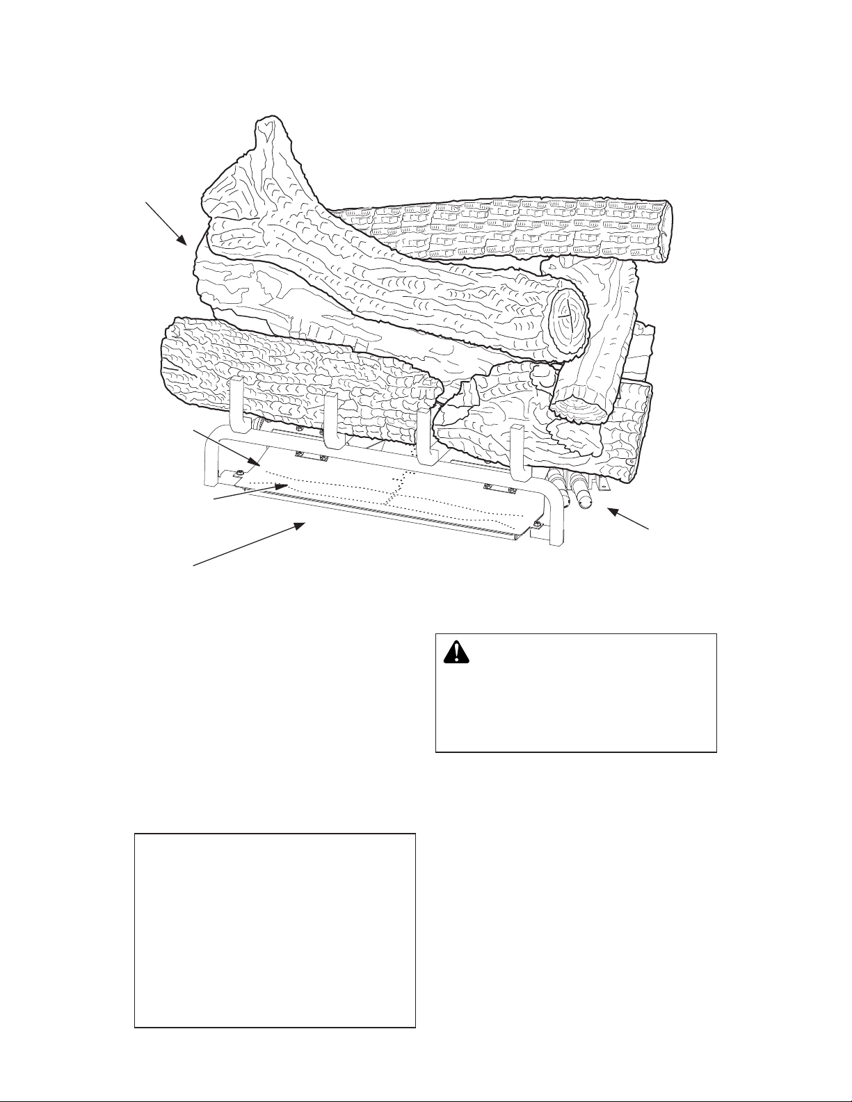
EMBER PLACEMENT
log set. Platinum Bright Embers give a bright
glow appearing as hot coals. Should embers
need replacing, see Accessories, page 39.
• Platinum Bright Ember placement.
Add embers to front, fl at burner. Gently
remove embers from bag. Separate
pieces of ember material and place on
surface of fl at burner just behind hori-
zontal ports as shown in Figure 30.
• Rock Wool placement. Place rock wool
WARNING: Do not use any other
ember material not supplied with
this unit.
WARNING: Do not operate unit
without ember material correctly in
place as shown in Figures 30 & 31. Do
NOT place ember material anywhere
else on the unit. Use only ember material supplied with unit. Excessive or
incorrectly placed ember material may
produce carbon monoxide or soot. If
replacement embers are needed,
the replacement embers must be
purchased from IHP. See page 41
for part numbers.
WARNING: All previously applied loose material must be removed prior to reapplication.
LAVA ROCK PLACEMENT
material on front fl at burner in areas away
from ports as shown in Figure 31.
• Add lava rock; Lava rock may cover 1/2
inch of the front burner(fl at metal ember
pan burner) but shall not be allowed to
come in contact with either the burner
ports or fl ame around base of heater if de-
sired. DO NOT place rock or additional
logs on front burner or on logs except
as directed above. Placing any material
on unit other than ember material on front
burner may result in production of carbon
monoxide or soot. A switch log is included
with each log set. This log is designed to
house a switch on remote ready models.
On variable remote models, this switch is
not needed. The log can be placed on the
fl oor of the fi replace to enhance the look
of the log set. Use lava rock to hide wires
from switch/log to control valve. Place
switch/log so the switch is easy to access.
Ember Material
Figure 30 - Platinum Bright Embers
Rock Wool
Figure 31 - Placement of Rock Wool (shown with Platinum Bright Embers)
900462-01 NC 21
SuperiorFireplaces.us.com
Flat Front Burner
Page 22

OPERATION
NOTICE: During initial operation
of new heater , burning logs will
give off a paper-burning smell.
Orange fl ame will also be pres-
ent. Open damper or window to
vent smell. This will only last a
few hours.
WARNING:
• If fi replace has glass doors,
never operate this heater with
glass doors closed. If you operate heater with doors closed,
heat buildup inside fi replace
will cause glass to burst. Make
sure there are no obstructions
across openings of fi replace.
• You must operate this heater
with a fi replace screen in place.
Make sure fi replace screen is
closed before running heater .
WARNING: Damper handle
will be hot if heater has been
running.
CAUTION: Do not try to adjust heating levels by using the
equipment shutoff valve.
FOR YOUR SAFETY
READ BEFORE LIGHTING
W ARNING: If you do not follow these instructions exactly,
a fi re or explosion may result
causing property damage, personal injury or loss of life.
A. This appliance is equipped with an igni-
tion device which automatically lights
the pilot. Do not light pilot by hand..
B. BEFORE LIGHTING smell all around
the appliance area for gas. Be sure to
smell next to the fl oor because some
gas is heavier than air and will settle
on the fl oor.
WHAT TO DO IF YOU SMELL GAS
• Do not try to light any appliance.
• Do not touch any electric switch; do
not use any phone in your building.
• Immediately call your gas supplier
from a neighbor’s phone. Follow the
gas supplier’s instructions.
• If you cannot reach your gas supplier,
call the fi re department.
C. Do not use this appliance if any part
has been under water. Immediately call
a qualifi ed service technician to inspect
the appliance and to replace any part of
the control system and any gas control
which has been under water.
LIGHTING
INSTRUCTIONS
1. STOP! Read the safety information.
2. Make sure equipment shutoff valve is
fully open.
3. Press any button on the remote to power
the remote on. Press the MODE zone or
the MODE/SET Button to start the unit.
You will hear a beep from the control
module and the pilot will start to light the
unit.
Note: Y ou may be running this heater for the
fi rst time after hooking up to gas supply.
If so, you may have to restart the unit
several of times to allow the air to bleed
from the system.
TO TURN OFF GAS
TO APPLIANCE
1. Once you have activated the screen press
the MODE Zone or MODE/SET Button
until you see OFF.
2. Close equipment shutoff valve.
SuperiorFireplaces.us.com
900462-01 NC22
Page 23

OPERATION
Continued
REMOTE CONTROL OPERATION
BASIC CONSTRUCTION
• Touch-Screen LCD and three push buttons will allow input from users.
• LCD screen will provide system status & input feedback to user.
• Backlight will illuminate LCD screen for 5 seconds after any user input – the 1st touch
of the LCD screen will only illuminate the backlight (will not respond to associated zone
function). To activate any command, the backlight for the screen must be on and the
command must be touched before the backlight goes off.
• Powered via four AAA sized batteries (6V nominal) with LOW BATTERY INDICATOR
(5.0V).
Touch-Screen LCD and Button Layout (Not to scale)
SET TEMP Zone
FLAME Zone
CHANNEL UNLOCK Zone
DOWN Button
Figure 32 - Touch-Screen LCD and Button Layout
ON THERMO OFF
Cont.
Pilot
P1
P1
A
°
SET
S M T W T F S
PROGRAM
MODE/SET
u
:
ROOM
°
P2
AM
PM
P2
MODE Zone
ROOM TEMP Zone
TIME/PROG Zone
CHANNEL PROG Zone
MODE/SET Button
UP Button
900462-01 NC 23
SuperiorFireplaces.us.com
Page 24

OPERATION
Continued
FUNCTIONAL DESCRIPTION
Note: All function adjustments will be automatically accepted 15-seconds after pressing
a given touch zone or button. The user may
press the MODE/SET button to immediately
accept the adjustment manually.
CHANNEL SELECTION
This control may be operated in 3 different
sub-channels for applications where 2.4GHz
interference causes delayed operation of the
remote control. The factory default is Channel
3. To change the channel on the transmitter:
• Touch the CHANNEL PROGRAM and
CHANNEL UNLOCK zones simultaneously and hold for 5-seconds.
• The LCD screen will go blank except
“Ch” will be displayed in the SET TEMP
Zone and either “01”, “02”, or “03” will
be displayed in the ROOM TEMP Zone.
• Press the UP or DOWN buttons to
change the channel number (01-03).
• Press the MODE/SET Button to return
to the normal operating display.
Receiver Operation Notes:
• The receiver manufacturer may refer to
channels 01, 02, or 03.
• Receiver must be paired with transmitter
in the receiver’s factory default channel.
• Once paired, the channel selection may
be changed in the transmitter per the
instructions above.
• Once the channel selection is changed in
the transmitter, the power supply to the
receiver must be removed for at least
30-seconds, then re-applied.
• The receiver will recognize the new
channel selection after about 30-seconds to 1-minute and normal operation
will resume.
MODES OF OPERATION
OPERATION MODES:
• MANUAL OFF
• MANUAL ON
• THERMOSTAT (with optional PROGRAM Mode)
The modes may be cycled in the order above
by touching the MODE Zone or pressing the
MODE/SET Button.
SuperiorFireplaces.us.com
MANUAL OFF MODE:
• Transmits fl ame OFF command.
• Pilot Method: Intermittent Pilot Ignition
(IPI)/Spark-to-Pilot only (continuous/
standing pilot not allowed)
• Pilot fl ame will be turned OFF
• LCD Displays:
• MODE Zone: OFF is displayed
• ROOM TEMP Zone: Measured temperature is displayed
• SET TEMP Zone: Blank
• TIME/PROG Zone: Current day indica-
tor and current time is displayed
• FLAME Zone: Blank
MANUAL ON MODE:
• Transmits fl ame ON command.
• Pilot Method: Intermittent Pilot Ignition
(IPI)/Spark-to-Pilot only (continuous/
standing pilot not allowed)
• Pilot fl ame will be ignited before turn
Main Flame ON.
• LCD Displays:
• MODE Zone: ON is displayed
• ROOM TEMP Zone: Measured temperature is displayed
• SET TEMP Zone: Blank
• TIME/PROG Zone: Current day indicator
and current time is displayed
• FLAME Zone: A Flame Icon and fl ame
setting level number is displayed
THERMOSTAT MODE:
• Will cycle fl ame on and off based on
room and set temperatures. Will transmit
ON command if SET TEMP (+SWING)
is higher than ROOM TEMP and will
transmit OFF command if SET TEMP
(-SWING) is lower than ROOM TEMP.
• Built-in thermostat will measure room
temperature.
• All programming should be written for
deg. F and converted to deg. C when
selected.
• Temperatures may be displayed in
degrees F (factory default) or degrees
C. Press the UP and DOWN Buttons
simultaneously to change between
degrees F and C.
• SET TEMP: While in THERMOSTAT
mode, press the UP or DOWN Button
900462-01 NC24
Page 25

OPERATION
Continued
to change the SET TEMP (45-90 deg. F,
7-32 deg. C); the new set temperature
will automatically be accepted after 2
seconds. The factory default SET TEMP
is 68 deg. F.
• SWING Temperature: This model does
not allow for SWING temperature adjustment. This model utilizes thermostatic
fl ame modulation that will modulation
the main fl ame based on the difference
between room temperature and set temperature (see example below).
• Important - factory SWING TEMPERATURE setting is 2 degrees. The thermostatic fl ame modulation feature will not
allow this SWING to be changed.
EXAMPLE:
Set Temperature Room Temp. Flame Level
74F OFF
73F Level 1
Set Temperature (72) 72F Level 2
71F (or less) Level 3
• Pilot Method: Continuous/Standing Pilot
only (Intermittent Pilot Ignition (IPI)/
Spark-to-Pilot not allowed).
• Pilot fl ame will remain ON when Main
Flame Cycles ON and OFF.
• Manual Flame Adjustment while in
THERMOSTAT mode: If Flame-A is
manually adjusted while in thermostat
mode, it will override the automatic
fl ame setting until the fl ame cycles off,
then back ON thermostatically; when
the fl ame cycles ON again, automatic
fl ame adjustment will resume. Automatic
fl ame adjustment will also resume if the
operational mode is cycled out of, then
back into THERMOSTAT mode or if the
SET temperature is changed.
• THERMOSTAT OFF LCD Displays:
• MODE Zone: THERMO and OFF is
displayed
• ROOM TEMP Zone: Measured temperature is displayed
• SET TEMP Zone: SET TEMP is displayed
• TIME/PROG Zone: Current day indicator
and current time is displayed
• FLAME Zone: Blank
• THERMOSTAT ON LCD Displays:
900462-01 NC 25
SuperiorFireplaces.us.com
• MODE Zone: THERMO and ON are
displayed
• ROOM TEMP Zone: Measured temperature is displayed
• SET TEMP Zone: SET TEMP is displayed
• TIME/PROG Zone: Current day indicator
and current time is displayed
• FLAME Zone: A Flame Icon and fl ame
setting level number is displayed
Thermostat Disable Feature
• The Thermostat Mode (described above)
may be disabled for applications where a
thermostat is not allowed or undesirable.
When Thermostat Mode is Disabled:
• The Modes of operation will cycle between MANUAL ON and MANUAL OFF
(omitting THERMO).
• Program Operation (described below) is
also disabled.
• The SET TEMP zone will be blank.
• The room temperature will still be measured & displayed in the ROOM TEMP
Zone.
• The TIME/PROG zone will continue to
display the Clock and Day of week, but
none of the icons associated with Program Mode will be displayed.
• To disable or re-enable the Thermostat,
the transmitter must be in MANUAL
OFF Mode, then touch and hold the
SET TEMP Zone and the DOWN Button
simultaneously for 10- seconds. The
LCD screen will go blank except either
THERMO and OFF or THERMO and
ON will fl ash 3-times (0.5-seconds OFF,
0.5-seconds ON) to indicate the change
has been made.
DAY AND TIME DISPLAY
• The current day of week and time of
day will be continuously displayed in the
TIME/PROG Zone (except during Setup
operations).
• The day of week will be displayed as
one of the following: S, M, T, W, T, F, S
• The time of day will be in 12-hour AM,
12-hour PM format. Midnight will be
displayed as 12:00am.
• Day/Time Setup:
1. Touch and hold the MODE Zone for 5
seconds to enter Day/Time Setup.
Page 26

OPERATION
Continued
2. Press the UP or DOWN Buttons to adjust
the day of week (press the MODE/SET
Button or wait for 15 seconds for adjustment to be accepted, then enter hour of
day adjustment).
3. Press the UP or DOWN Buttons to
adjust the hour of the day. The time will
advance in 1-hour increments; AM and
PM will change when the hour advances
to 12:00 midnight and 12:00 noon respectively (press the MODE/SET Button
or wait for 15 seconds for adjustment to
be accepted, then enter minute of hour
adjustment).
4. Press the UP or DOWN Buttons to adjust the minute of the hour. The time will
advance in 1-minute increments (press
the MODE/SET Button or wait for 15
seconds and the transmitter will exit
Day/Time Setup and return to normal
operation).
5. LCD Displays – when in Day/Time
Setup:
• MODE Zone: Blank
• ROOM TEMP Zone: Blank
• SET TEMP Zone: Bank
• TIME/PROG Zone: Day of Week, or
Time of Day will Flash
FLAME Zone: Blank
Program Operation
• Touch the TIME/PROG Zone to activate
or deactivate Program Operation. Touching the MODE Zone or pressing the
MODE/SET Button will also deactivate
Program Operation. When Program Operation is deactivated, the transmitter will
return to MANUAL OFF Mode.
• Program Operation will cycle fi replace
ignition ON and OFF based on time settings (2 weekend periods and 2 weekday
periods) and thermostat settings. Press
the MODE/SET Button or wait for 15
seconds to advance to each subsequent
program setting.
• Pilot Method (same as Thermostat
Mode): Continuous/Standing Pilot
only (Intermittent Pilot Ignition (IPI)/
Spark-to-Pilot not allowed).
• Pilot fl ame will remain ON when Main
Flame Cycles ON and OFF.
• To enter Program Setup, touch and hold
the TIME/PROG Zone for 5 seconds.
• Program OFF LCD Displays:
• MODE Zone: OFF
• ROOM TEMP Zone: Measured temperature is displayed
• SET TEMP Zone: Blank
• TIME/PROG Zone: Current day indicator, current time, and Program status
(P1- OFF or P2-OFF) is displayed
• FLAME Zone: Blank
• Program ON LCD Displays:
• MODE Zone: THERMO and either ON
or OFF is displayed
• ROOM TEMP Zone: Measured temperature is displayed
• SET TEMP Zone: SET TEMP is displayed
• TIME/PROG Zone: Current day indicator, current time, and Program status
(P1- ON or P2-ON) is displayed
• FLAME Zone:
If Thermostat is ON, A Flame Icon and
fl ame setting level number is displayed.
If Thermostat is OFF, display is blank.
Program Disable Feature
• The Program Mode (described above)
may be disabled for applications where
a program operation is not allowed or
undesirable. When Program Mode is
Disabled:
• The user will not be able to activate
Program Mode
• The user will not be able to enter
Program Setup or edit Program Mode
settings.
• The TIME/PROG zone will continue to
display the Clock and Day of week, but
none of the icons associated with Program Mode will be displayed.
• To disable or re-enable the Program
Mode, the transmitter must be in MANUAL OFF Mode, then touch and hold the
TIME/PROG Zone and the DOWN Button simultaneously for 10-seconds. The
LCD screen will go blank except either
PROGRAM and OFF (OFF display in
MODE Zone) or PROGRAM and ON (ON
display in MODE Zone) will fl ash 3-times
(0.5-seconds OFF, 0.5-seconds ON) to
indicate the change has been made.
SuperiorFireplaces.us.com
900462-01 NC26
Page 27

OPERATION
Continued
Flame-A (or Main) Adjustment
• Transmits a fl ame height setting com-
mand to the control module to adjust the
Flame-A height.
• Available settings are 1-3 with a factory
default of 3. Refer to the THERMOSTAT
Mode section for additional details on
flame modulation in THERMOSTAT
mode.
• While in MANUAL ON, THERMOSTAT
ON, or PROGRAM ON modes, touch
the FLAME Zone to enter Flame-A Adjustment, then press the UP or DOWN
buttons to raise and lower the fl ame;
press the MODE/SET Button or wait for
15 seconds to accept the new setting.
• LCD Display: When setting the Flame-A
height, the Flame-A icon, and Flame-A
setting number will fl ash in the FLAME
Zone.
Child-Lock Operation
• Child-Lock operation prevents any user
input to the transmitter. No mode of operation or feature may be adjusted when
Child-Lock is activated. All automatic
functions (thermostat, program, etc.) will
continue normally.
• To activate or deactivate the Child-Lock
feature, press and hold the MODE/SET
and DOWN Buttons simultaneously for
5 seconds.
• LCD Displays:
• When activated, the LOCK icon will appear in the MODE Zone.
• If any touch-zone or button is pressed
when activated, the LCD backlight will
illuminate and the LOCK icon will fl ash
for 5 seconds in the MODE Zone.
Room Temperature Limit
• The Room Temperature Limit Shutdown feature will operate in MANUAL
ON, THERMOSTAT ON mode, and
PROGRAM ON modes. If the room temperature reaches 95 deg. F or greater,
the transmitter will automatically change
to MANUAL OFF mode and send a
MANUAL OFF command to the control
module. If the user turns the control
back ON and the room temperature is
still 95F or greater, the transmitter will
switch to back manual OFF and send
another OFF command the next time
900462-01 NC 27
SuperiorFireplaces.us.com
the transmitter reads & updates the room
temperature (2-minute update interval).
PAIRING
The remote and receiver are paired at the
factory but in case they do not communicate
after proving the batteries are fresh, repairing
may be necessary. Follow the steps below to
repair the remote to the receiver.
It is helpful to have a fl ashlight so you can
see the connections as described below.
Before proceeding, locate the S1 button on
the receiver shown in the fi gure below. You
will need to access this button during the repairing procedure and only have 20 seconds
to press and release it.
• To enter pairing mode press and hold
the MODE/SET Button for 10-seconds.
• Transmitter will transmit a pairing signal for 20-seconds, then automatically
exit pairing mode and return to normal
operation.
• LCD Displays – When pairing mode is
activated:
1. MODE Zone: Blank
2. ROOM TEMP Zone: The letters “On”
will fl ash.
3. SET TEMP Zone: The letter “P” is
displayed
4. TIME/PROG Zone: Blank
5. FLAME Zone: Blank
Receiver Operation Note: Once transmitter
is in pairing mode, press the yellow or black
pairing button on the receiver.
S1 Button
Connect Battery Plug Here
Figure 17 - Control Module
Page 28

OPERATION
Continued
TOUCH PAD OPERATION
This touch control has only 3 buttons for controlling manually the fl ame of the appliance
(see Figure 33).
The touch pad has:
1. Led display
2. ON/OFF button
3. UP button
4. DOWN button
With this control it is possible to turn on the
fi re, turn off the fi re and control the fl ame level.
LED Display
ON/OFF Button
ON
OFF
UP Button
DOWN Button
Note: The touch pad includes a red LED
display light. If the LED remains on, the black
plug is connected upside down. Unplug, turn
over, and reconnect.
SWITCHING ON
To turn the system on just press the ON/OFF
button. The system will emit a beep and begin
the ignition process, which can take about
20 seconds. Once the start up process is
complete, the pilot fl ame is lit.
REGULATING THE FLAME LEVEL.
1. To increase the fl ame level, press the
up button (
the LED indicate that the system has
accepted the order, and the fl ame will
increase instantly (see Figure 33).
2. To decrease the fl ame level, press the
down button (
the LED indicate that the system has
accepted the order, and the fl ame will
decrease instantly (see Figure 33).
). A beep and a fl ash of
). A beep and a fl ash of
SWITCHING OFF
To switch off the fi re, the ON/OFF button
should be pressed. After the system has emitted a beep, the fi re switches off.
Figure 33 - Touch Pad Control
WARNING: Do not convert
heater to use different fuel type.
Only use heater with fuel type
specifi ed.
SuperiorFireplaces.us.com
900462-01 NC28
Page 29

INSPECTING BURNERS
CLEANING AND
MAINTENANCE
Thermocouple
Figure 34 - Pilot (Natural)
Check pilot fl ame pattern and burner fl ame
patterns often.
Ignitor Electrode
Pilot Burner
PILOT FLAME PATTERN
Figure 35 shows a correct pilot fl ame pattern.
Figure 36 shows an incorrect pilot fl ame pat-
tern. The incorrect pilot fl ame is not touching
the thermocouple. This will cause the thermocouple to cool. When the thermocouple cools,
the heater will shut down.
If pilot fl ame pattern is incorrect, as shown
in Figure 36.
• turn heater off (see To T urn Off Gas to Ap-
pliance, page 22
• see Troubleshooting, page 32
Note: The pilot fl ame on natural gas units will
have a slight curve, but fl ame should be blue
and have no yellow or orange color.
Thermocouple
Figure 35 - Correct Pilot Flame Pattern
(Your pilot may vary from pilots shown)
Thermocouple
Figure 36 - Incorrect Pilot Flame Pattern
(Your pilot may vary from pilots shown)
Pilot Burner
Pilot Burner
WARNING: Turn off heater
and let cool before cleaning.
CAUTION: You must keep
control areas, burners and
circulating air passageways of
heater clean. Inspect these areas
of heater before each use. Have
heater inspected yearly by a qualifi ed service person. Heater may
need more frequent cleaning due
to excessive lint from carpeting,
pet hair , bedding material, etc.
WARNING: Failure to keep
the primary air opening(s) of
the burner(s) clean may result
in sooting and property damage.
BURNER INJECTOR HOLDER AND
PILOT AIR INLET HOLE
The primary air inlet holes allow the proper
amount of air to mix with the gas. This provides
a clean burning fl ame. Keep these holes clear
of dust, dirt, lint and pet hair. Clean these air inlet holes prior to each heating season. Blocked
air holes will create soot. We recommend that
you clean the unit every three months during
operation and have heater inspected yearly by
a qualifi ed service person.
We also recommend that you keep the burner
tube and pilot assembly clean and free of dust
and dirt. To clean these parts we recommend
using compressed air no greater than 30 PSI.
Your local computer store, hardware store or
home center may carry compressed air in a
can. If using compressed air in a can, please
follow the directions on the can. If you don’t
follow directions on the can, you could damage the pilot assembly.
1. Shut off unit, including pilot. Allow unit to
cool for at least thirty minutes.
2. Inspect burner, pilot and primary air inlet
holes on injector holder for dust and dirt
(see Figure 37, page 30).
3. Blow air through the ports/slots and holes
in the burner.
900462-01 NC 29
SuperiorFireplaces.us.com
Page 30

CLEANING AND MAINTENANCE
Continued
4. Check injector holder located at end of
burner tube again. Remove any large
particles of dust, dirt, lint or pet hair with
a soft cloth or vacuum cleaner nozzle.
5. Blow air into the primary air holes on the
injector holder.
6. In case any large clumps of dust have now
been pushed into the burner repeat steps
3 and 4.
Clean pilot assembly also. Additional cleaning may be needed for proper pilot operation
based on use/lack of use. A yellow tip on the
pilot fl ame may indicate dust and dirt in the
pilot assembly. There is a small pilot air inlet
hole about from where the pilot fl ame comes
out of pilot assembly (see Figure 38). With
unit off, lightly blow air through air inlet hole.
You may blow through a drinking straw if
compressed air is not available.
Injector
Holder
LOGS
• If you remove logs for cleaning, refer to
Installing Logs Embers and Lava Rock,
page 17, to properly replace logs.
• Replace log(s) if broken or chipped (dimesized or larger).
MAIN BURNER
Periodically inspect all burner fl ame holes with
heater running. All slotted burner flame holes
should be open with fl ame present. All round burner
fl ame holes should be open with a small blue fl ame
present. Some burner fl ame holes may become
blocked by debris or rust, with no fl ame present. If
so, turn off heater and let cool. Remove blockage,
blocked burner fl ame holes will create soot.
W ARNING: The injector holders (air shutters) are not adjustable. Do not move injector holders
from their original positions.
Burner Tube
Primary Air
Inlet Holes
Figure 37 - Injector Holder On Outlet
Burner Tube
Pilot Air
Inlet Hole
Pilot Assembly
Figure 38 - Pilot Inlet Air Hole (Your pilot
may vary from pilot shown)
SPECIFICATIONS
MNF24INE AND MNF30INE
• Rating (Variable): 28,000/38,000 Btu/Hr
• Type Gas: Natural
• Ignition: Electronic
• Manifold Pressure: 4.5" W.C.
• Inlet Gas Pressure (in. of water):
Max - 10.5" W.C., Min* - 5" W.C.
*For purpose of input adjustment
MNF24IPE AND MNF30IPE
• Rating (Variable): 31,000/39,000 Btu/Hr
• Type Gas: Propane/LP
• Ignition: Electronic
• Manifold Pressure: 8.0" W.C.
• Inlet Gas Pressure (in. of water):
Max - 14" W.C., Min* - 11" W.C.
*For purpose of input adjustment
SuperiorFireplaces.us.com
900462-01 NC30
Page 31

WIRING DIAGRAM
°
P2
P2
AM
ROOM
u
Pilot
Cont.
ON THERMO OFF
REMOTE CONTROL
PM
:
PROGRAM
°
S M T W T F S
SET
A
P1
P1
MODE/SET
CONTROL MODULE
POWER SUPPLY BOX
900462-01 NC 31
SuperiorFireplaces.us.com
Page 32

TROUBLESHOOTING
W ARNING: Turn off heater and let cool before servicing. Only a
qualifi ed service person should service and repair heater.
CAUTION: Never use a wire, needle or similar object to clean
ODS/pilot. This can damage ODS/pilot unit.
Note: All troubleshooting items are listed in order of operation.
OBSERVED PROBLEM
Either the remote or touch pad buttons are pressed to start the burner
ignition sequence and there is no
function or response.
POSSIBLE CAUSE
1. Missing or weak batteries at
power supply box or remote. Control module may beep 10 times or
may not beep at all. LCD display
may show "BATTERY ERROR".
2. Unplugged power supply (battery)
box
3. Touch pad not plugged in to module or plugged in incorrectly
4. Control valve wiring harness not
plugged in or not in proper position
REMEDY
1. Check batteries and replace if
needed. (Batteries in the power
supply box can be tested with a
multimeter at the two connections
at the back of the battery housing
where the red and black wires are
connected. Set the multimeter to
DC voltage, initiate the ignition
sequence, and observe the voltage while the system is lighting
(under load). The system will not
function under 3.8 volts and batteries should be replaced if the
voltage is under 4.0 volts.)
2. Plug power supply box to module
see page 16.
3. Plug touch pad in module see
page 16, fi gure 19. Check to see
it is positioned as shown.
4. Check to see that the control valve
wiring harness' blue connector is
plugged in to the module. Check
to see that it is aligned with the
mating pins. If any pins are visible,
then the connector is not in the
correct position. If this is the case,
disconnect, align, and reconnect
to the module.
5. Remote not communicating with
control module
SuperiorFireplaces.us.com
5. The remote communicates with
the module periodically. It doesn't
communicate with the module
continuously to conserve battery
power.
900462-01 NC32
Page 33

TROUBLESHOOTING
Continued
OBSERVED PROBLEM
Either the remote or touch pad buttons are pressed to start the burner
ignition sequence and there is no
function or response. (Continued
from page 32).
POSSIBLE CAUSE
6. LED is blinking
7. Ignitor cable is not connected
8. Ignitor cable pinched or wet
9. Broken Ignitor cable.
10. Ignitor electrode positioned
wrong.
11. Ignitor electrode broken.
12. Control module sounds 2 cycles
of 3 beeps; LCD display may
show ROM ERROR
13. Control module sounds 2 cycles
of 5 beeps; LCD display may
show SUPPORT ERROR
REMEDY
6. This indicates the battery power is
low. Replace the batteries in the
power supply box.
7. Check the ignitor connection at
both the control module and the
ods pilot. Connect if loose.
8. Free ignitor cable if pinched by
any metal or tubing. Keep ignitor
cable dry.
9. Replace wire harness including
ignitor cable.
10. Replace ods pilot assembly.
11. Replace ods pilot assembly.
12. Replace control module
13. Ground cable from control valve
wiring harness is not grounding properly. Reposition spade
terminal so that it makes contact
with burner chassis metal or
valve body.
14. Bad reception from remote
15. If LED on touch pad is continuously on, the cable is connected
the wrong way.
16. The control module sounds 2
cycles of 5 beeps. The wiring
assembly from the control valve
is disconnected or broken.
14. Change batteries in remote.
Check reception of signal from
a shorter distance. If still not
working, try changing the channel in the configuration menu.
If this does not fi x the problem,
reset the channel (see page 24
Channel Selection) and follow
the instructions in Pairing on page
24. Replace remote and control
module as a fi nal action.
15. Disconnect the touch pad between the long and short cables,
turn the short cable with the touch
pad over and reconnect.
16. Connect the wiring harness at the
control module. Replace the valve
assembly if all other cause/remedies fail to correct his problem.
900462-01 NC 33
SuperiorFireplaces.us.com
Page 34

TROUBLESHOOTING
Continued
OBSERVED PROBLEM
When ignitor button is pressed on the
remote or touch pad, the pilot sparks
but there is no ignition.
POSSIBLE CAUSE
1. Gas supply turned off or equipment shutoff valve closed
2. Air in gas lines.
3. Thermocouple circuit between
the control valve and the control
module is open.
REMEDY
1. Turn on gas supply or open equipment shutoff valve.
2. Continue turning the burner system ON and OFF. Repeat igniting
operation until air is removed.
On fi rst time ignitions, air in the
lines is common and it is not
uncommon to repeat the ignition
sequence 10 to 15 times before
enough gas is at the ods pilot for
it to light.
3. Check the thermocouple connection at the control valve and
also at the control module. The
thermocouple connection at the
control valve should be hand
tight plus 1/4 to 1/2 turn. You
should not be able to loosen
the thermocouple at the control
valve with your hand. Check the
thermocouple terminal connection
at the control module. If it is loose,
remove it with needle nose pliers,
using the pliers, slightly close the
terminal's opening and reinstall on
to the control module.
4. No gas to the ods pilot
5. Depleted gas supply (propane/LP
only)
6. Valve cable is disconnected or
broken.
7. ODS pilot is clogged
4. While the pilot is sparking, check
for gas fl ow at the ods pilot. If fl ow
is present, try to light the pilot with
a long reach lighter. If it will not
light but the fl ame is disturbed,
air is in the line. Cycle through
the ignition sequence to clear the
line of air until gas is present. If no
fl ow is present at the gas valve,
check to see all shut off valves
are open. Verify proper pressure
is supplied to the valve. Excessive pressure can lock out the
appliance's regulator. Also check
to see that the wiring harness
from the control valve is properly
connected at the control module.
The wiring harness connection
housing can be identifi ed by it's
blue connector housing.
5. Contact local propane/LP gas
company.
6. Connect valve cable correctly
7. Clean ods pilot (see Cleaning and
Maintenance , page 30) or replace
ods pilot assembly.
8. Gas regulator setting is not correct
SuperiorFireplaces.us.com
8. Replace gas regulator
900462-01 NC34
Page 35

TROUBLESHOOTING
Continued
OBSERVED PROBLEM
ODS pilot lights but pilot fl ame goes
out before burners light.
POSSIBLE CAUSE
1. Equipment shutoff valve not fully
open
2. Missing or weak batteries at
power supply box or remote.
3. Thermocouple circuit between
the ods pilot and control module
is loose or damaged.
4. Pilot fl ame not touching thermo-
couple, which allows thermocouple to cool, causing pilot fl ame
to go out. This problem could be
caused by one or both of the following:
A) Low gas pressure or
B)Dirty or partially clogged ODS
pilot.
REMEDY
1. Fully open equipment shutoff
valve.
2. Check batteries and replace if
needed. (Batteries in the power
supply box can be tested with a
multimeter at the two connections
at the back of the battery housing
where the red and black wires are
connected. Set the multimeter to
DC voltage, initiate the ignition
sequence, and observe the voltage while the system is lighting
(under load). The system will not
function under 3.8 volts and batteries should be replaced if the
voltage is under 4.0 volts.).
3. Check thermocouple terminal
connection at the control module.
If it is loose, remove it with needle
nose pliers, using the pliers,
slightly close the terminal's opening and reinstall on to the control
module.
4. A) Contact local natural or propane/LP gas company.
B) Clean ODS pilot (see Cleaning
and Maintenance , page 30) or
replace ODS pilot assembly.
5. Thermocouple damaged
6. Control valve damaged.
Burner system lights from remote
but not from touch pad
Burner system does not ignite the
burner while the remote is in the
program mode.
Burner system shuts off after operating 6 seconds then sounds 5 beeps.
Low battery power in remote.
900462-01 NC 35
1. Touch pad cable disconnected or
broken
2. Defective touch pad
1. Program mode does not work if
soft start is deactivated.
1. Short in touch pad wiring.
1. Batteries are weak. LOW BATTERY is shown in remote display.
SuperiorFireplaces.us.com
5. Replace ods pilot assembly.
6. Replace control valve
1. Connect or replace touch pad and
cable.
2. Replace touch pad
1. Activate soft start in the remote.
1. Replace touch pad and wiring
harness.
1. Replace batteries in remote.
Page 36

TROUBLESHOOTING
Continued
OBSERVED PROBLEM
Burner system shuts off. Control
module sounds 2 cycles of 3 beeps.
Burner system shuts off. Control
module sounds 2 cycles of 3 beeps.
Burner system shuts off. Control
module sounds 20 beeps.
Burner system shuts off. Control
module sounds 1 long beep.
Burner systems shuts off.
POSSIBLE CAUSE
1. Faulty control module
1. Remote and control module not
communicating properly
2. Faulty control module
1. Loss of communication between
control module and remote after
18 minutes.
1. Control module is too hot
1. The SAFETY temperature setting
in the remote has shut the burner
system off.
REMEDY
1. Replace control module.
1. Follow Pairing instructions on
page 24 to re-pair remote to
control module.
2. Replace control module
1. Either the remote is too far from
the burner system or the remote
needs new batteries. The remote
should work within 20 feet of the
burner system. If it does not, replace the batteries in the remote
and battery supply box.
1. Check to see the fi replace size
meets the minimum requirements. Call technical service.
1. The remote includes a shut off
that is preset at 40C (104F). If the
remote is placed in a location that
is at or above this temperature it
will shut the burner system off.
Placing the remote on a mantel
may result in this problem. If it
occurs, relocate the remote to a
cooler location.
Burner system lights or shuts off
without touching the remote.
1. More than one burner system
is present and operating on the
same frequency.
1. Follow Pairing instructions on
page 24 to re-pair remote to
control module.
SuperiorFireplaces.us.com
900462-01 NC36
Page 37

OBSERVED PROBLEM
Burners do not light after ODS/
pilot is lit
TROUBLESHOOTING
Continued
POSSIBLE CAUSE
1. Inlet gas pressure is too low
REMEDY
1. Contact local natural or propane/
LP gas company
Delayed ignition of one or both
burners
Burner backfi ring during combustion
Yellow fl ame in middle burner during
burner combustion
2. Burner orifi ce(s) clogged
3. Mislocated crossover tube
1. Manifold pressure is too low
2. Burner orifi ce(s) clogged
3. Mislocated crossover tube
1. Burner orifi ce is clogged or dam-
aged
2. Damaged burner
3. Gas regulator defective
1. Not enough air
2. Gas regulator defective
2. Clean burner(s) (see Cleaning
and Maintenance, page 30) or
replace burner orifi ce(s)
3. Contact qualifi ed service person
1. Contact local natural or propane/
LP gas company
2. Clean burner(s) (see Cleaning
and Maintenance, page 30) or
replace burner orifi ce(s)
3. Contact qualifi ed service person
1. Clean burner (see Cleaning and
Maintenance, page 30) or replace
burner orifi ce
2. Replace damaged burner
3. Replace gas regulator
1. Check burner(s) for dirt and debris. If
found, clean burner(s) (see Cleaning
and Maintenance, page 30)
2. Replace gas regulator
Slight smoke or odor during initial
operation
Heater produces a whistling noise
when burners are lit
White powder residue forming within
burner box or on adjacent walls or
furniture
Moisture/condensation noticed on
windows
Heater produces a clicking/ticking
noise just after burners are lit or
shut off
1. Residues from manufacturing
processes and logs curing
1. Set the unit to HI by using the
remote when burners are cold
2. Air in gas line
3. Air passageways on heater
blocked
4. Dirty or partially clogged burner
orifi ce(s)
1. When heated, vapors from furniture polish, wax, carpet cleaners,
etc. may turn into white powder
residue
1. Not enough combustion/ventilation air
1. Metal expanding while heating or
contracting while cooling
1. Problem will stop after a few hours
of operation
1. Set the unit to LO by using the
remote and let warm up for a
minute
2. Operate burners until air is removed from line. Have gas line
checked by local natural or propane/LP gas company
3. Observe minimum installation
clearances (see pages 9 through
11)
4. Clean burners (see Cleaning and
Maintenance, page 30) or replace
burner orifi ce(s)
1. Turn heater off when using furniture polish, wax, carpet cleaners
or similar products
1. Refer to Air for Combustion and
Ventilation requirements (page 6)
1. This is normal with most heaters.
If noise is excessive, contact
qualifi ed service person
900462-01 NC 37
SuperiorFireplaces.us.com
Page 38

TROUBLESHOOTING
Continued
WARNING: If you smell gas
• Shut off gas supply.
• Do not try to light any appliance.
• Do not touch any electrical switch; do not use any phone in your
building.
• Immediately call your gas supplier from a neighbor’s phone. Follow the gas supplier’s instructions.
• If you cannot reach your gas supplier, call the fi re department.
IMPORTANT: Operating heater where impurities in air exist may create odors. Cleaning sup-
plies, paint, paint remover, cigarette smoke, cements and glues, new carpet or textiles, etc.,
create fumes. These fumes may mix with combustion air and create odors. These odors will
disappear over time.
OBSERVED PROBLEM
Heater produces unwanted odors
POSSIBLE CAUSE
1. Heater burning vapors from
paint, hair spray, glues, cleaners,
chemicals, new carpet, etc. (See
IMPORTANT statement above)
REMEDY
1. Open window to ventilate room.
Stop using odor causing products
while heater is running
Heater shuts off in use (ODS
operates)
Gas odor even when control knob
is in OFF position
Gas odor during combustion
2. Low fuel supply (propane/LP only)
3. Gas leak. See Warning state-
ment at top of page
1. Not enough fresh air is available
2. Low line pressure
3. ODS/pilot is partially clogged
1. Gas leak. See Warning state-
ment at top of page
2. Control valve or gas control defective
1. Foreign matter between control
valve and burner
2. Refill supply tank (propane/LP
only)
3. Locate and correct all leaks (see
Checking Gas Connections, page
14)
1. Open window and/or door for
ventilation
2. Contact local natural or propane/
LP gas company
3. Clean ODS/pilot (see Cleaning
and Maintenance, page 30)
1. Locate and correct all leaks (see
Checking Gas Connections, page
14)
2. Replace control valve or gas
control
1. Take apart gas tubing and remove
foreign matter
Log set cycles to pilot, but room temperature drops to a lower than ideal
level before log set comes back on
2. Gas leak. See Warning state-
ment at top of page
1. Optional Hand-held remote control is too close to heater
SuperiorFireplaces.us.com
2. Locate and correct all leaks (see
Checking Gas Connections, page
14)
1. Move hand-held remote control
unit farther away from the heater
900462-01 NC38
Page 39

ACCESSORIES
Purchase these heater accessories from
your local dealer. If they can not supply
these accessories,
periorFireplaces.us.com. You can also write
to the address listed on the back page of
this manual.
visit our website at Su-
FIREPLACE HOOD
Black
Part No. GA6050, Cat. No. F1764
Antique Brass
Part No. GA6053, Cat No. F1766
For all models. Helps defl ect heat away from
mantel or wall above fi replace. Fits openings
28" to 48" wide.
LAVA ROCK
Part No. GA6060, Cat. No. F0248
For all models. Order when additional rock
is desired.
FLOOR MEDIA KIT
Part No. FM100, Cat. No. F1762
For all models. Includes lava rock, burner
embers, and burner cinders.
CONTROL COVER KIT
Part No. CC100, Cat. No F1763
For all models. Includes control cover log
and 6 unique fall-away logs.
MAGNIFLAME ACCESORY LOG KIT
Part No. LAMF, Cat. No. F0252
900462-01 NC 39
SuperiorFireplaces.us.com
Page 40

PARTS
REMOTE CONTROL MODELS
MNF24INE, MNF24IPE, MNF30INE, AND MNF30IPE
1
15
16
14
17
12
18
21
22
20
13
23
7
3
2
15
4
19
6
5
7
8
9
12
11
24
SuperiorFireplaces.us.com
10
900462-01 NC40
Page 41

PARTS
REMOTE CONTROL MODELS
MNF24INE, MNF24IPE, MNF30INE, AND MNF30IPE
This list contains replaceable parts used in your heater. When ordering parts, follow the instructions
listed under Replacement Parts on page 43 of this manual.
KEY
NO. PART NO. DESCRIPTION QTY.
1 125219-01 Burner MF Dual Yellow Flame • • • • 1
2 125213-01 Bracket Right Burner • • • • 1
3 125213-02 Bracket Left Burner • • • • 1
4 099415-28 Gas Regulator NG • • 1
099415-24 Gas Regulator LP • • 1
5 098264-02 Connector, Male 3/8 NPTF • • • • 1
6 125810-02 Bracket, Valve and Regulator • • • • 1
7 099387-08 Tube, Pilot. • • • • 1
8 125919-01 Kit Valve Service NG • • 1
125919-03 Kit Valve Service LP • • 1
9 125816-01 Fitting .375 Tube to .125 NPTF • • • • 1
10 125810-01 Leg Support • • • • 1
11 125247-01 Asm, Pan Burner • • • • 1
12 125023-01 Bracket, Front Burner • • • • 2
13 097384-01 Nut 10-24 Captive Washer • • • • 2
14 112829-02 Air Shutter • • • • 1
15 124933-01 Orifi ce Holder 90 Degree Elbow • • • • 2
16 099056-46 Orifi ce .051 (Pan) • • 1
099046-45 Orifi ce .028 (Pan) • • 1
17 119321-01 Tube, Venturi • • • • 1
18 119795-01 Burner Gasket • • • • 1
19 125819-01 Bracket Caution Decal • • • • 1
20 125777-01 Module Control Board • • • • 1
21 099056-31 Orifi ce, 0.07 (Rear) • • 1
099056-04 Orifi ce, 0.1065 (Rear) • • 1
22 116559-03 Shutter Air • • 1
116559-04 Shutter Air • • 1
23 125780-01 Pilot NG • • 1
125780-02 Pilot LP • • 1
24 125515-01 Grate • • 1
125515-02 Grate • • 1
MFN24INE
MFN24IPE
MFN30IPE
MFN30INE
KEY
NO. PART NO. DESCRIPTION QTY.
100639-12 Decal, Caution Label • • • • 1
101137-02 Kit, Hardware • • • • 1
GA6060 Lava Rock • • • • 1
125070-01 Kit, Platinum Embers • • • • 2
125071-01 Kit, Rockwool Embers • • • • 2
125782-01 Plate Lighting Instructions • • • • 1
126563-01 Control, Remote Skytech • • • • 1
125882-01 Manual Control Touch Pad • • • • 1
125882-02 Touch Pad Wire Harness • • • • 1
125817-02 Flex Line Regulator to Valve • • • • 1
125817-03 Flex Line Valve to Pan Burner • • • • 1
125817-04 Flex Line Valve to Rear Burner • • • • 1
125781-01 Harness Pilot Ignitor • • • • 1
900462-01 NC 41
PARTS AVAILABLE NOT SHOWN
SuperiorFireplaces.us.com
Page 42

PARTS
LOG SET FOR MODELS
MNF24INE, MNF24IPE, MNF30INE, AND MNF30IPE
This list contains replaceable parts used in your heater. When ordering parts, follow the
instructions listed under Replacement Parts on page 43 of this manual.
7
8
4
2
5
3
6
1
9
LMF24GTA/B LMF24GTA/B, LMF24GTA/B
KEY
NO. PART NO. Log Id. # PART NO. Log Id. # PART NO. Log Id. # DESCRIPTION QTY.
1 125948-01 D-061 125573-01 D-019 125591-01 D-027 Log, Front Right 1
2 125948-02 D-060 125573-02 D-018 125591-02 D-026 Log, Back Left 1
3 125948-03 D-059 125573-03 D-017 125591-03 D-025 Log, Front Left 1
4 125573-04 D-020 125573-04 D-020 125573-04 D-020 Log, Charred 1
5 125948-04 D-063 125573-05 D-021 125591-04 D-028 Log, Middle Split 1
6 125573-06 D-022 125573-06 D-022 125573-06 D-022 Log, Right Split Crossover 1
7 125573-07 D-024 125573-07 D-024 125573-07 D-024 Log, Front Top 1
8 125948-05 D-062 125573-08 D-023 125591-06 D-029 Log, Back Top 1
9 125538-01 None 125538-01 None 125538-01 None Log Switch 1
Each log includes a reference number. The fi rst number indicates the order it is placed on the
burner assembly. The next two numbers indicate the set size.
SuperiorFireplaces.us.com
900462-01 NC42
Page 43

REPLACEMENT PARTS
Note: Use only original replacement parts.
This will protect your warranty coverage for
parts replaced under warranty.
Contact authorized dealers of this product.
SERVICE HINTS
When Gas Pressure Is Too Low
• pilot will not stay lit
• burners will have delayed ignition
• heater will not produce specifi ed heat
• propane/LP gas supply may be low
You may feel your gas pressure is too low. If
so, contact your local propane/LP or natural
gas supplier.
Have ready:
• your name
• your address
• model and serial numbers of your heater
• how heater was malfunctioning
• purchase date
Usually, we will ask you to return the part to
the factory.
TECHNICAL SERVICE
You may have further questions about installation, operation or troubleshooting. If so, contact INNOVATIVE HEARTH PRODUCTS at
IHP.us.com.
900462-01 NC 43
SuperiorFireplaces.us.com
Page 44

Innovative Hearth Products
Superior™ Brand Gas Log Set
,IMITED4HREE9EAR7ARRANTY
4(%7!22!.49
Innovative Hearth Products Limited Three Year Warranty ("IHP") warrants your Superior™ brand Gas Log Set ("Product") to be free from defects in materials and workmanship
at the time of manufacture. The logs and grate carry the Limited Three Year Warranty. After installation, if covered components manufactured by IHP are found to be defective in materials or workmanship during the Limited Three Year Warranty period and while the Product remains at the site of the original installation, IHP will, at its option,
repair or replace the covered components. If repair or replacement is not commercially practical, IHP will, at its option, refund the purchase price or wholesale price of the
IHP product, whichever is applicable. IHP will also pay IHP prevailing labor rates, as determined in its sole discretion, incurred in repairing or replacing such components.
THERE ARE EXCLUSIONS AND LIMITATIONS to this Limited Three Year Warranty as described herein.
#/6%2!'%#/--%.#%-%.4$!4%
Warranty coverage begins on the date of installation. In the case of new home construction, warranty coverage begins on the date of first occupancy of the dwelling or six
months after the sale of the Product by an independent IHP dealer, whichever occurs earlier. The warranty shall commence no later than 24 months following the date of
product shipment from IHP, regardless of the installation or occupancy date.
%8#,53)/.3!.$,)-)4!4)/.3
This Limited Three Year Warranty applies only if the Product is installed in the United States or Canada and only if operated and maintained in accordance with the printed
instructions accompanying the Product and in compliance with all applicable installation and building codes and good trade practices.
This warranty is non-transferable and extends to the original owner only. The Product must be purchased through a listed supplier of IHP and proof of purchase must be
provided. The following do not carry the Limited Three Year Warranty but are warranted as follows:
Gas components – Repair or replacement for one year from the date of installation.
Remote control – Repair or replacement for one year from the date of installation.
Labor coverage – Prevailing IHP labor rates apply for the warranty period of the component.
0ARTSNOTOTHERWISELISTEDCARRYADAYWARRANTYFROMTHEDATEOFINSTALLATION
7HENEVERPRACTICABLE)(0WILLPROVIDEREPLACEMENTPARTSIFAVAILABLEFORAPERIODOFYEARSFROMTHELASTDATEOFMANUFACTUREOFTHEPRODUCT
IHP will not be responsible for: (a) damages caused by normal wear and tear, accident, riot, fire, flood or acts of God; (b) damages caused by abuse, negligence, misuse, or
unauthorized alteration or repair of the Product affecting its stability or performance (The Product must be subjected to normal use. The Product is designed to burn either
natural or propane gas only. Burning conventional fuels such as wood, coal or any other solid fuel will cause damage to the Product, will produce excessive temperatures
and could result in a fire hazard.); (c) damages caused by failing to provide proper maintenance and service in accordance with the instructions provided with the Product;
(d) damages, repairs or inefficiency resulting from faulty installation or application of the Product.
This Limited Three Year Warranty covers only parts and labor as provided herein. In no case shall IHP be responsible for materials, components or construction which are
not manufactured or supplied by IHP or for the labor necessary to install, repair or remove such materials, components or construction. Additional utility bills incurred due to
any malfunction or defect in equipment are not covered by this warranty. All replacement or repair components will be shipped F.O.B. from the nearest stocking IHP factory.
,)-)4!4)/./.,)!"),)49
It is expressly agreed and understood that IHP’s sole obligation and the purchaser’s exclusive remedy under this warranty, under any other warranty, expressed or implied,
or in contract, tort or otherwise, shall be limited to replacement, repair, or refund, as specified herein.
In no event shall IHP be liable for any incidental or consequential damages caused by defects in the Product, whether such damage occurs or is discovered before or after
replacement or repair, and whether such damage is caused by IHP’s negligence. IHP has not made and does not make any representation or warranty of fitness for a particular
use or purpose, and there is no implied condition of fitness for a particular use or purpose.
IHP makes no expressed warranties except as stated in this Limited Three Year Warranty. The duration of any implied warranty is limited to the duration of this expressed
warranty.
No one is authorized to change this Limited Three Year Warranty or to create for IHP any other obligation or liability in connection with the Product. Some states and
provinces do not allow the exclusion or limitation of incidental or consequential damages, so the above limitations or exclusions may not apply to you. The provisions of
this Limited Three Year Warranty are in addition to and not a modification of or subtraction from any statutory warranties and other rights and remedies provided by law.
).6%34)'!4)/./&#,!)-3!'!).347!22!.49
IHP reserves the right to investigate any and all claims against this Limited Three Year Warranty and to decide, in its sole discretion, upon the method of settlement.
To receive the benefits and advantages described in this Limited Three Year Warranty, the appliance must be installed and repaired by a licensed contractor approved by IHP.
Contact IHP at the address provided herein to obtain a listing of approved dealers/distributors. )(0SHALLINNOEVENT BERESPONSIBLE FORANYWARRANTYWORKDONE BYA
contractor that is not approved without first obtaining LHP's prior written consent.
(/74/2%')34%2!#,!)-!'!).347!22!.49
In order for any claim under this warranty to be valid, you must contact the IHP dealer/distributor from which you purchased the product. If you cannot locate the dealer/
distributor, then you must notify IHP in writing. IHP must be notified of the claimed defect in writing within 90 days of the date of failure. Notices should be directed to the
IHP Warranty Department at 1508 Elm Hill Pike, Suite 108; Nashville, TN 37210 or visit our website at WWW.SUPERIORFIREPLACES.US.COM.
Printed in U.S.A. © 2014 Innovative Hearth Products LLC
P/N 900247-00, Rev. NC, 01/2014
Innovative Hearth Products
%LM(ILL0IKE3UITEs.ASHVILLE4.
Page 45

KEEP THIS WARRANTY
Model (
located on product or identifi cation tag
Serial No. (
) _____________________________
located on product or identifi cation tag
) __________________________
Date Purchased __________________________
Keep receipt for warranty verifi cation.
900462-01 NC 45
SuperiorFireplaces.us.com
Page 46

NOTES
SuperiorFireplaces.us.com
900462-01 NC46
Page 47

NOTES
900462-01 NC 47
SuperiorFireplaces.us.com
Page 48

P900462-01
Innovative Hearth Products reserves the right to make changes at any time,
without notice, in design, materials, specifi cations, prices and also to
discontinue colors, styles and products. Consult your local distributor for
fi replace code information.
Printed in U.S.A. © 2015 Innovative Hearth Products
P/N 900462-01 Rev. NC 08/2015
1508 Elm Hill Pike, Suite 108 • Nashville, TN 37210
 Loading...