

Superior SSDVST-CNM-B, Electronic SSDVST-CNE-B, SSDVPF-CNM-B, Electronic SSDVPF-CNE-B, Millivolt SSDVST-CNM-B Care And Operation Instructions Manual
...
US
Portland
P/N 725,035M REV. E 03/2010
OTL Report No. 116-F-32-5
Ce manuel d’installation est disponible en francais, simplement
en faire la demande. Numéro de la pièce 725,035CF
CARE AND OPERATION INSTRUCTIONS
Direct-Vent
MODELS
Millivolt Models
SSDVST-CNM-B SSDVST-CNE-B
SSDVPF-CNM-B SSDVPF-CNE-B
Electronic Models
WARNING
HOT GLASS WILL
CAUSE BURNS.
DO NOT TOUCH GLASS
UNTIL COOLED.
NEVER ALLOW CHILDREN TO
TOUCH GLASS.
WARNING: If the information in these instructions is
not followed exactly, a fire or explosion may result
causing property damage, personal injury or death.
- Do not store or use gasoline or other flammable vapors and
liquids in the vicinity of this or any other appliance.
- WHAT TO DO IF YOU SMELL GAS
• Do not try to light any appliance.
• Do not touch any electrical switch; do not use any
phone in your building.
• Immediately call your gas supplier from a neighbor’s
phone. Follow the gas supplier’s instructions.
• If you cannot reach your gas supplier, call the fire
department.
- Installation and service must be performed by a quali
fied installer, service agency or the gas supplier.
INSTALLER: Leave this manual with the appliance.
CONSUMER: Retain this manual for future reference.
AVERTISSEMENT
UNE SURFACE VITRÉE CHAUDE PEUT
CAUSER DES BRÛLURES.
LAISSER REFROIDIR LA SURFACE
VITRÉE AVANT D'Y TOUCHER.
NE PERMETTEZ JAMAIS À UN ENFANT
DE TOUCHER LA SURFACE VITRÉE.
AVERTISSEMENT: Assurez-vous de bien suivre les
instructions données dans cette notice pour réduire
au minimum le risque d’incindie ou d’explosion ou
pour éviter tout dommage matériel, toute blessure
ou la mort.
- Ne pas entreposer ni utilizer d’essence ni d’autres
vapeurs ou liquides inflammables dans le voisinage
de cet appareil ou de tout autre appareil.
- QUE FAIRE SI VOUS SENTEZ UNE ODEUR DE GAZ:
• Ne pas tenter d’allumer d’appareil.
• Ne touchez à aucan interrupteur. Ne pas vous servir
des téléphones se trouvant dans le bâtiment où vous
-
trouvez.
• Appelez immédiatement votre fournisseur de gaz
depuis un voisin. Suivez les instructions du fournisseur.
• Si vous ne pouvez rejoindre le fournisseur de gaz,
appelez le service des incindies.
INSTALLATEUR: Laissez cette notice avec l'appareil.
CONSOMMATEUR
tation ultérieure.
: Conservez cette notice pour consul-
- L’installation et l’entretien doivent être assurés par un
installateur ou un service d’entretien qualifié ou par
le fournisseur de gaz.
CONGRATULATIONS!
GENERAL INFORMATION
In selecting this Superior direct-vent gas appliance you have chosen the finest and most
dependable fireplace to be found anywhere. It's a beautiful, prestigious alternative to a
wood burning fireplace. Welcome to a family of tens of thousands of satisfied Superior
fireplace owners.
Please carefully read and follow all of the instructions found in this manual. Please pay
special attention to the safety instructions provided in this manual. The care and operation instructions included here will assure that you have many years of dependable and
enjoyable service from your Superior fireplace.
TABLE OF CONTENTS
Introduction ......................................Page 2
General Information ..........................Page 2
Operation / Care of Your Appliance ...Page 5
Gas Controls Access .........................Page 5
Variable Flame Adjustment ................Page 6
Attaching Safety in
Operation Warnings ............... Page 7
Maintenance ......................................Page 8
Front Glass Enclosure Panel,
Removal and Installation .................Page 9
Install Volcanic Stone
Embers and Logs ...........................Page 9
Burner Flame Appearance & Sooting Page 11
Burner Air Shutter Adjustments ........Page 12
Millivolt Appliance Checkout .............Page 12
Electronic Appliance Checkout ..........Page 12
Warranty ...........................................Page 13
Product Reference Information .........Page 13
Wiring Diagrams ...............................Page 13
Accessory Components ....................Page 14
Lighting Instructions – Millivolt ........Page 17
Lighting Instructions – Electronic .....Page 19
Maintenance Schedule ......................Page 21
Troubleshooting Guide – Millivolt......Page 22
Troubleshooting Guide – Electronic ..Page 22
Replacement Parts List .....................Page 24
This manual is part of a set of two supporting
this product. Refer to manual 700,031M for
Installation Instructions.
INTRODUCTION
The fireplace models covered in this manual
are direct-vent sealed combustion gas fireplace
heaters designed for residential application.
These direct-vent appliances operate with the
combustion chamber completely isolated from
the indoor environment.
All air for combustion is brought in from the
outside and exhaust gases are vented through
the same direct-vent, co-axial (intake/exhaust)
vent system.
The Millivolt appliances have a millivolt gas
control valve with piezo ignition system. If any
optional accessories which require electrical
power are being installed, the electrical power
must be provided at the time of appliance
installation.
The Electronic appliances have an electronic
intermittent pilot system. External electrical
power is required to operate these appliances.
These appliances comply with National Safety
Standards and are tested and listed by OMNITest Laboratories, Inc. (Report No.116-F-32-5)
to ANSI Z21.88b (in Canada, CSA-2.33b), and
CAN/CGA-2.17-M91 in both USA and Canada,
as vented gas fireplace heaters.
The Installation must conform to local codes
or, in the absence of local codes, with the
National Fuel Gas Code, ANSI Z223.1/NFPA
54-latest edition, or the Natural Gas and
Propane Installation Code, CSA B149.1-latest
edition. The appliance, when installed, must
be electrically grounded in accordance with
local codes or, in the absence of local codes,
the latest edition of the National Electrical Code,
ANSI/NFPA 70, or the Canadian Electrical Code,
CSA C22.1 - latest editions.
WARNING
Children and adults should be
alerted to the hazards of high
surface temperature and should
stay away to avoid burns or
clothing ignition.
AVERTISSEMENT
Les enfants et les adultes
devraient être infor-més des
dangers que posent les températures de surface élevées et se
tenir à distance afin d’éviter des
brûlures ou que leurs vêtements
ne s’enflamment.
WARNING
Clothing or other flammable
material should not be placed
on or near the appliance.
AVERTISSEMENT
On ne devrait pas placer de
vêtements ni d’autres matières
inflammables sur l’appareil ni
à proximité.
WARNING
Improper installation, adjustment, alteration, service or
maintenance can cause injury
or property damage. Refer to
this manual. For assistance or
additional information consult
a qualified installer, service
agency or the gas supplier.
DO NOT ATTEMPT TO ALTER OR MODIFY
THE CONSTRUCTION OF THE APPLIANCE
OR ITS COMPONENTS. ANY MODIFICATION OR ALTERATION MAY VOID THE
WARRANTY, CERTIFICATION AND LISTINGS OF THIS UNIT.
2
Note: Installation and repair should be
done by a qualified service person. The
appliance should be inspected before use
and at least annually by a professional
service person. More frequent cleaning
may be required due to excessive lint from
carpeting, bedding material, etcetera. It
is imperative that control compartments,
burners and circulating air passageways
of the appliance be kept clean. See maintenance instructions on Page 8.
Remarque : L’installation et la réparation devrait être confiées à un technicien
qualifié. L’appareil devrait faire l’objet
d’une inspection par un technicien professionnel avant d’être utilisé et au moins
une fois l’an par la suite. Des nettoyages
plus fréquents peuvent être nécessaires si
les tapis, la literie, et cetera produisent
une quantité importante de pous-sière.
Il est essentiel que les compartiments
abritant les commandes, les brûleurs
et les conduits de circulation d’air de
l’appareil soient tenus propres.
Do not use this appliance if any part has
been under water. Immediately call a
qualified service technician to inspect
the appliance and to replace any part of
the control system and any gas control
which has been under water.
Ne pas utiliser cet appareil s’il a été
plongé, même partiellement, dans
l’eau. Appeler un technicien qualifié
pour inspecter l’appareil et remplacer
toute partie du système de commande
et toute commande qui a été plongée
dans l’eau.
Only trim kit(s) supplied by the manufacturer shall be used in the installation of
this appliance.
Seules les trousses de garniture fournies
par le fabricant doivent être utilisées pour
l’installation de cet appareil.
Provide adequate clearances around
air openings and adequate accessibility
clearance for service and proper operation. Never obstruct the front openings
of the appliance.
Due to high temperatures the appliance
should be located out of traffic and away
from furniture and draperies. Locate
furniture and window coverings accordingly.
En raison des températures élevées,
l’appareil devrait être installé dans un
endroit où il y a peu de circulation et loin
du mobilier et des tentures.
The vent termination is hot while in
operation and for a period of time following the use of the fireplace. Young
children should be carefully supervised
when they are in the same area as a
hot termination. To prevent contact with
hot surfaces, we recommend the use of
a termination guard. See Page 15 for
ordering information.
These fireplaces are designed as supplemental heaters. Therefore, it is advisable
to have an alternate primary heat source
when installed in a dwelling.
These appliances are designed to operate
on natural gas or propane gas only. The
use of other fuels or combination of fuels
will degrade the performance of this system
and may be dangerous.
These appliances must not be connected to
a chimney or flue serving a separate solid
fuel burning appliance.
Carbon Monoxide Poisoning: Early signs
of carbon monoxide poisoning are similar to the flu with headaches, dizziness
and/or nausea. If you have these signs,
obtain fresh air immediately. Turn off the
gas supply to the appliance and have it
serviced by a qualified professional, as
it may not be operating correctly. Some
people are more affected by carbon
monoxide than others. These include
pregnant women, people with heart or
lung disease or anemia, those under
the influence of alcohol, and those at
high altitudes.
WARNING
These fireplaces are vented
gas appliances. Do not burn
wood or other material in these
appliances.
WARNING
Failure to comply with the installation and operating instructions
provided will result in an improperly installed and operating
appliance, voiding its warranty.
Any change to this appliance
and/or its operating controls is
dangerous. Improper installation or use of this appliance can
cause serious injury or death
from fire, burns, explosion or
carbon monoxide poisoning.
WARNING
This appliance is only for use with
the type of gas indicated on rating
plate. This appliance is not convertible for use with other gases,
unless a certified kit is used.
AVERTISSEMENT
Cet appareil doit être utilisé
uniquement avec les types de
gaz indiqués sur la plaque signalétique. Ne pas l'utiliser avec
d'autres gaz sauf si un kit de
conversion certifié est installé.
WARNING
Hot while in operation. Do not
touch. Severe Burns may result.
Keep children, clothing furniture,
gasoline and other liquids having
flammable vapors away.
AVERTISSEMENT
L’appareil est chaud lorsqu’il fonctionne. Ne pas toucher l’appareil.
Risque de brûlures graves.
Surveiller les enfants. Garder
les vêtements, les meubles,
l’essence ou autres liquides
produisant des vapeur inflammables loin de l’appareil.
3
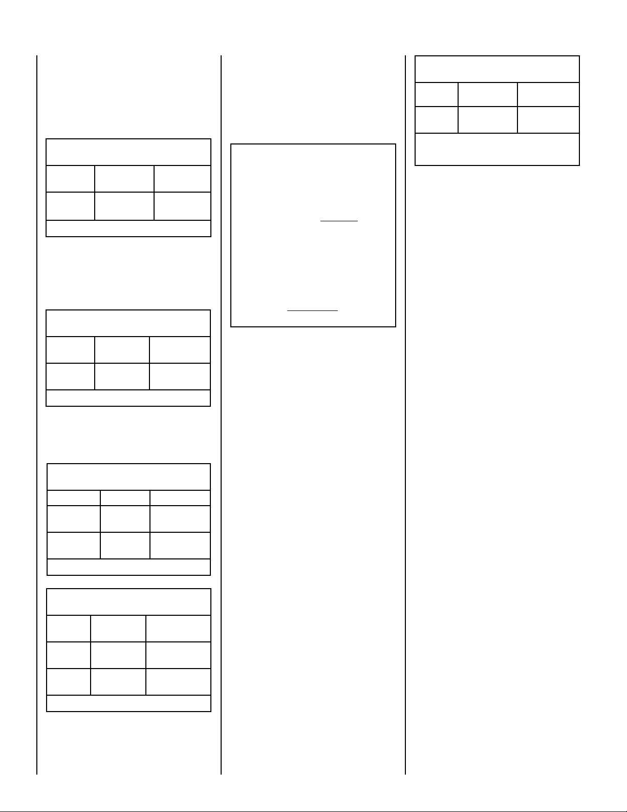
Millivolt Models - BTU Input
Millivolt models come standard with the manually-modulated gas valve; flame appearance and
heat output can be controlled at the gas valve.
The BTU Input for millivolt models is shown
in Table 1:
Input (BTU) Manually-Modulated Gas
Valves (millivolt models)
Models Fuel Type Input Rate
(BTU / HR)
SSDVST
SSDVPF
Natural or
Propane Gas
37,500 high
30,000 low
Table 1
Electronic Models -
Electronic models have a fixed rate gas valve.
The BTU Input for electronic models is shown
in Table 2:
Input (BTU) - Fixed Rate
(electronic models)
Models Fuel Type Input Rate
(BTU / HR)
SSDVST
SSDVPF
Natural or
Propane Gas
37,500
Table 2
Gas Pressure -
Tables 3 and 4 show the appliances' gas
pressure requirements.
Inlet Gas Supply Pressure
(all models)
Fuel # Minimum Maximum
Natural Gas
Propane
5.0" WC
(1.24 kPa)
11.0" WC
(2.74 kPa)
10.5" WC
(2.61 kPa)
13.0" WC
(3.23 kPa)
Table 3
Test gauge connections are provided on the
front of the millivolt gas control valve, identified IN for the inlet and OUT for the manifold
side (see Figure 3 on Page 6). A 1/8" NPT Test
gauge connection is provided at the inlet and
outlet (manifold) ports on the electronic gas
control valve (see Figure 4 on Page 6).
These appliances must be isolated
from the gas supply piping system (by
closing their individual manual shut-off
valve) during any pressure testing of
the gas supply piping system at test
pressures equal to or less than 1/2 psig
(3.5 kPa).
These appliances and their individual
shut-off valves must be disconnected
from the gas supply piping system during any pressure testing of that system
at pressures greater than 1/2 psig (3.5
kPa).
Orifice Sizes - Sea Level to High Altitude
(All Models)
These appliances are tested and approved for
installation at elevations of 0-4500 feet (0-1372
meters) above sea level using the standard
burner orifice sizes (marked with an "*" in Table
5). For elevations above 4500 feet, contact your
gas supplier or qualified service technician.
Deration - At higher elevations, the amount
of BTU fuel value delivered must be reduced
by either:
• Using gas that has been derated by the gas
company.
• Changing the burner orifice to a smaller size
as regulated by the local authorities having
jurisdiction and by the (USA) National Fuel
Gas Code NFPA 54/ANSI Z223.1 - latest
edition or, in Canada, the CAN/CSA-B149.1
codes - latest edition.
Burner Orifice Sizes
Elevation 0-4500 feet ( 0-1372 meters)
Model
Series
SSDVST
SSDVPF
Table 5
Nat.Gas
drill size (inches)
#44 (.086")
* Standard size installed at factory
** Standard size in LP conversion kit
• Part /Cat. Number
60J80 •
*
Propane
drill size (inches)
#55 (.052")
19L52 •
**
Burn-in Period
During the first few fires of this appliance there
will be some odor due to the curing of the
paint and burning off of lubricants used in the
manufacturing process. Depending on your
use, the burn-in period may take a few hours
or a few days.
KEEP YOUR HOUSE WELL VENTILATED
DURING THE CURING PROCESS. THE ODOR
AND HAZE EMITTED DURING THE CURING
PROCESS CAN BE QUITE NOTICEABLE AND
MAY SET OFF A SMOKE DETECTOR.
If an optional blower is installed, Do Not turn
it on during the Burn-In period.
A white film may develop on the glass front
during the first few fires as part of the curing
process. The glass should be kept clean during
the first two weeks of use to prevent the film from
baking on (making it very difficult to remove).
See Cleaning Glass on Page 8.
Manifold Gas Supply Pressure
(all models)
Fuel # Low
(millivolt only)
Natural
Gas
Propane
(Lo) 2.2" WC
(.55 kPa)
(Lo) 6.3" WC
(1.57 kPa)
High
(Hi) 3.5" WC
(.87 kPa)
(Hi) 10.0" WC
(2.49 kPa)
Table 4
4
Install the appliance according to the regulations
of the local authorities having jurisdiction and,
in the USA, the National Fuel Gas Code NFPA
54 / ANSI Z223.1 - latest edition or, in Canada,
the CAN/CSA-B149.1 - latest edition.
NOTE: Flame appearance will diminish 4% per
thousand feet.
NOTE: Each model has two burners and 2
Orifices.
NOTE: DIAGRAMS & ILLUSTRATIONS ARE NOT TO SCALE.
OPERATION AND CARE OF YOUR APPLIANCE
WARNING
Young children should be carefully supervised when they are in the
same room as the appliance. Toddlers, young children and others
may be susceptible to accidental contact burns. A physical barrier is
recommended if there are at risk individuals in the house. To restrict
access to a fireplace or stove, install an adjustable safety gate to keep
toddlers, young children and other at risk individuals out of the room
and away from hot surfaces.
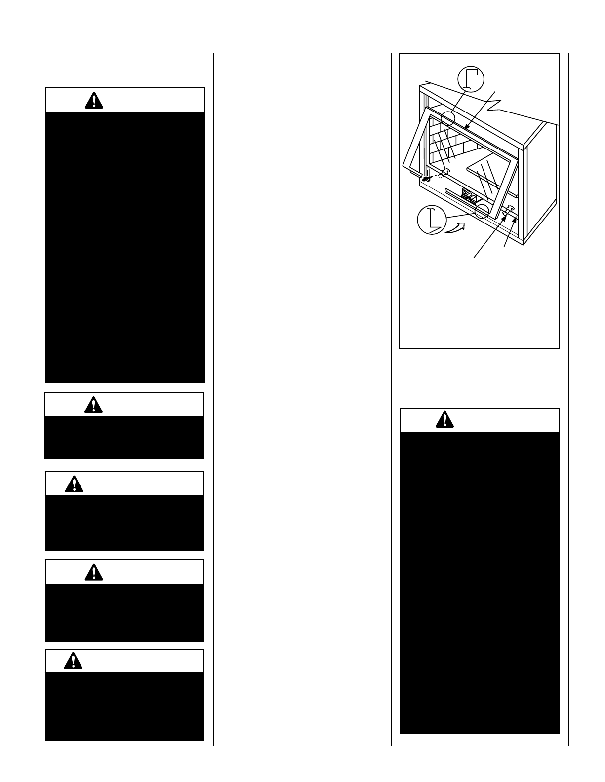
On millivolt systems, the piezo igniter, HI/LO
flame adjustment knob, and pilot and main gas
OFF/PILOT/ON control knob are located below
the glass panel enclosure. The gas valve for
electronic systems is also located below the
glass enclosure panel. See Figure 1.
Reinstalling Control Compartment Door:
To reinstall, insert the hook catches on each
side of the door into the corresponding slots
in the control compartment opening, then
gently push forward and slide down until it
locks in place.
AVERTISSEMENT
Les jeunes enfants devraient être surveillés étroitement lorsqu’ils se trouvent dans la même pièce que l’appareil. Les tout petits, les jeunes enfants
ou les adultes peuvent subir des brûlures s’ils viennent en contact avec
la surface chaude. Il est recommandé d’installer une barrière physique
si des personnes à risques habitent la maison. Pour empêcher l’accès
à un foyer ou à un poêle, installez une barrière de sécurité; cette mesure
empêchera les tout petits, les jeunes enfants et toute autre personne à
risque d’avoir accès à la pièce et aux surfaces chaudes.
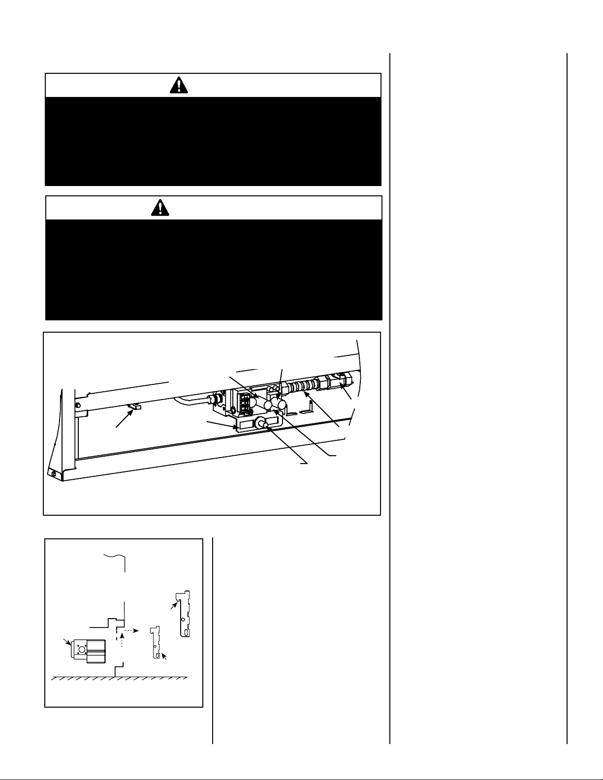
Control Compartment Access
Glass Door is Above
Control Compartment
Latch for
Glass Door
HI/LO (flame height
control knob)
Optional OFF/ON
Switch Can be
Installed Here
OFF/PILOT/ON (gas control knob)
Gas Shut-Off
Gas Flex-Line
Piezo Igniter
Gas Valve
The standard controls for appliance operation
are located behind the lower louvered control
compartment door located below the appliance
front glass enclosure panel (see Figure 1).
Optional control switches are also available (see
Page 14 - Rocker Switch, Remote Wall Switch,
Remote Control, Unit Mounted Rocker Switch
or Wall Thermostat).
Operation of millivolt and electronic gas control systems are different. Before lighting and
operating your appliance determine if you have
a millivolt or electronic appliance. Familiarize
yourself with the gas control valve that your
appliance uses. Refer to Figure 2 for access
to the gas control valve.
Millivolt Appliances - Appliances with
Millivolt systems will be fitted with the gas
control valve shown in Figure 3 on Page
6.
Electronic Appliances - Appliances with
electronic systems will be fitted with the
electronic valve shown in Figure 4 on Page
6.
Millivolt Appliances
Figure 1
OPENING CONTROL
COMPARTMENT DOOR
Control Valve
Figure 2
Lift the Lower Control
Compartment Door
up and pull out to
remove.
Hook Catch
Out
Up
Lower Control
Compartment Door
Gas Controls/Control Compartment
Access
The gas controls can be found behind the control
compartment access door.
NOTE: The top louvered panel and the bottom
louvered control compartment door will remove
and install the same way as follows:
Removing Control Compartment Door:
Open the door by gently lifting it upward until
the hook catches on both sides clear the locating
slots. Then pull door out to remove.
NOTE: DIAGRAMS & ILLUSTRATIONS ARE NOT TO SCALE.
To light millivolt appliances refer to Figure
1. Detailed lighting instructions are found on
Pages 17 and 18. Millivolt appliance lighting
instructions may also be found on the pull out
lighting instruction labels attached to the gas
control valve.
Once the pilot is lit, the main burner may be
turned ON and OFF using a wall switch, remote
control, optional on unit rocker switch (FRS), or
wall thermostat. To operate: Toggle the switch
between its ON and OFF positions.
If your millivolt appliance is equipped with an
optional remote switch kit (wall switch, remote
control, rocker switch, or wall thermostat) and
the pilot is lit, the appliance main burner may be
turned on and off using the optional switch.
Note: To prevent excessive resistance in burner
circuit (which can cause burner operation
problems), only one burner control switch
should be wired to valve.
5
F
F
O
N
I
P
S
I
NO
L
O
R
T
N
O
C
G
I
N
T
I
ER
H
I
L
O
W
H
TPT
HT
P
T
P
I
L
O
T
P
I
L
O
T
O
N
it
O
F
F
IN
OUT
Electronic Appliances -
To light electronic appliances refer to detailed
lighting instructions found on Pages 19 and
20. Electronic appliance lighting instructions
may also be found on the pull out lighting
instruction labels attached to the gas control
valve.
Once the pilot is lit, if your electronic appliance is
equipped with an optional burner control switch
kit the appliance main burner may be turned on
and off using the optional switch (See optional
accessories on Page 14 - Wall Switch, Wall
Thermostat Or Remote Control Receiver).
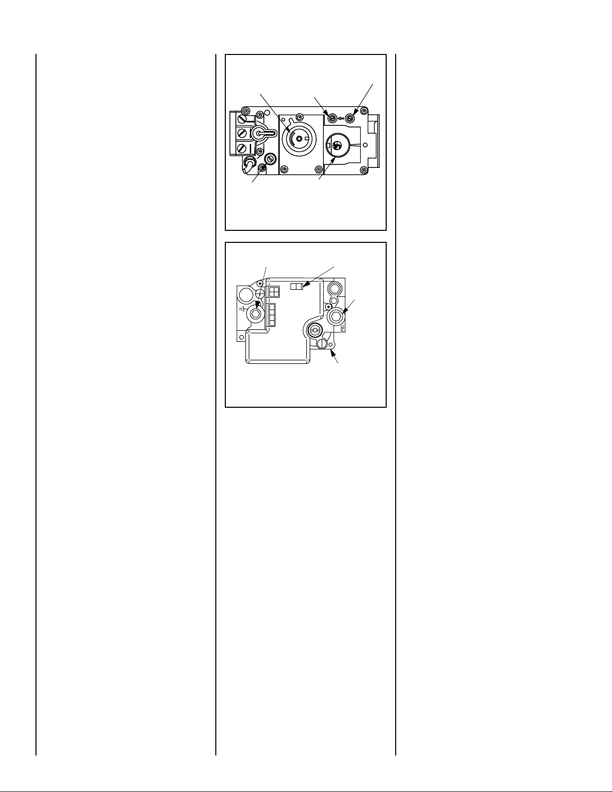
HI/LO Variable
Flame Height
Adjustment
Pilot Adjustment
Screw
Manifold Pressure Tap
Inlet Pressure Tap
Main Gas
Control Knob
OFF/PILOT/ON
Figure 3 - SIT Millivolt Gas Valve
Variable Flame Height Adjustment
(Millivolt Appliances only)
All Millivolt appliances are equipped with a
variable gas control valve. Flame height for
these models may be adjusted through a range
between fixed low and high settings while the
appliance is in operation. Adjust the flame
height as desired after lighting the appliance
by rotating the variable adjustment control
knob (HI/LO) located on the front of the valve
(refer to Figure 3).
Manifold Pressure
ON / OFF Switch
Port
Inlet
Pressure
Port
Electronic Gas
Control Valve
Figure 4 - Honeywell Electronic Gas Valve
6
NOTE: DIAGRAMS & ILLUSTRATIONS ARE NOT TO SCALE.
La chimenea caliente causará quemaduras graves
Nunca permita que los niños
toquen el vidrio ni otras
partes de la chimenea
ADVERTENCIA
Un foyer chaud peut causer
de graves brûlures
Ne laissez jamais un enfant
toucher à la vitre ou à toutes
autres parties du foyer
A
VE
R
TISSEMENT
Hot Fireplace Will Cause
Severe Burns
Never Allow Children to
Touch Glass or other Fire-
place Parts
WARNING
Hot Fireplace Will Cause
Severe Burns
Never Allow Children to
Touch Glass or other Fireplace Parts
WARNING
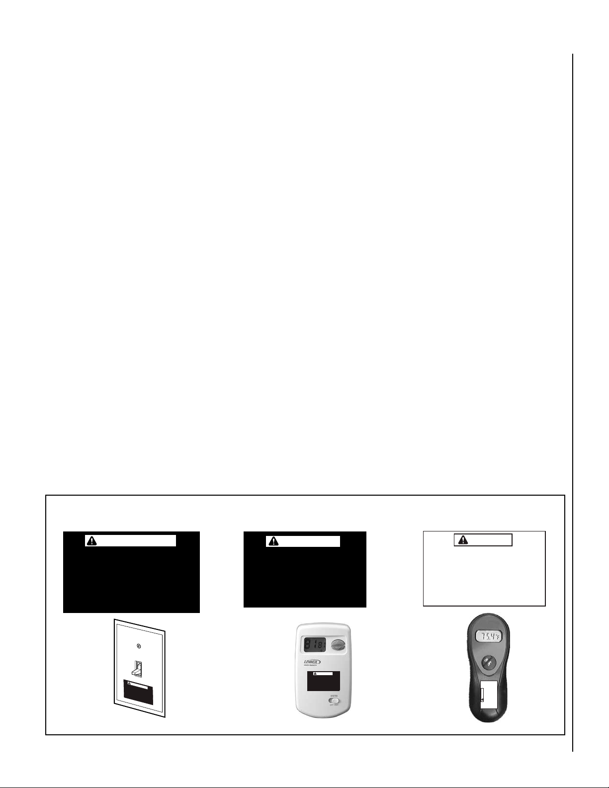
HOMEOWNER’S INSTRUCTIONS - ATTACHING SAFETY IN OPERATION WARNINGS
ATTACHING SAFETY IN OPERATION WARNINGS
Your fireplace has been furnished with safety instruction labels that are to be affixed to the operation and
control point of the fireplace. A safety instruction
label should be affixed to the wall switch plate where
the fireplace is turned on and off (See Figure A) or
wall thermostat (See Figure B) and if used on the
remote control handheld transmitter (Figure C).
The warnings should already have been put in place
when the fireplace initial set-up was completed.
If they are not affixed at these spots, locate the
multi-lingual adhesive labels provided with these
instructions and proceed as follows:
1. Locate the wall switch or wall thermostat that
controls the fireplace (verify the switch operates
the fireplace by turning it on and off). Clean the
wall switch plate or wall thermostat thoroughly
to remove any dust and oils. Affix the label to
the surface of the plate of the wall switch that
controls the fireplace (Figure A) or the wall
thermostat (Figure B). Choose the language
primarily spoken in the home.
2. If a remote control is used to control the fireplace,
locate the transmitter and clean it thoroughly
to remove any dust and oils. Affix the label to
the surface of handheld transmitter (Figure C).
Choose the language primarily spoken in the
home.
3. If you are unable to locate the labels, please call
Lennox Hearth Products or your nearest Lennox
Hearth Products dealer to receive additional
safety instruction labels free of charge.
Cat. No. H8024 Replacement Label Kit
LENNOX HEARTH PRODUCTS
1-800-9-LENNOX
Note: English is red text on clear label. French and
Spanish are white text on black label.
APPOSITION DES MISES EN GARDE RELATIVES
À LA SÉCURITÉ D’UTILISATION
Votre foyer a été livré avec des étiquettes de sécurité qui
doivent être collées à côté des dispositifs de contrôle
du foyer. Une étiquette de sécurité doit être collée sur
la plaque de l’interrupteur contrôlant l’allumage du
foyer (voir Figure A) ou sur le thermostat mural (voir
Figure B) et, le cas échéant, sur le boîtier de la télé-
commande (Figure C). Les mises en garde auraient dû
être collées au moment de l’installation initiale du foyer.
Si ce n’est pas le cas, prenez les étiquettes adhésives
multilingues fournies avec ces instructions et procédez
comme suit:
1. Repérez l’interrupteur ou le thermostat mural
qui contrôle le foyer (vérifiez que l’interrupteur
contrôle le fonctionnement du foyer en le faisant
basculer de Marche à Arrêt, et vice-versa). Nettoyez
soigneusement la plaque murale de l’interrupteur
ou le thermostat mural pour éliminer la poussière
et les traces de graisse ou d’huile. Collez l’étiquette
sur la surface de la plaque de l’interrupteur mural
qui contrôle le foyer (Figure A) ou du thermostat
mural (Figure B). Choisissez la langue qui est
principalement parlée dans la résidence du
propriétaire.
2. Si une télécommande est utilisée pour contrôler
le foyer, nettoyez la soigneusement pour éliminer
la poussière et les traces de graisse ou d’huile.
Collez l’étiquette sur le boîtier de la télécommande
(Figure C). Choisissez la langue qui est principale-
ment parlée dans la résidence du propriétaire.
3. Si vous ne trouvez pas les étiquettes, veuillez
appeler Lennox Hearth Products ou votre distributeur Lennox Hearth Products local pour recevoir
gratuitement des étiquettes supplémentaires.
Étiquettes de remplacement, n° cat. H8024
LENNOX HEARTH PRODUCTS
1-800-9-LENNOX
Remarque : Le texte anglais est rouge sur un support
transparent. Le texte français et espagnol est blanc
sur un support noir.
COLOCACIóN DE ADVERTENCIAS DE SEGURIDAD
EN OPERACIóN
Su chimenea incluye etiquetas de instrucciones
de seguridad que deben colocarse en el punto de
operación y control de la chimenea. Se debe colocar
una etiqueta de instrucciones de seguridad en la placa
del interruptor de pared desde el cual se enciende y se
apaga la chimenea (ver la Figura A) o en el termostato
de pared (ver la Figura B) y en el transmisor de control
remoto (Figura C) si se usa. Las advertencias ya deben
haberse colocado cuando se completó la instalación
inicial de la chimenea. Si no están colocadas en estos
lugares, encuentre las etiquetas adhesivas multilingües
proporcionadas con estas instrucciones y prosiga de
la siguiente manera:
1. Identifique el interruptor o el termostato de pared
que controla la chimenea (verifique que el interruptor
opera la chimenea encendiéndola y apagándola).
Limpie bien la placa del interruptor o el termostato de
pared para quitar el polvo y aceite. Pegue la etiqueta
en la superficie de la placa del interruptor que controla
la chimenea (Figura A) o en el termostato de pared
(Figura B). Seleccione el idioma que más se habla
en la casa.
2. Si se usa un control remoto para controlar la
chimenea, encuentre el transmisor y límpielo bien
para quitar el polvo y aceite. Pegue la etiqueta en la
superficie del transmisor (Figura C). Seleccione el
idioma que más se habla en la casa.
3. Si no puede encontrar las etiquetas, sírvase llamar
a Lennox Hearth Products o al distribuidor de
Lennox Hearth Products más cercano para recibir
etiquetas de instrucciones de seguridad adicionales
gratuitas.
Juego de etiquetas de repuesto - Nº de cat. H8024
LENNOX HEARTH PRODUCTS
1-800-9-LENNOX
Nota: La etiqueta en inglés es transparente con texto
rojo. Las etiquetas en francés y español son negras
con texto blanco.
Un foyer chaud peut causer
de graves brûlures
Ne laissez jamais un enfant
toucher à la vitre ou à toutes
autres parties du foyer
Figure A
DIAGRAMMES DES ÉTIQUETTES DE SÉCURITÉ / DIAGRAMAS DE ETIQUETAS DE SEGURIDAD / SAFETY LABEL DIAGRAMS
AVERTISSEMENT
ADVERTENCIA
La chimenea caliente
causará quemaduras graves
Nunca permita que los niños
toquen el vidrio ni otras
partes de la chimenea
Figure B
NOTE: DIAGRAMS & ILLUSTRATIONS ARE NOT TO SCALE.
Figure C
7
MAINTENANCE
(See Maintenance Schedule, Page 21)
Refer to the maintenance schedule for maintenance tasks, procedures, frequency and
by whom they should be performed. Always
verify proper operation of the appliance after
servicing.
WARNING
Turn off gas and electrical power
to the fireplace and allow it to
cool before cleaning or servicing
the appliance.
CAUTION: Wear gloves and safety
glasses for protection while doing
required maintenance.
Verify proper operation after servicing.
S'assurer que l'appareil fonctionne adéquatement une fois l'entretien terminé.
Always turn off gas to the pilot (millivolt
appliances) before cleaning. Before relighting, refer to the lighting instructions
in this manual. Instructions are also found
on a pull-out panel located in the control
compartment.
Inspect Venting System
The appliance and venting system should be
thoroughly inspected before initial use and
at least annually by a qualified service technician (inspection should include ensuring that
exhaust or intake passages are unobstructed
and vent components are properly assembled
and not damaged). Homeowner must contact
a qualified service technician at once if any
abnormal condition is observed.
If the venting system is disassembled for any
reason, a qualified service technician should
follow vent installation instructions for proper
reassembly and proper sealing of the venting
system components. However, more frequent
periodic inspections and cleanings should be
performed by the homeowner.
Cleaning Glass
(see Front Glass Enclosure Panel, Removal and
Installation on Page 9).
Note: Clean glass after first two weeks of opera-
tion (after Burn-In period is over) and then only
when necessary and when the fireplace is cool.
Wipe surface with clean, dampened, soft cloth.
Follow with a dry, soft towel as desired. Take
care not to scratch the glass surface.
IMPORTANT: Do not use abrasive cleaners on glass. Never clean the glass when
it is hot.
The viewing glass should be cleaned periodically to remove any build-up caused from the
following:
• During start-up, it is normal for condensa
tion to form on the inside of the glass (this
condensation and fog will usually disappear
in a few minutes). The moisture can cause
lint, dust and other airborne particles to cling
to the glass surface.
• Initial curing of the high temperature paint
and burning off of lubricants used in the
manufacturing process may result in a film
on the glass.
• A white coating may form on the glass as
a result of impurities and minerals in the
fuel.
It is recommended that the glass be cleaned
two or three times during each heating season,
depending on the circumstances present. The
following cleaning solutions are approved for
use to clean glass:
• Non-ammonia based household cleaner
• 50%-50% mix of white vinegar and water
• Gas fireplace/stove glass cleaner
Inspect Glass Gasket - Visually inspect the
gasket on the backside of the glass enclosure
panels. The gasket surface must be clean, free
of irregularities and seated firmly.
Clean Control Compartment
Keep control compartment clean by vacuuming
or brushing at least twice a year. More frequent
cleaning may be required due to excessive lint
from carpeting, bedding materials, etc. It is
important that control compartments, burners
and circulating air passageways of the appliance
be kept clean.
Clean Logs And Burner
Carefully remove the logs (use care when handling the fiber logs, as they become quite fragile
after curing). Vacuum out any foreign matter
(lint, carbon, etc.) on the burner. Ensure the
burner ports are “open.” Remove any carbon
deposits from the under side of the logs using
a vacuum cleaner, or a soft bristled brush (i.e.
paint brush).
Replacing Logs
If the logs become damaged by accident or
improper handling and need replacement,
use only the proper replacement logs from
manufacturer (see Page 24 for ordering
information).
Re-Install Embers, Logs and Volcanic Stone
Carefully follow placement instructions on
Page 10. All logs should fit onto corresponding pins and/or log stoppers. This will ensure
a proper flame and safe combustion.
Inspect Wiring
Refer to wiring diagrams on Page 13.
CAUTION: Label all wires prior to disconnection when servicing controls. Wiring
errors can cause improper and dangerous
operation. Verify proper operation after
servicing.
ATTENTION: Au moment de l'entretien
des commandes, étiquetez tous les fils
avant de les débrancher. Des erreurs
de cáblage peuvent entraîner un fonctionnement inadéquat et dangereux.
Inspect and clean all wire connections. Ensure
that there is no melting or damage. Inspection
should include:
• Terminals at the Valve
• OFF/ON Switch
• (Optional Control Switch) Wall Thermostat,
Remote Control or Remote Wall Switch Kit
Inspect Burner Flame Appearance
Ensure that the burner flame appearance
resembles the flame shown in Figures 7 and
10 and as described in Flame Appearance and
Sooting on Page 11. The Homeowner must
contact a qualified service technician at once
if any abnormal condition is observed.
Small Area Paint Touch-up
Only use a factory supplied paint kit for
touch-ups. Paint is available at your local
authorized LHP dealer. Never attempt to paint
a hot fireplace.
If the surface later becomes stained or marred,
it may be lightly sanded and touched up with
spray paint.
Note: Improper positioning of logs can create
carbon build-up and will alter the performance
8
of the appliance.
Front Glass Enclosure Panel, Removal
and Installation
WARNING
• Do not attempt to substitute the
materials used on this door,
or replace cracked or broken
glass.
• Handle this glass with extreme
care! Glass is susceptible to
damage – Do not scratch or
handle roughly while reinstalling the glass door frame.
• The glass door of this appli-
ance must only be replaced
as a complete unit as provided
by the manufacturer. Do not
attempt to replace broken,
cracked or chipped glass separately.
• Do not attempt to touch the
front enclosure glass with your
hands while the fireplace is in
use.
WARNING
Do not operate appliance with
the glass front removed, cracked
or broken.
AVERTISSEMENT
Ne pas utiliser l'appareil si le
panneau frontal en verre n'est
pas en place, est craqué ou
brisé.
WARNING
Any safety screen or guard
removed for servicing the appliance must be replaced prior to
operating the appliance.
AVERTISSEMENT
Tout écran ou protecteur retiré
pour permettre l’entretien de
l’appareil doit être remis en
place avant de mettre l’appareil
en marche.
Only doors certified with the appliance
shall be used.
Seules des portes certifiées pour cet
appareil doivent être utilisées.
CAUTION: DO NOT abuse glass door by
striking or slamming shut.
These are direct-vent appliances. They are
designed to operate only when the front glass
enclosure panels are installed. Generally the
front glass enclosure panel should not be removed except to gain access to the components
within the firebox.
Removing Glass Enclosure Panels
(see Figure 5)
1. Remove the top louver assembly the control
compartment louver assembly by lifting them
up, then pulling out (see Figure 2 on Page
5).
2. Locate the two (2) latches at the top of the
control compartment. To disengage the two
latches from the bottom vee-flange of the
glass enclosure panel, reach for the handles
located towards the back of the latches and
pull the handles down toward the front of
the appliance.
3. Swing the bottom of the door out and raise
it slightly to lift the top flange of the door
frame away from the appliance.
Installing Glass Enclosure Panels
(see Figure 5)
1. Visually inspect the gasket on the backside of
the panels. The gasket surface must be clean,
free of irregularities and seated firmly.
2. Position the glass enclosure panel in front
of the firebox opening at a 45 degree angle
and engage the top flange over the lip at the
top of the firebox opening.
3. Swing the glass enclosure panel down and
back. Ensure the gasket seats evenly as the
panel draws shut. Engage the Vee-flange at
the bottom of the panel with the latches and
close the latches to secure the panel.
4. Reinstall the lower control compartment
door (see Figure 2 on Page 5).
NOTE: DIAGRAMS & ILLUSTRATIONS ARE NOT TO SCALE.
Top Flange on
Glass Door
Glass Door
Bottom Vee-flange
Glass Door
Glass Door Latch
Note: When installing the glass door, ensure the
spacing on both sides are equal.
Figure 5
INSTALLING OR REMOVING GLASS DOOR
INSTALLING LOG SET, VOLCANIC STONE
AND GLOWING EMBERS
Firebox Floor
WARNINGS
• DO NOT attempt to install the
logs until the appliance installation has been completed, the
gas line connected and tested
for leaks and the initial burner
operation has been checked
out.
• The size and position of the log
set was engineered to give the
appliance a safe, reliable and
attractive flame pattern. Any
attempt to use a different log
set in the fireplace will void
the warranty and will result in
incomplete combustion, sooting, and poor flame quality.
• Logs get very hot and will
remain hot up to one hour
after gas supply is turned off.
Handle only when logs are
cool. Turn off all electricity
to the appliance before you
install grate, volcanic stone,
embers and logs.
9
 Loading...