

Page 1
Installation and Operation Instructions
PFS
Superior® Clean-Face Round Back Fireplace
with Bi-Fold Doors and Combustion Air Kit
P/N 127312-01 Rev. D 10/2025
®
P127312-01
USC
Models
MHW36R
SAVE THIS BOOK
This book is valuable. In addition to instructing you on how to install and maintain your appliance, it also
contains information that will enable you to obtain replacement parts or accessory items when needed. Keep
it with your other important papers.
INSTALLER: Leave this manual with the appliance.
CONSUMER: Retain this manual for future reference.
Installateur : Laissez cette notice avec l’appareil.
Consommateur : Conservez cette notice pour consultation ultérieure.
This wood burning fireplace complies with UL127
CAN/ULC-S610-M87 standard as a FACTORY
BUILT FIREPLACE.
This fireplace is approved for use as a wood burning fireplace or for use with a vented gas log approved to
ANSI Z21.60 or Z21.84 standards or for use with a vent-free gas log heater approved to ANSI Z21.11.2 standard
An IHP hood must be installed when using a vent-free log heater (see Accessories, page 19).
FOR CANADA: The authority having jurisdiction
(such as the municipal building department, fire
department, etc.) should be contacted before
installation to determine the need to obtain a permit.
This installation manual will enable you to obtain a safe, efficient and dependable installation of your fireplace
system. Please read and understand these instructions before beginning your installation.
Do not alter or modify the fireplace or its components under any circumstances. Any modification or alteration of
the fireplace system, including but not limited to the fireplace, chimney components and accessories, may void the
warranty, listings and approvals of this system and could result in an unsafe and potentially dangerous installation.
IMPORTANT! TO ASSURE PROPER ALIGNMENT OF GLASS DOORS: INSTALL THIS FIREPLACE IN A SQUARE
AND PLUMB CONDITION, USING SHIMS AS NECESSARY AT SIDES AND/OR BOTTOM.
Ce foyer au bois est conforme aux UL 127 CAN/ULCS610-M87 norme comme une USINE CONSTRUITE
CHEMINÉE.
.
POUR LE CANADA: L’autorité compétente (comme le
service municipal du bâtiment, les pompiers, etc.) doit
être contacté avant l’installation afin de déterminer la
nécessité d’obtenir un permis.
Page 2
TABLE OF CONTENTS
Safety ................................................................................................... 2
Fireplace Installation ............................................................................ 2
Venting Installation .............................................................................. 6
Optional Gas Line Installation ............................................................ 13
Finishing Fireplace ............................................................................. 15
Operation and Maintenance Guidelines .............................................. 15
Technical Service ...............................................................................17
Replacement Parts ............................................................................. 17
Accessories ........................................................................................ 18
Important Notices .............................................................................. 21
Warranty ............................................................................................ 23
CAUTION
Thestructural integrityof the mobilehome oor
and ceiling/roof must be maintained.
WARNING
Do not install a fireplace insert in this box unless
the manufacturer's instructions with the insert
specifically state this fireplace has been tested for
use with the insert.
FOR YOUR SAFETY
SAFETY
WARNING
Improper installation, adjustment, alteration,
service or maintenance can cause injury, property
damage or loss of life. Refer to this manual for
assistance or additional information. Consult a
qualified installer or local distributor.
IMPORTANT: Check HUD requirements before installing this
fireplace.
These units are intended for installation in manufactured (mobile) homes.
These units may also be installed in buildings of conventional construction
including modular housing, providing all instructions provided herein
are strictly adhered to. These fireplaces include a combustion air kit and
bi-fold doors.
Before beginning the installation of the fireplace, read these instructions
through completely.
• ThisIHPreplaceanditscomponentsaresafewheninstalledaccord-
ingtothisinstallationmanual.UnlessyouuseINNOVATIVEHEARTH
PRODUCTS(IHP)approvedcomponents,whichhavebeendesigned
and tested for the fireplace system, you may cause a fire hazard.
• TheIHPwarrantywillbevoidedbyandIHPdisclaimsanyresponsibility for the following actions.
a. Modification of the fireplace, components, doors, air inlet system and
damper control.
b. UseofanycomponentpartnotmanufacturedorapprovedbyIHP
incombinationwithanIHPreplacesystem.
• Donotstoreorusegasolineoranyotherammablevapors
or liquids in the vicinity of this or any other appliance.
• Duetohightemperatures,theapplianceshouldbelocated
out of traffic and away from furniture and draperies.
• Donotplaceclothingorotherammablematerialsonor
near the appliance.
• Neverleavechildrenunattendedwhenareisburningin
the fireplace.
This fireplace is not intended to be used as a substitute for a
furnace to heat an entire home. Use for supplemental heat only.
This wood burning fireplace complies with the UL 127 standard
as a FACTORY BUILT FIREPLACE and is listed and tested by the
PFS Corporation.
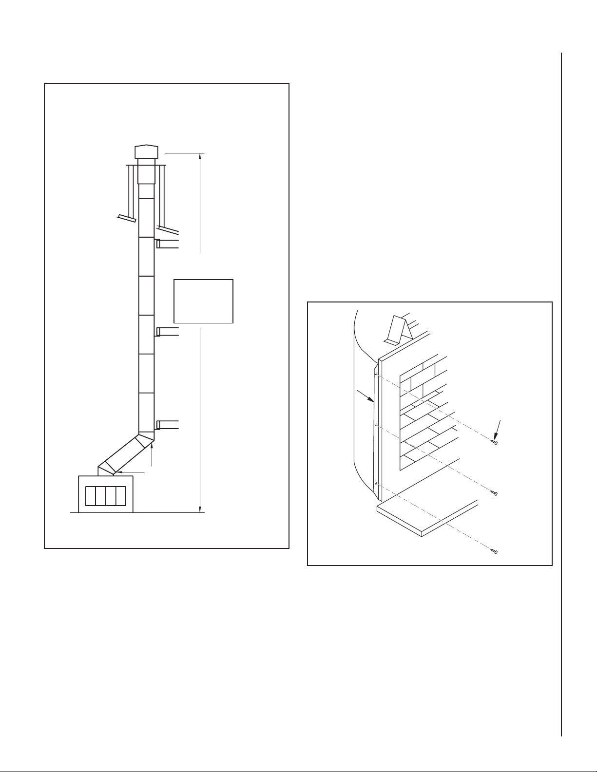
FIREPLACE INSTALLATION
SELECTING LOCATION
To determine the safest and most efficient location for the fireplace, you
must take into consideration the following guidelines:
1. The location must allow for proper clearances (see Figures 2 and 3,
page 4).
2. Consider a location where the heat output will not be affected by
drafts, air conditioning ducts, windows or doors.
3. A location that avoids the cutting of joists or roof rafters will make
installation easier.
4. An outside air kit is included with this fireplace (see Outside Air Kit on
page 6)
WARNING
Proper installation is the most important step in ensuring safe and continuous operation of the fireplace. Consult the local building codes as to
the particular requirements concerned with the installation of all factory
built fireplaces.
SuperiorFireplaces.US.com 127312-01D2
Do not install this appliance in a bedroom.
Page 3
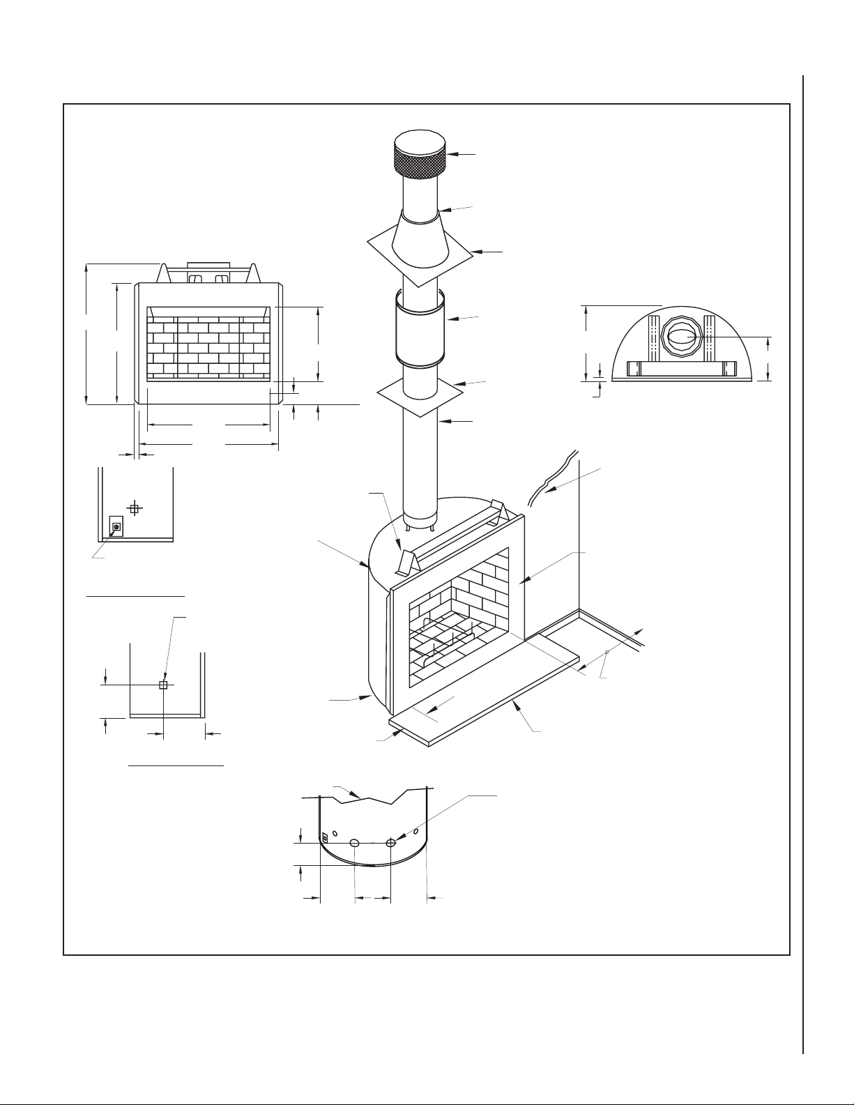
SPECIFICATIONS
Round Top Termination
Storm Collar
Flashing
42"
1
/4"
36
J-Box
Access
RH SIDE VIEW
3
7
/4"
36"
1"
41"
Gas Line Conduit
Sleeve (Both Sides)
22
3
6
3"
0" To Top
1/2" Air Space
Back and Sides
0" To
Bottom
1
/8"
/4"
Spacer
Firestop
Thimble
221/16"
13"
Firestop
5/8"
1" Airspace
To Combustible
Materials
Combustible
Wall Board
No Combustible
Material On Face
Not Less Than 14"
To Perpendicular
Sidewall
3
9
LH SIDE VIEW
Figure 1 - Specifications
127312-01D
/8"
Rear View
of Fireplace
91/2"
8" Each
Side
14"
14"
SuperiorFireplaces.US.com
Hearth Extension
52" x 16"
Opening for
Outside Air
3
Page 4
FIREPLACE INSTALLATION
Effective Height of
Termination Cap
RT-8DM
30E-8DM
40' Max.
Height
20' for
Manufactured
Home
Application
Continued
WARNING
42 1/4"
3
41
/4"
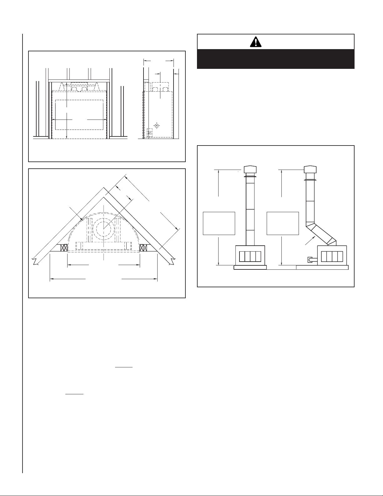
Figure 2 - Framing Dimensions
Maintain 1/2" Air Space
between surface of
Maintain 1/2" Air Space
framing, insulation, and
Between Framing
drywall.
and Fireplace
13" Min.
43
22
Min.
5
/8"
10"
Do not pack required air spaces with insulation or
other materials.
MINIMUM/MAXIMUM CHIMNEY HEIGHT
Minimum height of the chimney, measured from base of fireplace to flue
gas outlet of termination, is 14 feet* for straight flue or a flue with one
elbow set. Maximum distance between elbows is 2 feet.
Maximum height of any system is 40 feet.* This measurement includes
fireplace, chimney sections and height of termination assembly at level
of flue gas outlet (see Figure 5).
Effective Height of
Termination Cap
5
/8"
14' Min.
Height
11' for
Manufactured
Home
Application
RT-8DM
Effective Height of
Termination Cap
14' Min.
Height
11' for
Manufactured
Home
Application
RT-8DM
41 3/4" Min.
61
11/16" Min.
Figure 3 - Corner Installation
MINIMUM CLEARANCE TO COMBUSTIBLES
Back and sides of fireplace 1/2" minimum*
Floor under fireplace** 0" minimum
Wall to front of fireplace 36" minimum
Perpendicular wall to opening 14" minimum
Top spacers 0" minimum
Mantel clearances see Mantels, page 15
Chimney outer pipe surfaces 1" minimum
* Not required at nailing flanges
** See step 2 of Framing, page 5
2' Max
Pipe Length
Figure 4
*For manufactured home application, minimum height is 11' for straight
flue or flue with one elbow set. Maximum height of any system is 20'.
SuperiorFireplaces.US.com 127312-01D4
Page 5
FIREPLACE INSTALLATION
Continued
Standard
Installation
RT-8DM
Alternate
Installation
Effective Height of
Termination Cap
40' Max.
Height
20' for
Manufactured
Home
Application
FRAMING
1. Frame opening for fireplace using dimensions shown in Figures 2
and 3.
2. The fireplace may not be installed on carpeting, tile or any combustible
material other than wood flooring, fireplace must be installed on a
metal or wood panel extending full width and depth of fireplace. (It is
acceptable to cover two outside ends or columns of top louver panel
leaving four center columns open).
3. Set fireplace directly in front of this opening and slide unit back until
nailing flanges touch side framing.
4. Check level of fireplace and shim with sheet metal if necessary.
5. Before securing fireplace to prepared framing, metal ember protector
(provided) must be placed between hearth extension (not supplied)
and under bottom front edge of fireplace to protect against glowing
embers falling through. If fireplace is to be installed on a raised platform, a Z-type ember protector (not supplied) must be fabricated to fit
your required platform height. Ember protector should extend under
fireplace a minimum of 1-1/2". The ember protector should be made
of metal material.
6. Using screws or nails, secure fireplace to framing through flanges
located on sides of fireplace (see Figure 6).
Alternate
30E-8DM
Installation
Figure 5 - Standard and Alternate Venting Installation
Nailing
Flange
Screw or
Nail
Figure 6 - Nailing Flanges
127312-01D
SuperiorFireplaces.US.com
5
Page 6
FIREPLACE INSTALLATION
Continued
HEARTH EXTENSION
A hearth extension projecting a minimum of 16" in front of and a minimum
of 8" beyond each side of the fireplace opening is required to protect
combustible floor construction in front of the fireplace. Use an equal material which meets the following specifications: a layer of noncombustible,
inorganic material having a thermal conductivity of k = .84 BTU IN/FT2
HR°F(orless)at1"thick.Forexample,ifthematerialselectedhasak
factor of 0.25, such as glass fiber, the following formula would apply:
0.25 x 1.0" = 0.30" thickness required
0.84
Thermal conductivity "k" of materials can be obtained from the manufacturer or supplier of the noncombustible material. If the hearth extension
is to be covered, use noncombustible material such as tile, slate, brick,
concrete, metal, glass, marble, stone, etc. Provide a means to prevent
hearth extension from shifting and seal gap between fireplace frame and
hearth extension with a noncombustible material (see Figure 7).
Fireplace
Front
Ember
Protector
Fireplace Front
Elevated
Seal Gap
Seal Gap
Ember
Protector
Hearth
Extension
WARNING
Hearth extension is to be installed only as shown
in Figure 7.
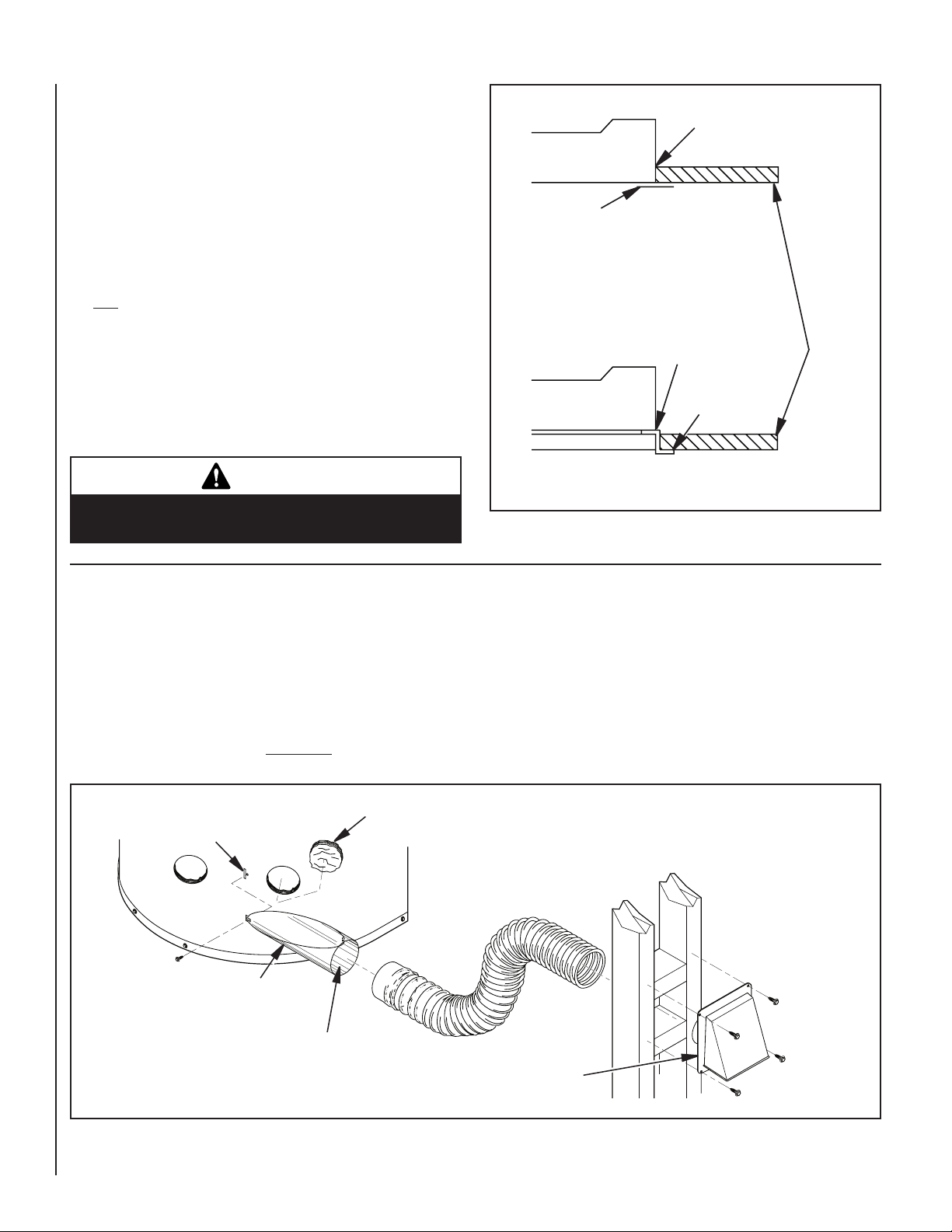
VENTING INSTALLATION
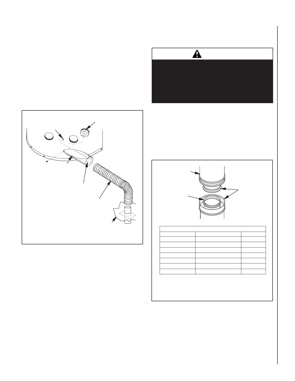
OUTSIDE AIR KIT
Installation of an outside air kit should be completed during the rough
framing of fireplace due to nature of its location. The supplied flex duct
measures approximately 10" compressed and up to approximately 36"
extended. Outside combustion air is accessed through mobile home floor
using air kit model AK6E, included with the fireplace, or a side wall using
optional air kit model AK6-WE (see Accessories on page 19).
Insert Inner Tab of Inlet Tube into
Slot on Outer Surround
Insulation
Figure 7 - Hearth Extension
Installer may choose either left or right side mounting to allow for
proper wall/rafter clearances.
For AK6-WE Only: Construct a 4-1/2" x 4-1/2" framing or opening on
exterior wall (see Figure 8, page 6).
For AK6E Only: The outside air vent is installed through a ventilated crawl
space (see Figure 9, page 7).
Air Vent Location Must
Allow for Bushes, Snow
and Other Possible
Obstructions
Left Side
Mounting Shown
Secure to Collar with Metal
Tape, Screws or Tie Straps
Figure 8 - Outside Air Kit AK6-WE Installation
Outside Air Vent
Termination
SuperiorFireplaces.US.com 127312-01D6
Page 7
VENTING INSTALLATION
Continued
1. Locate and remove air inlet cover plate on fireplace‘s outer surround.
Save screws.
2. Cut out any visible insulation that may obstruct airflow.
3. Extend flex duct to attach air inlet tube.
4. Insert inner tab of inlet tube into mating slot next to opening.
5. Place outer tab of inlet tube over mating hole next to opening
and secure with screws removed from cover plate in step 1.
6. Install outside air vent termination in a location that will not be
obstructed by bushes, snow, etc. Locate vent near the fireplace
to make flex duct installation easier.
Insert Inner Tab of Inlet Tube
into Slot on Outer Surround
Left Side
Mounting Shown
Insulation
CHIMNEY PIPE
WARNING
Label part number 900599-01 must be applied
by the installer to all chimney pipe sections but
is not required on sections that will be visible
after the installation is complete. Label must
wrap around the circumference of the pipe. See
accessories, page 19 for Kit F2659.
The chimney system approved for this fireplace consists of 12", 18", 24",
36" and 48" snap-lock, double-wall pipe segments, planned for maximum
adaptability to individual site requirements. Actual lengths gained after
fitting overlaps must be taken into consideration (lineal gain) and are
given in the lineal gain chart (see Figure 10). Lineal Gain is the actual
measurable length of a part after two or more parts are connected.
12-3/8" Galvanized
Outer Pipe
Secure to Collar with Metal
Tape, Screws or Tie Straps
Flex Duct Extends
Up to 36"
Figure 9 - Outside Air Kit AK6E Installation
Floor
Hemmed End
8" Stainless
Inner Pipe
LINEAL GAIN
PART NO. DESCRIPTION GAIN
MHW36R Fireplace 42
12-8DM Pipe Section 10-5/8
18-8DM Pipe Section 16-5/8
24-8DM Pipe Section 23-5/8
36-8DM Pipe Section 34-5/8
48-8DM Pipe Section 46-5/8
RTL-8DM Round Termination 7-3/4
* The lineal gain for the terminations is measured to the flue gas
outlet height.
Figure 10 - Lineal Gain
"
"
"
"
"
"
*
"
127312-01D
SuperiorFireplaces.US.com
7
Page 8
VENTING INSTALLATION
Continued
There are three vent kits available which have been specially designed
for common installations in manufactured (mobile) homes: MW8K (8'
ventkit),MW9K(9'ventkit)andMW8K-HT(8'HTventkit).Contentsof
these kits are listed under Accessories on page 20. IMPORTANT: If height
of chimney assembly exceeds requirements for transportation of home,
chimney installation may be completed after home is sited.
NOTE: Termination must always be installed after the home is sited.
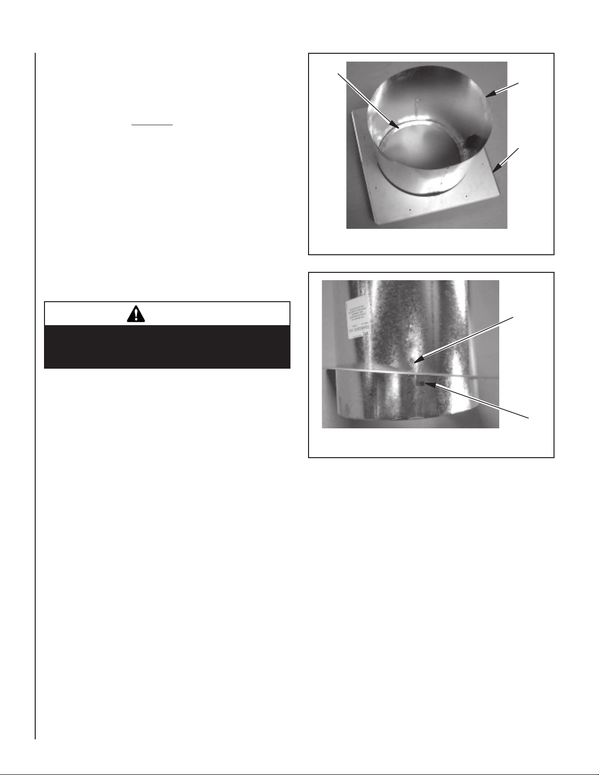
ASSEMBLY AND INSTALLATION OF DOUBLE WALL CHIMNEY
SYSTEM
Each double wall chimney section consists of a galvanized outer pipe, a
stainless steel inner flue pipe and a wire spacer. Pipe sections must be assembled independently as chimney is installed. When connecting chimney
directly to fireplace, inner flue pipe section must be installed first with lanced
side up. Outer pipe section can then be installed over flue pipe section with
hemmed end up. Press down on each pipe section until lances securely
engage hem on fireplace starter. The wire spacer will assure proper spacing
between inner and outer pipe sections.
WARNING
The opening in the collar around the chimney at the
top of the fireplace must not be obstructed. Never
use blown insulation to fill the chimney enclosure.
Flange
End of
Tube
Open End
of Tube
Thimble
Base
Figure 11 - Attaching Adjustable Thimble
Placement
Holes
Continue to assemble chimney sections as outlined above, making sure
that both inner and outer pipe sections are locked together. When installing double wall snap-lock chimney together, it is important to assure that
the joint between chimney sections is locked. Check by pulling chimney
upward after locking. Chimney will not come apart if properly locked. It
is not necessary to add screws to keep chimney together (exception, see
Figure 16, page 11).
ADJUSTABLE FIRESTOP THIMBLE
This adjustable thimble adjusts to the most commonly used ceiling
pitches automatically. Refer to the following procedure for installing the
adjustable thimble:
The adjustable thimble may be installed around the chimney components
at assembly or the chimney components may be inserted though the
installed thimble.
Install the thimble from below a finished roof and ceiling assembly. Push
the thimble assembly (tube section first) up into an already prepared opening and secure open end of the thimble base to the finished underside of
the roof and ceiling assembly (Figure 11).
Note: The two screws on which the thimble base pivots may be removed
and reinstalled into any of the series of placement holes provided for the
adjustment of the adjustable thimble's point of rotation (Figure 11A).
Adjust the pivot screens to locate the open end of the tube section as
required for the roof line. Additional screws may be placed at the high
and low points of the thimble base in the tabs provided.
Place the thimble base against the finished roof and ceiling assembly and
secure it to the framing with screws or nails. The thimble is self-adjusting
around inserted chimney components. Thimble extensions are available
and may be installed into the adjustable thimble's tube section as needed
to extend the thimble through the roof-line. Secure the thimble extension
to the tube section with screws no more than 1/2" in length.
Pivot
Screw
Figure 11A - Attaching Adjustable Thimble
Position appropriate thimble/firestop spacer combination at ceiling and
nail temporarily with two (2) 8d nails or equivalent fasteners (see Figures
12A, 12B and 12C). Use one fastener on opposite sides to hold thimble/
firestop spacercombination in position. Nail permanently, using at least
two (2) more fasteners, after chimney sections have been assembled
through the thimble/firestop spacer combination and after any necessary adjustments
have been made. Firestop spacer must be secured by at least four (4)
fasteners when completely installed.
Note: If there is a room above ceiling level, firestop spacer must be
installed on the bottom side of the ceiling. If an attic is above ceiling
level, firestop thimble must be installed on the bottom side of ceiling
joist (Figure 12).
Note: The installation of the thimble extension is not required in manufactured homes having ventilated attic spaces, when the chimney height
is equal to or greater than 12 feet.
Ensure the thimble penetrates the roof opening. The thimble must extend
completely through the ceiling or roof cavity to the outermost plane of
the roof. Note: Thimble extensions are available from your dealer for
constructions in which the distance between the outside of the roof and
the inside of the ceiling exceeds 13". The thimbles and their extensions
provide for zero clearances to combustibles and must be used at the
ceiling/roof in manufactured homes (see Figures 12B and 12C, page 9).
SuperiorFireplaces.US.com 127312-01D8
Page 9

"
VENTING INSTALLATION
Continued
Room Above
WARNING
Do not allow insulating materials to be blown into
the space inside the thimble and the chimney. To
do so could result in a fire hazard.
Attic Above
14" Min.
Note: Trim Thimble/
Extension To Desired Length
And Pitch At The Rood Line
Figure 12
Figure 12A
Thimble
Extension
Pitched Roof
Firestop Spacer
Firestop Thimble
Outer Pipe Of
Chimney
Thimble
FM8-AT1
Pitched Roof
14" Min.
Thimble
1" Clearance
Minimum
Outer Pipe Of
Chimney
Outer Pipe Of
Chimney
14" Min.
Thimble Cathedral
Ceiling
Figure 12C
PENETRATING ROOF
To maintain a 1" clearance to pipe on a roof with a pitch, a rectangular
opening must be cut.
1. Determine center point through which pipe will penetrate the roof.
2. Determine center point of the roof. Pitch is the distance the roof drops
over a given span, usually 12". A 6/12 pitch means that the roof drops
6" for each 12" measured horizontally down from roof rafters.
3. Use roof opening chart (Figure 13) to determine correct opening
length and flashing required.
4. Remove shingles around opening measured. Cut out this section.
5. Add next sections of pipe until end penetrates roof line. Check to see
that proper clearances are maintained. Extend chimney by adding
sections of double wall pipe until pipe is minimum of 30" above
highest point of roof cutout. Termination and chimney must extend
a minimum of 36" above highest point where it passes through roof.
Minimum Measurements
14 3/8"
(36.5 cm)
1"
(2.5
cm)
13
30"
(76.2 cm)
1"
(2.5 cm)
1"
(2.5
cm)
127312-01D
14" Min.
Outer Pipe Of
Chimney
Thimble
Bow Roof
Figure 12B
SuperiorFireplaces.US.com
Opening "A"
PITCH SLOPE OPENING "A" MAX FLASHING MODE NO.
Flat 0° 15" 6F-8
0-6/12 26.6° 16-1/8" 6F-8
6/12 - 12/12 45° 20-3/8" 12F-8
Figure 13 - Determine Roof Opening
9
Page 10

VENTING INSTALLATION
Continued
USING ELBOW OFFSETS (30E-8DM)
1.
To achieve desired offset, you may install combinations of 12", 18",
24", 36" and 48" length of double wall pipe (see offset chart and
Figure 14).
OFFSET RISE CHIMNEY LENGTH
A B 48" 36" 24" 18" 12"
4 3/8" 16 3/8"
ELBOW SET ONLY
9" 25 3/4" 1
11 7/8" 31" 1
15" 37 3/8" 1
16 3/4" 40 1/2" 1 1
20" 47 1/8" 1
22 5/8" 52 1/8" 1 1
25 1/2" 57 7/8" 1
27 5/8" 62" 1 1
30 3/8" 67 1/4" 1 1
33" 72 5/8" 1 1
35 3/4" 78" 2
37 7/8" 82" 1 1 1
41 1/4" 88 5/8" 1 1
43 3/8" 92 3/4" 2 1
46 5/8" 99 3/8" 2
48 3/4" 103 1/2" 1 1 1
51 1/2" 108 7/8" 2 1
54 1/4" 114 1/8" 2 1
57" 119 1/2" 1 2
59" 123 5/8" 2 1 1
61 3/4" 129" 1 2 1
64 1/2" 134 3/8" 1 2 1
67 1/4" 139 5/8" 4
2. Chimney weight above offset rests on return elbow. Straps must be
securely nailed to rafters or joists (see Figure 15, details A and B).
3. Maximum length of pipe between supports (return elbow or 12S-8DM)
is 6' of angle run. Maximum of two 6' angle run sections per chimney
system (see Figure 14).
4. All pipe connections between offset and return must be secured with
two screws on outer pipe only (see Figure 16). Do not penetrate inner
stainless.
See Detail A
Straps
Straps
Detail B
Angle Firestop
Straps
Detail A
Return Elbow
Figure 15 - Ceiling Support Pipe 12S-8DM
Straps
See Detail B
OFFSET CHART (22-50 FT. SYSTEM HEIGHT)
Screws
Figure 14 - Elbow Offset
B
A
SuperiorFireplaces.US.com 127312-01D10
Page 11

VENTING INSTALLATION
Continued
Return
Elbow
Offset Elbow
6' Max.
Return
Elbow
6' Max.
Offset Elbow
Offset Elbow
A
Offset Elbow
Return
Elbow
6' Max.
Offset Elbow
6' Max.
B
Figure 16 - Typical Offset Terminations (For Systems with 2 Elbow Sets, Maximum Height is 20')
FIRESTOP SPACERS (3600FS-8DM-1)
Firestop spacers are required at each point where the chimney penetrates a
floor space. Their purpose is to establish and maintain the required clearance
Storm Collar
Flashing
Cone
between the chimney and the combustible materials. When the pipe passes
through a framed opening into a living space above, the firestop must be
placed onto the ceiling from below as shown in Figure 17.
Nail Only Outer
Perimeter of
Flashing
Return
Elbow
Ceiling Support Pipe
12S-8DM
Return
Elbow
6' Max.
6' Max.
C
Overlap Shingles Top
and Sides Only
Existing
Ceiling Frame
Firestop
Spacer
Screws or Staples
(Min. of 8)
Figure 17 - Firestop Spacer with Living Space Above Ceiling
FLASHING INSTALLATION (V6F-8DM OR V12F-8DM)
Determine the flashing to be used with the roof opening chart. Slide
flashing over pipe until base is flat against roof. Replace as many shingles
as needed to cover exposed area and flashing base. Secure in position
by nailing through shingles (see Figure 18). DONOTNAILTHROUGH
FLASHINGCONE.
127312-01D
SuperiorFireplaces.US.com
Underlap Shingles
at Bottom
Figure 18 - Flashing Installation
Installing Flashing on a Metal Roof
When installing flashing on a metal roof, it is required that putty tape be
used between flashing and roof. Flashing must be secured to roof using
#8 x 3/4" screws and then sealed with roof coating to prevent leakage
through screw holes. A roof coating must also be applied around the
perimeter of flashing to provide a proper seal.
11
Page 12

VENTING INSTALLATION
Continued
RTL-8DM
Storm Collar Installation (SC1)
Place storm collar over pipe and slide down until it is snug against the
open edge of flashing (see Figure 19). Use SC1 for all round terminations.
NOTE: Storm collar is required but can be installed after the home is sited.
Chimney
Pipe
Storm
Collar
Waterproof
Caulk
Flashing
Figure 19 - Storm Collar
Terminations/Spark Arrestor
Fireplace system must be terminated with listed round top termination. In any case,
refer to installation instructions supplied with termination. Terminations approved
for this fireplace are RT-8DM and RTL-8DM. Figure 20 shows an RTL-8DM round
top termination.
IMPORTANT: Terminations are required but can be installed once the manufactured
house is sited.
CAUTION
Attach Bracket Tabs
to Outer Pipe (3
Places) Secure with
Screws
Overlap Shingles
Top and Sides
Level of Flue Gas
Outlet
Caulk
Storm
Collar
Flashing
Underlap Shingles
Bottom Only
Figure 20 - Termination
CHASE INSTALLATIONS
Instructions for chase installations are included with chase style termination
chosen. In a multiple chase installation, be sure to provide adequate distance
between terminations to prevent smoke spillage from one termination to another.
We suggest that terminations be separated at least 24", center to center and stacked
at a vertical height difference of 18" (see Figure 21).
Donotsealopeningsontherooftopashing.Follow
the installation instructions provided with the termination being used.
Terminations with 16" slip pipe sections are available. The RTT-8DM and
RTTL-8DM are approved for flashing installations. When needed, these
adjustable terminations may be used in combination with the pipe assembly
to achieve correct chimney height.
NOTE: In the rare instance there is a problem with side driven rain or wind,
or the chimney is not drafting properly, an ADS-8DM Anti Draft Shield can
be used with round terminations.
18"
Min.
Typ.
24" Min.
24" Min.
Figure 21 - Multiple Chase Installation
SuperiorFireplaces.US.com 127312-01D12
Page 13

VENTING INSTALLATION
Continued
10 FOOT RULE
All flue gas outlet chimney terminations must extend a minimum of 3 feet
in height above the highest point where it passes through the roof and
must be at least 2 feet above the highest point of the roof that is within
a horizontal distance of 10 feet (see Figure 22).
Self Drilling
Screws
Chimney Support
Bracket
18"
10'
Level of Flue
Gas Outlet
10'
2' Min.
3' Min.
2' Min.
3' Min.
Figure 22 - 10 Foot Rule
CHIMNEY SUPPORT BRACKET KIT: CSK-8DM
If exposed portion of chimney is greater than five feet above roofline,
support wires are recommended to keep chimney secured. Support
wires must be attached to chimney support brackets. Chimney support
brackets must be attached to outer pipe of chimney with self-drilling
screws provided in kit (screws must not penetrate inner flue pipe). The
angle of support wires should not be more than 45°from horizontal
when fastened to roof. Place chimney support brackets approximately
18"belowreplaceterminationandspacebracketsapproximately120°
apart (see Figure 23) Follow instructions included in kit.
Support Wire
Cable
Ferrule
120°
Top View of
Chimney
120°
Figure 23 - Support Wires
120°
Eye
Bolt
Angle of Support Wire
Should Not Be More Than
45° From Horizontal
OPTIONAL GAS LINE INSTALLATION
Permanently Located (Sited) Homes Only
Gas line hook up should be done by your supplier or a qualified service
person.
NOTE: Before you proceed, make sure your gas supply is turned off.
A gas line may be installed for the purpose of installing a vented or vent
free appliance available through your local distributor. Use only a 1/2"
black iron pipe and appropriate fittings. When installing a gas line, a
shutoff valve designed for installation outside appliance is recommended.
1. Remove knockout indentation on refractory or firebrick wall located
above the refractory hearth floor. Knockout indentation must be firmly
tapped with any solid object such as a 1/2" dowel until it is released.
Remove fragmented portions of refractory (see Figure 24).
2. Remove gas line cover plate located on either side of fireplace and
pull out insulation from gas line conduit sleeve. Save insulation for
reuse. Replace screws.
127312-01D
SuperiorFireplaces.US.com
Outside of
Fireplace
Gas Line
Conduit
Insulation
Gas Conduit
Cover
Knockout
Figure 24 - Gas Line Knockout
Side Firebrick
Finished Side
1/2" Dowel
Refractory
Knockout Plug
13
Page 14

OPTIONAL GAS LINE INSTALLATION
Continued
NOTE: Secure incoming gas line to wood framing to provide rigidity for
threaded end.
3. Run a 1/2" black iron gas line into fireplace through rear at gas
line conduit sleeve (if using a raised platform, add height). Provide
sufficient gas line into fireplace chamber for fitting connection (see
Figure 25, page 14).
NOTE: Secure incoming gas line to wood framing to provide rigidity for
threaded end.
4. Repack insulation around gas line and into sleeve opening. Seal any
gaps between gas line and refractory knockout hole with refractory
cement or commercial furnace cement, Install gas appliance or cap
off gas line if desired.
CAUTION
All gas piping and connections must be tested
for leaks after the installation is completed. After
ensuring that the gas valve is on, apply soap and
water solution to all connections and joints. Bubbles
forming show a leak. Correct all leaks at once. DO
NOT USE AN OPEN FLAME FOR LEAK TESTING AND
DO NOT OPERATE ANY APPLIANCE IF A LEAK IS
DETECTED. LEAK TESTING SHOULD BE DONE BY
A QUALIFIED SERVICE PERSON.
If you wish to install an unvented (vent-free) gas log set, ONLY UNVENTED
GAS LOG SETSWHICH HAVE BEEN FOUND TO COMPLYWITH THE
STANDARDFORUNVENTEDROOMHEATERS,ANSIZ21.11.2,ARETO
BEINSTALLEDINTHISFIREPLACE.
A vent-free log may be installed in an aftermarket,* permanently located,
manufactured (mobile) home, where not prohibited by locator.
*Aftermarket: Completion of sale, not for purpose of resale, from the
manufacturer.
NOTE: A hood must be installed when using an vent-free gas log set (see
Accessories, page 19).
If you install a decorative gas appliance (vented gas log), the decorative
gas appliance must comply with the Standard for Decorative Gas Appliance
for Installation in Solid Fuel Burning Fireplaces, ANSI Z21.60/CSA 2.26 or
Z21.84 and shall also be installed in accordance with the National Fuel Gas
Code, ANSI Z223.1/NFPA 54 National Fuel Gas Codes (USA) and CAN/CGAB149.1 National Gas And Propane Installation Code (Canada) - latest edition.
WARNING
Do not operate an unvented gas log set in this
fireplace with the chimney removed.
Outside of
Fireplace
Gas Line
Conduit
Repack
Insulation
Figure 25 - Gas Line Installation
Incoming 1/2"
Black Iron Pipe
Seal Opening
with Refractory
Cement
Side Firebrick
Finished Side
Provide Enough Threaded
End for Fitting Connection
WARNING
If the fireplace has been used for wood burning,
the firebox and chimney must be cleaned of soot,
creosote and ashes be a qualified chimney cleaner.
Creosote will ignite if heavily heated.
WARNING
When using a decorative vented gas log, the damper
must be removed or permanently locked in the fully
open position and the glass doors must be in the
fully open position.
SuperiorFireplaces.US.com 127312-01D14
Page 15

FINISHING FIREPLACE
Combustible materials, such as wallboard, gypsum board, sheet rock, drywall, plywood, etc. may make direct contact with sides and top around the
fireplace face. It is important that combustible materials do not overlap the
face itself. Brick, glass, tile or other noncombustible materials may overlap
the front face provided they do not obstruct essential openings like louvered
slots or any other opening. When overlapping with a noncombustible facing
material, use only noncombustible mortar or adhesive.
IMPORTANT: Glass must be allowed to warm slowly and evenly. Tempered
glasswillwithstandagradualtemperatureriseto550°Fahrenheit,which
is more than a normal fire will generate.
Such materials as pitch/wax laden logs, very dry mill end lumber, and
large amounts of paper or cardboard boxes can create an excessively
hot fire and should not be burned in this fireplace. Always keep fire back
from doors and never allow flames to contact glass.
MANTELS
A mantel may be installed if desired (see Figure 26). Woodwork such
as wood trims, mantels or any other combustible material projecting
from the front face must not be placed within 9" of the fireplace opening.
Combustible materials above 9" and projecting more than 1-1/2" from
the fireplace must not be placed less than 12" from the top opening of
the fireplace (NFPA 211, Section - Clearance from Combustible Material).
NOTE: HUD requirements may supersede these minimum dimensions.
Combustible Material
Safe Zone for
Projection of
Combustible
Materials
6"
Ref.
12" Min.
12-1/4" Ref.
33°
3" Nom.
1-1/2" Max.
WARNING
Fireplaces equipped with glass doors should be
operated only with doors fully opened or fully closed.
Doors,ifleftpartlyopen,maydrawgasandame
out of the fireplace opening creating risks of both
fire and smoke.
Doors Fully Closed
Fireplace Front
9" Min.
Fireplace Opening
Upper Section
of Fireplace
Figure 26 - Mantel Clearances to Combustible Material
OPERATION AND MAINTENANCE GUIDELINES
GLASS DOORS
Glass doors are standard with fireplace. When fireplace is in operation,
doors must be FULLY OPENED or FULLY CLOSED position only or a fire
hazard may be created (see Figure 27).
A fireplace equipped glass doors operates much differently than a fireplace
with an open front. A fireplace with glass doors has a limited amount of
air for combustion. Excessive heat within fireplace can result if too large a
fire is built or if combustion air gate is not completely open. The following
tips should be followed to assure that both fireplace and glass door retain
their beauty and function properly. Both flue damper and glass doors
must be fully opened before starting the fire. This will provide sufficient
combustion air and maintain safe temperatures in firebox.
Doors
Fully Opened
Fireplace Front
Figure 27 - Bi-Fold Glass Doors
127312-01D
SuperiorFireplaces.US.com
15
Page 16

OPERATION AND MAINTENANCE GUIDELINES
Continued
Door Removal
1. Fold doors (fully open) and press up on upper door spring clip until
top pin is free of the spring clip (see Figure 28). Tip door toward
middle of fireplace opening and lift door out of the lower pivot hole.
2. Repeat step 1 for remaining door.
Fold Door and
Slide Top Pins
Into Track
Figure 28 - Removing / Installing Bi-Fold Doors
Installing Glass Doors
1. With bi-fold doors completely folded, insert bottom pivot pin into pivot
hole located near bottom corner of front face opening and swing door
to vertical position making sure top pins slide into door track. Door is
installed when top door pin snaps into spring clip (see Figure 28).
2. Repeat step 1 for remaining door.
Spring Clip
Insert Pin into
Spring Clip
Insert Bottom
Pivot Pin into
Hole
Pivot Hole
Figure 29 - Adjusting Bi-Fold Doors
CLEANING GLASS
Clean the glass with any commercial glass cleaner or soap and water.
Do not use any abrasive material to clean glass. Do not clean glass with
any cool water if glass is still hot from fire and smoke.
DAMPER OPERATION
The damper handle, which opens and closes damper blade, is located
inside firebox at center towards back wall. Pushing handle back in keyway
slot will free damper blade to automatically open. To close, reach in and
push handle back into keyhole slot then pull down and forward to lock it
in place (see Figure 30). Damper is not designed to be airtight. A small
gap around damper blade is normal.
Damper
Weight
If you find the doors do not close properly or do not appear level or
straight, proceed with section on door adjustment.
Door Adjustment
Remove doors and slightly loosen lower pivot clips and upper spring
clips. Replace doors and fully close them. Use 1/8" shims (any material)
to level doors. Once proper setting is achieved, carefully open doors
enough so that you can access spring clips with a phillips screwdriver.
Tighten screws. See Figure 29.
SuperiorFireplaces.US.com 127312-01D16
Damper
Handle
Closed Damper
Figure 30 - Damper Operation
Open Damper
WARNING
Risk of fire! Always replace grate with IHP part
number 11116 grate only. This grate has been
designed to keep the operation of your fireplace
safe and efficient.
Page 17

OPERATION AND MAINTENANCE GUIDELINES
Continued
LOCATING ACCESS COVER PLATE
Sheet metal cover plates located underneath front hearth refractory may have
shifted or moved out of place while fireplace was in transit. These cover plates
must be kept in the proper location prior to using the fireplace (See Figure 31).
For further operating guidelines, instructions and warranty information,
please refer to your homeowner's guide or contact your authorized dealer.
TECHNICAL SERVICE
You may have further questions about installation, operation, or
troubleshooting. If so, visit SuperiorFireplaces.US.com.
Haveyourmodelandserialnumbersofyourreplaceready.
Model and serial number information are in the fireplace's rating plate
located underneath the front brick liner.
YoucanalsovisitIHP'swebsiteatIHP.US.com.
REPLACEMENT PARTS
If this product is missing a part or has a broken component, please do
not return it to the store. Visit IHP.US.com for more information.
NOTE: Use only original replacement parts. This will protect your warranty
coverage for parts replaced under warranty.
Whencontacting IHP,please haveyour model andserial numbers of
your fireplace ready.
Access Panel
Figure 31 - Locating Access Cover Plate
Model and serial number information are in the fireplace's rating plate
located on the smoke shelf on the top right side of the fireplace opening.
127312-01D
SuperiorFireplaces.US.com
17
Page 18

FIREPLACE ACCESSORIES
CAT NO. MODEL DESCRIPTION
BI-FOLD GLASS DOORS
J2724 VDG36E 36" Glass Door - Brushed finish
J0468 DP36E 36" Glass Door - Platinum finish
J2709 VDBP36E 36" Glass Door - Black finish
EMBER PROTECTOR
J6906 Ember Protector
GRATE
J4515 Grate 36"
BRICK LINER
J6897 Refractory Rear
J6898 Refractory Side L/R
J6938 Refractory Bottom Rear
J6939 Refractory Bottom Front
OUTSIDE AIR KIT FOR FLOOR INSTALLATION (INCLUDED)
J7317 AK6E Outside Air Kit
INSTALLATION ACCESSORIES
DOUBLE WALL PIPE
F0895 12-8DM 12" Section Double Wall Pipe Snap Lock
F0896 18-8DM 18" Section Double Wall Pipe Snap Lock
F0897 24-8DM 24" Section Double Wall Pipe Snap Lock
F0898 36-8DM 36" Section Double Wall Pipe Snap Lock
F0899 48-8DM 48" Section Double Wall Pipe Snap Lock
CHIMNEY SUPPORT BRACKET KIT
J0380 CSK-8DM Kit Chimney Support Bracket
FIRESTOP SPACER
Support Bracket
Self Drilling Screws
Cable Ferrule
Eye Bolt Screw
Strand Wire (50 ft)
F0907 3600FS-8DM-1 1" Clearance Firestop Spacer ( 1ea.)
ROOF FLASHING
F0910 V12F-8DM Roof Flashing 6/12 to12/12 Pitch
F0909 V6F-8DM Roof Flashing 0 to 6/12 Pitch (30" Base)
SuperiorFireplaces.US.com 127312-01D18
Page 19

INSTALLATION ACCESSORIES Continued
ANTI-DRAFT SHIELD
(Round Top Termination Only)
F0927 ADS-8DM Anti-Draft Shield for Round Top Only
MESH ROUND TOP TERMINATIONS
J6280 RTL-8DM Round Top Termination
SQUARE TOP TERMINATION WITH LOUVERS
F0921 ETL-8DM Square Top with Slip Section
ADJUSTABLE HOOD
Required when installing a vent-free gas log in this fireplace.
F1764 GA6050 BlackFireplaceHood
HEARTH EXTENSION
J1462 HE-36 HearthExtension-36IN
OPTIONAL OUTSIDE AIR KIT FOR SIDE WALL INSTALLATION
J0010 A-K6WE Outside Air Kit
LABEL-UL127-50PK
F2659
LABEL-UL127-
50PK
UL127 Venting Label - 50 PK
STORM COLLAR
F0946 SC2-1 Storm Collar
30° OFFSET AND RETURN
F0900 30E-8DM 30 Degree Offset and Return
ADJUSTABLE FIRESTOP THIMBLE
LB-97008A Adjustable Firestop Thimble
WARNING
HOT
•Fire Risk
•Insulation and combustibles must not touch
pipe
•Consult manual for clearance requirements
•Ensure proper connection
WARNING
HOT
•Fire Risk
•Insulation and combustibles must not touch
pipe
•Consult manual for clearance requirements
•Ensure proper connection
Not shown
WARNING
HOT
•Fire Risk
•Insulation and combustibles must not touch
pipe
•Consult manual for clearance requirements
•Ensure proper connection
900599-01
AIR INLET HOOD
J0019 AK6-WI Termination Outside Air Vent
127312-01D
SuperiorFireplaces.US.com
19
Page 20

INSTALLATION ACCESSORIES Continued
THIMBLE EXTENSIONS
99L69 8" Thimble Extension
91L46 26" Thimble Extension
FLEX DUCT (3 PACK)
J1936 MP6-75 Duct Outside Air 6" x 75'
AIR INLET HOOD (6 PACK)
MK6-WI AirInletHood
FACE EXTENSION
Front face extension would add 6” to the width and 6” to the height of the fireplace face.
J0918 FE-36R Face Extension (C36EMW-R)
VENT KIT* DESCRIPTION
36-8DM 36" Double Wall Pipe 2 2 0
24-8DM 24" Double Wall Pipe 1 0 0
18-8DM 18" Double Wall Pipe 0 2 0
LB97008A Adjustable Firestop Thimble 1 1 1
V6F-8DM Roof Flashing 1 1 1
SC1-1 Storm Collar 1 1 1
RTL-8DM Round Cap Termination 1 1 0
RLT-8HT Round Louvered Termination 0 0 1
36-8HT 36"Flue,8"HT. 0 0 2
24-8HT 24"Flue,8"HT. 0 0 1
*UseforMostCommonManufactured(Mobile)HomeInstallations
J1948
MW8K
(8' Vent Kit)
J1952
MW9K
(9' Vent Kit)
F2122
MW8K-HT
(8' HT Vent Kit)
SuperiorFireplaces.US.com 127312-01D20
Page 21

IMPORTANT NOTICES
CANADA
Canadian code CAN/ULC-S610-M87 and other pertinent
codes require stainless steel chimney for the installation
of this fireplace. A Cold Air Climate Kit is also required
in Canada and is recommended for cooler regions in the
United States. Below, find a list of approved stainless
steel parts.
Chimney Parts List for Canada
Catalog
No.
F0881 12-8HT 12"SectionHi-TempDouble
F0882 18-8HT 18"SectionHi-TempDouble
F0883 24-8HT 24"SectionHi-TempDouble
F0884 36-8HT 36"SectionHi-TempDouble
F0885 48-8HT 48"SectionHi-TempDouble
F0886 30E-8HT 30DegreeHi-TempOffset
F0887 12S-8HT Hi-TempChimneySupport
F0888 RT-8HT Hi-TempRoundTopwith
F0889 RTT-8HT Hi-TempRoundTopwith
F0890 RLT-8HT Hi-TempRoundTopwith
F0891 RLTT-8HT Hi-TempRoundTopwith
F0892 ET-8HT Hi-TempPyramidTopwith
F0893 ETL-8HT Hi-TempLargePyramidTop
F0894 AP-8HT Hi-TempAnchorPlate/Col-
F0929 CAK-8 Cold Air Collar Kit - 8"
*When ordered alone, this part cannot ship via parcel
delivery services.
Model No.
8" Hi-Temp
Wood burning Chimney
Wall Pipe Snap Lock
Wall Pipe Snap Lock
Wall Pipe Snap Lock
Wall Pipe Snap Lock
Wall Pipe Snap Lock
and Return
(For Use With Chimney
HeightsInExcessof30')
Mesh Screen
Mesh Screen and Slip Section
Louvered Screen
Louvered Screen and Slip
Section
Slip Section
with Slip Section (use with all
8" systems)
lar Assembly (for masonry
fireplaces)
Chimney
IMPORTANT NOTICE
A manufactured shroud which has
been approved by a national testing agency for use with this fireplace may be used if installed in
accordance with the instructions
by its manufacturer. A locally
fabricated shroud may be used
with IHP Shroud Leg Spacer Kit
(SLK) in accordance with instructions provided with the shroud.
NOTICE: The firebox canopy (hood)
must not be modified or replaced with
a canopy that may be provided with
the unvented decorative room heater.
CAUTION
THE STRUCTURAL INTEGRITY
OF THE MANUFACTURED HOME
FLOOR, WALL, AND CEILING/
ROOF MUST BE MAINTAINED.
WARNING
DO NOT INSTALL IN SLEEPING
ROOM OF MOBILE HOMES.
WARNING
Discontinue use of the appliance immediately if doors are
damaged and contact a qualified
installer for repair. Only doors
certified with the appliance shall
be used.
WARNING
Do not slam or strike doors.
Damage can result in a hazardous condition.
127312-01D
SuperiorFireplaces.US.com
21
Page 22

NOTES
____________________________________________________
____________________________________________________
____________________________________________________
____________________________________________________
____________________________________________________
____________________________________________________
____________________________________________________
____________________________________________________
____________________________________________________
____________________________________________________
____________________________________________________
____________________________________________________
____________________________________________________
____________________________________________________
____________________________________________________
____________________________________________________
____________________________________________________
____________________________________________________
____________________________________________________
____________________________________________________
____________________________________________________
____________________________________________________
____________________________________________________
____________________________________________________
____________________________________________________
____________________________________________________
____________________________________________________
____________________________________________________
____________________________________________________
____________________________________________________
____________________________________________________
____________________________________________________
____________________________________________________
____________________________________________________
SuperiorFireplaces.US.com 127312-01D22
Page 23

Innovative Hearth Products
®
Superior
Brand Wood-Burning Fireplace
20 Year Limited Warranty
THE WARRANTY
Innovative Hearth Products ("IHP") 20 Year Limited Warranty warrants your Superior® Brand wood burning fi replace ("Product") to be free from defects in materials and
workmanship at the time of manufacture. The Product body, fi rebox and ceramic glass carry the 20 Year Limited Warranty. Ceramic glass carries the 20 Year Limited Warranty
against thermal breakage only. After installation, if covered components manufactured by IHP are found to be defective in materials or workmanship during the 20 Year Limited
Warranty period and while the Product remains at the site of the original installation, IHP will, at its option, repair or replace the covered components. If repair or replacement
is not commercially practical, IHP will, at its option, refund the purchase price or wholesale price of the IHP product, whichever is applicable. IHP will also pay IHP prevailing
labor rates, as determined in its sole discretion, incurred in repairing or replacing such components for up to fi ve years. THERE ARE EXCLUSIONS AND LIMITATIONS to this
20 Year Limited Warranty as described herein.
COVERAGE COMMENCEMENT DATE
Warranty coverage begins on the date of purchase. In the case of new home construction, warranty coverage begins on the date of fi rst occupancy of the dwelling or six
months after the sale of the Product by an independent IHP dealer/distributor, whichever occurs earlier. The warranty shall commence no later than 24 months following the
date of product shipment from IHP, regardless of the installation or occupancy date.
EXCLUSIONS AND LIMITATIONS
This 20 Year Limited Warranty applies only if the Product is installed in the United States or Canada and only if operated and maintained in accordance with the printed instructions accompanying the Product and in compliance with all applicable installation and building codes and good trade practices.
This warranty is non-transferable and extends to the original owner only. The Product must be purchased through a listed supplier of IHP and proof of purchase must be
provided. The Product body and fi rebox carry the 20 Year Limited Warranty from the date of installation. Vent components, trim components, paint and applied stains are
excluded from this 20 Year Limited Warranty. The following do not carry a 20 Year Limited Warranty but are warranted as follows:
Air tubes, baffl es and brick retainers – Repair or replacement for one year from the date of installation
Cast iron parts – Replacement for one year from date of installation
Catalyst – Carries a separate warranty. Refer to the warranty certifi cate provided for that part
Electrical components – Repair or replacement for one year from the date of installation
Fireplace screens, refractory and side shields (metal or refractory) – Repair or replacement for two years from date of installation. Excludes hairline cracks.
Fuel grates –These parts are considered consumable accessories and therefore are not warranted, with the exception of defects in material or workmanship which
are covered for 90 days from the date of installation
Gaskets – Replacement for one year from date of installation
Gold & nickel plating – Replacement for two years from date of installation. Excludes tarnishing
Optional glass doors – Repair or replacement for 90 days from the date of installation
Refractory & screens – Replacement for two years from date of installation. Excludes hairline cracks
Removable air tubes – Repair or replacement for seven years from date of installation. IHP prevailing labor rates for years one through fi ve.
Labor coverage – Prevailing IHP labor rates apply for the warranty period of the component.
Parts not otherwise listed carry a 90 day warranty from the date of installation.
Whenever practicable, IHP will provide replacement parts, if available, for a period of 10 years from the last date of manufacture of the Product.
IHP will not be responsible for: (a) damages caused by normal wear and tear, accident, riot, fi re, fl ood or acts of God; (b) damages caused by abuse, negligence, misuse, or
unauthorized alteration or repair of the Product affecting its stability or performance. (The Product must be subject to normal use with approved fuels listed in the Operation
Manual provided with the product. This includes burning such fi replace fuels as wood and natural or propane gas. Fuel products with abnormal burning characteristics,
including but not limited to fuel such as driftwood, coal or plywood and wood products using a binder may burn at excessive temperatures and may cause damage to the
Product or may cause it to function improperly.); (c) damages caused by failing to provide proper maintenance and service in accordance with the instructions provided with
the Product; (d) damages, repairs or ineffi ciency resulting from faulty installation or application of the Product.
Coverage of this 20 Year Limited Warranty is conditional upon use of an adequate fuel grate on factory-built fi replaces only, when applicable.
IHP is not responsible for inadequate fi replace system draft caused by air conditioning and heating systems, mechanical ventilation systems, or general construction conditions which may generate negative air pressure in the room in which the appliance is installed. Additionally IHP assumes no responsibility for smoking conditions caused by
inadequate chimney height, adjoining trees or buildings, adverse wind conditions or unusual environmental factors and conditions. Certain IHP Products are listed for use with
Security Chimneys International, Ltd. or IHP chimney systems only. Use of chimney components other than that specifi ed in the Product manual will void the Product warranty.
This 20 Year Limited Warranty covers only parts and labor as provided herein. In no case shall IHP be responsible for materials, components or construction which are not
manufactured or supplied by IHP or for the labor necessary to install, repair or remove such materials, components or construction. Additional utility bills incurred due to any
malfunction or defect in equipment are not covered by this 20 Year Limited Warranty. All replacement or repair components will be shipped F.O.B. from the nearest stocking
IHP factory.
LIMITATION ON LIABILITY
It is expressly agreed and understood that IHP’s sole obligation and the purchaser’s exclusive remedy under this warranty, under any other warranty, expressed or implied, or
in contract, tort or otherwise, shall be limited to replacement, repair, or refund, as specifi ed herein.
In no event shall IHP be liable for any incidental or consequential damages caused by defects in the Product, whether such damage occurs or is discovered before or after
replacement or repair, and whether such damage is caused by IHP’s negligence. IHP has not made and does not make any representation or warranty of fi tness for a particular
use or purpose, and there is no implied condition of fi tness for a particular use or purpose.
IHP makes no expressed warranties except as stated in this 20 Year Limited Warranty. The duration of any implied warranty is limited to the duration of this expressed warranty.
No one is authorized to change this 20 Year Limited Warranty or to create for IHP any other obligation or liability in connection with the Product. Some states and provinces
do not allow the exclusion or limitation of incidental or consequential damages, so the above limitations or exclusions may not apply to you. The provisions of this 20 Year
Limited Warranty are in addition to and not a modifi cation of or subtraction from any statutory warranties and other rights and remedies provided by law.
INVESTIGATION OF CLAIMS AGAINST WARRANTY
IHP reserves the right to investigate any and all claims against this 20 Year Limited Warranty and to decide, in its sole discretion, upon the method of settlement.
To receive the benefi ts and advantages described in this 20 Year Limited Warranty, the appliance must be installed and repaired by a licensed contractor approved by IHP.
Contact IHP at the address provided herein to obtain a listing of approved dealers/distributors. IHP shall in no event be responsible for any warranty work done by a contrac-
tor that is not approved without fi rst obtaining IHP's prior written consent.
HOW TO REGISTER A CLAIM AGAINST WARRANTY
In order for any claim under this warranty to be valid, you must contact the IHP dealer/distributor from which you purchased the product. If you cannot locate the dealer/
distributor, then you must notify IHP in writing. IHP must be notifi ed of the claimed defect in writing within 90 days of the date of failure. Notices should be directed to the IHP
Warranty Department at 1508 Elm Hill Pike, Suite 108; Nashville, TN 37210 or visit our website at WWW.SUPERIORFIREPLACES.US.COM.
Printed in U.S.A. © 2013 Innovative Hearth Products
P/N 900224-00, Rev. A 10/2015
Innovative Hearth Products
1508 Elm Hill Pike, Suite 108 • Nashville, TN 37210
23
Page 24

WARRANTY
KEEP THIS WARRANTY
Model Number
Serial Number
Date Installed
Dealer's Name
Dealer's Phone Number
Keep receipt for warranty verification
InnovativeHearthProducts reservesthe righttomakechangesatanytime,without notice,in
design, materials, specifications, prices and also to discontinue colors, styles and products.
Consult your local distributor for fireplace code information.
P127312-01
PrintedinU.S.A.©2014IHPLLC
P/N 121312-01 Rev. D 10/2015.
1508ElmHillPike,Suite108•Nashville,TN37210
 Loading...