

Page 1

User Manual and Parts List
P/n: 017821
Page 2
General
Safety symbols:
WARNING! If used incorrectly the machine can cause injury.
Please read the Operator’s Manual thoroughly making sure you
understand how to use the machine before use.
Always wear personal protective equipment such as gloves, eye
protection, hearing protection, and a hard hat. Jobsites might require
certain protective equipment be used due to national and local
regulations and insurance policies. Make sure you check with the jobsite
foreman for requirements before work begins.
Dear Customer,
Thank you for choosing a Superior Innovation product. It is our intent to
deliver the best products possible. Delivering innovative, well-built,
ergonomic, efficient products is our goal to help you do the best job
possible. Safety, and innovation are our cornerstone of design.
Page 3

This Operator’s Manual is a valuable document. Make sure it is always
accessible when using the machine. If you lend or sell this machine,
make sure that this document is also transferred, so the new user will
know how to properly use and maintain it.
User Responsibility
It is the owner’s / employer’s responsibility to ensure that the operator is
properly trained and has sufficient knowledge about how to use this
machine safely. Supervisors and operators must read and understand
the Operators Manual. They must be aware of the safety instructions,
limitations, proper use and maintenance. Local and national legislation
may regulate the use of this machine. Find out what legislations are
applicable in your location before use.
Superior Innovations Reservation
All of the information and data in this Operator’s Manual was up to date
at the time the Operator’s Manual was sent to print. Superior
Innovations research and development is continually working on product
development and improvements. Therefore, we reserve the right to
modify the design, appearance and features of the product without prior
notice.
Page 4

Vibration Warning
WARNING! Overexposure to vibration can lead to circulatory damage
and or nerve damage, especially in people who have impaired
circulation. Contact your doctor if you experience symptoms of
overexposure to vibration. Symptoms include: numbness, loss of feeling,
tingling, pricking, pain, loss of strength, and changes in skin color and
condition. These conditions normally occur in the fingers, hands or
wrists and can be further increased in cold temperatures.
Transportation and Storage
After work is completed, remove the MagVibe™ Pro or ProTilt© from the
float and thoroughly wipe down before the concrete has time to setup.
DO NOT USE A PRESSURE WASHER OR SUBMERGE IN WATER! There are
sensitive electronics and not all areas can be water tight.
Secure the equipment during transportation to avoid transport damage
and accidents.
Store in a lockable area so that it is not able to be accessed by children or
unauthorized persons.
Personal Protective Equipment
You must use approved personal protective equipment whenever you
use the machine. Personal protective equipment cannot eliminate
injury, but it will reduce the degree of injury if an accident does happen.
Ask your dealer for help in choosing the right protective equipment.
Page 5

Common Sense
It is not possible to cover every conceivable situation. Exercise care and
use common sense if you get into a situation where you feel unsafe.
Stop and seek expert advice by contacting Superior Innovations, Inc., a
service dealer or an experienced user. Do not attempt any task that you
are unsure of.
Work Area Safety
Observe your surroundings to ensure nothing can affect your control of
the machine.
Observe your surroundings to ensure there is no risk of people or
animals that can come into contact with the machine while in operation.
Do not use machine in bad weather, such as heavy rain, strong winds,
intense cold, or heavy fog. Working in such weather is trying and can
lead to difficult situations.
Ensure that the work area is sufficiently illuminated to create a safe
working environment.
Make sure that there are no electrical cables routed in the working area.
Make sure that the work area is clear, clean and free of obstacles that
can cause trips or spills.
Page 6
Before Starting
Inspect equipment to ensure that there are no loose fasteners, cracks,
leaks, or other obvious damage. If there are do not use until the
problems are corrected.
Make sure that daily maintenance has been completed.
Make sure that the MagVibe™ Pro battery is fully charged.
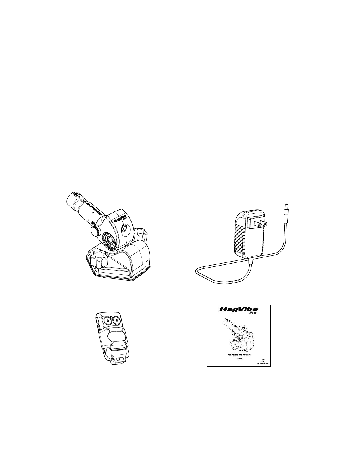
In the Box
Page 7

Warranty
New equipment sold by Superior Innovations is warranted to be free
from manufacturing defects under normal service for a period of one (1)
year from date of purchase by the original consumer. Component
manufacturers offer separate warranties and are covered separately.
These components are the lithium polymer battery, the electric motor,
RF remote control batteries (27A) and the battery indicator. These
components carry a 180-day warranty from the original date of
purchase. For complete information or to request a return goods
authorization number (RGA#) call technical service at (844) 624-8423.
Superior Innovation’s obligation under this warranty is expressly limited
to the replacement or repair at our service facility or one that has been
pre-authorized by Superior Innovations.
This warranty does not apply to defects caused by damage,
unreasonable use, faulty repairs made by others or defects caused by
failure to provide reasonable maintenance, while in the possession of the
consumer. Further, the warranty is void if the product, or any of its
components, is altered or modified by the consumer or if the product is
used in an inappropriate manner not recommended by the
manufacturer.
Page 8
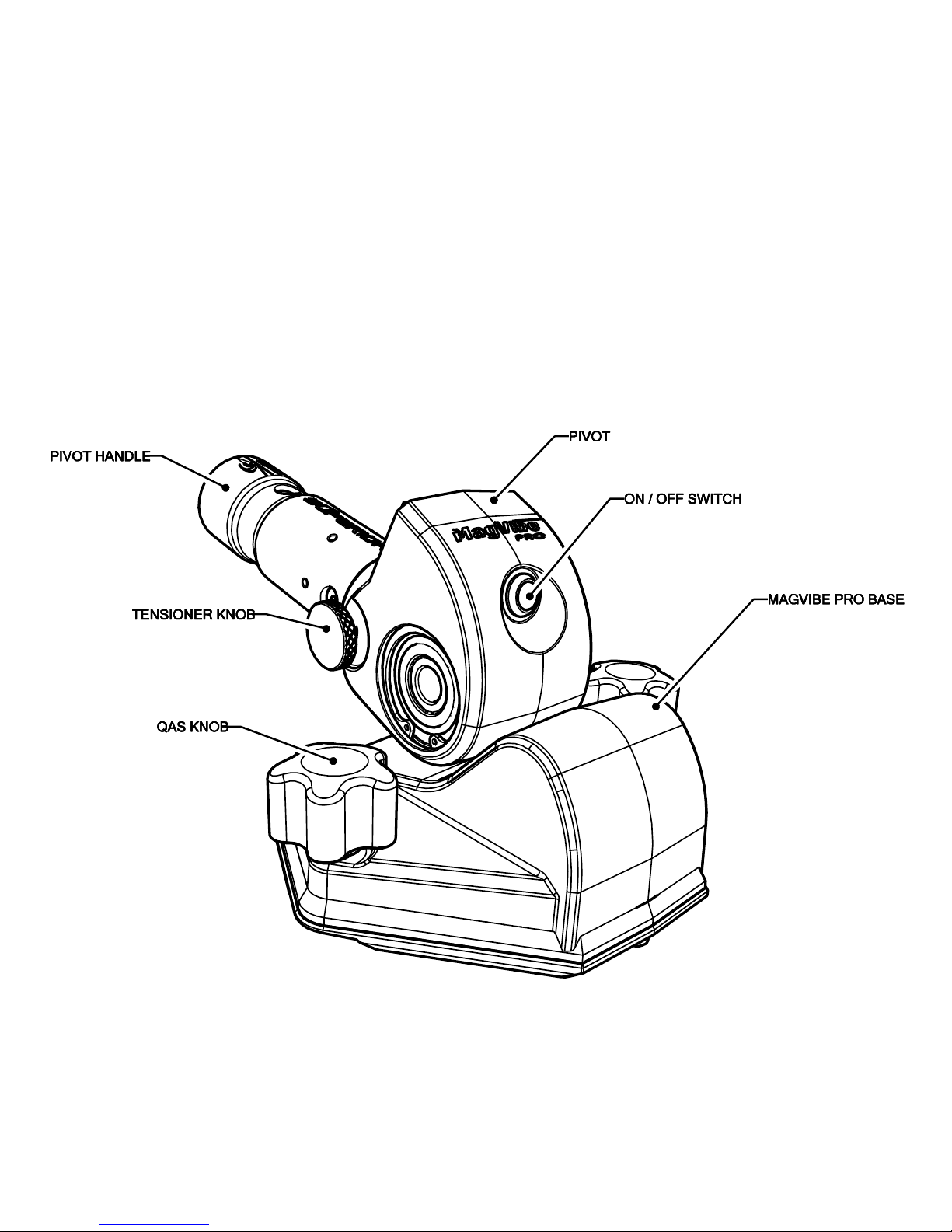
Description / Features / Controls
Page 9
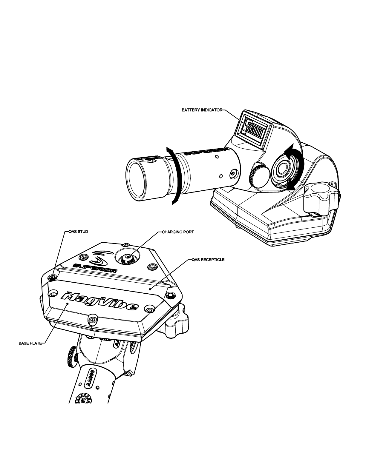
Description / Features / Controls
Rotating the pivot handle will
pivot the MagVibe Pro base.
From stop to stop is 50°.
Page 10

QAS™ is a quick attach system designed to make it quick and easy to attach a Magvibe™
Pro, ProTilt©, or accessories to a ProFloat© or other manufacturers floats. The ability to
quickly Remove the pivot allows for stacking of floats for transportation, easier cleanup
and the ability to switch floats very fast. The Magvibe™ Pro, ProTilt© and ProFloat© have
a built-in QAS™ mounts. For other types of floats there are a variety of QAS™ adapters:
The QAS™-M is a four bolt adapter, the QAS™-W is a t-washer adapter for channel mount
floats. There is also a QAS™-F adapter that converts a standard pivot to have a quick
attach system so you can attach to a ProFloat©.
QAS™-M Adapter
QAS™-F Adapter
QAS™-W Adapter
Page 11
ProFloat© Attachment
Loosen both QAS™ knobs by turning them
counter-clockwise.
Make sure that the threaded
studs are retracted enough to
clear the QAS™ dovetail.
Page 12

Align the QAS™
receptacle with the
QAS™ dovetail and
slide over to engage.
Center the
MagVibe Pro™
over the QAS™
dovetail and
tighten both QAS™
knobs by turning
them clockwise.
Page 13

Four Fastener Float Attachment (QAS™-M)
Place QAS™-M adapter
onto four fastener
float and tighten (4)
3/8”-16 x ½” Low head
socket head cap
screws (supplied with
adapter). You will
need a 3/16” Allen tool
for this operation.
Loosen both QAS™
knobs by turning
them
counterclockwise.
Make sure that the
threaded studs are
retracted enough to
clear the dovetail.
Page 14

Align and slide the dovetail
over the QAS™ receptacle
located on the bottom of
the Magvibe™, Protilt© or
accessory.
Tighten both
QAS™ knobs
by turning
them
clockwise.
Page 15

QAS™-W
Slide (2) QAS™-W T-washers into the channel of the float. Place the dovetail mount onto
the float and tighten (4) M6 x 10mm socket head cap screws (supplied with adapter).
You will need a 4mm Allen tool for this operation.
Page 16

Loosen both QAS™ knobs
by turning them
counterclockwise. Make
sure that the threaded
studs are retracted
enough to clear the
dovetail.
Align and slide the
Magvibe™ Pro QAS™
receptacle over the
dovetail on the QAS™W adapter.
Tighten both
QAS™ knobs by
turning them
clockwise.
Page 17

Attaching the Pole Extension
Press and hold the pins in pole extension, then align and insert into Magvibe™ Pro pivot
handle. Push into bore and make sure that the pins snap through the two holes in the
pivot handle to engage.
Same procedure for an
outside pole extension; except you will
slide the pole extension over the pivot handle. The
Magvibe™ Pro pivot handle will accommodate Ø1-3/8”
internal and Ø1-3/4” external poles.
Page 18

Turning Magvibe™ Pro On / Off
There are two ways to turn the Magvibe™ Pro on and off. The first method is to use the
pre-programmed RF remote control (supplied) and the second is to depress the latching
on / off switch.
To use the RF remote control, slide the protective button
cover downward to expose the buttons. There are two
buttons: Button A turns the Magvibe™ Pro on and off,
and Button B is an auxiliary RF control for powered
accessories from Superior Innovations.
To turn the Magvibe™ Pro on, simply press
button A and the vibration will start. When you
want to turn it off, press button A again. The
range will depend on surroundings, however, it
should have a forty-foot line of sight range.
Page 19

If you lose your RF remote control you can
still turn the Magvibe™ Pro on and off by
pressing the latching on / off switch.
NOTE: This switch is very compact and was
designed to be used as a failsafe if the RF
remote was lost.
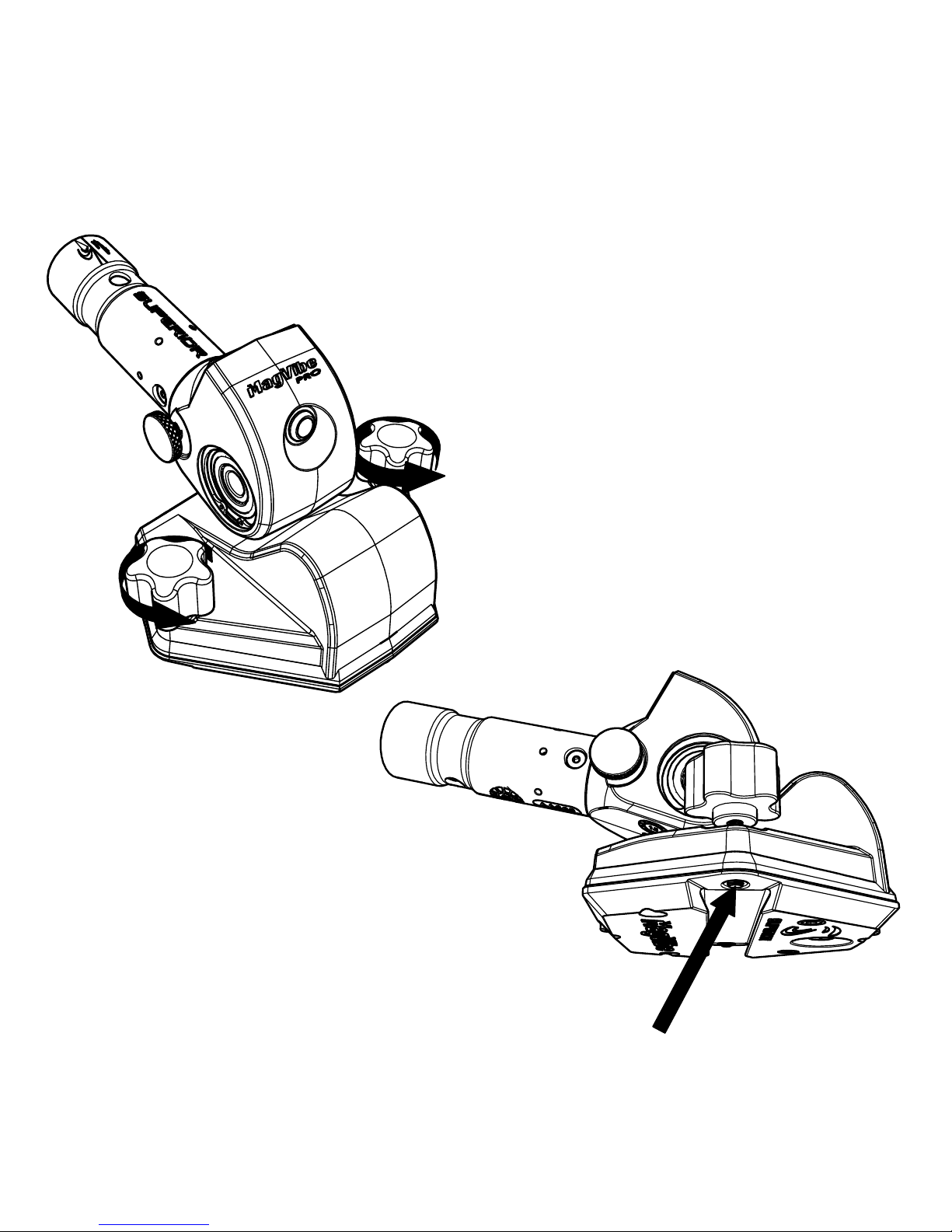
Adjusting the Pivot Tensioner
The pivot tension can be adjusted by the
user to add pressure to the gear-set which
creates friction to help hold the float at an
angle. The end result is a fatigue
reduction in the operator’s wrist and
hands.
To adjust; turn the
tensioner knob
clockwise. The
more it is turned
the more friction
is applied to the
gear-set. When
you want less of
an aid, turn the
tensioner knob
counterclockwise
to reduce friction.
Page 20

Battery Indicator
The battery indicator is positioned so the
operator can see the status of the battery when
the Magvibe™ Pro is in operation. There are 10
LED’s: 5 Green, 3 Amber and 2 Red. Every LED
represents approximately 10% of battery life.
For instance, if 6 LED’S are lit, you have
approximately 60% of battery life remaining.
Charging the Battery
The 18VDC Lithium
Polymer battery is built in
to the Magvibe™ Pro. It
has 3000mAh capacity
which should yield ~18hrs
on a single charge. To
charge it, plug the charger
(supplied) into a 120 VAC
wall outlet, and the 5mm
charging plug into the
charging port of the
Magvibe™ Pro. The
charging port is located
underneath the QAS™ base plate and must be removed from the float to charge.
Page 21
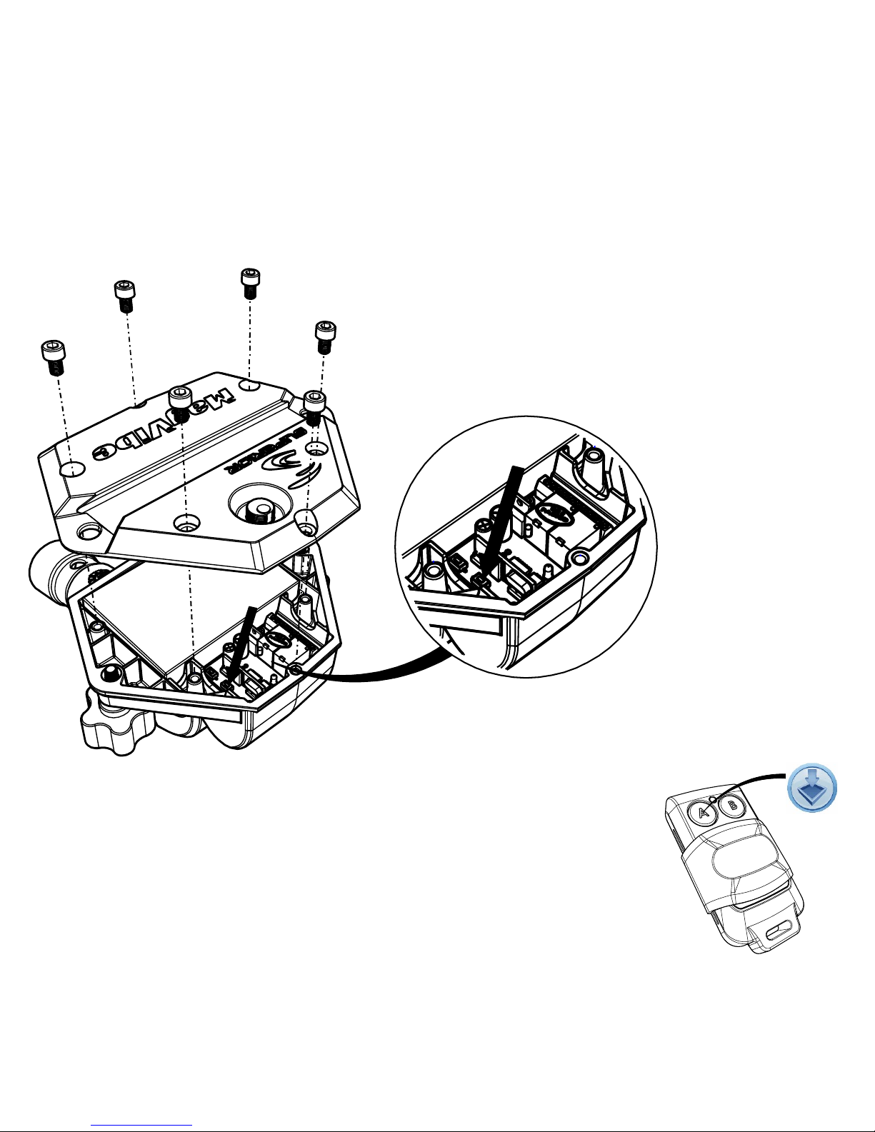
Programming a Replacement Remote
If you lost your remote and need to program a replacement, you can do it yourself. You
will need to order part number D-13535. Once you receive your replacement
remote, use a 4mm Allen key to remove (6) M5 socket
head cap screws on the bottom plate as shown. Lift
off the bottom plate to access the internal cavity of
the Magvibe™ Pro. The plate may resist a bit
due to the gasket sealer.
Once you are inside
of the cavity,
locate the RF /
Motor controller
board. The
button indicated
by the red arrow is
P1 and it will be used
for the programming of
channel 1. Press and hold P1 for at least
1 second; the LED on the board will light for 1 second, go
off for 1 second, and then light again.
Press and hold the A button on the remote control. If the code is
successfully received; the LED will blink, and you can release the A
button. If the code is unsuccessful; the LED will light for 10
seconds as it finishes the learning cycle.
Page 22

Once programming is successful, apply silicon sealer between the Magvibe™ Pro main
body and baseplate. Then reassemble in reverse order.
Maintenance Statement
The owner is responsible for the performance of all required maintenance, as described
in the Operator’s Manual.
Maintenance Schedule
Daily Maintenance
Weekly Maintenance
Monthly Maintenance
Cleaning (external)
Cleaning (external)
Cleaning (external)
Inspection
Inspection
Inspection
loose fasteners,
cracks, leaks, or other
obvious damage
loose fasteners,
cracks, leaks, or other
obvious damage
loose fasteners,
cracks, leaks, or other
obvious damage
Grease gears (see
maintenance in
Operator’s Manual)
Page 23

Maintenance
Remove MagVibe™ Pro from the float and clean after every use. Make sure to pay
special attention to the QAS™ receptacle. If concrete sets-up around the QAS™ it may
become difficult to use. The MagVibe™ Pro has sensitive electronics located inside the
pivot and the main body; DO NOT USE A PRESSURE WASHER.
Tip: Before use apply spray lubricant to the MagVibe™ Pro except to the battery
indicator and the on/off switch. This will make it much easier to clean up after use.
Once a month add
grease to the gears by
injecting it into the
pivot joint as shown.
Page 24

RF Remote Battery Replacement
To replace the battery in the RF remote controller remove
(4) screws on the back side of the RF remote control cover
using a Philips screwdriver.
Remove the RF remote back cover plate.
Make note of the battery polarity.
Remove the RF controller
board.
Remove the 27A battery.
MAKE SURE THAT THE
POLARITY IS CORRECT.
Install a new 27A
battery.
Reinstall the RF controller
board.
Place the RF remote back cover plate making
sure to align the screw holes.
Reinstall the (4) screws and tighten using a Philips
screwdriver. You may need to reprogram
MagVibe Pro RF receiver if the code was lost
during the battery reinstall process. See Programming
a Lost Remote in this manual for instructions.
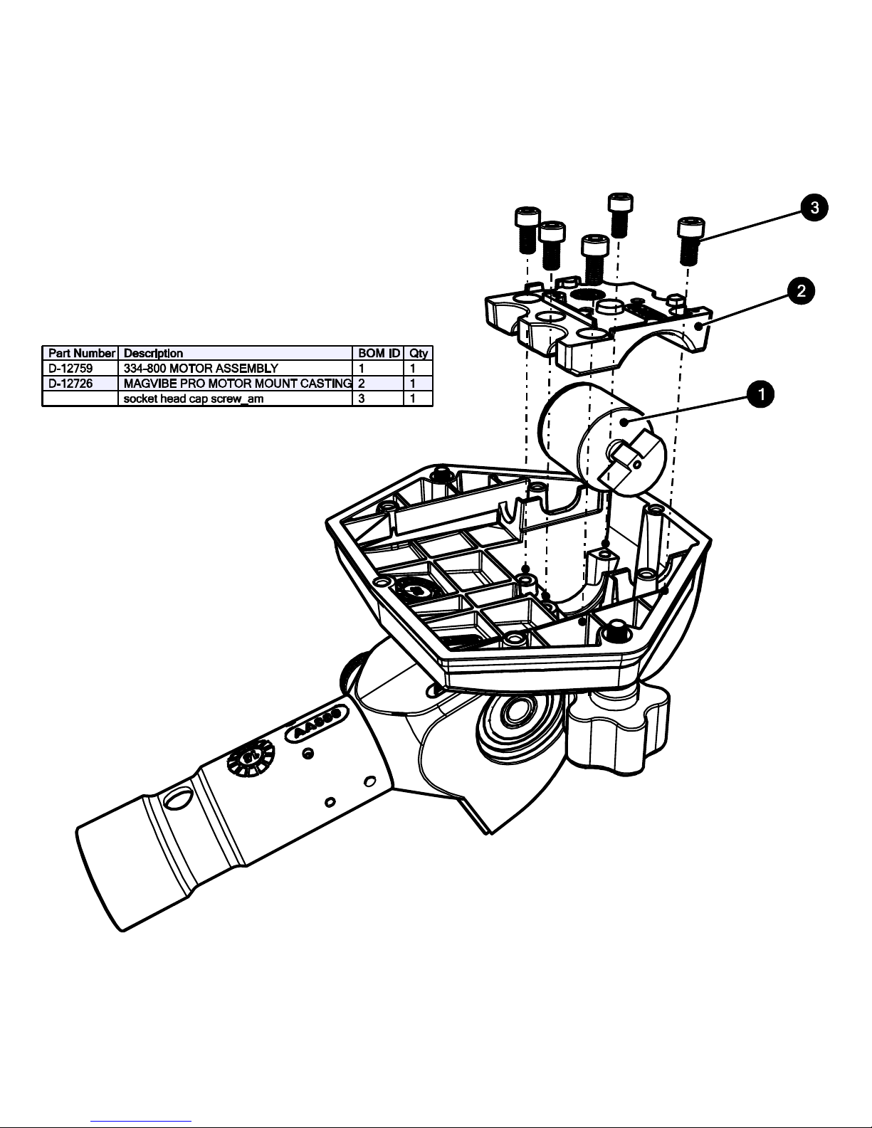
Page 25

Technical Data
Motor
24V DC, 0.6A
Battery
18V DC, 3000mAh Lithium
Polymer
Weight
Gears
Beveled, 3.17:1 ratio
Dimensional (L x W x H)
10.425” x 6.5” x 3.16”
(264.8mm x 165.1mm x
80.3mm)
Page 26

Page 27

Page 28

Page 29

Page 30
 Loading...