

Superior DS-36RN, DS-36RP, DSR-HTK, ELB-45, DSR-EXT12 Installation And Operating Instructions Manual
...
Installation
And Operating
Instructions
For Superior's
Discovety Series
Sealed Combustion
WARNING: IMPROPER
INSTALLATION
ADJUSTMENT,
ALTERATION,
SERVICI
OR
MAINTENANCE
CAN
CAUSE
INJURY
OR
PROPERTY
DAMAGE. REFER
TO
THIS
MANUAL.
FOR
ASSISTANCE
OR
AODI.
TIONALINFORMATION
CONSULTAIIUALI-
FIE0
INSTALLER,
SERVICE
AGENCY
OR
THE
GAS
SUPPLIER.
FOR YOUR
SAFETY
Natural Gas Models
DS-36RN
Propane Models
DS-36RP
Decorative Gas
Appliance
And Termination
Components
DSR-EXT12
DSR-EXT6
DSR-HTK
EL
B-45
What to do if you smell gas:
11-
Do not try to light any appliance.
I
Do not touch any electrical
switches. Do not use any phone in
your building.
Immediately call your gas supplier from a neighbor's phone.
Follow the gas supplier's instruc-
tions.
If you cannot reach your gas sup-
plier, call the fire department.
Do notstoreoruse gasoline
orother
flammable vapors or liquids in the
vicinity of this or any other appliance.
PLACES
ARE
VENTED
DECORATIVE
GAS
APPLIANCES.
DO
NOT
BURN
WOOD
OR
Due to high temperatures, the appliance should be located out of
traffic and away from furniture or
drapes. Do not place clothing or
other materials on or near the appliance.
I
PLEASE
RETAIN
THlS MANUAL
FOR
FUTURE
REFERENCE.
I
f i r e - p a r t s . c o m
I
TABLE
0,F
CONTENTS
-
......................................
lntroduct~on page
2
.........................
General information page 2
Location and clearances
..................
page
3
Installation
.....................................
a
3
Framing dimensions
........................
page 3
......................
Appliance dimensions page
5
..................
Outside wall termination page 6
Gas connections
...........................
-...page
8
....................
High elevation derating page
8
....................
Finishing requirements page 10
......................................
Accessories page
11
...........................
Operation and care page 11
Maintenance age 11
Partslcomponents
..........................
page 12
Troubleshooting guide
.....................
page 13
Replacement parts list
.....................
page 14
.......................
Liahtino instructions paqe 16
. .
Warranty.
-I
I
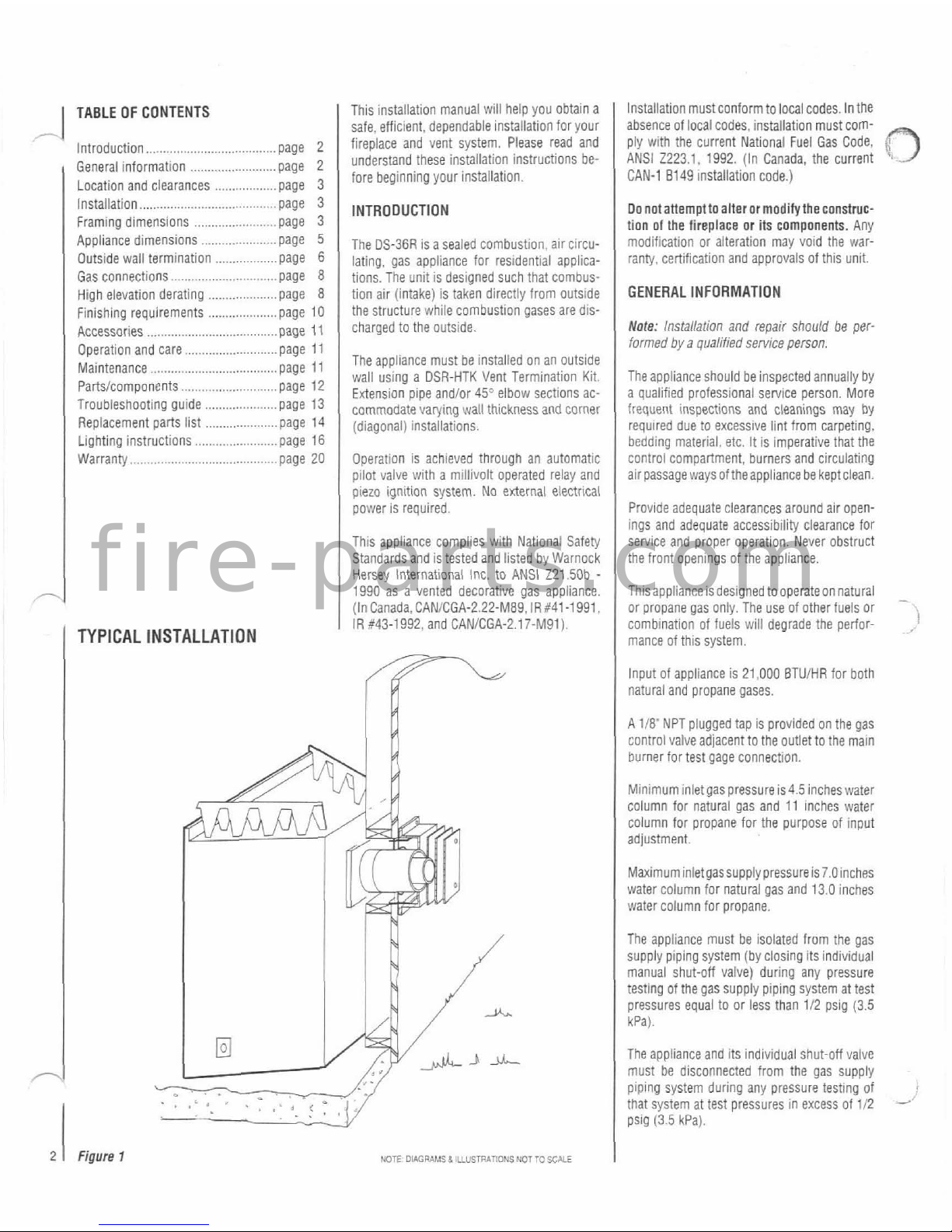
TYPICAL
INSTALLATION
This installation manual will help you obtain a
safe,
efficient,
dependable installation for your
fireplace and vent system. Please read and
understand these installation instructions before beginning your installation.
INTRODUCTION
The DS-36R is a sealed combustion,
alr circu-
lating, gas appliance for residential applica-
tions. The unit is designed such that combus-
tion air (intake) is taken directly from outside
the structure while combustion gases are discharged to the outside.
The appliance must be installed on an
outslde
wall using a DSR-HTK Vent Termination Kit.
Extension pipe
andlor 45Vlbow sections ac-
commodate varying wall thickness
and
corner
1
(diagonal) installations.
Operation is achieved through an automatic
pilot valve with a millivolt operated relay and
piezo ignition system. No external electrical
power is required.
This appliance complies with National Safety
Standards and is tested and listed by Warnock
Hersey International
lnc. to ANSI
Z21.50b
-
1990 as a vented decorative gas appliance.
(In
Canada,CAN/CGA-2.22-M89.lR:41-1991
IR 643-1992, and CANICGA-2.17-M91).
2
1
Figure
1
NOTE DiAcRAMs 8 UusrnArIoUs UoT
To
SCALE
Installation must conform to local codes. In the
absence of local codes, installation must comply with the current National Fuel Gas Code,
3
ANSI 2223.1. 1992. (In Canada, the current
CAN-1
8149 installation code.)
Donotanempttoalterormoditytheconstmc-
tion of the fireplace or its components. Any
modification or aiteration may void the warranty, certification and approvals of this unit.
GENERAL INFORMATION
Note:
Installation
and repair should be
per-
formed
by a qualified sennce person.
The appiiance should be inspected annually by
a oualified orofessionai service oerson. More
frequent
lnipections and cleanings may
by
required due to excessive lint from carpeting,
bedding
material. etc.
It
is imperative that the
control compartment, burners and circulating
air passage ways
oftheappllance be keptclean.
Provide adequate clearances around air openings and adequate accessibility clearance for
service and proper operation. Never obstruct
the front openings of the appliance.
Thlsappliance 1s deslgned tooperateon natural
-
or propane gas only The use of other fuels or
comb~nat~on of fuels
will
degrade the perfor-
.
mance of thls system
Input of appliance is 21,000
BTUiHR for both
natural and propane gases.
A 118' NPT plugged tap is provided on the gas
control valveadjacent to the outlet to the main
burner for test gage connection.
Mtn~mum inlet gas pressure is4.5 incheswater
column for natural gas and 11
Inches water
column for propane for the purpose of input
adjustment.
Maximum inletgassupply pressure
is7.Oinches
water column for natural gas and 13.0 inches
water column for propane.
The appliance must be isolated from the gas
supply
plping system (by closing its individual
manual shut-off valve) during any pressure
testing of the gas supply
piplng system at test
pressures equal to or less than 112 psig (3.5
kPa).
The appliance and its individual shut-off vaive
must be disconnected from the gas supply
piping system during any pressure testing of
that system at test pressures in excess of 112
-'
psig
(3.5
kPa).
f i r e - p a r t s . c o m
Do not use this appliance if any part has been
-
under water, Immediately call a qualified service technician to inspect the appliance and to
replace any pans of the control system that
have been under water.
ASSEMBLY STEPS
The typical sequence of installation foilows.
however,each installation isunique resultingin
variations to those described.
This appliance must be vented through an
1.
Construct appliance framing
outside wall and must not be connected to a
If the appliance is to be elevated above floor
level, a soiid continuous platform must be
constructed.
chimney or flue
sewing a soiid fuel burning
appliance.
LOCATION AND CLEARANCES
The header may rest on the top metal spacers.
but must not be notched to fit around them.
2.
Routegas supply line toappliance location.
3.
Position appliance and install the vent termination.
On
flatwall installations. two (2) studs (on
16'
centers. as illustrated) should be provided at
the rear structure to accommodate installation
of the vent termination.
In selecting the location, the esthetic and
func-
4.
Make connection
gas Supply and install
FRAMING DIMENSIONS
tional uses of the aonliance are orimaw con-
the log and burner assembly.
,
.
,
~~
cerns. However, thevent location and access to
the fuel supply are also important. Consideration should be given to
traffic ways, furniture.
draperies, etc., due to elevated surface temperatures. The location should also be free of
electrical or plumbing lines. Building codes
limit vent location in specific areas. Generally,
a Vent may not be located above. or within
6'
(1.8 m) of a gas regulator. Refer to
FigureGfor
exterior vent location limitations. Check local
codes for requirements.
Minimum clearances lo combustibles are:
,-
Appliance sides and back - 0"
floor - 0"
adjacent wall - 0'
celiing - 37-112'
(95
3
cm)
Vent
top
-
3'
(76
mm)
sides
-
1-314"
(44
mm)
bottom
-
1'
(25
mm)
The vent must have a minimum
Of3"Clearance
to any overhead combustible projection of
2-112" or less. Maintain
12'
clearance from
projections exceeding the
2-112" (Reference
Figure 2
)
.
+-.
Figure
2
5.
Install theoperating controlswitchand bring
in electrical service line for forced air circulating fan (optional equipment).
6.
install giass panel assembly.
7.
Finish enclosure walls and trim.
8.
Anachairlouversandioroptionaltrimpieces.
INSTALLATION
The appliance is shlpped with the controis and
burner tray instailed and pre-wired. Remove
the shipping carton. exposing the front glass
panel. Loosen and remove two (2) screws. with
springs,atthe
upperieftandrighthandcorners
of the glass frame, tiit outward. then lilt to
removethe glass panel.
Setthe panel asideand
protectfrom inadvertentdamage. Retainscrews.
springs and washers for
reassembly. Next.
remove the
carton(s) packed inside the appii-
ance and also set these aside.
Step
1.
Frame appliance enclosure as illus-
trated in
Figures 3 through
5,
Note: The frameddeprh (21-3i8"froma framed
wall) mustalways be measured from a finished
surface. If a wall covering such as
drywall is to
be
attached to the rear wall, then the 21-3/8~
must be measured from the drywall surface. It
is important that this dimension be exact in
order far the vent
term~nal kit to be connected
properly.
Similarly. the 34-71.?
(491
framing
dimension is important forcorner
ventconnec-
t10ns.
The appliance should be mounted on a fully
supported base extending the full width and
depth
ofthe unit. Theappliance may be located
on or nearconventional construction materials.
However, if installed on combustible materials,
Such as carpeting, vinyl tile, etc.. a metal or
wood barrier covering the entire bottom sur-
face
must
be
used.
15.
O.C.
l%.,i?
m*
+
Outside
Wall
Figure
3
Figure
4
I
NOTE
OWGRAMSb
ILIU5TR*mONS
WTTO
SCALE
I
Figure
5
f i r e - p a r t s . c o m
EXTERIOR VENT CLEARANCE REQUIREMENTS
a=
Air
Supply Inlet
Cl=
Vent
Terminal
A
r
Area
W)ma
Tminal Is
Not
Pennmed
I
A = clearance above grade, veranda, porch, deck, or balcony
12 inches (30 cm) minimum
B
=
clearance to window or door that may be opened
U.S.
-
9 inches
(22.5
cm) minimum
Canada
-
12 inches
(30
cm) minimum
C
=
clearance to permanently closed window - recommended to
prevent condensation on window
U.S.
-
9
inches (22.5 cm) minimum
Canada
-
12
inches (30 cm) m!nlmum
D
=
vertical ciearance to soffit located above the terminal
verlaled sorl
18
rcnes 146
CT)
ntnlmm
~nvent ate0
SOY
'2
ncpes
(46 cn, T n
~1-n
F
=
clearance to outside comer
12 inches (30
cm) minimum
G
=
clearance to inside comer
U.S.
-
6
inches (15.2 cm) minimum
Canada
-
2 feet
(60
cm) minimum
H
=
not be installed above a metedregulator assembly or within
3 feet (90 cm) horizontally from the center line of the
regulator.
I
Note:
Check
local codes or regulations for variations.
I
=
clearance to service regulator vent outlet
U.S.
-
3
feet ( 90 cm) minimum
Canada
-
6
feet (1.8 m) minimum
J
=
clearance to air supply inlet to building or Vle combustion
air inlet to any other appliance.
non-mechanical inlet:
US
-
9
inches (22.5 cm) minimum
Canada - 12 inches ( 30 cm) minimum
mechanical air supply:
6
feet (1.8 m) minimum
L
=
clearance above paved sidewalk or paved driveway located
on public
propeq
7
feet (2.1 m) minimum
Note:
A
vent shall
not
terminate directly above a sidewalk
or paved dnveway which is located between two
(2)
single
tami/y dwellings andserves
both
dwellings.
M = clearance under veranda, parch, deck, or balcony where
fully open on a minimum of two (2) s~des beneath the floor
12 inches (30
cm) minimum
-1
Figure
6
NOE.
OIAGRkLISd
IUUSTUATIOIIS
NOTTO
SCALE
f i r e - p a r t s . c o m
-
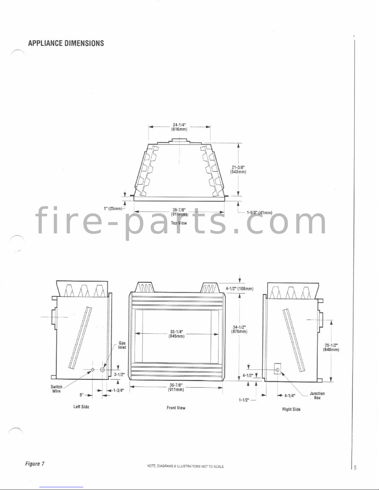
APPLIANCE DIMENSIONS
Too
View
,
4.1,4'
,--
Junction
1-l,Y
-
BOX
Len
Side
FmnI
View
Rlphl
Side
Figure
7
NOTE
OlAGRAMS
&
ILLUSBATIONS
NOTTO
SCALE
f i r e - p a r t s . c o m
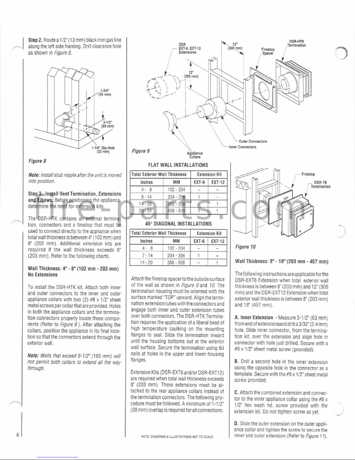
Step2. Routea112'(13mm) blackirongasline
-
along the leftsideframing. Driii clearance hole
as shown in
Figure
8.
MR
OSR-HTK
Termlnahon
-
UT4.
UT-12
Firertop
I
,'
Enensloor
r
Spacer
(32
mm)
Figure
8
Note:
Installstub nipple affer the unit is moved
into position.
Step3. Install Vent Termination, Extensions
and Elbows: Before positioning the appliance,
determine the need for extension kits.
The DSR-HTK contains an external termination, connectors and a
firestop that must be
-sed to clnnec: a~recrly :o 1-15 applarc? Nhen
I
lural wall thlcrtness s oerween @ 102
nrr,
ano
8'
(203 mm). Additional extension kits are
required if the wall thickness exceeds
8"
(203 mm). Refer to the following charts.
Walt Thickness:
4'-
8'
(102
mm
-
203
mm)
No Extensions
To install the DSR-HTK kit, Attach both inner
and outer connectors to the inner and outer
appliance collars with two
(2)
#8
x
112'
sheet
metal screws per collarthatare provided. Holes
in both the appliance collars and the termination connectors properly
locate these compo-
nents (Refer to
Figure 9 ).
After attaching the
collars, position the appliance in its final loca-
tion so that the connectors extend through the
exterior wall.
Note:
Walls that exceed
6-I/.
(765
mm) will
not permit
both
collars to extend aN the way
through.
\\
Louts
ConMdor.
Figure
9
'+\
lmr
~onnecmn
A
pllance
!011am
FLAT WALL INSTALLATIONS
Total Exterior Wall Thickness Extension Kit
Inches
EXT-6
EXT-12
204
-
356
14-20
356-
508
-
20-24 508 - 610
45"
DIAGONAL INSTALLATIONS
1
Inches
1
MM
I
MT-fi
EXT-12
4
8
1
in?-7M
I
-
I
-
Attach thefirestopspacerto theoutsidesurface
of the wail as shown in
Figure
9
and 10 The
termination housing must
be
oriented with the
surfacemarked "TOP" upward. Align
thetermi-
nation
extensiontubeswiththeconnectorsand
engage both inner and outer extension tubes
over both connectors. The
DSR-HTKTermination requires the application of a liberal bead of
high temperature caulking on the mounting
flanges to seal. Slide the termination inward
until the housing bottoms out at the exterior
wall surface. Secure the termination using 6d
nails at holes in the upper and lower housing
flanges.
Extension Kits
(DSR-EXTGandlor DSR-EXT12)
are required when total wall thickness exceeds
8"
(203 mm). These extensions must be at-
Figure
10
Wall Thickness:
8"
-
18"
(203
mm
-
457
mm)
1
Thefoliowing
instructionsareapplicableforthe
DSR-EXT6 Extension when total exterior wall
tached to the rear appliance collars instead of
the termination connectors. The following procedure must befollowed. A minimumof
1-11?
(38 mm) overlap is requiredforall connections.
Ihll:klless s o:?Neen 8'(203 mm! ano
12'(305
mm an0 !he DSZ-EX72 Extels on wnen tnra
.
exterlorwall thlcknessis between 8"(203 mm)
and
18'
(457
mm).
A.
Inner Extension -Measure 2-112" (63 rnm)
from endof
extensionaanddriIia3/32"(2.4mm)
hole. Slide inner connector, from the termination kit, over the extension and align hole in
connector with hole just drilled. Secure with a
R8 x 112' sheet metal screw (provided).
B.
Drill a second hole in the inner extension
using the opposite hole in the connector as a
template. Secure with
the#8xtITsheet metal
screw provided.
C.
Attach the combined extensionand connec-
tor to the inner appliance collar using the
#8
x
112' hex wash hd. screw provided with the
extension kit. Do not tighten screw as yet.
*
D. Slide the outer extension on the outerappliance collar and tighten the screw to secure the
inner and outer extension (Referta
Figure
11).
f i r e - p a r t s . c o m
 Loading...