

Superior DRL4543TEN, DRL4543TEP Installation And Operation Instructions Manual
Installation and Operation Instructions
P126718-01
PFS
Superior
P/N 126718-01 Rev. A 1/2014. Models
®
USC
INSTALLER: Leave this manual with the appliance.
CONSUMER: Retain this manual for future reference.
A barrier designed to reduce the risk of burns
from the hot viewing glass is provided with this
appliance and shall be installed.
This appliance may be installed in an aftermarket permanently located, manufactured home (USA only) or mobile
home, where not prohibited by local codes. This appliance is only for use with the type of gas indicated on the
rating plate. This appliance is not convertible for use with other gases, unless a certified kit is used.
Installateur : Laissez cette notice avec l’appareil.
Consommateur : Conservez cette notice pour consultation ultérieure.
Une barrière conçue pour réduire le risque de brûlure
par le hublot chaude est fournie avec l’appareil et doit
être installé.
TM
Direct-Vent Linear Gas Fireplace
DRL4543TEN DRL4543TEP
WARNING AVERTISSEMENT AVISO
HOT GLASS WILL
CAUSE BURNS.
UNE SURFACE VITRÉE CHAUDE PEUT
CAUSER DES BRÛLURES.
EL VIDRIO CALIENTE
CAUSARÁ QUEMADURAS.
DO NOT TOUCH GLASS
UNTIL COOLED.
NEVER ALLOW CHILDREN
TO TOUCH GLASS.
WARNING: If the information in these
instructions is not followed exactly, a fire or
explosion may result causing property damage,
personal injury or death.
— Do not store or use gasoline or other
flammable vapors and liquids in the vicinity
of this or any other appliance.
— WHAT TO DO IF YOU SMELL GAS:
• Do not try to light any appliance.
• Do not touch any electrical switch; do not
use any phone in your building.
• Immediately call your gas supplier from
a neighbor’s phone. Follow the gas
supplier’s instructions.
• If you cannot reach your gas supplier, call
the fire department.
— Installation and service must be performed
by a qualified installer, service agency or the
gas supplier.
LAISSER REFROIDIR LA SURFACE VITRÉE
NE PERMETTEZ JAMAIS À UN ENFANT DE
TOUCHER LA SURFACE VITRÉE.
USTED DEBE NUNCA TOCAR
AVANT D’Y TOUCHER.
AVERTISSEMENT : Assurez-vous de bien suivre les
instructions données dans cette notice pour réduire au
minimum le risque d’incindie ou d’explosion ou pour éviter
tout dommage matériel, toute blessure ou la mort.
— Ne pas entreposer ni utilizer d’essence ni d’autres
vapeurs ou liquides inflammables dans le voisinage
de cet appareil ou de tout autre appareil.
— QUE FAIRE SI VOUS SENTEZ UNE ODEUR DE GAZ :
• Ne pas tenter d’allumer d’appareil.
• Ne touchez à aucan interrupteur. Ne pas vous
servir des téléphones se trouvant dans le bâtiment
où vous trouvez.
• Appelez immédiatement votre fournisseur de
gaz depuis un voisin. Suivez les instructions du
fournisseur.
• Si vous ne pouvez rejoindre le fournisseur de gaz,
appelez le service des incindies.
— L’installation et l’entretien doivent être assurés par un
installateur ou un service d’entretien qualifié ou par le
fournisseur de gaz.
EL VIDRIO CALIENTE.
LOS NIÑOS DEBEN NUNCA
TOCAR EL VIDRIO.

TABLE OF CONTENTS
Safety .................................................................. 2
Local Codes......................................................... 4
Product Identication ........................................... 5
Product Features ................................................. 5
Requirements for the Commonwealth of
Massachusetts..................................................... 6
Pre-installation ..................................................... 7
Location of Termination Cap .............................. 10
Venting Installation .............................................11
Fireplace Installation.......................................... 19
Operation ........................................................... 26
Inspecting Burners............................................. 28
Cleaning and Maintenance ................................ 28
SAFETY
Replacing Light Bulbs ........................................ 29
Gas Control Module System.............................. 30
Remote Control Operation................................. 30
Specications .................................................... 33
Replacement Parts ............................................ 33
Technical Service............................................... 33
Service Hints ..................................................... 33
Wiring Diagram .................................................. 34
Troubleshooting ................................................. 35
Parts .................................................................. 38
Accessories ....................................................... 41
Warranty ............................................................ 42
WARNING: Improper installation, adjustment, alteration,
service or maintenance can
cause injury or property damage.
Refer to this manual for correct
installation and operational
procedures. For assistance or
additional information consult
a qualified installer, service
agency or the gas supplier.
This appliance is only for use
with the type of gas indicated on
the rating plate. This appliance
is not convertible for use with
other gases, unless a certied
kit is used.
State of Massachusetts: The
installation must be made by a
licensed plumber or gas tter
in the Commonwealth of Massachusetts.
WARNING: This product
contains and/or generates
chemicals known to the State
of California to cause cancer or
birth defects or other reproductive harm.
IMPORTANT: Read this owner’s
manual carefully and completely
before trying to assemble, op-
erate or service this replace.
Improper use of this replace
can cause serious injury or
death from burns, re, explosion, electrical shock and carbon
monoxide poisoning.
DANGER: Carbon monoxide
poisoning may lead to death!
WARNING: Do not slam or
strike glass doors. Damage can
result in a hazardous condition.
Young children should be carefully supervised when they are in the same
room as the appliance. Toddlers, young children and others may be
susceptible to accidental burns.A physical barrier is recommended if there
are at-risk individuals in the house. To restrict access to a replace or
stove, install an adjustable safety gate to keep toddlers, young children and
other at-risk individuals out of the room and away from hot surfaces.
www.SuperiorFireplaces.US.com
126718-01A2
SAFETY
Continued
This vented gas replace is a sealed combustion gas replace designed for residential applications. This replace must be installed with
INNOVATIVE HEARTH PRODUCTS vent pipe
components and terminations.
This fireplace complies with the National
Safety Standards and is listed and tested by
the PFS Corporation to ANSI Z21.50/CSA 2.22
standard as vented gas replace and applicable sections of Z21.97 standard for outdoor
decorative gas appliance (When installed as a
see-thru unit using outdoor kit model LDSTO).
NOTICE: Decorative product not
for use as a heating appliance.
This replace must be installed by a qualied
(certied or licensed) service person. It brings
in fresh air for combustion through the outer
pipe and combustion gases are exhausted
through the inner pipe. If the glass door assembly and venting pipe are not properly seated,
connected and sealed, carbon monoxide leakage (spillage) can occur.
Carbon Monoxide Poisoning: Early signs of
carbon monoxide poisoning resemble the u,
with headaches, dizziness or nausea. If you
have these signs, the replace may not be
working properly. Get fresh air at once! Have
replace serviced. Some people are more affected by carbon monoxide than others. These
include pregnant women, people with heart
or lung disease or anemia, those under the
inuence of alcohol and those at high altitudes.
Natural and Propane/LP Gas: Natural and
propane/LP gas are odorless. An odor-making
agent is added to the gas. The odor helps you
detect a gas leak. However, the odor added to
the gas can fade. Gas may be present even
though no odor exists.
Make certain you read and understand all
warnings. Keep this manual for reference. It
is your guide to safe and proper operation of
this replace.
WARNING: Any change to
this replace or its controls can
be dangerous. Do not modify
this replace under any circumstances. Any parts removed for
servicing must be replaced prior
to operating replace.
WARNING: Do not use a
blower insert, heat exchanger
insert or other accessory not ap-
proved for use with this replace.
WARNING: This appliance
is only for use with the type of
gas indicated on the rating plate.
This appliance is not convertible
for use with other gases unless
a certied kit is used.
WARNING: Do not allow fans
to blow directly into the replace.
Avoid any drafts that alter burner
ame patterns.
Due to high temperatures, the
appliance should be located out
of trafc and away from furniture
and draperies.
Do not place clothing or other
ammable material on or near
the appliance. Never place any
objects on the appliance.
Do not use this replace to cook
food or burn paper or other am-
mable material.
This replace reaches high temperatures. Keep children and
adults away from hot surface
to avoid burns or clothing ignition. Fireplace will remain hot
for a time after shutdown. Allow
surface to cool before touching.
Carefully supervise young children when they are in the room
with replace.
126718-01A 3
www.SuperiorFireplaces.US.com
SAFETY
Continued
Keep the area around your
replace clear of combustible
materials, gasoline and other
ammable vapor or liquids. Do
not run replace where these
are used or stored.
1. For propane/LP replace, do not place
propane/LP supply tank(s) inside any
structure. Locate propane/LP supply
tank(s) outdoors. To prevent performance
problems, do not use propane/LP fuel tank
of less than 100 lb. capacity.
2. If you smell gas
• shut off gas supply
• do not try to light any appliance
• do not touch any electrical switch; do not
use any phone in your building
• immediately call your gas supplier from
a neighbor’s phone. Follow the gas supplier's instructions
• if you cannot reach your gas supplier,
call the re department.
3. Never install the replace
• in a recreational vehicle
• in windy or drafty areas where curtains or
other combustible (ammable) objects can
make contact with the replace front
• in high trafc areas
4. Turn fireplace off and let cool before
servicing, installing or repairing. Only a
qualied service person should install,
service or repair this replace. Have replace inspected annually by a qualied
service person.
5. You must keep control compartments,
burners and circulating air passages
clean. More frequent cleaning may be
needed due to excessive lint and dust
from carpeting, bedding material, etc.
Turn off the gas valve and pilot light before
cleaning replace.
6. Have venting system inspected annually
by a qualied service person. If needed,
have venting system cleaned or repaired.
See Cleaning and Maintenance, page 28.
7. Do not use any solid fuels (wood, coal,
paper, cardboard, etc.) in this replace.
Use only the gas type indicated on re-
place nameplate.
8. This appliance, when installed, must be
electrically grounded in accordance with
local codes or, in the absence of local
codes, with the National Electrical Code,
ANSI/NFPA 70 or Canadian Electrical
Code, CSA C22.1.
9. Do not use replace if any part has been
exposed to or under water. Immediately
call a qualied service person to arrange
for replacement of the unit.
10. Do not operate replace with glass door
removed, cracked or broken.
11. Provide adequate clearances around air
openings.
LOCAL CODES
Install and use replace with care. Follow all
local codes. In the absence to local codes,
use the current National Fuel Gas Code ANSI
Z223.1/NFPA 54* (USA) or the current CSAB149.1 Installation Code (Canada).
*Available from:
American National Standards Institute, Inc.
1430 Broadway
New York, NY 10018
National Fire Protection Association, Inc.
Batterymarch Park
Quincy, MA 02269
www.SuperiorFireplaces.US.com
126718-01A4
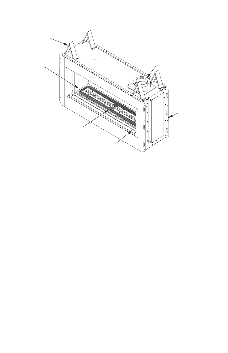
Top
Spacers
PRODUCT IDENTIFICATION
Glass Door
Pebble Pan
Access Door
Figure 1 - Direct Vent Linear Fireplace
PRODUCT FEATURES
These are a few facts that can help you un-
derstand and enjoy your direct vent replace:
• The venting system may be routed to the
outside of your home in several ways. It
may vent through the roof (vertical) or it
may vent to an outside/exterior wall (horizontal). The vent pipe installation is very
important to allow for proper operation.
You must follow the venting instructions
very carefully for either vertical or horizontal
applications.
• This replace may be installed in any room
of your house provided all local codes and
these installation instructions are followed.
Flue Collar
Nailing
Flange
• Each time you turn on your replace, you
may notice some amount of condensation
on the inside of the replace glass. This
is normal and will disappear after 10-20
minutes of operation.
• Your direct vent gas fireplace system
(replace and venting) is a balanced and
sealed gas operating unit. It requires approximately 10-20 minutes of operating
time before the ame pattern stabilizes.
126718-01A 5
www.SuperiorFireplaces.US.com

REQUIREMENTS FOR THE COMMONWEALTH OF
MASSACHUSETTS
For all side wall horizontally vented gas fueled
equipment installed in every dwelling, building or
structure used in whole or in part for residential
purposes, including those owned or operated by
the Commonwealth and where the side wall exhaust vent termination is less than seven (7) feet
above nished grade in the area of the venting,
including but not limited to decks and porches,
the following requirements shall be satised:
INSTALLATION OF CARBON
MONOXIDE DETECTORS
At the time of installation of the side wall horizontal vented gas fueled equipment, the installing
plumber or gastter shall observe that a hard
wired carbon monoxide detector with an alarm
and battery backup is installed on the oor level
where the gas equipment is to be installed. In
addition, the installing plumber or gastter shall
observe that a battery operated or hard wired carbon monoxide detector with an alarm is installed
on each additional level of the dwelling, building or
structure served by the side wall horizontal vented
gas fueled equipment. It shall be the responsibility
of the property owner to secure the services of
qualied licensed professionals for the installation
of hard wired carbon monoxide detectors.
In the event that the side wall horizontally
vented gas fueled equipment is installed
in a crawl space or an attic, the hard wired
carbon monoxide detector with alarm and
battery back-up may be installed on the next
adjacent oor level.
In the event that the requirements of this
subdivision can not be met at the time of
completion of installation, the owner shall
have a period of thirty (30) days to comply with
the above requirements; provided, however,
that during said thirty (30) day period, a battery
operated carbon monoxide detector with an
alarm shall be installed.
Approved Carbon Monoxide Detectors
Each carbon monoxide detector as required
in accordance with the above provisions shall
comply with NFPA 720 and be ANSI/UL 2034
listed and IAS certied.
SIGNAGE
A metal or plastic identication plate shall be
permanently mounted to the exterior of the
building at a minimum height of eight (8) feet
above grade directly in line with the exhaust
vent terminal for the horizontally vented gas
fueled heating appliance or equipment. The
sign shall read, in print size no less than 1/2" in
size, "GAS VENT DIRECTLY BELOW. KEEP
CLEAR OF ALL OBSTRUCTIONS".
www.SuperiorFireplaces.US.com
INSPECTION
The state or local gas inspector of the side
wall horizontally vented gas fueled equipment
shall not approve the installation unless, upon
inspection, the inspector observes carbon
monoxide detectors and signage installed in
accordance with the provisions of 248 CMR
5.08(2)(a) 1 through 4.
EXEMPTIONS: The following equipment is
exempt from 248 CMR 5.08(2)(a) 1 through 4:
• The equipment listed in Chapter 10 entitled
"Equipment Not Required To Be Vented"
in the most current edition of NFPA 54 as
adopted by the Board; and
• Product Approved side wall horizontally
vented gas fueled equipment installed in a
room or structure separate from the dwelling, building or structure used in whole or
in part for residential purposes.
MANUFACTURER REQUIREMENTS
Gas Equipment Venting System Provided
When the manufacturer of Product Approved
side wall horizontally vented gas equipment
provides a venting system design or venting
system components with the equipment, the
instructions provided by the manufacturer for
installation of the equipment and the venting
system shall include:
• Detailed instructions for the installation of
the venting system design or the venting
system components; and
• A complete parts list for the venting system
design or venting system.
Gas Equipment Venting System Not
Provided
When the manufacturer of a Product Approved side wall horizontally vented gas fueled equipment does not provide the parts for
venting the ue gases, but identies "special
venting systems", the following requirements
shall be satised by the manufacturer:
•
The referenced "special venting system" instructions shall be included with the appliance
or equipment installation instructions; and
• The "special venting systems" shall be Prod-
uct Approved by the Board, and the instructions for that system shall include a parts list
and detailed installation instructions.
A copy of all installation instructions for all
Product Approved side wall horizontally
vented gas fueled equipment, all venting instructions, all parts lists for venting instructions, and/or all venting design instructions
shall remain with the appliance or equipment
at the completion of the installation.
126718-01A6

PRE-INSTALLATION
LOCATION AND SPACE
REQUIREMENTS
Determine the safest and most efcient location for your direct vent replace. Make sure
that rafters and wall studs are not in the way
of the venting system. Choose a location
where the heat output is not affected by drafts,
air conditioning ducts, windows or doors.
Be aware of all restrictions and precautions
before deciding the exact location for your
replace and termination cap.
When deciding the location of your replace,
follow these rules:
• Do not connect this replace venting to a
chimney ue serving a separate solid-fuel
burning replace or appliance.
• Due to high temperatures, do not locate this
replace in high trafc areas, windy or drafty
areas or near furniture or draperies.
• Proper clearances must be maintained.
• If your replace is to be installed directly on
carpeting, vinyl tile or any combustible material other than wood, it must be installed on a
metal or wood panel extending the full width
and depth of the replace (see Figure 6).
• If standoff spacers are attached to your
replace, these spacers can be placed
directly against wall or framing material.
See framing details, page 8.
• When locating termination cap, it is important to observe the minimum clearances
shown in Figure 7, page 10.
• Do not recess termination cap into a wall
or siding.
• You may paint the termination cap with
450º F (232º C) heat-resistant paint to
coordinate with the exterior nish.
• There must not be any obstruction such as
bushes, garden sheds, fences, decks or
utility buildings within 24" from the front of
the termination cap and the front of outside
air vent.
• Do not locate termination cap and outside
air vent where excessive snow or ice build
up may occur. Be sure to clear vent termination area after snow falls to prevent
accidental blockage of venting system.
When using snow blowers, do not direct
snow towards vent termination area.
CLEARANCES
Minimum clearances to combustibles for the
replace are as follows:
*Back and sides 1"
Perpendicular walls 8"
Floor (From bottom of Fireplace) 0"
Ceiling (From bottom of Fireplace) 63"
Top of Enclosure
(From bottom of Fireplace) 63"
Top of Standoffs 0"
Vent 1"
(See venting instructions for specic venting
clearances.)
* For back and sides of replace, do not pack
with insulation or other materials.
NOTICE: This replace is intended for use as supplemental heat.
Use this replace along with
your primary heating system.
Do not install this replace as
your primary heat source. If you
have a central heating system,
you may run system’s circulat-
ing blower while using replace.
This will help circulate the heat
throughout the house.
FRAMING AND FINISHING
Figure 2, page 8 shows typical framing of this
replace. Figure 3, page 8 shows framing for
see-thru installation. All minimum clearances
must be met. Vent pipe needs to maintain 1"
clearance. Steel framing may be necessary or
wood studs may be notched. Concrete board
is provided for facing around the replace as
shown in Figure 4, page 8.
If you are using a separate combustible man-
tel piece, refer to Figure 5 page 8 for proper
installation height. You can install noncombus-
tible mantels at any height above the replace.
Note: Noncombustible mantels may discolor!
126718-01A 7
www.SuperiorFireplaces.US.com
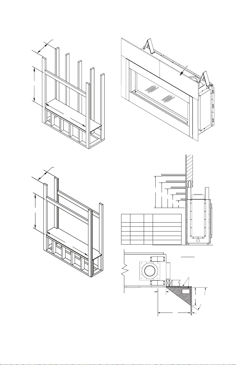
17.50"
53.25"
38"
15.25"
PRE-INSTALLATION
38"
53.25"
Figure 2 - Framing Clearances for One
Sided Application
38"
15.25"
53.25"
Continued
Ref.
1 12" A 24"
2 9" B 21"
3 6" C 18"
4 4" D 16"
5 2" E 14"
Concrete
Board
Figure 4 - Installing Concrete Board
Wall
1
2
3
4
C
5
D
E
TOP VIEW
Mantel
Depth Ref.
A
B
Mantel from
Top of Opening
Figure 3 - Framing Clearances for See-
Thru Application
www.SuperiorFireplaces.US.com
Combustible
Material May
Be Used
4" to Face Opening
SAFE
ZONE
5"
33°
8"
Perpendicular
Wall
Figure 5 - Clearances for Combustible
Mantels
126718-01A8
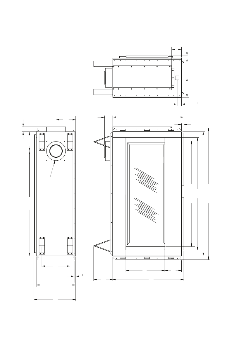
55 1/16"
PRE-INSTALLATION
Continued
4 1/8"
1"
8 1/4"
1 13/16"
2 1/32"
43 7/8" 8 1/8"
8 1/4"
8" DIA. OUTER
5" DIA. INNER
11 13/16"
16 1/2"
5/8"
8 1/4"
3 13/32"
29 13/16"
16 9/32"
29 25/32"
7 1/32"
1"
47"
44 1/16"
52"
17 1/2"
Figure 6 - Direct Linear Fireplace Series Dimensions
126718-01A 9
www.SuperiorFireplaces.US.com
Fixed
Closed
Openable
Fixed
Closed
V
V
V
V
V
V
V
V
X
X
V
X
G
G
J
F
B
B
K
N
H
I
A
N
E
L
D
B
M
A
C
B
V
V
A
G
G
B
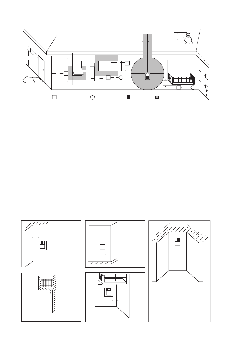
TERMINATION CAP
AIR SUPPLY INLET
GAS METERRESTRICTED AREA
(TERMINATION PROHIBITED)
A = clearance above grade, veranda, porch, deck, or
balcony [*12" (30.5 cm) minimum]
B = clearance to window or door that may be opened
[6" (15 cm) min. for 10,000 Btu or less; 9" (23 cm) in US
if between 10,000 and 50,000, 12" (30 cm) in Canada
if between 10,000 and 100,000; 12" (30 cm) in US if
greater than 50,000, 36" (91 cm) in Canada if greater
than 100,000]
C = clearance to permanently closed window
[minimum 12" (30.5 cm) recommended to prevent
condensation on window]
D = vertical clearance to ventilated soffit located above the
terminal within a horizontal distance of 24" (61 cm) from
the center-line of the terminal [18" (45.7 cm) minimum]
E = clearance to unventilated soffit [12" (30.5 cm) minimum]
F = clearance to outside corner (see below)
G = clearance to inside corner (see below)
H = *not to be installed above a meter/regulator assembly
within 36" (91.4 cm) horizontally from the center line
of the regulator
I = clearance to service regulator vent outlet [*72" (182.9 cm)
minimum]
J = clearance to non-mechanical air supply inlet to building
or the combustion air inlet to any other fireplace
[6" (15 cm) min. for 10,000 Btu or less; 9" (23 cm) in US
if between 10,000 and 50,000, 12" (30 cm) in Canada
if between 10,000 and 100,000; 12" (30 cm) in US if
greater than 50,000, 36" (91 cm) in Canada if greater
than 100,000]
K = clearance to a mechanical air supply inlet [*In Canada,
6 ft. (1.83m) minimum; In US 3 ft. (91 cm) above if within
10 ft. (3 m) horizontally]
L = † clearance above paved side-walk or a paved driveway
located on public property [*84" (213.3 cm) minimum]
M = clearance under veranda, porch, deck
[*12" (30.5 cm) minimum ‡]
N = clearance above a roof shall extend a minimum of
24" (61 cm) above the highest point when it passes
through the roof surface and any other obstruction within
a horizontal distance of 18" (45.7 cm)
† vent shall not terminate directly above a side-walk or paved driveway which is located between two
single family dwellings and serves both dwellings*
‡ only permitted if veranda, porch, deck or balconey is fully open on a minimum of 2 sides beneath the floor*
* as specified in CAN/CSA B149 (.1 or .2) Installation Codes (1991) for Canada and U.S.A.
Note: Local codes or regulations may require different clearances
A = 6" (15.2 cm)
Inside Corner
V
B
E
V
B = 6" (15.2 cm)
C = Maximum depth of 48" (121.9 cm)
for recessed location
D = Minimum width for back wall of
recessed location Combustible - 38" (965 mm)
Noncombustible - 24" (61 cm)
E = Clearance from corner in
recessed location Combustible - 6" (15.2 cm)
Noncombustible - 2" (5.1 cm)
Outside Corner Recessed Location
G
H
G = 12" (30.5 cm) minimum clearance
Balcony with No Side Wall
V
J
Combustible &
Noncombustible
H = 24" (61 cm)
J = 20" (50.8 cm)
Balcony with Perpendicular Side Wall
C
D
C
Termination Clearances for Buildings with Combustible and Noncombustible Exteriors
Openable
LOCATION OF TERMINATION CAP
Figure 7 - Minimum Clearances for Termination Cap
www.SuperiorFireplaces.US.com
126718-01A10
VENTING INSTALLATION
NOTICE: Read these instructions completely before attempting installation.
These models are tested and approved for
use with an IHP (direct vent) pipe components
and terminations.
The venting system must terminate on the
outside of the structure and can not be at-
tached to a chimney or ue system serving a
separate solid fuel or gas burning appliance.
A direct vent appliance must have its own
venting system. DO NOT common vent this
appliance.
These models are approved to be vented
either horizontally through an outside wall or
vertically through a roof or chase enclosure
using the following guidelines:
• When venting system terminates horizontally on an outside wall, you may install
a standoff if the termination cap is to be
installed directly on a combustible nish
such as vinyl, wood, stucco, etc.
• Never run the vent downward as this may
cause excessive temperatures which could
cause a re.
• Vent pipe air space clearances to com-
bustibles are 1" on all sides except on the
horizontal sections, which requires 2" clearance from the top of the pipe. Where the
termination cap penetrates a combustible
wall, 1" air space clearance is required.
• Have replace and selected vent components on hand to help determine the exact
measurements when elbowing or offsetting.
Always use wall restops when penetrating
walls and restops when penetrating ceil-
ings or attic spaces.
• For installation of replace at elevations of
4000 feet or greater, pay special attention
to venting requirement recommendations.
WARNING: Read all instructions completely and thoroughly
before attempting installation.
Failure to do so could result in
serious injury, property damage
or loss of life.
NOTICE: Do not seal termination
cap to vent pipe. Cap must be
removable for vent inspection
and maintenance.
INSTALLATION PRECAUTIONS
• Wear gloves and safety glasses for
protection
• Use extreme caution when using ladders
or when on roof tops
• Be aware of electrical wiring locations in
walls and ceilings
The following actions will void the warranty
on your venting system:
• Installation of any damaged venting
component
• Unauthorized modication of the venting
system (Do not cut or alter vent components)
• Installation of any component part not
manufactured or approved by INNOVATIVE
HEARTH PRODUCTS
• Installation other than as instructed by
these instructions
WARNING: This gas replace
and vent assembly must be
vented directly to the outside.
The venting system must NEVER
be attached to a chimney serving a separate solid fuel burning
appliance. Each direct vent gas
appliance must use a separate
vent system. Do not use common vent systems.
WARNING: Vent pipe air
space clearances to combus-
tibles are 1" on all sides except
on the horizontal sections,
which require 2" clearances
from the top of the pipe. Where
the termination cap penetrates
a combustible wall, 1" air space
clearance is required.
NOTICE: Failure to follow these
instructions will void the warranty.
126718-01A 11
www.SuperiorFireplaces.US.com
INSTALLATION PLANNING
(Framing
Detail)
11
1
/2"
11
1
/2" Inside Framing
11
1
/2"
8 1/2"
Vent Opening
Combustible Wall
Vent Opening
Noncombustible Wall
There are two basic types of direct vent
installation:
• Horizontal Termination
• Vertical Termination
Horizontal Termination Installation
IMPORTANT: Horizontal square terminations
require only inner portion of wall restop.
Horizontal installations using round termina-
tion require exterior portion of wall restop.
1. Set replace in its desired location and de-
termine the route your horizontal venting
will take. Do not secure replace until all
venting has been installed. Some instal-
lations require sliding replace in and out
of position to make nal venting connec-
tions. Figures 11 and 12 on page 13 show
different congurations for venting with
horizontal termination that will help you
decide which application best suits your
installation. Check to see if wall studs or
roof rafters are in the path of your desired
venting route. If they are, you may want
to adjust location of replace.
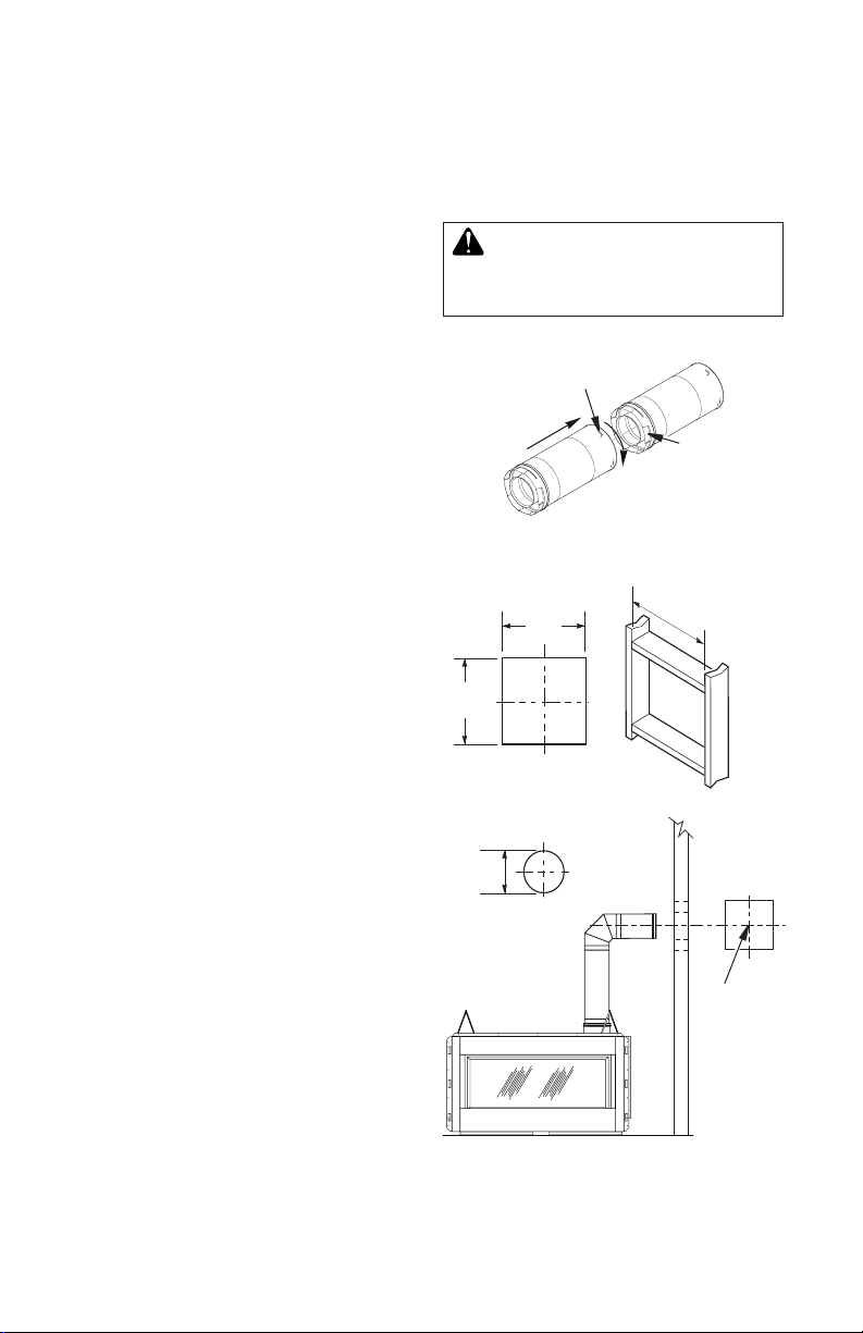
2. Direct vent pipe sections and components
are designed with special twist-lock connections.
Twist-Lock Procedure: Female ends of
pipes have locking lugs (indentations).
These lugs will slide straight into match-
ing slots on male ends of adjacent pipes.
Push pipe sections together and twist
one section clockwise approximately onequarter turn until sections are fully locked
(see Figure 8).
Note: Horizontal runs of vent must be sup-
ported every three feet. Use wall straps
for this purpose.
3. Assemble desired combination of pipe
and elbows to replace ue collar. If there
are long portions of venting run, preassembled pipe sections may be installed
as subassemblies for convenience.
4. Carefully determine location where vent
pipe assembly will penetrate outside wall.
Center of hole should line up with center
line of horizontal vent pipe. Mark wall for
an 11 1/2" x 11 1/2" square hole. Cut and
frame square hole in exterior wall where
vent will be terminated. If wall being pen-
VENTING INSTALLATION
Continued
etrated is constructed of noncombustible
material, such as masonry block or concrete, a 8 1/2" hole with zero clearance is
acceptable (see Figure 9).
WARNING: Do not recess
vent termination into any wall.
This will cause a re hazard.
Figure 8 - Vent Pipe Connections
Figure 9 - Vent Opening Requirements
www.SuperiorFireplaces.US.com
Female
Locking Lugs
Male
Slots
Center
of Hole
126718-01A12

VENTING INSTALLATION
Continued
5. Noncombustible Exterior Wall: Position
horizontal vent cap in center of the 8 1/2"
round hole and attach to exterior wall
with four wood screws provided. Before
attaching vent cap to exterior wall, run a
bead of non-hardening mastic (pliable
sealant) around outside edges to make a
seal between it and outside wall.
Note: Four wood screws provided should
be replaced with appropriate fasteners for
stucco, brick, concrete or other types of
sidings (see Figure 10).
Combustible Exterior Wall: For vinyl
siding, stucco or wood exteriors, a siding
standoff may be installed between vent
cap and exterior wall. Siding standoff
prevents excessive heat from damaging
siding materials. Siding material must be
cut to accommodate standoff. Bolt vent
cap to standoff. Apply non-hardening
mastic around outside edge of standoff.
Position standoff/cap assembly in the
center of 11 1/2" square hole and attach to
exterior wall with provided wood screws
(see Figure 11). Siding standoff must sit
ush against exterior fascia material.
6. Connecting Vent Cap with Horizontal
Vent Pipe: Slide wall restop over vent
pipe before connecting horizontal run to
vent cap (see Figure 12).
Apply
Mastic to All
Four Sides
Vent Cap
Wood
Screw
Carefully move replace, with vent as-
sembly attached, toward wall and insert
vent pipe into horizontal termination. Pipe
overlap should be a minimum of 1 1/4" (see
Figure 13, page 14).
Slide wall restop against interior wall
surface and attach with screws provided.
See Figure 13, page 14, for horizontal
termination details.
Place replace into position and shim with
noncombustible material if needed. Nail or
screw side anges to framing to secure
unit in place. IMPORTANT: Make sure re-
place is level before securing. If replace
is not level it will not work properly.
Cut Siding Away to
Fit Standoff
Standoff
Apply Mastic
to All Four Sides
Figure 11 - Installing Siding Standoff
(Combustible Exterior Wall)
Wood
Screw
Vent
Cap
Screws
Interior Wall
Surface
Wall
Firestop
Vent Cap
(Horizontal
Figure 10 - Installing Horizontal Vent Cap
(Noncombustible Exterior)
126718-01A 13
www.SuperiorFireplaces.US.com
Termination)
Screw
Figure 12 - Connecting Vent Cap with
Horizontal Vent Pipe
Horizontal
Vent Pipe
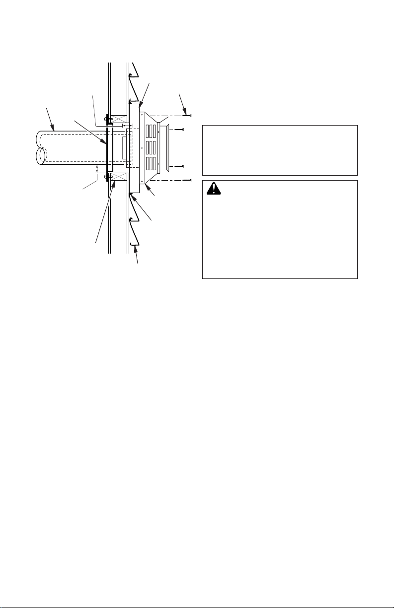
VENTING INSTALLATION
Minimum
Pipe
Direct
Vent
Pipe
Maintain 1"
Minimum Air
Space Around
Outer Pipe When
Penetrating a Wall
Overlap
4
11/
Wall
Firestop
11 1/2" x 11 1/2"
Framed Opening
Exterior Wall with Vinyl Siding
Figure 13 - Typical Horizontal
Termination Cap Mounting with
Additional Siding Standoff Installed
Siding
Standoff
High Wind
Termination
Continued
Screws
Apply
Mastic to
Outside
Edge of
Standoff
Horizontal Termination Congurations
Figure 14 and 15, page 15, shows the congurations for venting with horizontal termination
with a chart of critical minimum and maximum
dimensions which MUST be met.
NOTICE: Do not seal termination
cap to vent pipe. Cap must be
removable for vent inspection
and maintenance.
WARNING: Never run vent
downward as this may cause
excessive temperatures which
could cause a re. Operation of
improperly installed and maintained venting system could
result in serious injury, property
damage or loss of life.
www.SuperiorFireplaces.US.com
126718-01A14
 Loading...