

Super Hot SG-135-E, SG-495-E, MG-50-E, MG-150-E, SG135 Installation And Service Manual
...
r
INSTALLATION AND SERVICE MANUAL
INSTALLATION AND SERVICE MANUAL
SG SERIES BOILERS
WARNING
Improper installation, adjustment, alteration, service or maintenance can cause property
damage, injury, or loss of life
additional information, consult a qualified installer, service agency or the gas supplier.
SG SERIES BOILERS
FOR MODELS SG-135-E TO SG-495-E
FOR MODELS SG-135-E TO SG-495-E
SEE REAR COVER FOR INDEX
SEE REAR COVER FOR INDEX
Models SG-135-E to SG-270-E
. Please carefully read this manual. For assistance o
Manufacturers of Gas and Electric Boilers, Stainless Steel Tanks, Heat Exchangers and Electric Boosters.
Manufacturers of Gas and Electric Boilers, Stainless Steel Tanks, Heat Exchangers and Electric Boosters.
94 Riverside Drive, North Vancouver, B.C. V7H 2M6 • Telephone (604) 929-1214 • www.alliedboilers.com
94 Riverside Drive, North Vancouver, B.C. V7H 2M6 • Telephone (604) 929-1214 • www.alliedboilers.com
PN2362763
Manufactured by
Manufactured by
Allied Engineering Company
Allied Engineering Company
Division of E-Z-Rect Manufacturing Ltd.
Division of E-Z-Rect Manufacturing Ltd.
Branches: Calgary • Edmonton • Toronto • Denver
Branches: Calgary • Edmonton • Toronto • Denver
`
SG SERIES BOILERS
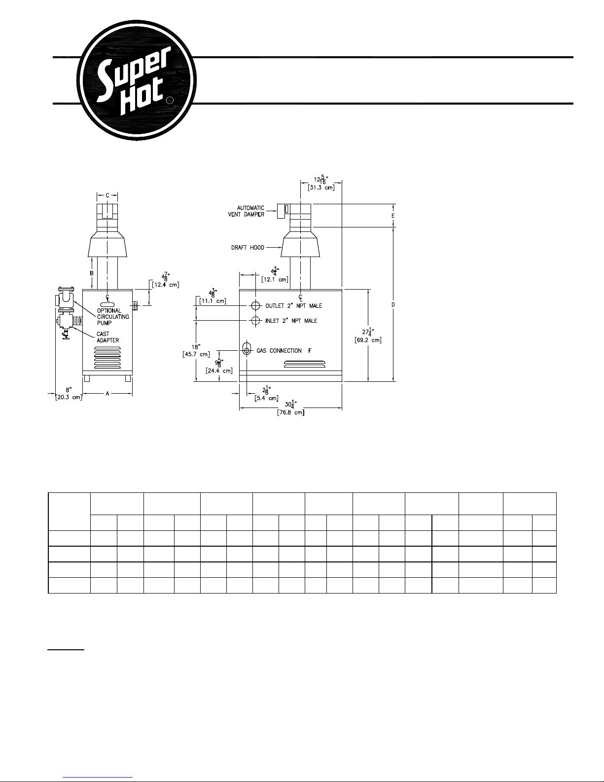
DIMENSIONS AND SPECIFICATIONS
FOR MODELS SG-135 TO SG-270
Standard Model Includes:
• Electronic Ignition
• Zone Control Board with Transformer
• Stainless Steel Burners
• Combination Gas Valve
• High Limit Sensor
• Temperature / Pressure Gauge
• A.S.M.E. Pressure Relief Valve
• Drain Valve
• Draft Hood
• Blocked Vent Safety Switch
• Flame Roll-out Safety Switch
• Automatic Vent Damper
“PS” Packaged Models Include
Standard Model Parts plus:
• Circulating Pump
• Custom Cast Iron Pump Adapter
• Expansion Tank
• Air Purger
• Combination Fill / Regulator Valve
• Automatic Air Vent
Allow 24” (609 mm) minimum in front for servicing.
Minimum clearances to combustible material: Top 24” (610 mm), Sides 2" (51 mm), Rear 2" (51 mm), Flue 6" (153 mm)
APPROVED FOR COMBUSTIBLE FLOORS & CLOSET INSTALLATION.
The Super Hot product improvement program may result in changes to the design and / or specifications being made without notice.
MODEL
NUMBER
SG135 135 39.6 114 33.4 14.7 37.3 9.5 24.1 6.0 15.2 45.3 115 4.5 13.9 0.50” 191 87
SG180 180 52.8 152 44.5 17.7 45.0 9.5 24.1 6.0 15.2 45.3 115 4.5 13.9 0.50” 222 101
SG225 225 65.9 190 55.6 20.7 52.6 9.5 24.1 7.0 17.8 46.5 118 6.5 16.5 0.75” 253 115
SG270 270 79.1 228 66.9 23.7 60.2 9.5 24.1 8.0 20.3 47.6 121 7.5 19.0 0.75” 284 129
* For altitudes above 2,000 feet, refer to Section 3.6 to determine the appropriate Input derate or contact the factory.
** Output based on Natural Gas models
INPUT* OUTPUT** DIM A DIM B DIM C DIM D DIM E
MBH kW MBH kW in cm in cm in cm in cm in cm NPT lb kg
GAS
CONN. F
SHIPPING
WEIGHT
Options:
• Natural Gas add suffix "N" - Propane models add suffix “P”
• Electric Ignition add suffix “E”
• High/Low fire add suffix “M” - Consult Factory for Availability
• Add 45 pounds weight (20 kg) for packaged boilers - add suffix “PS”
2

SG SERIES BOILERS
DIMENSIONS AND SPECIFICATIONS
FOR MODELS SG-315 TO SG-495
Standard Model Includes:
• Electronic Ignition
• Stainless Steel Burners
• Gas Valve
• Redundant Gas Valve
• Operating Aquastat
• High Limit Sensor
• Temperature / Pressure Gauge
• A.S.M.E. Pressure Relief Valve 30 p.s.i.
• Drain Valve
• Draft Hood
• Transformer
• Control Panel Enclosure
Allow 24” (610 mm) minimum in front for servicing.
Minimum clearances to combustible material: Top 24” (610 mm), Sides 2” (51 mm), Rear 2” (51 mm), Flue 6" (153 mm)
APPROVED FOR COMBUSTIBLE FLOORS & CLOSET INSTALLATION, do not install on carpeting.
The Super Hot product improvement program may result in changes to the design and / or specifications being made without notice.
MODEL
NUMBER
SG315 315 92.3 265 77.7 7.9 26.7 67.8 9.5 24.1 8.0 20.3 47.6 121 3/4” 307 140
SG360 360 106 303 88.8 9.0 29.7 75.4 9.5 24.1 9.0 22.9 48.6 124 3/4” 336 153
SG400 400 117 337 98.7 10.0 32.7 83.1 9.5 24.1 9.0 22.9 48.6 124 3/4” 368 167
SG450 450 132 379 111 11.3 35.7 90.7 15.5 39.4 10.0 25.4 55.3 140 1” 395 180
SG495 495 145 416 122 12.4 38.7 98.3 15.5 39.4 10.0 25.4 55.3 140 1” 424 193
INPUT* OUTPUT DIM A** DIM B DIM C DIM D
MBH kW MBH kW H.P. in Cm in cm in cm in cm
GAS
CONN. F
Typical
NPT
SHIPPING
WEIGHT
lb kg
* In Canada: For altitudes above 2,000 feet, contact the factory for the appropriate Input derate.
* In U.S.A.: For altitudes above 2,000 feet, reduce input 4% for each 1000 feet above sea level.
** Add 3” to dimension ‘A’ (1 1/2” to each side of boiler) to allow for 2” NPT water connections.
Options:
• Natural Gas add suffix "N" - Propane models add suffix “P”
• Electric Ignition add suffix “E”
• High/Low fire add suffix “M” - Full Modulation add suffix “MOD”
3
SG Series Boilers – Installation and Service Manual
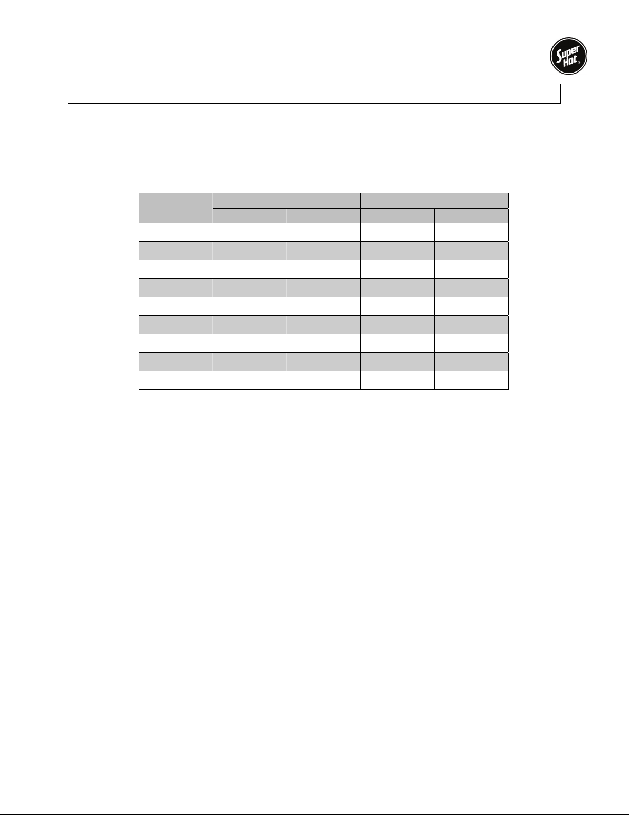
Boiler Water Flow Data
NOTE: The boiler should be properly sized for its heating application and maintain an adequate water
flow rate during operation. Significantly oversizing the boiler or decreasing boiler water flow
rate will cause excessive stage cycling and may result in premature failure of components.
Typical Water Flow Versus Pressure Drop Across Boiler
Model
Number
U.S. GPM P.D. FT. U.S. GPM P.D. FT.
SG135 11.4 2.8 7.6 1.2
SG180 15.1 2.8 10.1 1.2
SG225 18.9 2.8 12.6 1.2
SG270 22.7 2.8 15.1 1.2
SG315 26.5 3.2 17.7 1.3
SG360 30.3 3.2 20.2 1.4
SG400 33.6 3.3 22.4 1.4
20°F T.D. 30°F T.D.
SG450 37.8 3.8 25.2 1.6
SG495 41.6 4.0 27.7 1.8
4

SG Series Boilers – Installation and Service Manual
ABOUT OUR MANUALS
Your Super Hot boiler has been provided with two manuals:
• User's Information Manual - This manual is intended for the owner or user of the boiler and provides
information on routine operation and maintenance, and emergency shutdown.
• Installation and Service Manual - This manual must only be used by a qualified heating installer,
service technician or gas supplier. Installation or service by anyone unqualified to do so may
result in severe personal injury, death or substantial property damage.
Both manuals should be kept in the envelope provided and affixed adjacent to the boiler so that they are
readily available for future reference.
Lighting Instructions Section 1
1.1 SAFETY INSTRUCTIONS
WARNING
If you do not follow these instructions exactly, a fire or explosion may result causing property
damage, personal injury or loss of life.
A. BEFORE LIGHTING smell all around the
boiler area for gas. Be sure to smell next to
the floor because some gas is heavier than
air and will settle on the floor.
WHAT TO DO IF YOU SMELL GAS
• Do not try to light any appliance.
• Do not touch any electrical switch; do not
use any phone in your building.
• Immediately call your gas supplier from a
neighbor's phone. Follow the gas
supplier's instructions.
• If you cannot reach your gas supplier,
call the fire department.
B. Use only your hand to push in or turn the gas
C. Do not use this boiler if any part has been
control knob. Never use tools. If the knob will
not push in or turn by hand, don't try to repair
it, call a qualified service technician. Force or
attempted repair may result in a fire or
explosion.
under water. Immediately call a qualified
service technician to inspect the appliance
and to replace any part of the control system
and any gas control which has been under
water.
1.2 LIGHTING INSTRUCTIONS
Determine the ignition system that applies from the list below and go to the applicable lighting instruction
section.
• Intermittent electronic ignition with combination gas valve (Section 1.3)
• Intermittent electronic ignition with non-combination gas valve (Section 1.4)
Note: A combination gas valve combines the operating and safety shut-off into one valve body. A noncombination gas valve system utilizes separate valve bodies for operating and safety shut-off.
If you are unsure which type of gas valve or ignition system your boiler is equipped with, check the
lighting instructions sticker on the boiler or contact the factory.
5

SG Series Boilers – Installation and Service Manual
1.3 LIGHTING INSTRUCTIONS FOR INTERMITTENT ELECTRONIC IGNITION
WITH COMBINATION GAS VALVE.
1. This boiler is equipped with an ignition device
which automatically lights the pilot. Do not
to light the pilot by hand. Ensure gas supply
to the boiler is turned on.
2. STOP! Read the safety instructions in
Section 1.1.
3. Set the room thermostat to lowest setting.
4. Turn off all electrical power to the appliance.
5. Remove control access panel if necessary.
6. Push in gas control knob slightly and turn
clockwise
to "OFF".
try
NOTE: On some gas valves the knob cannot
7. Wait five (5) minutes to clear out any gas.
8. Turn gas control knob counterclockwise
9. Replace control access panel if necessary.
10. Turn on all electrical power to the boiler.
11. Set room thermostat to desired setting.
12. If the appliance will not operate, follow the
To turn off gas to boiler or emergency shut-off
Follow Section 1.5.
be turned to "OFF" or “ON” position unless
knob is pushed in slightly. Do not force.
Then smell for gas, including near the floor. If
you smell gas, STOP! Follow "A" in the safety
instructions in Section 1.1. If you don't smell
gas, go to the next step.
to "ON".
instructions "To Turn Off Gas To Boiler" in
Section 1.6 and call your service technician or
gas supplier.
1.4 LIGHTING INSTRUCTIONS FOR INTERMITTENT ELECTRONIC IGNITION
WITH NON-COMBINATION GAS VALVE.
This boiler is equipped with an ignition device, which automatically lights the pilot. Do not try to light the
pilot by hand. Before turning on the electrical power switch, be sure all gas supply lines are purged of air
and power supply to control is the correct voltage.
If the pilot or main burners are not lit or the control system is locked-out due to flame failure, close the
main and pilot gas shut-off valves and call your service technician or gas supplier. If you smell gas,
STOP! Follow “A” in the safety instructions in Section 1.1.
Check Control Operation
1. STOP! Read the safety instructions in
Section 1.1.
2. For 100% shut off check, close main and pilot
manual gas shut off valves, turn off all
electric power to the boiler and wait for five
minutes to clear out any gas.
3. Then smell for gas, including near the floor.
If you smell gas, STOP! Follow safety
instructions in Section 1.1. If you don’t smell
gas, go to the next step.
4. Set the thermostat above room temperature
and turn on all electric power to the boiler to
energize the electronic ignition and pilot
valve. After a few seconds, control system
should “lockout” and all functions are off.
5. To take the control system out of “lockout”
either press the reset button or interrupt
power to the boiler, depending on the boiler
controller. Some controllers will retry ignition
automatically after 5 minutes lockout.
Start System
1. Turn on the main and pilot manual gas shutoff valves.
2. Set thermostat above room temperature and
turn on all electrical power to the boiler.
3. Once the pilot flame is proven, the controller
opens the main burner gas valves. The pilot
flame will ignite the gas as it exits the main
burner ports.
4. Set thermostat to the desired setting to put
system back in service.
Relight Operation
Five minutes complete shut off period is required
before attempting to relight the boiler. To relight
the boiler, follow the Start System procedure
(above).
To turn off gas to boiler or emergency shutoff
Follow Section 1.5
6
SG Series Boilers – Installation and Service Manual
y
1.5 TO TURN OFF GAS TO THE BOILER OR EMERGENCY SHUT-OFF
WARNING
Should boiler overheat, or the gas supply fail to shut off, do not turn off or disconnect the
electrical supply to the circulating pump. Instead, shut off the gas supply at a location external
to the boiler.
1. Set the thermostat to the lowest setting.
2. Turn all electrical power to the boiler off.
3. Remove control access panel on the boiler if necessary.
4. For combination valve: Push in gas control knob slightly and turn clockwise
force it.
For non-combination valve: Close the main and pilot manual gas shut off valves. The valve is "OFF"
when handle is perpendicular to the direction of gas flow.
5. Replace control access panel if necessary.
to "OFF". Do not
1.6 CONTROLLER PROGRAMMING AND SERVICE CODES
2012 NRCan and DOE Compliance and Operation
Operation of this control may delay the burner operation while the residual heat is circulated
out of boiler.
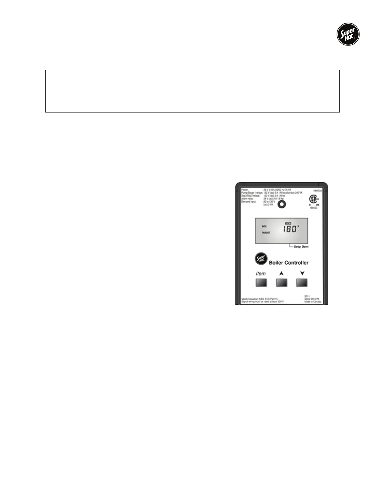
The integrated boiler control module provides ignition
sequence, flame monitoring and safety shutoff for intermittent
pilot spark ignition. It also provides limit rated water
temperature control for with two separate sensors in one
casing (3-wire).
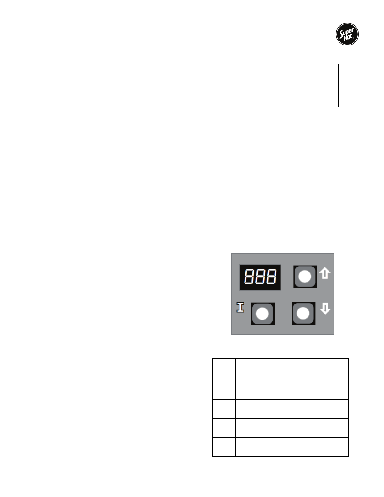
The control is located on the front panel inside the boiler.
The control display, along with Up ▲, Down ▼, and “I” keys
may be used to view boiler operating status and program
parameters (Figure 1).
1.6.1 RUN MODE
In the RUN mode, status items and parameters are
viewable.
To read settings, press and release the “I” key to find the
parameter of interest. Each setting will alternately flash
between the relevant display code listed in the Table 1
and its corresponding value. For example, press and
release “I” key until “HL_” setpoint is displayed, it will then
flash a three-digit number, i.e., 220, followed by ˚F (or ˚C).
This indicates that the boiler water temperature of 220 ˚F
is set. Other operating parameters display the settings in
a similar fashion.
7
Figure 1 Control Displa
Table 1 Run Mode Parameters
Text Description Display
STA Status (see status
numbers)
BT Boiler temperature
SP Operating setpoint
HL High limit setpoint
HDF Differential set-point
FLA Flame current
RUN Run time hours
CYC Boiler cycles
ERR Error (see error numbers)
StA
bt
SP
HL
HdF
FLA
run
CYC
Err

SG Series Boilers – Installation and Service Manual
p
1.6.2 INSTALLER MODE
To enter the adjustment mode:
1. Press with Up ▲, Down ▼, and “I” keys (see Figure 1) simultaneously for three seconds.
2. Press and release the “I” key until the parameter (listed in the Table 2) requiring adjustment is
displayed.
3. Press with Up ▲ or Down ▼ key until the parameter has reached the desired value.
4. After 60 seconds without any key inputs, the control will automatically return to the RUN Mode.
Table 2 Installer Mode O
3-Digit 7-Segment Display
1st Screen 2nd Screen (setting value) 3rd Screen
HL_
HdF
Or_
otH
otL
btL
tPL
tPt
rSt
F-C
<high limit> ˚F or ˚C 180 ˚F 130 to 220 ˚F Adjust high limit setting
<high limit differential> ˚F or ˚C 15 ˚F 10 to 30 ˚F
<pump overrun time> Sec 60 sec 0 to 120 seconds Pump post-purge time
<ODR maximal temp.> ˚F or ˚C 55 ˚F 40 to 70 ˚F
<ODR minimal temp.> ˚F or ˚C 0 ˚F -40 to 40 ˚F
<minimal water temp.> ˚F or ˚C 140 ˚F 130 to 150 ˚F
<minimal boiler temp.> ˚F or ˚C 140 ˚F
<maximal delay> Min 2 1 to 10 minutes
On or OFF N/A N/A Reset lockout
˚F or ˚C
tions
Default Range
˚F ˚F or ˚C
OFF,
120 to 160 ˚F
Description
Adjust high limit
differential
Maximal outdoor
temperature
Minimal outdoor
temperature
Minimal boiler
temperature
Thermal purging
minimal temperature
(parameter is available
only if outdoor
temperature is invalid)
Maximal thermal purge
time (parameter is
available only if outdoor
temperature is invalid)
Select degrees ˚F or ˚C
mode
8
SG Series Boilers – Installation and Service Manual
1.6.3 OPERATING CHECKOUT
After adjusting parameters, put the boiler into operation and observe operation through at least one
complete cycle to make sure that the controller operates properly. See controller troubleshooting section
to assist in determining boiler operation.
The sensor should fit snugly and should touch the bottom of the well for best temperature response. The
sensor is held inside the well using the well clip.
1.6.4 THERMAL PURGE
The intent of thermal purge is to ensure usable residual heat in the boiler is circulated until it is sufficiently
depleted from the system before the burner is allowed to fire. To that end, on a call for heat, the burner
remains off while the circulator runs until the boiler temperature drops to the thermal purge temperature
limit or the time delay is exceeded. Both of these parameters are adjustable. When the boiler temperature
falls below the thermal purge temperature limit or the time delay expires, the burner is allowed to fire.
In addition to the thermal purge temperature and thermal purge time delay parameters, two other
conditions release the integrated boiler controller from thermal purge and allow the burner to run in order
to maintain comfort in the space:
• The boiler temperature has dropped 10 °F from the boiler water temperature measured at the
beginning of the call for heat.
• Boiler temperature is cooling at a rate greater than 5 °F/minute while the circulator is running.
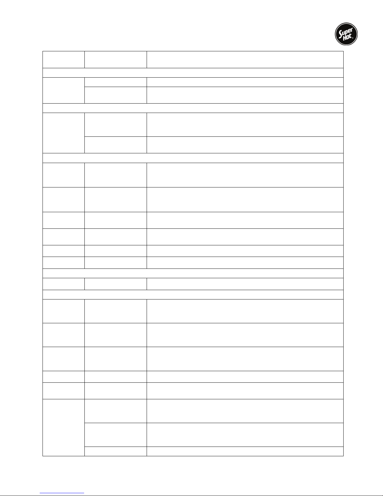
1.6.5 OPERATING STATE CODES AND TROUBLESHOOTING
When there is a problem during a call for heat or boiler operation, the controller provides specific
information to help resolve the issue quickly. If the controller is displaying “StA” by a number, use the
state code definitions in the Table 3 to determine the problem and possible causes.
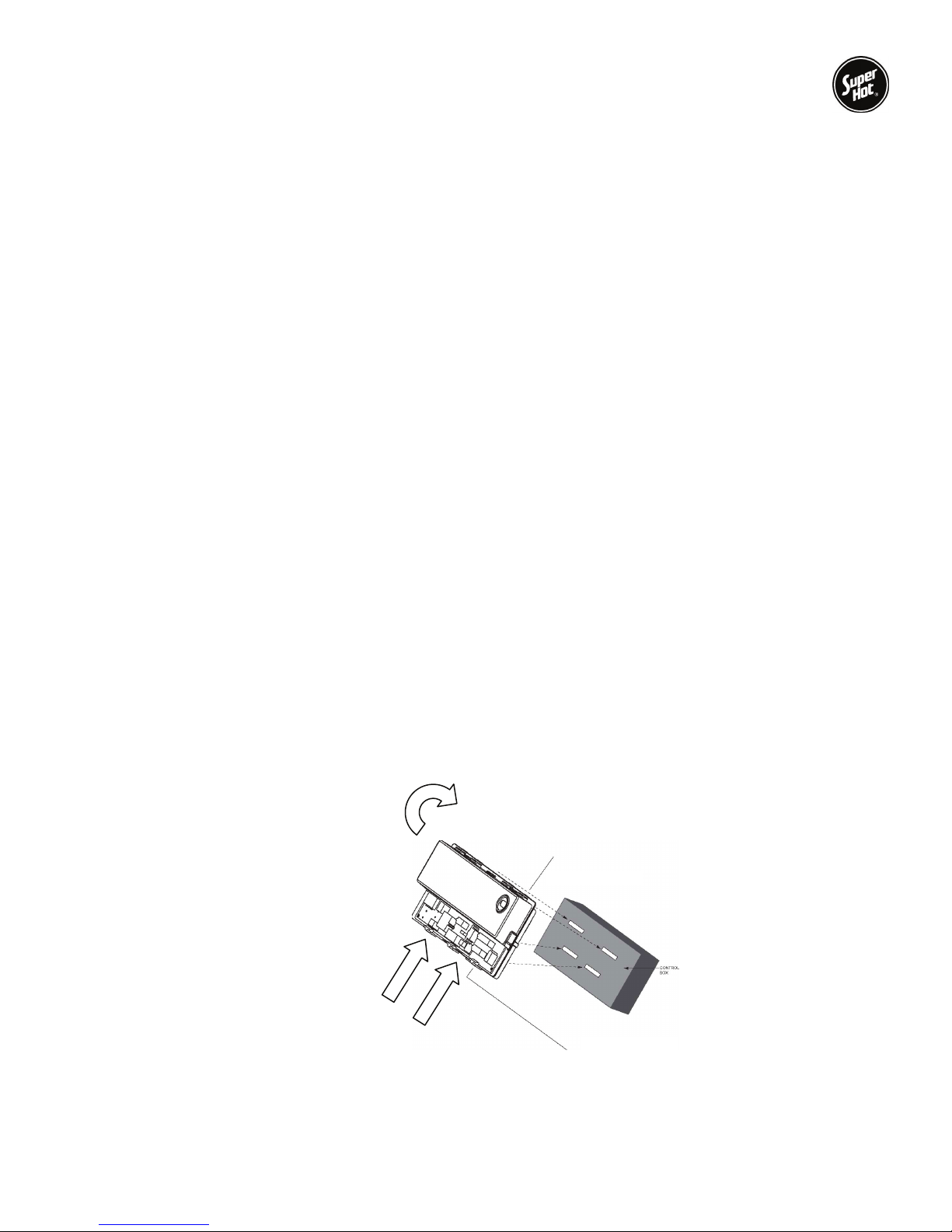
1.6.6 CONTROLLER MOUNTING
The controller has four tabs which align with four slots in the control panel. To remove the controller,
press and hold in the bottom two tabs while simultaneously rotating the controller about 45 degrees to
unhook the top two tabs.
Rotate 45°
PRESS and HOLD
both tabs while
rotating controller
9
SG Series Boilers – Installation and Service Manual
Display
Code
Operation Sequence
StA ↔1
Thermostat Calls For Heat
StA ↔17
Circulator output energizes
StA ↔ 2
StA ↔ 3
StA ↔ 4
StA ↔ 6
StA ↔ 7
StA ↔ 8
Call For Heat Ends
StA ↔ 9
Troubleshooting/Diagnostics
StA ↔10
Err ↔ 2
Err ↔ 29
Err ↔ 62
StA ↔15
StA ↔16
State Specific Description
Idle/Standby The boiler is in standby - no call for heat
Run circulator Heat request present but boiler water temperature sufficiently high to
run circulator pump only (no ignition sequence)
Self Test Hardware self check, check of connected periphery, it is performed
at start up, in the beginning of the heat cycle and in the “Wait For
recovery” state
Wait for recovery There is an external error and the control is waiting to recover, no
lockout
Wait for end switch
to open
Wait for end switch
to close
Pump pre-purge/
thermal purge
Spark, ignition
activation
Prove flame System is proving flame signal, typically 2 seconds
Running System is in running mode, flame signal must be present
Pump post-purge System is purging at the end of a call for heat
Inter-purge
(retry/recycle delay)
Wait for end switch
to open – failed
closed
Wait for end switch
to close – failed
open
Soft lockout System is shutdown and will re-start following an enforced delay
Wait for limit to close
Flame out of
sequence – before
trial
Flame out of
sequence – after
trial
Wait for flame loss Flame signal still present when not expected.
The control is waiting for the end switch of the vent damper to open
at the beginning of a heat cycle. If the end switch doesn’t open in 60
seconds, the control goes to error code Err 2
The control is waiting for the end switch of venting damper to close at
the beginning of a cycle. If the end switch doesn’t close within 60
seconds, the control goes to error code Err 29
System is purging before ignition trial-safety relay diagnostics
followed safety relay switch-on during last 2 seconds this sate
System is sparking permanently 13 seconds whilst pilot gas valve
relay is turned on
If the control loses flame signal during state code 7 or 8, or flame is
not detected during stat code 6 to 8, it will recycle through the 30
seconds purge time and last 2 seconds part of pre-purge time
The end switch of venting damper has not opened at the beginning
of the heat cycle. The control is not in lockout
Waiting time for pressure switch to close expired. The control is not
in lockout
There may be a call for heat from the thermostat, but the limit switch
is open
Flame signal sensed before trial for ignition.
Flame out of sequence during post-purge.
10
SG Series Boilers – Installation and Service Manual
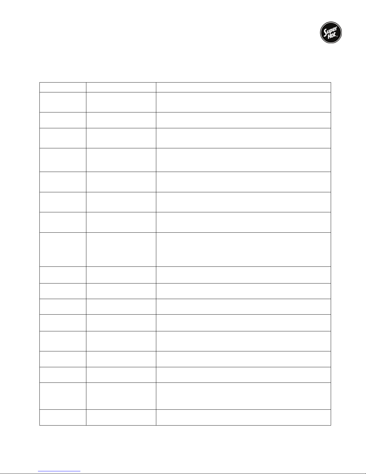
If the controller is displaying “
determine the problem and possible causes.
Table 4 Error Codes
Display State Solution
Err ↔ 2
End switch of venting
damper failed to open
Err” followed by a number, use the error code definitions in the Table 4 to
The end switch contacts stuck closed. Check the venting
damper and replace it if necessary.
Err ↔ 4
Err ↔ 6
Err ↔18
Err ↔ 23
Err ↔ 24
Err ↔ 29
Err ↔ 32
Err ↔ 57
Err ↔ 58
Low flame current
Flame sensed out of
normal sequence
Gas valve relays
welded 5 consecutive
soft lockouts
Flame sensed during
pre-purge
Flame sensed during
post-purge
End switch of venting
damper failed to close
Sensor error
Flame rod shorted to
burner ground
AC line frequency error
Check pilot assembly and replace it if necessary.
Flame sensed out of normal sequence (before opening gas
valve or after closing gas valve).
A manual reset is required.
Flame sensed during pre-purge (before gas valve signaled
opened)
Flame sensed during post-purge (before gas valve signaled
closed)
The end switch contacts stuck open. Check the venting
damper and replace it if necessary.
Temperature sensor or interface failure (open or short
connection, increased connection resistance, dual sensor
mismatch) or failure of A/D conversion (invalid offset or gain,
too many failures during A/D conversion).
Check and adjust or replace if necessary.
AC signal is too noisy or frequency is incorrect.
Err ↔ 59
Err ↔ 60
Err ↔ 61
Err ↔ 62
Err ↔ 63
Err ↔ 64
Err ↔ 65
Line voltage error
Thermostat input
higher than threshold
Line voltage unstable
Soft lockout
Soft lockout
Soft lockout
Over temperature error
AC voltage out of specification high or low.
Check thermostat wiring and replace it if necessary.
Possibly too many heavy loads switching on and off cause
erratic supply voltage.
Maximum number of retries exceeded.
Maximum number of recycles exceeded.
Internal failure (Electronics failure). Caused by general
electronics failure such as relay open or shorted contacts,
flame sensing circuit error, or A to D error.
Sensor measured temperature in excess of ECO limit.
11
SG Series Boilers – Installation and Service Manual
1.7 BC-1 CONTROLLER (FOR 2 STAGE BOILERS ONLY)
WARNING
For boilers equipped with the BC-1 Controller, read all instructions in this manual and the BC-1
Controller Manual before placing the boiler in operation or making adjustments to the
controller. Adjustments must be made by a qualified heating technician.
The BC-1 controller is supplied as standard option with two stage boilers for models SG-315 and larger.
It is not supplied with boilers equipped with a full modulating gas valve. For convenience, the BC-1
controller is factory wired to terminal block TB4 and ready for field wiring connections. The field wiring to
TB4 is determined based on the operating mode selected (i.e. mode 1 to 6), the heating application and
the piping arrangement (i.e. parallel or primary/secondary). Refer to Figure 2 for the wiring diagram
according to each mode. For important instructions regarding programming and operation of the BC-1
controller, refer to the BC-1 Controller Manual included with your boiler.
Power Outputs from BC-1:
Boiler Stage outputs from 15-STG1 and 17-STG2
terminals from the BC-1 are 24 Vac, 60 Hz (when
factory wired).
Alarm output from 23-ALARM terminal from the BC-1 is
24 Vac, 60 Hz, 0.45 A maximum (when factory wired).
Alarm is wired to terminal block TB4, terminals AL&AL.
Signal Inputs (Do not apply external power):
The following signal inputs are located on terminal block TB4:
HT&R: Room thermostat or zone valve end switch,
24Vac switching input, closed is activation.
ST&R: Setpoint DHW aquastat, 24Vac switching
input, closed is activation.
FS&FS: Flow switch, 24Vac switching input, closed
is activation.
Figure 2 – BC-1 Controller
Thermistor Sensors
BO&CM: Boiler outlet sensor
BI&CM: Boiler inlet sensor
OS&CM: Outdoor sensor
SD&CM: Supply / DHW sensor
BC-1 Controller Mounting
The BC-1 controller mounts on separate bracket on the control panel using a sheet metal screw at the top
center. To remove the controller: 1.) remove the front casing panel, 2.) pull off the black top cover of the
controller, 3.) unscrew the sheet metal screw, 4.) lift the controller slightly out of the rectangular cutout in
the mounting bracket, 5.) pull off the Molex connector while simultaneously holding down the tab on the
left side.
12

SG Series Boilers – Installation and Service Manual
Field wiring to terminal block TB4
Figure 3 – Field wiring to terminal block TB4
13
SG Series Boilers – Installation and Service Manual
Electrical Connections
For all electrical connections: Strip wire ends and insert into the terminal block. Tighten terminal screw
clamps to securely hold the wire.
CAUTION - Risk of damage to the controller - Do not apply power to any connections on terminal
block TB4. 24 Vac has been factory wired to terminals C-1 and HL-15.
Terminal
Block
TB4
Connections Name Description / Comments
BO & CM
Boiler Outlet
Sensor
Connect boiler outlet water temperature sensor to terminals
BO and CM (common). The Boiler Outlet Sensor must be
attached using a cable tie to the boiler outlet pipe.
BI & CM
Boiler Inlet
Sensor
Connect inlet water temperature sensor to terminals BI and
CM (common). The Boiler Inlet Sensor must be attached using
a cable tie to the boiler inlet pipe.
OS & CM
Outdoor
Sensor
Optional Outdoor Sensor (for Mode 4 and 5 only): Connect
Outdoor Sensor 070 to terminals OS and CM (common). The
Outdoor Sensor is installed on an exterior wall, typically facing
North, and above the snow line. It should be shielded from
effects of heat or cold to prevent false outdoor temperature
readings. Avoid direct sunlight, exhaust fans, appliance vents,
and excessive moisture.
SD & CM
Supply/DHW
Sensor
Optional (for Modes 2, 3, and 5 only). Connect a Supply or
DHW Sensor 071 to terminals SD and CM (common). The
Supply/DHW sensor is inserted into a thermowell on the DHW
tank or attached using a cable tie to the supply pipe.
AL & AL
Alarm Optional. The alarm contacts are a powered output, do not
apply power. Connect an alarm (beeper, light, or relay) with a
rating of 24 Vac and maximum 0.45 A to terminals AL and AL.
FS & FS
Flow Switch Not used. Leave Jumper 5-6 on TB4. For convenience, the
Flow Switch terminals have been relocated to terminal block
TB2, poles T1 & S. Do not apply power.
ST & R
Setpoint DHW
Demand
Optional Domestic Hot Water Aquastat (for Modes 4 and 5
only): Connect domestic hot water aquastat to terminals ST
and R. Closed is activation. Do not apply power.
HT & R
Heat Demand Connect Thermostat or Zone Valve End Switch to terminals
HT and R. Closed is activation. Do not apply power.
14
 Loading...