

Super Hot MG-50-E-MG-150-E, SG-135-E-SG-495-E, AAA-480-E-AAA-3000-E, MG-50-E, MG-150-E User's Information Manual
...
USER'S INFORMATION MANUAL
GAS BOILERS
FOR MODELS: MG-50-E TO MG-150-E
SG-135-E TO SG-495-E
AAA-480-E TO AAA-3000-E
WARNING:
If the information in this manual is not followed exactly, a fire or
explosion may result causing property damage, personal injury
or loss of life.
→ Do not store or use gasoline or other flammable vapors and liquids in the
vicinity of this or any other appliance.
→ WHAT TO DO IF YOU SMELL GAS
• Do not try to light any appliance.
• Do not touch any electrical switch; do not use any phone in your
building.
• Immediately call your gas supplier from a neighbor’s phone. Follow
the gas supplier’s instructions.
• If you cannot reach your gas supplier, call the fire department.
→ Installation and service must be performed by a qualified installer,
service agency or the gas supplier.
DATE OF INSTALLATION :
INSTALLED BY :
COMPANY :
ADDRESS :
PHONE :
Manufacturers of Gas and Electric Boilers, Stainless Steel Tanks, Heat Exchangers and Electric Boosters.
94 Riverside Drive, North Vancouver, B.C. V7H 2M6 • Telephone (604) 929-1214 • www.alliedboilers.com
PN2362763
H
Manufactured by
Allied Engineering Company
Division of E-Z-Rect Manufacturing Ltd.
Branches: Calgary • Edmonton • Toronto • Denver
MG, SG & AAA Series Boilers – User’s Information Manual
WARNING
Improper installation, adjustment, alteration, service or maintenance can cause property
damage, personal injury (exposure to hazardous materials) or loss of life. Installation and
service must be performed by a qualified installer, service agency or the gas supplier (who
must read and follow the supplied instructions before installing, servicing, or removing this
boiler). This product contains materials (Refractory Ceramic Fibers) that have been identified
as carcinogenic, or possibly carcinogenic, to humans. Follow the Refractory Handling
Procedure instructions in the Installation and Service Manual.
WARNING
It is the responsibility of the homeowner to keep the vent terminal and air supply terminal clear
of snow and ice.
Use of Carbon Monoxide Detectors is recommended. Follow building code requirements with
respect to installation and approvals.
IN THE STATE OF MASSACHUSETTS ONLY
For installations in the Commonwealth of Massachusetts, the following local requirements apply
in addition to all other applicable NFPA requirements:
For direct-vent boilers, mechanical-vent heating appliances or domestic hot water equipment, where the bottom of the vent terminal
and the intake is installed below four feet above grade the following requirements must comply:
1. If not present on each floor level where there are bedrooms, a carbon monoxide detector and alarm must be placed in a living
area outside the bedrooms. The carbon monoxide detector and alarm must comply with NFPA 720 (Current Edition).
2. A carbon Monoxide detector and alarm shall be located in the room that houses the appliance and/or equipment and shall:
a) Be powered by the same electrical circuit as the appliance and/or equipment such that only one service switch services
both the appliance and the carbon monoxide detector;
b) Have battery back-up power;
c) Meet ANSI/UL 2034 Standards and comply with NFPA 720 (Current Edition); and
d) Have been approved and listed by a Nationally Recognized Testing Lab as recognized under 527 CMR.
3. A product-approved vent terminal must be used, and if applicable, a product approved air intake must be used. Installation
shall be performed in strict compliance with the manufacturer’s instructions. A copy of the installation instructions shall remain
with the appliance and/or equipment at the completion of the installation.
4. A metal or plastic identification plate shall be mounted at the exterior of the building, four feet directly above the location of vent
terminal. The plate shall be of sufficient size to be easily read from a distance of eight feet away, and read “Gas Vent Directly
Below”.
For direct-vent boilers, mechanical-vent heating boilers or domestic hot water equipment where the bottom of the vent terminal and
the intake is installed higher than four feet above grade the following requirements must comply:
1. If not present on each floor level where there are bedrooms, a carbon monoxide detector and alarm must be placed in a living
area outside the bedrooms. The carbon monoxide detector and alarm must comply with NFPA 720 (Current Edition).
2. A carbon monoxide detector shall:
a) Be located in the room where the boiler and/or equipment is located;
b) Be either hard-wired or battery powered or both; and,
c) Shall comply with NFPA 720 (Current Edition).
3. A product-approved vent terminal must be used, and if applicable, a product approved air intake must be used. Installation
shall be in strict compliance with the manufacturer’s instructions. A copy of the installation instructions shall remain with the
appliance and/or equipment at the completion of the installation.
2

MG, SG & AAA Series Boilers – User’s Information Manual
1 ABOUT OUR MANUALS
Your Super Hot boiler has been provided with two manuals:
• User's Information Manual - This manual is intended for the owner or user of the boiler and provides
information on routine operation and maintenance, and emergency shutdown.
• Installation and Service Manual - This manual must only be used by a qualified heating installer,
service technician or gas supplier. Installation or service by anyone unqualified to do so may
result in severe personal injury, death or substantial property damage.
Both manuals should be kept in the envelope provided and affixed adjacent to the boiler so that they are
readily available for future reference.
2 SAFETY INSTRUCTIONS
WARNING
If you do not follow these instructions exactly, a fire or explosion may result causing property
damage, personal injury or loss of life.
A. BEFORE LIGHTING smell all around the
boiler area for gas. Be sure to smell next to
the floor because some gas is heavier than
air and will settle on the floor.
WHAT TO DO IF YOU SMELL GAS
• Do not try to light any appliance.
• Do not touch any electrical switch; do not
use any phone in your building.
• Immediately call your gas supplier from a
neighbor's phone. Follow the gas
supplier's instructions.
• If you cannot reach your gas supplier,
call the fire department.
B. Use only your hand to push in or turn the gas
control knob. Never use tools. If the knob will
not push in or turn by hand, don't try to repair
it, call a qualified service technician. Force or
attempted repair may result in a fire or
explosion.
C. Do not use this boiler if any part has been
under water. Immediately call a qualified
service technician to inspect the appliance
and to replace any part of the control system
and any gas control which has been under
water.
3 LIGHTING INSTRUCTIONS
Your boiler is equipped with one of two optional electronic ignition systems. Determine the ignition
system that applies from the list below and go to the applicable lighting instruction section.
• Intermittent electronic ignition with combination gas valve for MG-50-E to SG-400-E (Section 4)
• Intermittent electronic ignition with non-combination gas valve for SG-450-E to AAA-3000-E
(Section5)
Note: A combination gas valve combines the operating and safety shut-off into one valve body and is
typical in residential installations. A non-combination gas valve system utilizes two separate valve
bodies for operating and safety shut-off and is typical in commercial installations.
If you are unsure which type of gas valve your boiler is equipped with, check the lighting instructions
sticker on the boiler or contact the factory.
3
MG, SG & AAA Series Boilers – User’s Information Manual
4 LIGHTING INSTRUCTIONS FOR INTERMITTENT ELECTRONIC IGNITION
WITH COMBINATION GAS VALVE.
1. This boiler is equipped with an ignition device
which automatically lights the pilot. Do not
to light the pilot by hand. Ensure gas supply
to the boiler is turned on.
2. STOP! Read the safety instructions in
Section 2.
3. Set the room thermostat to lowest setting.
4. Turn off all electrical power to the appliance.
5. Remove control access panel if necessary.
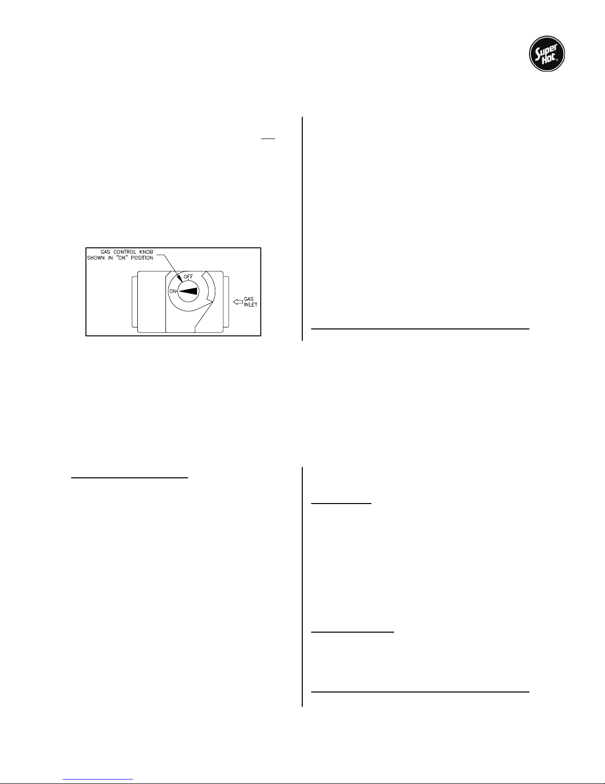
6. Push in gas control knob slightly and turn
clockwise
to "OFF".
try
NOTE: On some gas valves the knob cannot
be turned to "OFF" or “ON” position unless
knob is pushed in slightly. Do not force.
7. Wait five (5) minutes to clear out any gas.
Then smell for gas, including near the floor.
If you smell gas, STOP! Follow "A" in the
safety instructions in Section 2. If you don't
smell gas, go to the next step.
8. Turn gas control knob counterclockwise
to "ON".
9. Replace control access panel if necessary.
10. Turn on all electrical power to the Boiler.
11. Set room thermostat to desired setting.
12. If the appliance will not operate, follow the
instructions "To Turn Off Gas To Boiler" in
Section 7 and call your service technician or
gas supplier.
To turn off gas to boiler or emergency shut-off
Follow Section 6.
5 LIGHTING INSTRUCTIONS FOR INTERMITTENT ELECTRONIC IGNITION
WITH NON-COMBINATION GAS VALVE.
This boiler is equipped with an ignition device, which automatically lights the pilot. Do not try to light the
pilot by hand. Before turning on the electrical power switch, be sure all gas supply lines are purged of air
and power supply to control is the correct voltage.
If the pilot or main burners are not lit or the control system is locked-out due to flame failure, close the
main and pilot gas shut-off valves and call your service technician or gas supplier. If you smell gas,
STOP! Follow “A” in the safety instructions in Section 2.
Check Control Operation
1. STOP! Read the safety instructions in
Section 2.
2. For 100% shut off check, close main and pilot
manual gas shut off valves, turn off all electric
power to the boiler and wait for five minutes to
clear out any gas.
3. Then smell for gas, including near the floor. If
you smell gas, STOP! Follow safety instructions
in Section 2. If you don’t smell gas, go to the
next step.
4. Set the thermostat above room temperature
and turn on all electric power to the boiler to
energize the electronic ignition and pilot valve.
After a few seconds, the control system
should “lockout” and all functions are off.
5. To take the control system out of “lockout”
either press the reset button or interrupt power
to the boiler, depending on the boiler
controller. Some controllers will retry ignition
automatically after 5 minutes lockout.
Start System
1. Turn on the main and pilot manual gas shutoff valves.
2. Set thermostat above room temperature and
turn on all electrical power to the boiler.
3. Once the pilot flame is proven, the controller
opens the main burner gas valves. The pilot
flame will ignite the gas as it exits the main
burner ports.
4. Set thermostat to the desired setting to put
system back in service.
Relight Operation
Five minutes complete shut off period is required
before attempting to relight the boiler. To relight
the boiler, follow the Start System procedure
(above).
To turn off gas to boiler or emergency shut-off
Follow Section 6.
4
 Loading...