

PN7362112
INSTALLATION AND SERVICE MANUAL
Model: HSE–125–N/P, HSE–145–N/P
Gas-fired Condensing Boiler and
Instantaneous Water Heater
WARNING
If the information in this manual is not followed exactly, a fire or explosion may result causing
property damage, personal injury or loss of life.
• Do not store or use gasoline or other flammable vapors and liquids in the vicinity of this or any
other appliance.
• WHAT TO DO IF YOU SMELL GAS
- Do not try to light any appliance.
- Do not touch any electrical switch; do not use any phone in your building.
- Immediately call your gas supplier from a neighbor’s phone. Follow the gas supplier’s
instructions.
- If you cannot reach your gas supplier, call the fire department.
• Installation and service must be performed by a qualified installer, service agency or the gas
supplier.
• Improper, installation, adjustment, alteration, service or maintenance can cause property damage,
personal injury or loss of life. Read all instructions before installation or service.
• Save this manual for future reference.
Manufacturers of Gas and Electric Boilers, Stainless Steel Tanks, Heat Exchangers and Electric Boosters.
94 Riverside Drive, North Vancouver, BC V7H 2M6 • Tel: (604) 929-1214 • www.alliedboilers.com
Allied Engineering Company
Division of E-Z-Rect Manufacturing Ltd.

HSE Installation and Service Manual
Table of Contents
Section Page
About Our Manuals ....................................................................................................................................... 5
Abbreviations and Names Used ................................................................................................................... 5
Icons.............................................................................................................................................................. 5
Technical Support ......................................................................................................................................... 5
Technical Specifications ............................................................................................................................... 6
Major Components........................................................................................................................................ 8
Dimensions ................................................................................................................................................... 9
Description of Appliance ............................................................................................................................. 10
Section 1 – Installation Instructions .......................................................................................................11
1.1 Receiving, Moving and Unpacking ................................................................................................ 11
1.2 Installation Codes and Requirements............................................................................................ 11
1.3 Location and Installations .............................................................................................................. 12
1.3.1 Location.......................................................................................................................................... 12
1.3.2 Minimum Service Clearances ........................................................................................................ 12
1.3.3 Installation in a Kitchen Cupboard or Closet.................................................................................. 12
1.3.4 Installation in an Airing Cupboard or Closet ..................................................................................12
1.3.5 Remove Front Panel ...................................................................................................................... 13
1.3.6 Mounting ........................................................................................................................................ 13
1.3.7 Install the Condensate Trap........................................................................................................... 14
1.4 Water Piping Systems.................................................................................................................... 14
1.4.1 CH Piping System (Boiler) ............................................................................................................. 15
1.4.1.1 CH Piping Connections.................................................................................................................. 15
1.4.1.2 Pressure Relief Valve .................................................................................................................... 16
1.4.1.3 Manual Shutoff Valves ................................................................................................................... 16
1.4.1.4 Expansion Tank and Make-Up Water............................................................................................ 16
1.4.1.5 System Bypass and Pressure Head Losses.................................................................................. 16
1.4.1.6 Corrosion Prevention (Internal)...................................................................................................... 17
1.4.2
1.4.2.1 DHW Piping Connections ..............................................................................................................17
1.4.2.2 DHW Piping with a Backflow Preventer......................................................................................... 18
1.4.2.3 Pressure Relief Valve or Temperature and Pressure Relief Valve ............................................... 18
1.4.2.4 Cathodic Protection Devices.......................................................................................................... 18
1.4.3 Appliance Used with Solar System ................................................................................................ 18
1.5 Gas Service Piping......................................................................................................................... 18
1.6 Electric Connection ........................................................................................................................ 19
1.7 Venting and Combustion Air .......................................................................................................... 21
1.7.1 Corrosive Atmosphere ................................................................................................................... 22
1.7.2 Air Intake System ........................................................................................................................... 22
1.7.3 Exhaust Vent System..................................................................................................................... 22
1.7.4 Vent Terminal Information.............................................................................................................. 23
1.7.5 Direct Vent Configurations .............................................................................................................26
1.7.5.1 Twin Tube to Appliance Connection .............................................................................................. 26
1.7.5.2 Concentric to Appliance Connection.............................................................................................. 26
1.7.6 Equivalent Vent/Air Intake Tube Length and Diameters................................................................ 27
1.7.7 Example of 3 Inch (80 mm) Diameter Twin Tube Calculation ....................................................... 28
1.7.8 Example of 3/5 Inch (80 mm/125mm) Diameter Concentric Tube Calculation ............................. 28
DHW Piping System (Water Heater) ............................................................................................. 17
2

HSE Installation and Service Manual
1.7.9 Vent Installations............................................................................................................................ 29
1.7.9.1 Horizontal Twin Tube Side Venting with Twin Terminal Caps....................................................... 30
1.7.9.2 Vertical (Roof Top) Twin Tube Venting with Twin Terminal Caps................................................. 30
1.7.9.3 Vertical (Roof Top) Twin Tube Venting with Air Supply from Side Wall ........................................ 31
1.7.9.4 Concentric Connections with a Combined Terminal Cap.............................................................. 32
Section 2 – Controller............................................................................................................................... 34
2.1 Controller Operation....................................................................................................................... 34
2.2 PC Interface ................................................................................................................................... 37
2.3 Test Programs and Frost Protection.............................................................................................. 37
2.3.1 Test Programs................................................................................................................................ 37
2.3.2 Frost Protection.............................................................................................................................. 37
2.4 Setting and Adjustment.................................................................................................................. 38
2.4.1 User Parameter Settings................................................................................................................ 38
2.4.2 Installer Parameter Settings........................................................................................................... 39
2.4.3 Setting and Description of Parameters .......................................................................................... 40
2.4.4 Setting CH and DHW Operating Input Rating................................................................................ 42
2.4.5 Pump Head and Pressure Drop of CH H.E. ..................................................................................42
2.4.6 Outdoor Reset Function................................................................................................................. 43
Section 3 – Startup Instructions.............................................................................................................. 44
3.1 CH System Operating Requirements ............................................................................................ 44
3.2 Pre-Startup..................................................................................................................................... 44
3.2.1 CH System ..................................................................................................................................... 44
3.2.2 DHW System.................................................................................................................................. 45
3.2.3 Gas Supply..................................................................................................................................... 45
3.3 Startup............................................................................................................................................ 45
3.3.1 Lighting Instructions ....................................................................................................................... 46
3.3.2
3.3.3 Sequence of Control Operation .....................................................................................................47
3.4 Check Burner System .................................................................................................................... 48
3.5 Conversion to Propane .................................................................................................................. 49
3.6 Setting of Gas-Air Ratio ................................................................................................................. 49
3.6.1 Adjust the Gas-Air Ratio by Measuring the CO
3.7 Appliance for Use at High Altitude ................................................................................................. 51
3.8 Check Input Rating ........................................................................................................................ 52
3.9 Check for Controls ......................................................................................................................... 52
3.10 Check for Gas Leaks ..................................................................................................................... 52
3.11 Check the Condensate Trap.......................................................................................................... 52
3.12 Installer’s Checklist ........................................................................................................................53
Section 4 – Service & Maintenance Instructions ................................................................................... 54
4.1 Service & Maintenance Instructions .............................................................................................. 54
4.2 Service Procedure ......................................................................................................................... 54
4.2.1 Check Appliance Area ................................................................................................................... 54
4.2.2 Inspect the Condensation Trap and Discharge Tube .................................................................... 55
4.2.3 Check the Water and Gas Piping Systems.................................................................................... 55
4.2.4 Check the Pressure Relief Valves .................................................................................................55
4.2.5 Check all Wiring ............................................................................................................................. 55
4.2.6 Service the Venting System........................................................................................................... 55
4.2.7 Service the Heat Exchanger if necessary...................................................................................... 56
4.2.8 Check the Operation of the Appliance ........................................................................................... 56
4.2.8.1 Check the Control Settings ............................................................................................................ 56
Startup Instructions ........................................................................................................................ 47
Percentage of the Flue ...................................... 50
2
3

HSE Installation and Service Manual
4.2.8.2 Check the Gas-Air Ratio ................................................................................................................ 56
4.2.8.3 Check Burner Flame ...................................................................................................................... 57
4.2.9 Completion of Inspection and Service ........................................................................................... 57
4.2.10 Review the Service with Owner ..................................................................................................... 57
4.3 Service Checklist............................................................................................................................ 58
4.4 Caution: Water Replenishment ...................................................................................................... 59
4.5 Refractory Handling Procedure ..................................................................................................... 59
Section 5 – Replacement Parts................................................................................................................ 60
Section 6 – Troubleshooting Guide ........................................................................................................61
6.1 Possible Problems and Solutions ..................................................................................................61
6.2 Burner Fails to Ignite ...................................................................................................................... 62
6.3 Burner Ignites with Noise ............................................................................................................... 63
6.4 Burner Resonates .......................................................................................................................... 63
6.5 No Heating (CH)............................................................................................................................. 64
6.6 Reduced Output ............................................................................................................................. 64
6.7 CH Supply Water Does Not Reach Correct Temperature ............................................................. 65
6.8 No Domestic Hot Water (DHW) ..................................................................................................... 65
6.9 Domestic Hot Water Does Not Reach Correct Temperature ........................................................ 66
6.10 NTC Temperature Sensors Data ................................................................................................... 66
Section 7 – Notes ...................................................................................................................................... 67
4

HSE Installation and Service Manual
ABOUT OUR MANUALS
Your Super Hot Intergas appliance has been provided with two manuals:
• User's Information Manual - This manual is intended for the ow
provides information on routine operation and maintenance, and emergency shutdown.
• Installation and Service Manual - This manual must only be used by a qualified heating installer,
service technician or gas supplier. Installation or service by anyone unqualified to do so may
result in severe personal injury, death or substantial property damage.
Both manuals should be kept in the envelope provided and affixed adjacent to the appliance so that they
are readily available for future reference.
ner or user of the appliance and
ABBREVIATIONS AND NAMES USED
Description Referred to as
HSE condensing boiler and water heater Appliance
Central heating CH
Domestic hot water DHW (also HW)
Appliance with piping for central heating (boiler) CH system
Appliance with piping for domestic hot water heating DHW system
ICONS
The following symbols may be used in this manual:
DANGER
WARNING
CAUTION
CAUTION
NOTICE
DANGER indicates a potentially hazardous situation which, if not avoided, will
result in death or serious injury.
WARNING indicates a potentially hazardous situation which, if not avoided, could
result in death or serious injury.
CAUTION indicates a potentially hazardous situation which, if not avoided, could
result in minor or moderate injury.
CAUTION indicates a potentially hazardous situation which, if not avoided, may
result in property damage.
Special instructions which are important but not related to personal injury or
property damage.
TECHNICAL SUPPORT
For information about specific adjustments, installation, maintenance and repair activities, please contact
Allied Engineering Company.
5
HSE Installation and Service Manual
TECHNICAL SPECIFICATIONS
Technical data
CH (central heating – BOILER)
Nominal input rate* 1000 Btu/h (kW) 28.7 – 124 (8.4 – 36.3)
Nominal output rate 1000 Btu/h (kW) 27.3 – 118 (8.0 – 34.5)
AFUE % 95
Maximum CH operating pressure psi (bar) 43 (3.0)
Maximum CH operating temperature °F (°C) 194 (90)
DHW (domestic hot water – HEATER)
Nominal input rate* 1000 Btu/h (kW) 28.7–124 (8.4 – 36.3)
Nominal output rate 1000 Btu/h (kW) 25.3 – 109 (7.4 – 31.9)
Energy Factor (EF)** 0.88 0.91
DHW minimum flow rate USGPM (l/min) 0.53 (2.0)
DHW continuous delivery at 135°F (with 77 ºF water temperature rise) USGPM (l/min) 2.8 (10.7)
DHW continuous delivery at 120 °F ( with 60 ºF water temperature rise) USGPM (l/min) 3.6 (13.7)
Maximum DHW temperature °F (°C) 150 (65)
HSE-125-N HSE-125-P
Natural Gas Propane
Electrical data
Mains voltage / frequency Vac / Hz 120 / 60
Consumed power: full load W 110
Consumed power: standby W 10
Overall dimensions and weight
Height inch (mm) 31.9 (810)
Width inch (mm) 17.7 (450)
Depth inch (mm) 10.6 (270)
Weight lbs (kg) 86 (39)
Connections
CH supply inch NPT male ¾
CH return inch NPT male ¾
DHW supply inch NPT male ½
Cold water for DWH inch NPT male ½
Gas inch NPT male ½
Condensate drain flexible pipe, outside diameter inch (mm) 1 (25)
Air supply inlet (without adapter installed) mm 80
Flue gas outlet (without adapter installed) mm 80
Air supply inlet with adapter installed inch 3
Flue gas outlet with adapter installed inch 3
* The CH & DHW input rate is set to 100 % by default (see Setting CH & DHW input rating).
** The energy factor (EF) is the ratio of energy delivered to the water as compared to the total energy consumed.
Note: NPT = National Pipe Thread
6

HSE Installation and Service Manual
TECHNICAL SPECIFICATIONS
Technical data
CH (central heating – BOILER)
Nominal input rate* 1000 Btu/h (kW) 33 – 145 (9.7 – 42.5)
Nominal output rate 1000 Btu/h (kW) 31 – 136 (9.1 – 39.9)
AFUE % 94
Maximum CH operating pressure psi (bar) 43 (3.0)
Maximum CH operating temperature °F (°C) 194 (90)
DHW (domestic hot water – HEATER)
Nominal input rate* 1000 Btu/h (kW) 33 – 145 (9.7 – 42.5)***
Nominal output rate 1000 Btu/h (kW) 29 – 128 (8.5 – 37.4)
Energy Factor (EF)** 0.88 0.91
DHW minimum flow rate USGPM (l/min) 0.53 (2.0)
DHW continuous delivery at 135°F (with 77 ºF water temperature rise) USGPM (l/min) 2.8 (10.7)
DHW continuous delivery at 120 °F ( with 60 ºF water temperature rise) USGPM (l/min) 3.6 (13.7)
Maximum DHW temperature °F (°C) 150 (65)
HSE-145-N HSE-145-P
Natural Gas Propane
Electrical data
Mains voltage / frequency Vac / Hz 120 / 60
Consumed power: full load W 150
Consumed power: standby W 10
Overall dimensions and weight
Height inch (mm) 31.9 (810)
Width inch (mm) 17.7 (450)
Depth inch (mm) 10.6 (270)
Weight lbs (kg) 86 (39)
Connections
CH supply inch NPT male ¾
CH return inch NPT male ¾
DHW supply inch NPT male ½
Cold water for DWH inch NPT male ½
Gas inch NPT male ½
Condensate drain flexible pipe, outside diameter inch (mm) 1 (25)
Air supply inlet (without adapter installed) mm 80
Flue gas outlet (without adapter installed) mm 80
Air supply inlet with adapter installed inch 3
Flue gas outlet with adapter installed inch 3
* The CH input rate is set to 100% & DHW to 85% by default (see Setting CH & DHW input rating).
** The energy factor (EF) is the ratio of energy delivered to the water as compared to the total energy consumed.
*** The DHW Booster function operates at an input rate of 145,000 Btu/h (42.5 kW) for the first 2min after which the DHW input
rate drops to 124,000 Btu/h (36.3 kW)
Note: NPT = National Pipe Thread
7
HSE Installation and Service Manual
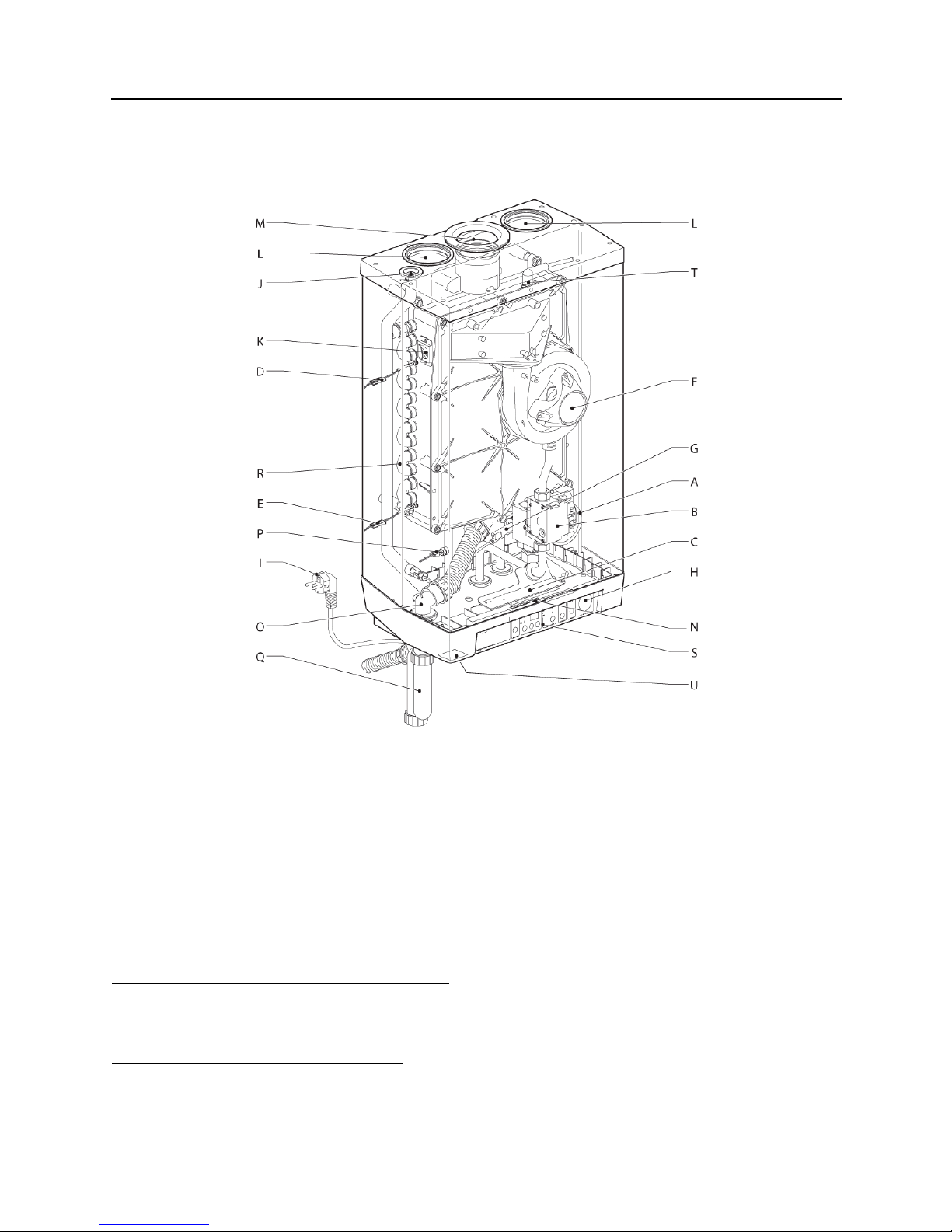
MAJOR COMPONENTS
A CH pump M Flue discharge
B Gas valve N Wiring connecting block / terminal
C Burner controller with operating panel O Condensate discharge
D Supply sensor S1 P DHW sensor S3
E Return sensor S2 Q Condensate trap
F Blower R Heat exchanger
G DHW Flow switch S Operating and display panel
H CH Pressure gauge T Ionisation/ignition probe
I N/A U Front cover fixing screw
J CH manual air vent V High limit S7 (not shown)
K Sight glass and mirror for checking flame W Flue sensor S8 (not shown)
L Air supply
Additional Components (supplied with appliance)
1 Compression fittings for CH pipes 4 Wall mounting strip
2 Vent adapters - 80mm to 3” CPVC 5 Pressure relief valve, 30 psi
3 Outdoor sensor 6 Drain valve
Optional Accessories (ordered separately)
1 DHW kit - includes compression fittings 3 Propane conversion kit
for DHW pipes, 125 psi PRV, etc. 4 Mounting frame
2 Condensate Neutralization Kit 5 Computer interface cable for diagnostics
8
HSE Installation and Service Manual
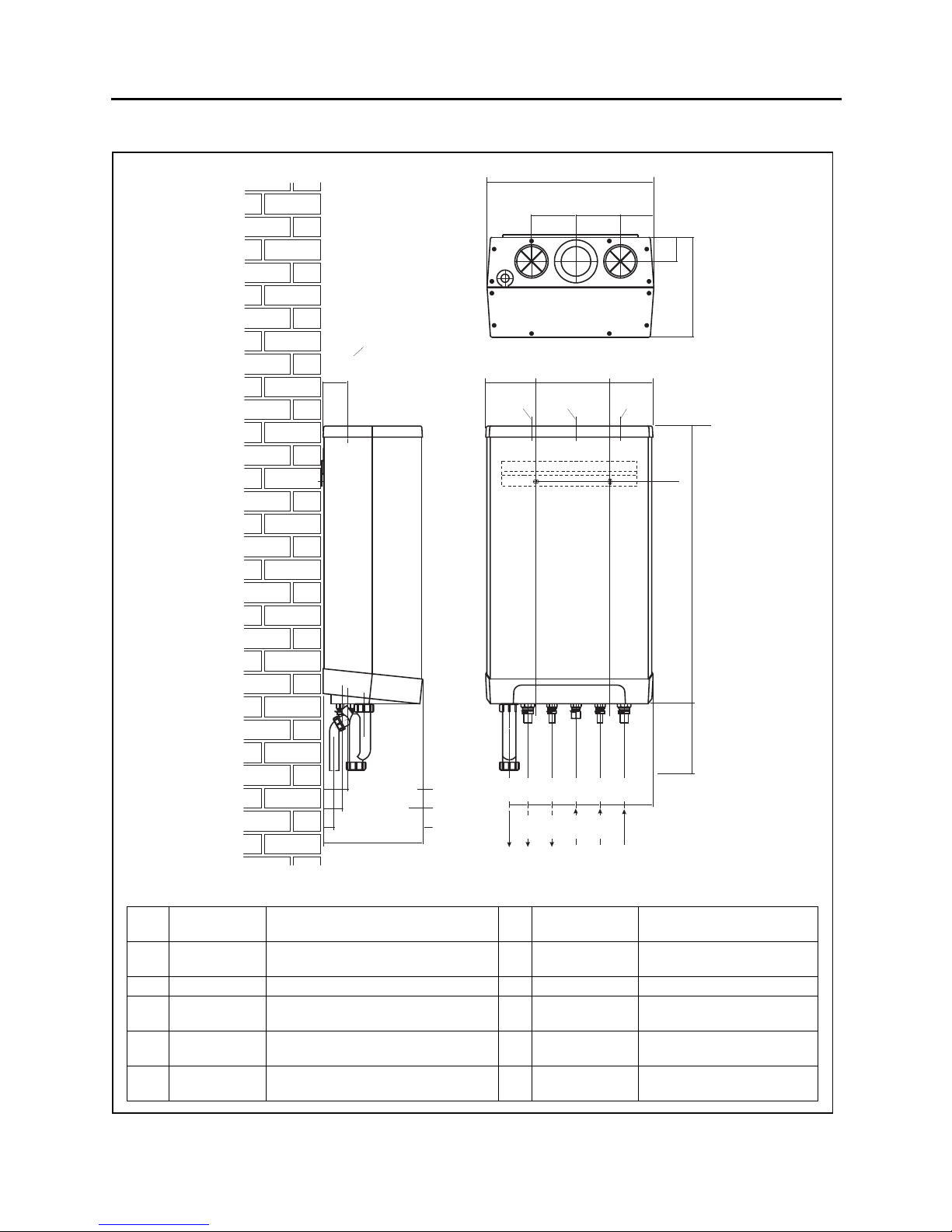
DIMENSIONS
Y, Z
2.6”
65mm
120mm
5.3”
135mm
YZ
17.7”
450mm
4.7”
7.9”
200mm
4.7”
120mm
3.5”
90mm
4.5”
115mm
Y
2.6”
5.9”
150mm
65mm
10.6”
270mm
2.6” [65mm]
2.0” [50mm]
1.2/1.4”[30/35mm]
10.6” [270mm]
A,B,C
D,E
F
2.0”
50mm
F
2.6”
65mm
A E
2.6”
65mm
2.6”
65mm
C
2.6”
65mm
D
A= CH supply
B= CH return
C= Gas ½” NPT male
Cold water
D=
for DHW
E= DHW
F= Condensate 1” (25mm) diameter flexible tube Z= Flue gas outlet
22mm diameter pipe
(fitting is 22mm to 3/4" NPT male)
22mm diameter pipe
(fitting is 22mm to 3/4" NPT male)
15 mm diameter pipe
(fitting is 15mm to ½" NPT male)
15 mm diameter pipe
(fitting is 15mm to ½" NPT male)
* HSE-145
Y= Air supply inlet
31.9”
810mm
7.5”
190mm
3.2”
80mm
B
80 mm diameter
(with vent adapter: 3”)
80 mm diameter
(with vent adapter: 3”)
*11.8"
300mm
9

HSE Installation and Service Manual
DESCRIPTION OF THE APPLIANCE
The Super Hot Intergas HSE is a combined high efficiency condensing boiler and instantaneous water
heater that is designed for providing Central Heating (CH) and/or Domestic Hot Water (DHW). The actual
required input rate for CH and DHW can be independently programmed lower than the maximum input
rate to match the user’s design heating load and required DHW supply. During operation, the input rate
will be automatically modulated to satisfy the central heating or domestic hot water demand.
The heat exchanger is constructed of two separated copper tube circuits (i.e. CH and DHW) embedded in
high-pressure cast aluminium. This design protects against corrosion by using copper tube to contain
system water and aluminium to condense flue gases. The DHW system eliminates typical standby heat
losses as compared to hot water tanks, isolates the domestic hot water from potential contamination as
compared to a single wall indirect tank or flat plate heat exchanger, and has a higher efficiency as
compared to a direct-fired hot water tank.
Because of the separated circuits for CH and DHW, the heating and the hot water supply operate
independently of each other. The hot water supply has priority over the central heating if both systems
are connected; they cannot work simultaneously. It is possible to use the appliance solely for hot water or
solely for heating with the unused system not connected. Also, the DHW circuit can be connected to a
storage hot water tank, but cannot be connected to a closed system (e.g. the coil of an indirect hot water
tank).
The appliance is equipped with an electronic controller to energize the pump, control the blower, open the
gas valve, ignite the burner, continuously monitor the flame and modulate the input rate to match the
current heat demand.
The appliance is certified as a direct vent (balanced flue) only. The combustion air supply and flue
discharge can be connected to the appliance by means of two separate pipes or a concentric connection.
The appliance must be wall mounted and can be mounted using either the supplied wall mounting strip or
the optional wall mounting frame. The frame provides the spacing needed for a large elbow when venting
through the sidewall on which it is mounted. Also, the frame can hold a square expansion tank and
allows piping to pass behind the appliance for a very compact installation. The wall mounting frame and
expansion tank are supplied separately.
The appliance is factory equipped for natural gas. An optional propane conversion kit, included with
conversion instructions, can be supplied upon request.
The appliance includes standard parts for connection to a central heating (CH) system. For connection to
domestic hot water heating (DHW) system, the DHW kit must be used with the appliance and can be
supplied upon request.
Using the appliance for any other application which is outside of the scope is not covered by the warranty.
10

HSE Installation and Service Manual
Installation Instructions Section 1
1.1 RECEIVING, MOVING AND UNPACKING
INSPECT SHIPMENT FOR POSSIBLE DAMAGE. All goods are carefully manufactured, inspected,
checked and packed by experienced workers. The manufacturer's responsibility ceases upon delivery of
goods to the carrier in good condition. Any claims for
damage and/or shortage in shipment or non-delivery must
be filed immediately against the carrier by the consignee.
Use care when receiving, moving and unpacking the
appliance. Dropping the appliance may cause damage and
prevent safe and proper operation. Only transport the
appliance using the right transportation equipment, such as
a hand truck with a fastening belt or special equipment for
maneuvering steps. During transportation, observing the
transportation markings on the packaging and securing the
appliance on the transportation equipment to prevent it
from falling off.
Unpacking the appliance and check the parts packaged in
the carton with the appliance. The appliance, mounting
strip, condensate trap, installation instructions and warranty
card are included in the carton. Refer to Figure 1.
Figure 1 Appliance with parts
1.2 INSTALLATION CODES AND REQUIREMENTS
All applicable national, provincial/state, and local codes, laws, regulations, and ordinances must be
followed. They expand on and take precedence over any recommendations in this booklet. Authorities
having jurisdiction shall be consulted before installations are made.
In Canada, the installation must conform to the requirements of the authority having jurisdiction or, in the
absence of such requirements, to the Natural Gas and Propane Installation Code (current edition),
CAN/CSA B149.1. All electrical wiring and grounding must be in accordance with the Canadian Electrical
Code, CSA C22.1 Part 1 (current edition) and applicable local codes.
In the United States of America, the installation must conform to the requirements of the authority
having jurisdiction or, in the absence of such requirements, to the National Fuel Gas Code, ANSI
Z223.1/NFPA 54 (current edition). All electrical wiring and grounding must be in accordance with the
National Electrical Code, ANSI/NFPA 70 (current edition) and applicable local codes.
Where required by the authority having jurisdiction, follow the Standard for Controls and Safety Devices
for Automatically Fired Boilers, ANSI/ASME CSD-1 (current edition).
If there is any conflict in the above requirements, the more stringent requirement applies.
The installation and service must also conform to the additional requirements in this manual. If there is
any conflict with a requirement in this manual and a Code requirement, the Code requirement must be
followed.
The hot water distribution system must comply with all applicable codes and regulations. When replacing
an existing appliance, it is important to check the condition of the entire hot water distribution system to
ensure safe operation.
Some jurisdictions may require that flue condensate be neutralized prior to disposal because flue
condensate is very corrosive and will corrode most metals.
11
HSE Installation and Service Manual
1.3 LOCATION AND INSTALLATION
1.3.1 LOCATION
This appliance is intended for an indoor, wall hung installation using the wall mounting strip or
optional mounting frame. The appliance should be mounted on a wall with sufficient bearing
strength. In the case of light wall constructions, resonance sounds may occur.
In order to avoid freezing of the condensate discharge, the appliance should be installed in a
frost-free room.
A hot water boiler installed above radiation level, or as required by the authorities having
jurisdiction, must be provided with a low water cutoff device at the time of boiler installation.
This appliance must be installed such that gas ignition system components are protected from
water (dripping, spraying, rain, etc.) during appliance operation and service (circulator
replacement, condensate trap, control replacement, etc.).
Structure through which venting will pass must be free and clear for opening (i.e. no hidden
conduit, telephone cables or other obstructions).
1.3.2 MINIMUM SERVICE CLEARANCES
Minimum clearances from appliance casing to combustible materials are zero
reasonable space must be provided for ventilation. Recommended minimum clearances for
service are listed in table 1.
Table 1 Recommended Minimum Service Clearances
Recommended Minimum Service Clearances
Left/right side
without piping
in. mm in. mm in. mm in. mm in. mm in mm
1 25 24 700 0 0 28 700 7 178 10 254
- Flue Vent Clearance = 1 inch (25 mm)
- Hot Water Pipe Clearance = 1 inch (25 mm)
Left/right side
with piping
Rear Front Top Bottom
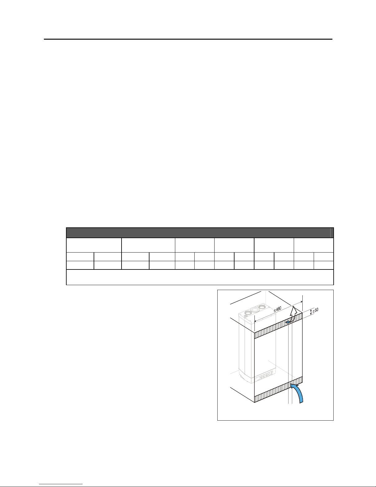
1.3.3 INSTALLATION IN A KITCHEN CUPBOARD OR
CLOSET
Make sure there is sufficient ventilation above and
below the appliance.
When the appliance is placed in a small cupboard,
ventilation openings of at least 8 in
2
(50 cm2) must be
made. Refer to Figure 2.
1.3.4 INSTALLATION IN AN AIRING CUPBOARD OR
CLOSET
however
Compartment ventilation is not required
standard airing cupboard or closet (e.g. 24 x 24 x
91in high or 0.6 x 0.6 x 2.3m high).
for a
Figure 2 Install in kitchen cupboard or
closed closet
12
HSE Installation and Service Manual
g
A
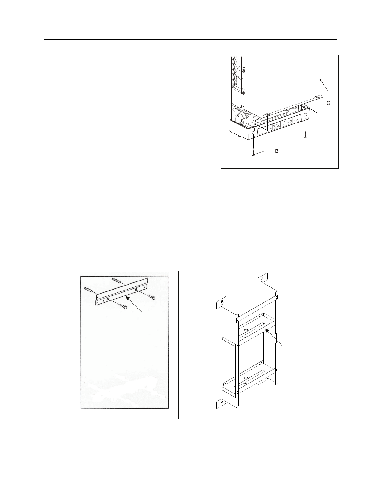
1.3.5 REMOVE FRONT COVER
Remove the front cover on the appliance as follows,
refer to Figure 3:
1. Unscrew both screws (B) at the bottom of the
appliance.
2. Lift the front panel (C) and remove it forward.
1.3.6 MOUNTING
There are two types of mounting methods. Wall
mounting strip (A) is the standard appliance mounting
bracket and wall mounting frame (B) is an optional
mounting frame which holds a square expansion
tank. For mounting the appliance on the inside of an
external wall through which sidewall venting passes,
wall mounting frame (B) is recommended to provide
sufficient clearance for venting elbows.
Option One – Wall mounting strip (A) Only (Refer to Figure 4)
1. Use the screws and plugs supplied to fasten the bracket horizontally to the wall.
2. Hang the appliance by sliding it top-down over the standard mounting strip.
3. Install the parts of the various connecting sets.
Figure 3 Remove front cover
Option Two – Mounting frame (B) (Refer to Figure 5)
1. Use the screws and plugs supplied to fasten the mounting frame (B) vertically to the wall.
2. Connect the expansion tank to the heating system before connecting appliance piping.
3. Hang the appliance by sliding it top-down over the mounting frame.
4. Install the parts of the various connecting sets.
ure 4 Wall mounting strip
Fi
B
Figure 5 Mounting frame
13
HSE Installation and Service Manual
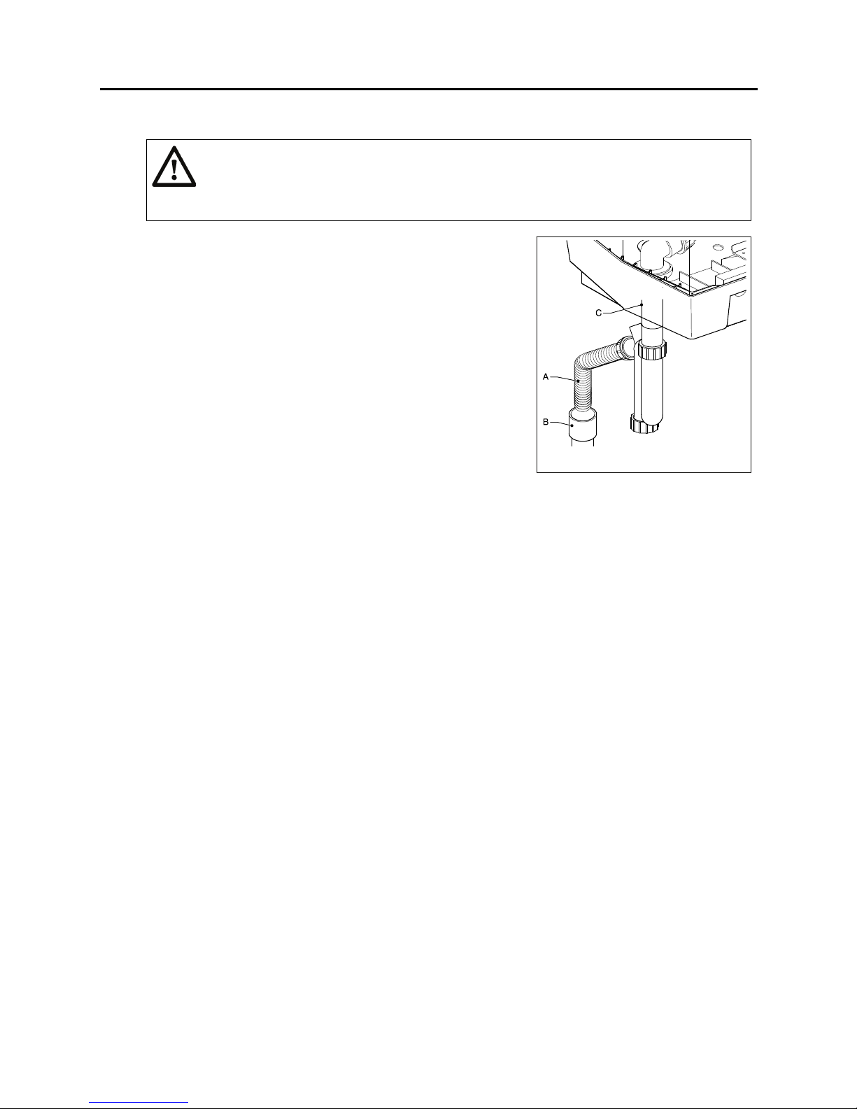
1.3.7 INSTALL THE CONDENSATE TRAP (Refer to Figure 6)
WARNING
Risk of exhaust gases escaping to the appliance room! The condensate trap must
always be filled with water or condensate so that it forms a liquid-filled trap. Check the
trap and, if low, fill it until water begins to pour out of the drain.
Install the condensate trap to the condensate outlet pipe (C)
and tighten union.
The flexible tube (A) from the condensate trap should be
inserted into an open waste pipe (B) of not less than 1-1/4
inch (32 mm) diameter or a neutralization unit. If connected
to a soil pipe or waste system, the waste pipe must have a
trap (similar to the arrangement for washing machine).
The condensate formed both in the appliance and the
venting system is collected in the collector at the bottom of
heat exchanger and is discharged into the public sewage
system through the condensate trap. The condensate
produced by the gas combustion products typically has a
pH value between 3 and 4. Some local codes may require
that the aggressive and corrosive condensate be
neutralized before discharging it into the public sewage
system. If a neutralization unit is installed, all condensate passes through the neutralization unit
and is neutralized to a pH value of above 6.5 before release to the public sewage system. It is
advisable to contact your local authority responsible for waste water regulations before
commencing with the installation of the neutralization unit.
The amount of neutralizer needed will depend on the operation of the appliance. To determine
the required refill amount, check granulate level several times throughout the year, or as
necessary. In some cases one granulate fill may last an entire year. Contact Allied Engineering
Company for a condensate neutralization kit when required.
Figure 6 Install condensate trap
Never use copper or steel/galvanized pipe in the construction of the condensate system. Route
condensate drain line in a manner such that any condensate leakage will not cause property
damage. Do not run flue condensate line outside. A frozen or blocked drain will cause the
condensate to fill the combustion chamber and cause the boiler shut down. When a condensate
pump is used or required, select a pump that is designed for pumping the condensate of
condensing residential furnaces (i.e. corrosion resistant).
1.4 WATER PIPING SYSTEMS
The water piping system of an appliance connected to heating coils located in air handling units where
they may be exposed to refrigerated air circulation must be equipped with flow control valves or other
automatic means to prevent gravity circulation of the boiler water during the cooling cycle.
The appliance, when used in connection with a refrigeration system, must be installed so the chilled
medium is piped in parallel with the appliance with appropriate valves to prevent the chilled medium from
entering the appliance.
14
HSE Installation and Service Manual
1.4.1 CH PIPING SYSTEM (BOILER)
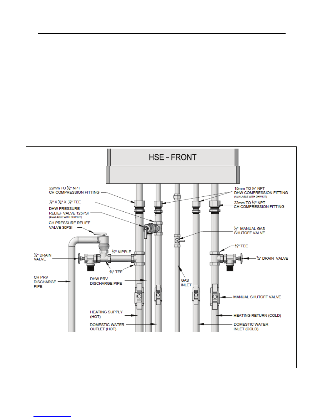
1.4.1.1 CH PIPING CONNECTIONS (Refer to Figure 7)
1. Use the compression fittings supplied with the appliance to connect the heating system
supply and return pipes. Check whether the compression rings are straight in the connectors.
All pipes must be installed tension-free in order to avoid ticking of the pipes. The connections
must not be twisted in order to avoid leaks at the joint points.
2. The CH system is recommended with:
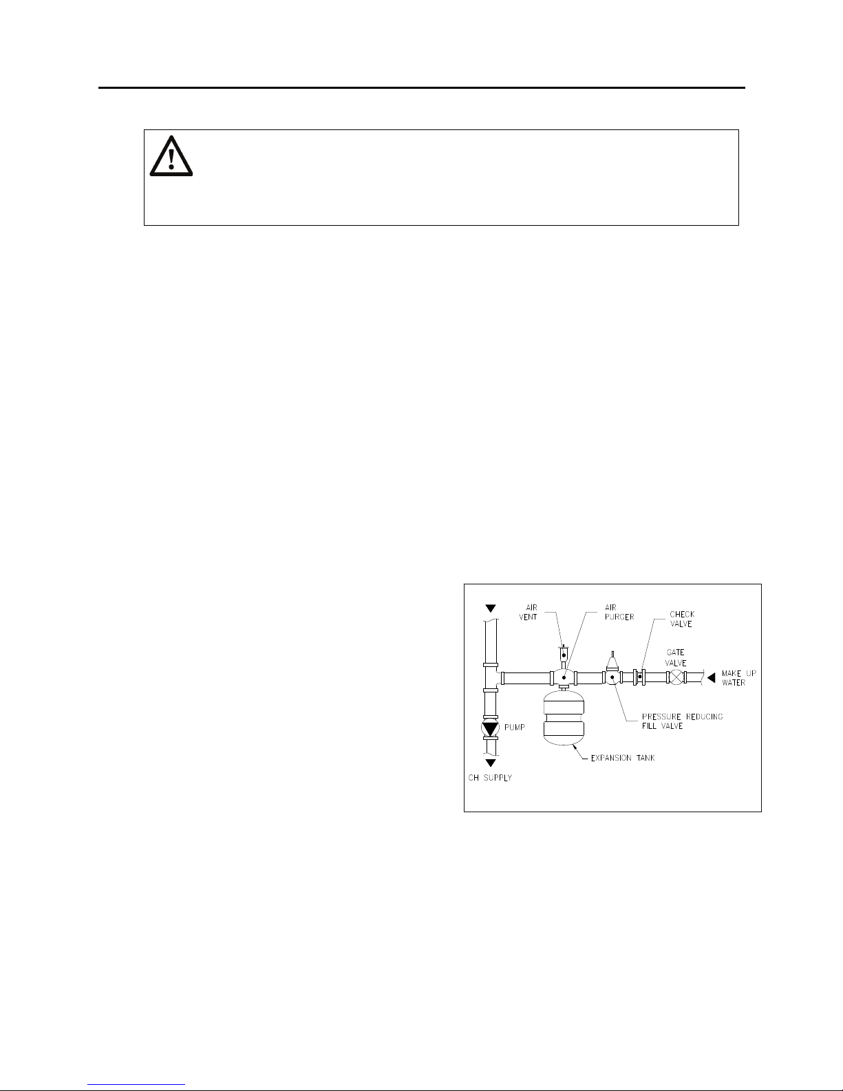
• A make up water loop in the system below the appliance as shown in figure 8.
• A drain tap at the lowest point of the system.
• An expansion tank (Follow section 1.4.1.4).
• A check valve when pipes are running upward at a short distance from the appliance.
This prevents gravity circulation during domestic hot water operation of the appliance.
3. Flush the CH system thoroughly after finishing the piping installation and purge trapped air.
Note: Install pressure relief valve 6" [153mm] below the bottom of the appliance casing to allow for controller opening.
Figure 7 Piping system installation
15
HSE Installation and Service Manual
1.4.1.2 PRESSURE RELIEF VALVE
WARNING
The pressure relief valve discharges pressurized hot water which can turn into steam.
Steam exiting the discharge outlet can explosively expand in all directions. Always
maintain a safe distance from the discharge pipe outlet in order to avoid potential
contact with exiting hot water or steam and injury.
A pressure relief valve is supplied as standard equipment. The pressure relief valve is extra
protection against damage that could be caused by malfunctioning controls or excessive water
pressure. The pressure relief valve is a code requirement. Field installation of the relief valve
must be consistent with the ANSI/ASME Boiler and Pressure Vessel Code, Section IV. The
manufacturer is not responsible for any water damage. If a pressure relief valve is not used, the
warranty is void.
The pressure relief valve should be installed on the boiler outlet with its spindle vertical. The
connection between the boiler and the relief valve must have at least the area of the relief valve
inlet. No valve should be installed between the pressure relief valve and the appliance or in the
discharge piping.
A discharge pipe should be used. The discharge pipe outlet should be positioned over a suitable
drain and so arranged that there will be no danger of being scalded. The discharge pipe must
pitch down from the valve and should be no smaller than the outlet of the valve. The end of the
discharge pipe should not be concealed or threaded and should be protected from freezing.
Extensive runs, traps or bends could reduce the capacity of the pressure relief valve.
1.4.1.3 MANUAL SHUTOFF VALVES (Refer to Figure 7)
Install the manual shut off valves on the supply and return pipes.
1.4.1.4 EXPANSION TANK AND MAKE-UP WATER
The boiler requires an expansion tank which is of
the adequate volume for the heating system. For
larger volume systems, an additional expansion
tank may be required. Consult heating system
engineer and the expansion tank manufacturer
for proper sizing information.
Install make-up water connections as per local
codes. If a pressure reducing valve is used as
shown in figure 8, adjust it to match the system
fill pressure. Also adjust the diaphragm type
expansion tank air pressure to match the system
fill pressure. In connecting the cold make-up
water supply to the appliance, make sure that
clean water supply is available. When the water
supply is from a well or pump, a sand strainer
should be installed at the pump.
1.4.1.5 SYSTEM BYPASS AND PRESSURE HEAD LOSSES
A bypass (primary/secondary piping) is not required for the safe operation of the appliance. It
may, however, be required in conjunction with certain controls on a heating system.
Figure 8 Example of make up water loop
Pump head and pressure drop of the CH heat exchanger versus water flow rate are shown in
Figure 30. To confirm if the equipped pump meets the system pressure drop or requires an
additional system pump, the system pressure drop must be calculated by a qualified heating
system designer.
16
HSE Installation and Service Manual
1.4.1.6 CORROSION PREVENTION (Internal)
The use of oxygen barrier tubing is recommended to protect the system and its components (e.g. pump)
from corrosion. Should your system include "non-oxygen barrier” tubing please contact the factory or a
heating professional for recommendations.
If freeze protection is required, use an inhibited propylene glycol solution which is specifically designed
for hydronic heating systems and always maintained at a neutral pH (e.g. Fernox Alphi-11 or equivalent).
Follow the supplier’s instructions for proper use and maintenance. Do not use automotive antifreeze.
Some types of chemical additives can cause problems (e.g. accelerated corrosion, reduced efficiency,
etc.) and could result in premature failure of the boiler heat exchanger and/or system components,
especially when not properly used or maintained. Corrosion is a preventable condition and is not covered
by the product warranty.
1.4.2 DHW PIPING SYSTEM (WATER HEATER)
The appliance includes standard parts for connection to a central heating (CH) system. For
connection to domestic hot water heating (DHW) system, the DHW kit must be used with the
appliance and can be supplied upon request.
1.4.2.1 DHW PIPING CONNECTIONS
1. Piping and components connected to the water heater shall be suitable for use with potable
water.
2. Flush the hot and cold water system thoroughly to clean out metal powder, sand and dirt
before connecting it.
3. Use compression fittings supplied to connect the DHW supply and return pipes (refer to
Figure 7). Check whether the compression rings are straight in the connectors. All pipes must
be installed tension-free in order to avoid ticking of the pipes. The connections must not be
twisted in order to avoid leaks at the joint points.
4. Test that there are no water leaks from the cold and hot water supply pipes and then insulate
all water piping especially the hot supply and recirculation water lines, and cold water pipe
according to the climate of the region or local code to prevent the pipe from freezing. Do not
cover the drain or pressure relief valve.
WARNING
Potential Scald Hazard. A thermostatic mixing valve must be used to prevent potential scalding
hazards that may result in severe personal injury or death.
When the appliance is used for hot water supply
only in the summer, the CH heating function can
be switched off with the service code on the
operating panel.
If the appliance is shutdown during the winter,
the domestic hot water and heating water loops
should be drained to prevent the pipes from
freezing. Also disconnect the make up water for
the CH heating loop and cold water for the
domestic hot water at the bottom of the
appliance.
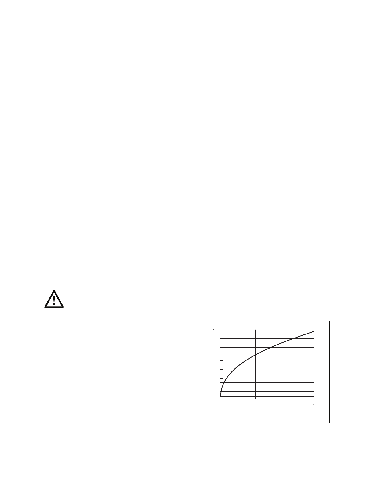
Figure 9 shows the domestic hot water flow rate
versus the cold water pressure ± 10%.
17
(l/min)(gpm)
15
4.0
13
3.4
11
2.9
9
2.4
7
1.9
5
1.3
3
0.8
1
0.3
Y
0 0.2 0.4 0.6 0.8 1.0 1.2 1.4 1.6 1.8 2.0 (bar)
X
2.9 5.8 8.7 11.6 14.5 17.4 20.3 23.2 26.1 29.0 (psi)
Figure 9 DHW flow rate vs. water pressure

HSE Installation and Service Manual
1.4.2.2 DHW PIPING WITH A BACKFLOW PREVENTER
If the water heater is installed in a closed water supply system, such as one having a backflow
preventer in the cold water supply line, means shall be provided to control thermal expansion.
Contact the water supplier or local plumbing inspector on how to control this situation.
1.4.2.3 PRESSURE RELIEF VALVE OR TEMPERATURE AND PRESSURE RELIEF VALVE
A pressure relief valve must be installed near the domestic hot water outlet. If the unit is
connected to a separate storage vessel, the separate vessel must have its own temperature and
pressure relief valve. The pressure relief valve or temperature and pressure relief valve must be
rated in accordance with and comply with the Standard for Relief Valves for Hot Water Supply
Systems, ANSI Z21.22/CSA 4.4 or the ANSI/ASME Boiler and Pressure Vessel Code, Section IV
(“Heating Boilers”).
The location of the relief valve shall be accessible for servicing or replacement. If a separate
storage vessel is installed, it shall have a tapping separate from the tapping for the water
connections to accommodate a temperature and pressure relief valve of adequate size to protect
the water heater. This tapping shall be clearly identified on Class III marking material and shall
be located in the top of the tank, or in the side of the tank on a centreline within the upper 6
inches of the top of the tank. The tapping shall be threaded in accordance with the Standard for
Pipe Threads, General Purpose (Inch), ANSI/ASME B1.20.1.
The maximum Btu/h discharge capacity of the pressure relief valve must be at least equal to the
maximum input rating of the water heater. The maximum relieving pressure setting must not
exceed 150 psi (10.3 bar). No valve shall be placed between the relief valve and the water
heater, relief valve and the storage tank, or in the discharge pipe as shown in figure 7.
Avoid contact with the hot water and steam discharged to prevent personal injury. The discharge
pipe outlet should be positioned over a suitable drain within 6” (152 mm) from the floor. It must
be arranged so that there will be no danger of being scalded and the hot water cannot splash on
anyone or nearby equipment.
The discharge pipe must pitch down from the valve and should be no smaller than the outlet of
the valve. The end of the discharge pipe should not be concealed or threaded and should be
protected from freezing. Extensive runs, traps or bends could reduce the capacity of the pressure
relief valve. No reducing coupling or other restriction can be installed in the discharge line.
If a relief valve discharges periodically, this may be due to thermal expansion in a close water
supply system. Contact the water supplier or local plumbing inspector on how to correct this
situation. Do not plug the relief valve.
1.4.2.4 CATHODIC PROTECTION DEVICES
When cathodic protection devices are used in the storage tank, hydrogen gas can be produced in
a hot water system that has not been used for a long period of time (generally two weeks or
more). Hydrogen gas is extremely flammable. To prevent the possibility of injury under these
conditions, we recommend the hot water faucet be open for several minutes at the kitchen sink
before you use any electrical appliance which is connected to the hot water system. If hydrogen
is present, there will probably be an unusual sound as air escaping through the pipe as the hot
water begins to flow. There should be no smoking or open flame near the faucet when it is open.
1.4.3 APPLIANCE USED WITH SOLAR SYSTEMS
This appliance is suitable for use with solar hot water systems and can be buffered using a Super
Hot storage tank or indirect hot water tank. Contact Allied Engineering Company for details.
1.5 GAS SERVICE PIPING
All piping and fittings must be installed as per codes in Section 1.2. Make sure the gas on which the
appliance will operate is the same as that specified on the appliance rating plate. Do not install the
appliance if equipped for a different type gas. Consult your gas supplier to get gas information.
18

HSE Installation and Service Manual
To prevent damage, care must be taken not to apply too much torque when connecting pipe fitting of gas
supply to gas inlet pipe on the appliance. A manual main shut-off valve must be installed in the gas line
outside the appliance jacket and as required in Section 1.2. The valve should be readily accessible for
turning on and off.
When a vertical section of gas piping is supplied on the upstream side of the gas controls, a drip pocket
or sediment trap must be installed at the inlet of gas connection to the appliance (in the gas supply line
upstream of the gas controls and as close to the appliance as possible), example shown in Figure 10.
The appliance and its gas connection must be leak tested before
placing the appliance in operation. The gas controls furnished
are suitable for a maximum operating gas pressure of 1/2 psi (14
inches water column/356 mm water column).
The appliance and its individual shutoff valve must be
disconnected from the gas supply piping system during any
pressure testing of that system at test pressures in excess
psig (14 inches water column/356 mm water column).
The appliance must be isolated from the gas supply piping
system by closing its individual manual shutoff valve during any
pressure testing at test pressures equal to or less than
(14 in. water column/356 mm water column).
The pipe compound used should be resistant to the action of liquefied petroleum gases. Check for gas
leaks in piping, connection to appliance, and gas valve inlet before placing the appliance in operation by
using a soap and water solution. Also check for gas leaks at the gas valve outlet when the appliance is
on. DO NOT USE AN OPEN FLAME.
of 1/2
1/2 psig
Figure 10 Sediment trap for gas line
INSTALLER MUST IDENTIFY EMERGENCY SHUT-OFF DEVICES.
1.6 ELECTRICAL CONNECTION
WARNING Electrical shock hazard can cause severe injury or death. Disconnect power before
installing or servicing.
The appliance requires a 120 Vac 60 Hz power supply, and must be grounded. All electrical
connections must be made in full accordance with the Code requirements listed in Section 1.2.
WARNING Label all wires prior to disconnection when servicing controls. Wiring errors can
cause improper and dangerous operation. Verify proper operation after servicing.
Run a separate electrical circuit from the electrical service panel through a fused disconnect switch to the
appliance. This appliance must be electrically bonded to ground in accordance with the requirements of
the authority having jurisdiction (local codes) or, in the absence of such requirements, with the National
Electrical Code, ANSI/NFPA 70 (current edition) and/or the Canadian Electrical Code, CSA C22.1 Part 1
(current edition). Field wiring shall conform to Section 2.2 and to the temperature limitations of Type T
[63°F (35°C) rise or better.
Make wiring connections as follows:
1. Unscrew the screws (A) in order to gain access to the space of the
appliance controller (B). Refer to Figure 11.
2. The cover plate (display) hinges open downwards to access to the
controller and electrical connections.
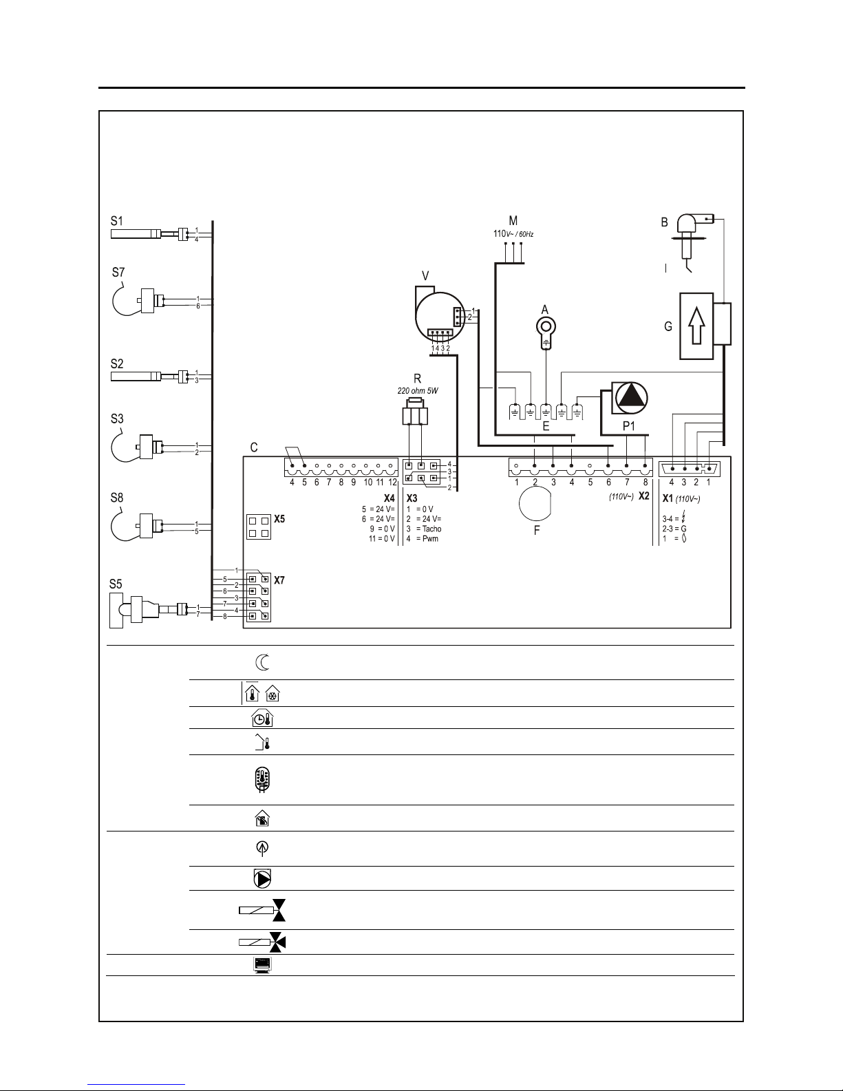
3. Refer to electrical wiring diagram in Figure 12 to make the electrical
connections.
4. After making the required connections, replace the appliance
controller.
Figure 11 Open control panel
19
HSE Installation and Service Manual
A Ground terminal heat exchanger F Fuse (3.15A T) P1 CH pump S3 DHW sensor
B Cable of ignition/flame sensor G Gas valve R Resistor S5 Flow switch DHW
C Burner controller I Ionisation/Ignition probe S1 CH Flow sensor S7 High limit
E Ground terminals burner controller M Power supply S2 CH Return sensor
V Blower
S8 Flue sensor
Connector X4
24V =
6-7
6-7-9
8-9
9-10
11-12
Connector X2
~
115V
7-8
3-5-6
Connector X5
4-5
2-4
3-5-6
External economy switch (When using DHW comfort function “Eco” or “On”, 4 and 5 must
be closed)
On/off room thermostat 0.1A 24V= and/or Frost thermostat.
Power supply clock thermostat (6=positive, 7=switched live, 9=negative) 24V= max.3VA
Outdoor sensor 12kOhm/25°C
Tank Thermostat for indirect hot water tank
- Installer parameter 1 must be set to 1. Installer parameter n must be set.
- DHW sensor S3 must be disconnected.
OpenTherm (When in use, 6-7 must be open)
Power supply (2=Live, 4=Neutral)
CH pump (8=Live, 7=Neutral)
Valve floor heating (3=Live, 5=Switch live, 6=Neutral) (VC4011 Honeywell 115V~)
Three way valve (3=Live, 5=Switch live, 6=Neutral) (VC4011 Honeywell 115V~)
PC interface
Figure 12 Control Wiring Diagram
20

HSE Installation and Service Manual
1.7 VENTING AND COMBUSTION AIR
DEFINITIONS
A direct vent (a balanced flue) appliance – an appliance that operates with all air for combustion
obtained from the outdoor atmosphere and all flue gases discharged to the outdoor atmosphere.
A non-direct vent appliance – an appliance that operates with all air for combustion obtained from the
boiler room and all flue gases discharged to the outdoor atmosphere.
This appliance is certified as a direct vent appliance only. The venting system must be installed in
accordance with this manual and the venting manufacturer’s certified installation instructions.
Provision for combustion and ventilation air must be met in accordance with Chapter 5.3, Air for
Combustion and Ventilation and Chapter 7, Venting of Equipment, of the National Fuel Gas Code, ANSI
Z223.1/NFPA 54 in USA, and Section 7, Venting Systems and Air Supply for Appliances, of the Natural
Gas and Propane Installation Code, CAN/CSA B149.1 in Canada. Also, applicable provisions of the local
building codes must be followed. Contact local building or fire officials about restrictions and installation
inspection in your area. If there is any conflict in the above Code requirements, the more stringent
requirement applies.
For a direct vent appliance installation, sufficient air for ventilation in the appliance room or closet should
be provided from indoors to reduce the room air temperature.
The air supply and venting terminations must always be kept clear of obstructions (i.e. snow, ice, etc.).
The responsibility of providing a suitable venting and air intake tube of adequate draft capacity and in
good usable condition is that of the gas fitter/installer. Interference with the air supply for the appliance
shall be prohibited.
Removal of an Existing Boiler
When an existing appliance is removed from a common venting system, the common venting system is
likely to be too large for proper venting of the appliances connected to it.
At the time of removal of an existing appliance, the following steps shall be followed with each appliance
remaining connected to the common venting system placed in operation, while the other appliances
remaining connected to the common venting system are not in operation.
a) Seal any unused openings in the common venting system.
b) Visually inspect the venting system for proper size and horizontal pitch and determine there is no
blockage or restriction, leakage, corrosion and other deficiencies which could cause an unsafe
condition.
c) Insofar as is practical, close all building doors and windows and all doors between the space in which
the appliances remaining connected to the common venting system are located and other spaces of
the building. Turn on clothes dryers and any appliance not connected to the common venting
system. Turn on any exhaust fans, such as range hoods and bathroom exhausts, so they will
operate at maximum speed. Do not operate a summer exhaust fan. Close fireplace dampers.
d) Place in operation the boiler being inspected. Follow the lighting instructions. Adjust the thermostat
so the appliance will operate continuously.
e) Test for spillage at the draft hood relief opening after 5 minutes of main burner operation. Use the
flame of a match or candle, or smoke from a cigarette, cigar or pipe.
f) After it has been determined that each appliance remaining connected to the common venting system
properly vents when tested as outlined above, return doors, windows, exhaust fans, fireplace
dampers and any other gas burning appliance to their previous conditions of use.
g) Any improper operation of the common venting system should be corrected so the installation
conforms with the National Fuel Gas Code, ANSI Z223.1 and/or the Natural Gas and Propane
21

HSE Installation and Service Manual
Installation Code, CAN/CSA B149.1. When re-sizing any portion of the common venting system, the
common venting system should be resized to approach the minimum size as determined using the
appropriate tables in Part 11 of the National Fuel Gas Code, ANSI Z223.1/NFPA 54 and/or the
Natural Gas and Propane Installation Code, CAN/CSA B149.1.
1.7.1 CORROSIVE ATMOSPHERE
If the appliance is to be installed near a corrosive or potentially corrosive air supply, the appliance
must be isolated from it and outside air must be supplied as a direct venting system.
Chemical vapors from products containing chlorine or fluorine must be avoided. Even though
these chemicals may be safe to breathe, corrosive substances can become liberated when
passed through a gas flame. Even at low concentrations, these chemicals can significantly
contaminate the air supply and shorten the life of any gas-fired appliance. The following is a list of
some of the products which should be avoided:
• bleaches and chlorinated cleaning products
• paints and sprays
• water softeners (calcium or sodium chloride)
• leaking refrigeration equipment
• Freon from common aerosol dispensers
These chemicals are especially common near swimming pools, beauty shops, dry cleaning
establishments, laundry areas, workshops, and garages. The warranty is void when failure is
due to corrosion.
1.7.2 AIR INTAKE SYSTEM
For a direct vent system, DWV (drains, waste, vents) PVC, CPVC, ABS, galvanized steel tube,
and flex aluminum tube can be used for the air intake system. Do not use these materials for the
exhaust vent system. ULC S636 PVC and CPVC or stainless steel tube may also be used for the
air intake system. The air intake tube and its joints should be sealed using appropriate sealants
when necessary.
1.7.3 EXHAUST VENT SYSTEM
WARNING
Failure to comply with these instructions may result in a failure of venting system and
leakage of flue products to the living space. Only certified
may be used to vent this appliance. Do not use cellular core for vent piping. Follow
vent manufacturer’s recommendations for vent installation.
WARNING
Venting and components (e.g. elbows, primer, cement) are to be installed as a system
as per the vent manufacturer’s installation instructions. Do not mix and match
components from different vent systems.
This appliance will produce some condensate with a positive vent static pressure during
operation and therefore an air-tight and anti-corrosion venting system must be used. Use only
certified PP, CPVC or stainless steel exhaust venting which has been approved. The following
manufacturers offer venting and components approved for use with this appliance:
PP, CPVC or stainless steel
CPVC schedule 40 venting tube and components:
• In Canada, IPEX: System CPVC or certified type of ULC S636
• In USA, ANSI/ASTM F441, CPVC schedule 40 or certified type
22

HSE Installation and Service Manual
PP venting tube and components:
• In Canada, M&G: PP system, certified type of ULC S636
• In USA, ANSI/ASTM, PP system, certified type
Stainless steel venting tube and components (certified types for Category IV):
• Flexmaster Canada Ltd.: Z-Vent
• Z-Flex U.S., Inc.: Z-Vent
• Heat-Fab Inc.: Saf-T-Vent
• Flex-L International Inc.: StaR-34
• Protech Systems, Inc.: FasNSeal
The use of these manufacturers' venting systems for sidewall venting will require the use of a
vent terminal specified by Allied Engineering Company. The vent terminal for a vertical venting
system should be obtained from the supplier of the venting system listed above.
1.7.4 VENT TERMINAL INFORMATION
The minimum distance from the vent terminal to adjacent public walkways, adjacent buildings,
operable windows and building openings shall be not less than those values specified in the
National Fuel Gas Code, ANSI Z223.1/NFPA 54 and/or the Natural Gas and Propane Installation
Code, CAN/CSA B149.1.
TM
Flue gas condensate can freeze on the exterior walls or on the vent termination. Frozen
condensate on the vent cap can result in a blocked flue condition and should be removed to keep
the appliance operating normally.
Some discoloration to exterior building surfaces can be expected. Adjacent brick or masonry
surfaces should be protected with a rust resistant sheet metal plate. To prevent discoloration and
degradation of building materials by flue gases and flue gas condensation, ensure that the vent
terminal is installed clear of nearby obstacles. In all cases, installation shall be in accordance with
applicable code(s).
For proper operation, the vent terminal must be kept free of snow, leaf dropping and other debris
at all times to ensure that no blockage occurs.
Do not terminate the vent in a window well, stairwell, alcove, courtyard, or other recessed area.
The vent cannot terminate below grade and over paved walkways or paved driveway that is
located between two single-family dwellings and serves both dwellings, or near soffit vents or
crawl space vents or other area where condensate or vapor could create a nuisance or hazard or
cause property damage; or where condensate or vapor could cause damage or could be
detrimental to the operation of regulators, relief valves, or other equipment. The vent shall not
terminate underneath a veranda, porch, or deck unless the veranda, porch, or deck is fully open
on a minimum of two sides beneath the floor and the distance between the top of the vent
termination and the underside of the veranda, porch, or deck is greater than 1 foot (300 mm).
Do not locate the vent terminal directly under roof or deck overhangs to prevent icicles from
forming. Due to the low flue gas temperature, ‘pluming’ will occur at the flue terminal. Care
should be taken to ensure that the discharge plume will not cause annoyance to the neighbors.
Therefore, never allow vent terminal towards neighbor’s windows or where personal injury or
property damage can occur.
The terminal shall not be installed in any area which is not allocated to the occupancy in which
the appliance is installed.
In a structure with three walls and a roof, the terminal shall not be installed:
23

HSE Installation and Service Manual
a) more than 72 inches (1.8 m) from the outside opening;
b) on any wall that has an opening between the terminal and the open side of the structure.
It is highly recommended that the vent terminal be located where it will not be exposed to normal
prevailing winds.
The vertical termination shall extend to the required height above the highest point where it
passes through the roof of the building and located higher than any portion of a building within a
horizontal distance of the required distance, or specified as local jurisdiction.
The vent terminal shall be located at a certain distance from any building opening and above any
mechanical air supply inlet to any building.
Gas service meters:
The vent shall not terminate within 3 feet (0.9 m) of any gas service regulator
vent outlet and mechanical air inlet to building requires a clearance of 10 feet (3.0 m) from any
gas service regulator internal relief vent. Vents are prohibited above the gas meter assembly
(not propane regulator vents) within 3 feet (0.9 m) horizontally of the vertical center line of the
regulator to a vertical distance of 15 feet (4.6 m).
The bottom of the vent terminal and the air intake shall be located at least 12 inches (0.3 m)
above grade plus height of the normal snow line.
The terminal shall not be less than 7 feet (2.1 m) above grade where located adjacent to a public
walkway and shall not terminate over public walkways or over an area where condensate or
vapor could create a nuisance of hazard or could be detrimental to the operation of regulators,
relief valves, or other equipment.
The diagram as shown in Figure 13 indicates vent terminal clearances A to M for a direct vent
appliance. The clearance marked on the diagram are stated separately in Table 2 for US and
Canadian installations and shall not be less than those specified in the current ANSI
Z223.1/NFPA 54 National Fuel Gas Code or CSA-B149.1, Natural Gas and Propane Installation
Codes, as applicable. For clearances not specified in ANSI Z223.1/NFPA 54 or CSA-B149.1, the
clearances shall be in accordance with local installation codes and the requirements of the gas
supplier.
Figure 13 Direct Vent Terminal Clearances
24

HSE Installation and Service Manual
Table 2 Direct Vent Terminal Clearances (Refer to Figure 13)
Canadian Installations
A= Clearance above grade,
12 inches (30 cm) 12 inches (30 cm)
1
US Installations2
veranda, porch, deck, or
balcony
B= Clearance to window or door
that may be opened
C= Clearance to window or door
that may be opened
D= Clearance to permanently
closed window
E= Clearance to unventilated
soffit
6 inches (15 cm) for appliances ≤
10,000 Btuh (3 kW), 12 inches
(30 cm) for appliances > 10,000
Btuh (3 kW) and ≤ 100,000 Btuh
(30 kW), 36 inches (91 cm) for
appliances >100,000 Btuh (30
kW)
* *
* *
* *
6 inches (15 cm) for appliances ≤
10,000 Btuh (3 kW), 9 inches (23
cm) for appliances > 10,000 Btuh
(3 kW) and ≤ 50,000 Btuh (15
kW), 12 inches (30 cm) for
appliances > 50,000 Btuh (15
kW)
F= Clearance to outside corner * *
G= Clearance to inside corner * *
H= Clearance to each side of
center line extended above
meter/regulator assembly
I= Clearance to service
regulator vent outlet
J= Clearance to non-mechanical
air supply inlet to building or
the combustion air inlet to any
other appliance
K= Clearance to a mechanical air
supply inlet
3 feet (91 cm) within a height 15
feet above the meter/regulator
*
assembly
3 feet (1.83 m)
6 inches (15 cm) for appliances ≤
10,000 Btuh (3 kW), 12 inches
(30 cm) for appliances > 10,000
Btuh (3 kW) and ≤ 100,000 Btuh
(30 kW), 36 inches (91 cm) for
appliances >100,000 Btuh (30
kW)
6 inches (15 cm) for appliances ≤
10,000 Btuh (3 kW), 9 inches (23
cm) for appliances > 10,000 Btuh
(3 kW) and ≤ 50,000 Btuh (15
kW), 12 inches (30 cm) for
appliances > 50,000 Btuh (15
kW)
*
6 feet (1.83 m) 3 feet (91 cm) above if within 10
feet (3 m) horizontally
L= Clearance above paved
sidewalk or paved driveway
7 feet (2.13 m) †
*
located on public property
M= Clearance under veranda,
porch deck, or balcony
1
In accordance with the current CSA B149.1 Natural Gas and Propane Installation Code
2
In accordance with the current ANSI Z223.1 / NFPA 54 National Fuel Gas Code
12 inches (30 cm) ‡
*
† A vent shall not terminate directly above a sidewalk or paved driveway that is located between two
single family dwellings and serves both dwellings.
‡ Permitted only if veranda, porch, deck, or balcony is fully open on a minimum of two sides beneath
the floor.
* For clearances not specified in ANSI Z223.1 / NFPA 54 or CSA-B149.1, one of the following shall
be indicated:
a) A minimum clearance value determined by testing, or;
b) A reference to the following footnote:
“Clearance in accordance with local installation codes and the requirements of the gas supplier.”
25
HSE Installation and Service Manual
1.7.5 DIRECT VENT CONFIGURATIONS
WARNING
Failure to ensure that tubes are connected, seated or sealed properly may result in leakage and
eventual failure of the sealing gasket.
Five venting configurations are available for the appliance:
Twin Tube
• 3 inch CPVC twin tube venting system with 80 mm to 3 inch CPVC adapters
• 3 inch stainless steel twin tube venting system with 80 mm to 3 inch stainless steel adapters
• 80 mm PP twin tube venting system, adapter not required
Concentric
• 80 mm/125 mm PP concentric venting system with a concentric adapter
Combination
• 80 mm PP twin tube venting joined to 80 mm/125 mm PP concentric venting system using a twin
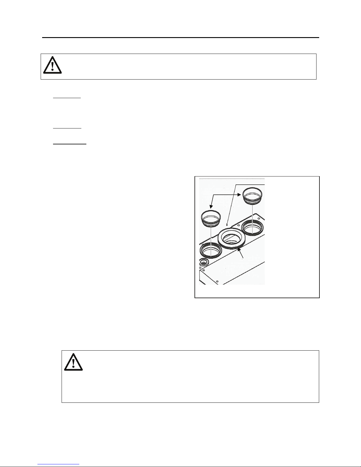
1.7.5.1 TWIN TUBE TO APPLIANCE CONNECTION (Refer Figure 14)
tube to concentric adapter
1. Right-hand air supply is for standard
installation. The sealing cap must be removed,
if there is one.
2. Install the tubes or adapters (if required) into
air supply opening and the flue collar on the top
of the appliance. The built in sealing rings
provide airtight connections. The joints of air
supply tubes should be sealed by silicone or
other means. The flue tubes should be sealed
following flue tube supplier’s installation
instructions.
1.7.5.2 CONCENTRIC TO APPLIANCE
CONNECTION (Refer to Figure 15)
1. Properly seal the air supply opening on the
appliance with the sealing cap supplied with the
set (item B in Figure 14)
Figure 14 Air supply and flue openings
2. Replace the existing sealing ring (item A) on
the top of the appliance, as shown in Figure 14, by the sealing ring ø 116 x 110 mm (4.6 in x 4.33
in) which should be provided by manufacturer.
3. Fit the adapter on the flue discharge.
4. The venting tubes should be sealed following venting tube supplier’s installation instruction.
CAUTION:
In Canada, follow CAN/CSA B149.1 (current edition) and/or local code
requirements for use of plastic venting
B
A
Replace this sealing
ring by 116x110mm
(4.6x4.3”) sealing
ring for concentric
connection
Plastic vents shall be installed such that the first 3 feet (92 cm), or total vent run if less
than 3 feet (92 cm) from the appliance flue outlet, is readily accessible for visual
inspection. (CAN/CSA B149.1, clause 8.9.5)
26

HSE Installation and Service Manual
1.7.6 EQUIVALENT VENT/AIR INTAKE TUBE LENGTH AND DIAMETERS
The resistance of the combustion air supply and the flue gas tubes depends on the length, the diameter,
components used and venting configuration of the venting system. For the appliance to operate
normally, the venting system, including air intake piping, flue tube and terminal, must not be overly
restrictive. Use Table 3 to determine the venting system equivalent length for a specified vent
configuration. The equivalent venting system length of your installation must be within the maximum and
minimum allowable length specified in Table 3. Use the notes in Table 3 to calculate your venting
systems equivalent length in feet based on the total centerline length and number of elbows for air supply
piping and exhaust vent.
Table 3 Equivalent Venting System Length for HSE-125
MODEL
Direct Vent: Twin Tubes
Equivalent Length of Air and Flue
Tubes in Feet/m
3” diameter
(80mm)
(vertical runs)
3” diameter
(80mm)
(horizontal runs)
Direct Vent: Concentric Tubes
Equivalent Length of Air and Flue
Tubes in Feet/m
3”/5” diameter
(80mm/125mm)
(vertical runs)
3”/5” diameter
(80mm/125mm)
(horizontal runs)
Min. Max. Min. Max. Min. Max. Min. Max.
AIR TUBE
FLUE TUBE
5 ft/
1.52 m
5 ft/
1.52 m
85 ft/
26 m
85 ft/
26 m
5 ft/
1.52 m
5 ft/
1.52 m
85 ft/
26 m
85 ft/
26 m
5 ft/
1.52 m
5 ft/
1.52 m
85 ft/
26 m
85 ft/
26 m
5 ft/
1.52 m
5 ft/
1.52 m
85 ft/
26 m
85 ft/
26 m
NOTES: 1. Choose the right appliance vent outlet adapter (if required) for plastic or stainless
steel vent tube for twin tube or concentric tube venting.
2. Reduce the equivalent length by 6.5 feet (2 m) for each 90-degree elbow added
and by 3.5 feet (1.1 m) for each 45-degree elbow for your estimating the equivalent
venting lengths.
3. Always confirm with the selected venting manufacturer for the actual equivalent
length of elbows.
27

HSE Installation and Service Manual
Table 3a Equivalent Venting System Length for HSE-145
MODEL
Direct Vent: Twin Tubes
Equivalent Length of Air and Flue
Tubes in Feet/m
3” diameter
(80mm)
(vertical runs)
3” diameter
(80mm)
(horizontal runs)
Direct Vent: Concentric Tubes
Equivalent Length of Air and Flue
Tubes in Feet/m
3”/5” diameter
(80mm/125mm)
(vertical runs)
3”/5” diameter
(80mm/125mm)
(horizontal runs)
Min. Max. Min. Max. Min. Max. Min. Max.
AIR TUBE
FLUE TUBE
5 ft/
1.52 m
5 ft/
1.52 m
60 ft/
20 m
60 ft/
20 m
5 ft/
1.52 m
5 ft/
1.52 m
60 ft/
20 m
60 ft/
20 m
5 ft/
1.52 m
5 ft/
1.52 m
60 ft/
20 m
60 ft/
20 m
5 ft/
1.52 m
5 ft/
1.52 m
60 ft/
20 m
60 ft/
20 m
NOTES: 1. Choose the right appliance vent outlet adapter (if required) for plastic or stainless
steel vent tube for twin tube or concentric tube venting.
2. Reduce the equivalent length by 6.5 feet (2 m) for each 90-degree elbow added and
by 3.5 feet (1.1 m) for each 45-degree elbow for your estimating the equivalent
venting lengths.
3. Always confirm with the selected venting manufacturer for the actual equivalent
length of elbows.
1.7.7 EXAMPLE OF 3 INCH DIAMETER TWIN TUBE CALCULATION
Table 4 Example Calculation (Refer to Figure 15)
TUBE TYPE TUBE LENGTHS TOTAL TUBE LENGTHS
Flue Tube L1 + L2 + L3 + 2x6.5feet 40 feet (12.2 m)
Air Supply Tube L4 + L5 + L6 + 2x6.5feet 40 feet (12.2 m)
Total Length 80 feet (24.4 m)
1.7.8 EXAMPLE OF 3/5 INCH (80mm/125mm) DIAMETER CONCENTRIC TUBE CALCULATION
With 3 elbows at 90-degree, the maximum straight length of concentric tube that can be used is:
85 feet – 3 x 2 x 6.5 feet = 46 feet (14 m).
28

HSE Installation and Service Manual
1.7.9 VENT INSTALLATIONS
The following installation procedure is a guide for all
vent installations:
1. The appliance must be vented to the outdoors.
Do not install the vent into a common venting
system. The venting system does not require a
vent damper.
2. When the straight flue pipe is over 9.5 feet (3
m), a venting condensate drain and trap should
be installed. The venting condensate drain
should be installed as close to the appliance as
possible and must be equipped with a drain
trap. The drain trap can be formed by attaching
1/2” (13 mm) diameter flexible tubing to the
drain assembly, making a loop of approximately
6” diameter and securing it with a cord or tie
wrap where the tube crosses over itself Do not
squash the tube or over-tighten it, see Figure
15, or use other type of boiler condensate trap.
The loop or condensate trap must then be filled
with water to form a liquid-filled trap. This trap
allows condensate to drain while preventing
exhaust gases from escaping. The condensate
should be discharged as per section 1.3.7.
Venting condensate trap
L5=2 ft [0.5m]
L2=2 ft [0.5m]
L4=20 ft [6 m]
L3=22 ft [7.5m]
3. Always select the venting systems, including the
terminals, approved for use with this type of
appliance.
[1m]
L1= 3 ft
L6=5 ft [1.5m]
4. Follow the vent manufacturer’s instructions or
applicable codes to install the venting system,
proper venting adapters, spacers, thimbles,
caps, roof flashing, storm collar, supports,
terminal(s), etc and support the venting system
so that its weight does not bear on the
Figure 15: Sample of venting length estimate
appliance.
5. Provide minimum service clearance from vent components to the wall as specified in the section
1.3.
6. The vent system has a positive pressure in the flue requiring that all vent joints and seams be
properly cleaned and sealed gas-tight by following the vent manufacturer’s instructions. Also,
seal the joints of tube/storm collar and flashing/storm collar with waterproof caulking for a vertical
venting installation.
7. Increasing the length of the exhaust vent run will increase the amount of condensate. The
condensate of the exhaust is acidic and can cause severe corrosion of ordinary venting
materials. Also, appliance operation can be affected by restrictive vent or combustion air supply
piping. Therefore, venting lengths must be within the specified minimum and maximum
equivalent venting system length in Table 3.
8. Slide the adapters (if required) or air supply and flue tubes into the combustion air intake and flue
outlet of the appliance so that the gaskets seal snugly around the adapter. Ensure that there are
no gaps or leaks.
9. Connect the required combustion air and vent tubes to the adapters (if installed) by following the
vent manufacturer’s instructions and applicable code(s).
29

HSE Installation and Service Manual
10. Generally, all vent tubes must be adequately supported with vent supports no less than five feet
(1.5 m)apart or as per the vent system manufacturer’s instructions or applicable code(s), and at
smaller intervals if necessary to ensure that there are no sagging sections along the horizontal
runs. Do not use the appliance to support the weight of the venting. Noncombustible tube
strap or hangers suitable for the weight can be used to support horizontal runs and maintain vent
location.
11. Horizontal venting tube runs must always be installed with a slope upwards not less than ¼ in/ft
(2 cm/m) from the appliance to the vent terminal. This is to ensure that any condensate in the
venting flows back towards the appliance so that the condensate can be disposed of through the
condensate trap system installed on the bottom of appliance or at the down end of the horizontal
portions of the venting system. This will prevent condensation from gathering in the venting tube
and will also reduce the chance of icicles forming over horizontal tube ends in the winter.
1.7.9.1 HORIZONTAL TWIN TUBE SIDE VENTING WITH TWIN TERMINAL CAPS
Figure 16 is a typical installation for a side venting installation using two 45˚ elbows as twin terminal caps
and adapters (if required) for air inlet and flue outlet on the appliance. A space between the two terminal
caps is required as shown in Figure 16.
Figure 16 Side Venting
1.7.9.2 VERTICAL (ROOF TOP) TWIN TUBE VENTING WITH TWIN TERMINAL CAPS
Figures 17 to 19 are typical installations for the vertical twin tube venting with twin terminal caps and
adapters (if required) for air inlet and flue outlet on the appliance.
Location of the venting terminal has to be determined based on the applicable code before installing the
terminals. Keep the end opening of air terminal at least 12 inches (300 mm) above the normal snow
accumulation that can be expected on the roof and the top of the vent terminal at least 12 inches (300
mm) above the air inlet terminal opening. Support the venting on the outside of the roof if necessary or
based on the code requirements.
Figure 17 Termination Installations adapter on inlet
30

HSE Installation and Service Manual
pply
1.7.9.3 VERTICAL (ROOF TOP) TWIN TUBE VENTING WITH AIR SUPPLY FROM SIDE WALL
A typical installation of a vertical twin tube venting configuration with air supply from side wall is shown in
Figure 20. Install side air supply tube/terminal. The air supply terminal (A) in Figure 20 can be located on
the outside wall.
Location of the venting terminal must be determined based on the applicable code before installing the
terminals.
min. 12”
305mm
min. 12”
305mm
Figure 18 Vertical Twin Tube
Venting
Figure 19 Vertical Twin Tube
Venting
Figure 20 Vertical Single
Venting with Side Air
Su
31

HSE Installation and Service Manual
1.7.9.4 CONCENTRIC CONNECTIONS WITH A COMBINED TERMINAL CAP
CAUTION:
In Canada, follow CAN/CSA B149.1 (current edition) and/or local code
requirements for use of plastic venting
Plastic vents shall be installed such that the first 3 feet (92 cm), or total vent run if less than
3 feet (92 cm) from the appliance flue outlet, is readily accessible for visual inspection.
(CAN/CSA B149.1, clause 8.9.5)
Location of the venting terminal for vertical venting system has to be determined based on the applicable
code before installing the terminals.
Total Concentric Horizontal or Vertical Connection (Figure 21 and 24)
Figures 21 and 24 are typical installations for the total concentric horizontal and vertical venting systems
with a combined terminal cap and a concentric adapter for air inlet and flue outlet on the appliance. The
adapter installation which requires change of the sealing ring referred to in section 1.7.5.2.
Combination Twin Tube and Concentric Connection (Figure 23 and 24)
Figures 22 and 23 are typical installations for combination twin tube to concentric pipe using a twin tube
to concentric adapter and concentric terminal cap.
32

HSE Installation and Service Manual
p
3 deg
above
horiz.
Figure 21 Horizontal Concentric Venting
Figure 23 Vertical Twin Pipe to
Concentric Venting
Max. 27.6” [700mm]
2.0” [50mm]
Ø4.3” [110mm]
Concentric
Pi
e Adapter
Ø4.7” [120mm]
(see note)
8.3”
[210mm]
9.5”
[240mm]
Figure 24 Vertical Concentric Venting
Figure 22 Horizontal Twin Pipe to Concentric
33

HSE Installation and Service Manual
Controller Section 2
2.1 CONTROLLER OPERATION
The appliance uses a microprocessor based controller to manage all functions including ignition and
flame supervision, continuously modulating/monitoring each heat demand from the heating system or
from the domestic hot water supply. The pump starts running when there is a heat demand from the
heating system. The overrun time, which has a default of one minute, can be changed from 0 to 15
minutes if necessary (see setting and adjustment of section 2.4, refer to parameter 8). Also, the controller
will automatically run the pump for 10 seconds once every 24 hours to prevent it from getting seized.
There are two supply temperatures set with a default in the controller memory; one is for Central Heating
(CH) and the other for Domestic Hot Water supply (DHW). If an outdoor temperature sensor is connected
to the appliance, the CH heating supply set point will automatically adjust as the outdoor temperature
changes. For more information about the outdoor reset feature, see the section 2.4.3 and 2.4.6.
The controller modulates the appliance input rate by changing the blower speed based on both the
difference between supply and return temperatures and the set point temperature. The amount of gas
induced into the blower will depend on the blower speed that has been designed to maintain an
approximately constant air-fuel ratio. The minimum input rate is 23% of the maximum input rate. In
addition, all other safety controls including safety high limit and DHW flow switch are connected to the
controller. The controller will shut down the appliance when an unsafe condition exists or, in some cases,
corrects the problem based on the sensor/switch signal.
Step modulation is set on (factory setting) so that the power/speed is increased gradually. This provides
the best CH operation. However, if the appliance is being used for heating an indirect hot water tank, the
step modulation can be set off. The appliance will then start almost immediately at the maximum setting
and the system will heat up faster.
The operating and display panel is shown in Figure 25. The display panel has three primary modes of
operation. These are:
• Standby Mode – displays appliance’s current status. This is the default operating condition.
• Parameter Mode – used to change control settings.
• Information Mode – displays appliance operating temperatures.
The display and operating controls are summarized in Table 5 and operating condition codes are
summarized in Table 6.
34

HSE Installation and Service Manual
7
6
3
1
A
2
B
4
C D
5
E
F
Figure 25 Operating and Display Panel
Table 5 Operating and Display Panel
Display Operating Controls
1. Power On/Off LED
2. CH LED
3. DHW LED
4. Temperature display
5. Fahrenheit LED
7. DHW Eco mode LED
8. DHW Comfort function LED
9. Service display
10. Fault LED
11. CH pressure gauge
A. Power On/Off button
B. CH/HW Temp button
C. - button
D. + button
6. Celsius LED
Notes: An illuminated LED indicates “ON” or active status.
When the red Fault LED (above the Reset button) flashes on, the burner controller has detected a fault. In
the Temperature display (4), a fault code appears.
8
G
10
9
11
H
E. ˚F/˚C button
F. Comfort button
G. Service button
H. Reset button
Table 6 Operating Condition Codes
Operating condition codes (shown in item 9 in Figure 25):
-
Off (frost protection active)
Stand-by
0
Pump overrun
1
Set temperature reached
2
Self-test
3
Blower on
4
Ignition
5
CH operating
6
Domestic hot water operating
7
Comfort function is on or
internal frost protection
The code shown in item 9 in Figure 25 indicates the following operating condition:
- Off
The appliance is not operating, but the power supply is connected to the appliance. There is no response
to any demand for DHW or CH; however, the frost protection is active. If the temperature of the water in
the heat exchanger drops below 41°F (5°C), the pump starts running, the heat exchanger is heated,
code 7 appears on the service display.
Stand-by
After pressing the button of the appliance, the operating condition LED is off. The LED above the
on/off
button is on and if necessary one of the LED’s (item 7 and 8) of the domestic hot water comfort
function is on. The appliance is ready for responding to the demand for CH or DHW.
0 Pump overrun
After the operation of the CH, the pump has an overrun. This overrun time is set at the factory according
to table 8 and may be changed. Also, the controller will automatically run the pump for 10 seconds, once
every 24 hours, to prevent it from getting seized. This activation of the pump takes place at the time of the
last heat demand 24 hours later. In order to change this time, set the room thermostat higher for a while
at the desired time.
35

HSE Installation and Service Manual
1 Set temperature reached
The burner controller can temporarily block the heat demand and stop the burner. This blocking takes
place because the required temperature has been reached. When the temperature has dropped
sufficiently, the blocking is cancelled.
2 Self-test
The burner controller may regularly carry out a self-test and check the connected sensors. During this
time, the controller displays code 2 and does not carry out any other tasks.
3 Blower on
At appliance start-up, the blower is brought to the starting speed. When this speed is reached, the burner
is ignited. Code 3 is also visible during blower post-purge after stopping the burner.
4 Ignition
When the blower has reached the ignition speed, the burner is ignited by means of electric spark ignition.
During ignition, code 4 appears. If the burner is not ignited, another ignition attempt is made after about
5 seconds. If the burner has still not fired after the fourth ignition attempt, the controller indicates a fault.
See section 6.1.
5 CH operation
A room thermostat can be connected to the controller, if necessary, in combination with an outdoor
sensor. See the electric wiring diagram of section 1.6. When heat is demanded by a thermostat signal,
the blower runs (code 3 ) and the burner is ignited (code 4 ), followed by the CH operating condition
(code 5 ).
During CH operation, the blower speed and hence the input rate of the appliance is adjusted. This is done
in such a way that the temperature of the CH water is controlled towards the set CH supply temperature.
In the case of on/off thermostat, the CH supply temperature is set at the operating panel and remains
fixed. In the case of an outdoor sensor, the CH supply temperature will automatically adjust based on the
outdoor air temperature and the outdoor reset function programmed by the user.
The CH supply temperature can be set between 86 °F (30°C) and 194 °F (90°C) and will be displayed on
the operating panel. During CH operating mode, the set CH supply temperature is displayed on the
operating panel, and the actual CH supply temperature can be read by pressing and holding the service
.
key
6 Domestic hot water operation
The hot water supply (HW) has priority over CH heating. When the flow switch detects a domestic hot
water demand of more than 0.53 USGPM (2 l/min), the CH heating demand is interrupted. After starting
the blower (code 3 ) and ignition of the burner (code 4 ), the controller goes to domestic hot water
operation (code 6 ).
During domestic hot water operation, the blower speed and hence the input rate of the appliance is
controlled based on the set domestic hot water temperature. The domestic hot water temperature can be
set between 104 °F (40°C) and 149 °F (65°C). During DHW operating mode, the set domestic hot water
temperature is displayed on the operating panel, and the actual domestic hot water supply temperature
can be read by pressing and holding the service key
.
7 Supply domestic hot water without time delay
For a quick supply of domestic hot water, a comfort function has been provided in the controller. This
function keeps the heat exchanger at the correct temperature. This comfort function is set as per section
2.4.1 c. Code 7 is also displayed when appliance frost protection is active (see code - Off).
36

HSE Installation and Service Manual
2.2 PC INTERFACE
The controller has an interface for a PC. With a special cable and accompanying software, a PC can be
connected. This provision makes it possible to follow the behaviour of the controller, the appliance and
the heating system during a long period.
2.3 TEST PROGRAMS AND FROST PROTECTION
2.3.1 TEST PROGRAMS
In the burner controller, there is a provision for putting
can be done with heat demand on or off.
By activating a test program, the appliance will become active with a fixed blower speed without
intervention of the control functions. The safety functions remain active though.
Simultaneously press
switch off the test program. The test program will automatically switch off after 10 minutes.
Table 7 Test Program
Description of program Press buttons on display
Set burner on with minimum CH input
Set burner on with maximum CH input
Set burner on with maximum DHW input
Switch off test program
2.3.2 FROST PROTECTION
The appliance has provision for protecting its heat exchanger as described below.
NOTE: To avoid the condensate freezing, the appliance must be installed in a FROST-FREE
room.
• In order to avoid appliance (heat exchanger) freezing, an appliance frost
• When the system (or a part thereof) can freeze, a frost thermostat should be
REMARK:
s
protection has been built in. When the temperature of the heat exchanger
drops to 41 ºF (5ºC), the burner will be activated and the pump starts running
until the heat exchanger temperature reaches 50 ºF (10ºC).
Code 7 is given when the appliance frost protection intervenes (heating heat
exchanger).
installed in the area to be protected. Connect this according to the wiring
diagram. See section 1.6.
the appliance into a test status. This test
and on the temperature display of the operating and display panel to
Display reading
panel simultaneously
and
and (1x)
and (2x)
and (or automatically
off after 10 minutes)
“L”
“h”
"H"
Current operating
condition
When the appliance is out of action ( - on the service display), the appliance frost protection is
still active. However, there will be no response to heat demand from an (external) frost
thermostat.
The external frost thermostat is not active when the appliance has been switched off at the
control panel or when the main power supply has been interrupted.
37

HSE Installation and Service Manual
2.4 SETTING AND ADJUSTMENT
The functioning of the appliance is mainly determined by the parameter settings in the controller. User
parameters can be set directly through the operating panel without entering the service code, while the
installer parameters only can be changed by entering the service code.
2.4.1 USER PARAMETER SETTINGS
1. Appliance on/off
The appliance is activated by means of the On/Off
and display panel.
When the appliance is switched on, by pressing the On/Off
(Figure 25, item 1) will be on. When switching the appliance off, by pressing the On/Off
code - is shown on the service display (Figure 25, item 9) to indicate it is still powered.
2. Change the settings of the various functions
a. Change CH supply temperature
Press and hold the CH/HW temp
flashes. Pressing the CH/HW temp
LED should be on. The CH supply temperature can be changed using the
CH supply temperature can be changed between 86 °F (30°C) and 194 °F (90°C).
After completing the change, confirm the change by pressing the Reset
changes are required. If no button is pressed after a period of 30 seconds, the parameter change
menu is closed automatically with any changed settings stored.
Note: If an outdoor reset sensor is connected, the displayed CH temperature is not a set
temperature.
b. Change domestic hot water (DHW) temperature
Press and hold the CH/HW temp
flashes. Pressing the CH/HW temp
LED should be on. The DHW supply temperature can be changed using the
The DHW supply temperature can be changed between 104 °F (40°C) and 149 °F (65°C).
button on the operating panel until the temperature display
button again will switch between CH and DHW; the CH
button on the operating panel until the temperature display
button again will switch between CH and DHW; the DHW
button (Figure 25, item A) on the operating
button, the green Power On/Off LED
button,
and buttons. The
button if no other
and buttons.
After completing the change, confirm the change by pressing the Reset
changes are required. If no button is pressed after a period of 30 seconds, the parameter change
menu is closed automatically with any changed parameters stored.
c. Domestic hot water comfort
The comfort function of domestic hot water can be set by using the Comfort
• Eco (
during the night or after a long absence. The appliance adjusts to the user’s pattern of
domestic hot water use.
• On (
the heat exchanger warm. The appliance always supplies domestic hot water
immediately.
• Off (Both LED's off): The heat exchanger is not kept warm, delaying the supply of hot
domestic hot water. When there is no demand for hot domestic water, the comfort
function can be switched off.
LED on): The comfort function is self-learning. The appliance is deactivated
LED on): The comfort function of the appliance is continuously activated to keep
button if no other
button as follows:
38

HSE Installation and Service Manual
d. Temperature selection (°F/°C)
The temperature selection on the display can be toggled between Fahrenheit and
follows:
• Fahrenheit, °F: Press the ˚F/˚C
Celsius °C LED will turn off.
• Celsius, °C: Press the ˚F/˚C
Fahrenheit °F LED will turn off.
3. Reset button
When a lock out occurs, a figure is flashing on the service display (figure 25, item 9), the appliance
can be restarted by pressing the Reset
fault listed in table 12 of section 6 to determine and resolve the problem before resetting the
appliance.
Note: After 30 seconds of no action, the changes will automatically be stored and the controller will
return to normal.
2.4.2 INSTALLER PARAMETER SETTINGS
The appliance burner controller has been set to the factory default parameters listed in Table
Section 2.4.3.
These parameters can only be changed with the service code. Proceed as follows to activate the
program memory:
1. Switch off the appliance by using the On/Off
2. Simultaneously press the Service and Reset buttons, until a 0 appears on the service
and the temperature displays.
button. The Fahrenheit °F LED will turn on and the
button. The Celsius °C LED will turn on and the
button for 5 seconds. Check the possible cause of the
button ( - on the service display).
Celsius as
8 of
3. Using the
4. Press the Service button to confirm the service code.
5. Use the Service
displayed on the service display).
6. Use the
displayed on the temperature display).
7. Repeat the steps 5 and 6 for other parameters which require change.
8. After making all required changes, press the Reset
display.
9. Switch on the appliance again using the On/Off
The controller has now been reprogrammed.
Notes:
- Pressing the On/Off
you out of the setting menu without storing the parameter changes
- After entering the installer parameter setting, pressing the Service
restore factory parameter settings and ‘F.Set’ will appear on the temperature display.
and buttons, set 15 (service code) on the temperature display.
button to select the parameter to be changed (the parameter will be
and buttons to set the selected parameter to the required value (the value will be
button until P appears on the service
button.
button, before pressing the Reset button to confirm the changes, takes
button for 5 seconds will
39

HSE Installation and Service Manual
2.4.3 SETTING AND DESCRIPTION OF PARAMETERS
The factory default settings and setting ranges for all parameters are shown
in Table 8. The CH
operating input rating can be changed by adjusting the CH input rating % and/or blower speed
following the sections 2.4.2 and 2.4.4.
Table 8 Installer parameters description and default settings for HSE-125
Parameter
(service
display)
0
1 System type 0
2 CH pump continuous 0
3 CH input rating % 99 Setting range: parameter c to 100%
4 HW input rating % 99 Setting range: parameter d to 100%
5
6
7
8
9
A
b Booster 0 n/a
C Modulating option 1
c Minimum input rate CH 30 Setting range 25 to 50%
d Minimum input rate HW 30 Setting range 25 to 50%
E
E. OT response 1
F Ignition blower speed 70 Setting range: 50 to 99%
F.
h
n
o
P
Description
Service code [15]
Min. CH supply temperature
of outdoor reset curve
Min. outdoor temperature of
outdoor reset curve
Max. outdoor temperature of
outdoor reset curve
CH pump off delay time after
CH operation
CH pump off delay time after
external hw tank operation
Three-way or two-way valve
position
Min. supply temperature
during OT demand
(OT = OpenTherm stat)
Ignition blower speed only
DHW
Blower speed for determining
input rating
Set point CH (flow
temperature) during heating
external DHW tank
CH time delay on after DHW
satisfied
Minimum off time after CH
satisfied or boiler off
Default
setting
(temp.
display)
25°C
[77°F]
-7°C
[20°F]
25°C
[77°F]
1 Setting range: 0 - 15 minutes
1 Setting range: 0 - 15 minutes (n/a)
0
40°C
[104°F]
70 Setting range 50 to 99%
47
85°C
[185°F]
0 Setting range: 0 – 15 minutes.
5 Setting range: 0 to 10 minutes (anti cycling function)
Optional Setting of parameter
To access the installer settings by entering the
service code 15.
0 = Standard (CH+DHW operation)
1 = CH operation + Indirect hot water tank
2 = DHW operation only
3 = CH operation only
0 = pump overrun
1 = pump continuously active 2 = n/a
3 = pump on/off with external economy switch
Setting range: 10°C to 25°C [50°F to 77°F]
(Outdoor temperature reset control)
Setting range: -30°C to 10°C [-22°F to 50°F]
(Outdoor temperature reset control)
Setting range: 15°C to 30°C [59°F to 86°F]
(Outdoor temperature reset control)
0 = confirmed during CH operation (n/a)
1 = confirmed during hw operation (n/a)
0 = modulation off during CH operation
1 = modulation on during CH operation
Setting range 10°C to 60°C [50°F to 140°F]. If the OT
thermostat demands a supply temperature that is
below this set value, the heat demand cannot be met.
0 = Ignore OT demand if < value par E
1 = If OT demand < par E then OT demand = par. E
2 = Enable OT
Setting range: 42 to 52 max.
(42 = 4200 rpm, 52 = 5200 rpm).
Setting range: 60°C to 90°C [140°F to 194°F]
40
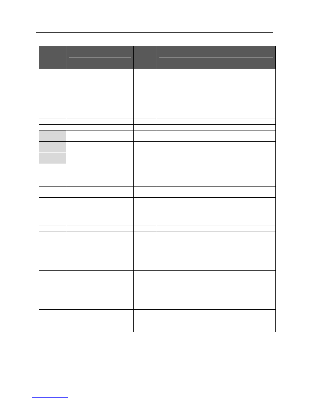
HSE Installation and Service Manual
Table 8a Installer parameters description and default settings for HSE-145
Parameter
(service
display)
0
1 System type 0
2 CH pump continuous 0
3 CH input rating % 99 Setting range: parameter c to 100%
4 HW input rating % 85 Setting range: parameter d to 85%
5
6
7
8
9
A
b Booster 1
C Modulating option 1
c Minimum input rate CH 25 Setting range 20 to 50%
d Minimum input rate HW 25 Setting range 20 to 50%
E
E. OT response 1
F Ignition blower speed CH 40 Setting range: 35 to 85%
F.
h
n
o
P
Description
Service code [15]
Min. CH supply temperature
of outdoor reset curve
Min. outdoor temperature of
outdoor reset curve
Max. outdoor temperature of
outdoor reset curve
CH pump off delay time after
CH operation
CH pump off delay time after
external hw tank operation
Three-way or two-way valve
position
Min. supply temperature
during OT demand
(OT = OpenTherm stat)
Ignition blower speed DHW
only
Blower speed for
determining input rating
Set point CH (flow
temperature) during heating
external DHW tank
CH time delay on after DHW
satisfied
Minimum off time after CH
satisfied or boiler off
Default
setting
(temp.
display)
25°C
[77°F]
-7°C
[20°F]
25°C
[77°F]
1 Setting range: 0 - 15 minutes
1 Setting range: 0 - 15 minutes (n/a)
0
40°C
[104°F]
40 Setting range: 35 to 85%
56
85°C
[185°F]
0 Setting range: 0 – 15 minutes.
5 Setting range: 0 to 10 minutes (anti cycling function)
Optional Setting of parameter
To access the installer settings by entering the
service code 15.
0 = Standard (CH+DHW operation)
1 = CH operation + Indirect hot water tank
2 = DHW operation only
3 = CH operation only
0 = pump overrun only
1 = pump continuously active 2 = n/a
3 = pump on/off with external economy switch
Setting range: 10°C to 25°C [50°F to 77°F]
(Outdoor temperature reset control)
Setting range: -30°C to 10°C [-22°F to 50°F]
(Outdoor temperature reset control)
Setting range: 15°C to 30°C [59°F to 86°F]
(Outdoor temperature reset control)
0 = confirmed during CH operation (n/a)
1 = confirmed during hw operation (n/a)
0 = DHW booster function off
1 = DHW booster function on
0 = modulation off during CH operation
1 = modulation on during CH operation
Setting range 10°C to 60°C [50°F to 140°F]. If the OT
thermostat demands a supply temperature that is
below this set value, the heat demand cannot be met.
0 = Ignore OT demand if < value par E
1 = If OT demand < par E then OT demand = par. E
2 = Enable OT
Setting range: 52 to 60 max.
(52 = 5200 rpm, 60 = 6000 rpm).
Setting range: 60°C to 90°C [140°F to 194°F]
41

HSE Installation and Service Manual
A
2.4.4 SETTING CH & DHW OPERATING INPUT RATING
CH and DHW operating input rating are determined based on the CH
(parameter 3 & 4), blower speed (parameter h) and maximum input rating.
Table 9 CH and DHW operating input rating
CH and DHW input setting
(parameter 3 & 4)
*DHW max 85% for HSE-145
(%)
HSE-145
Input Rate
Btu/h (kW)
HSE-125
Input Rate
Btu/h (kW)
100 145,000 (42.5) 124,000 (36.3)
90 130,500 (38.3) 111,600 (32.7)
80 116,000 (34.0) 99,000 (29.0)
70 101,500 (29.8) 87,000 (25.4)
60 87,000 (25.5) 74,400 (21.8)
50 72,500 (21.3) 62,100 (18.2)
40 58,000 (17.0) 50,000 (14.5)
30 43,500 (12.8) 37,200 (10.9)
23 33,000 (9.7) 28,700 (8.4)
2.4.5 PUMP HEAD AND PRESSURE DROP OF CH H.E.
If the appliance is
equipped with a variable
speed pump, the water flow rate/total
pressure head can be adjusted by turning the
pump switch, as shown in figure 26.
• Set the pump stage based on the
selected CH operating input rating and
pressure drop of the boiler heat
exchanger. Figure 27 shows the
relationship between pressure drop of CH
heat exchanger and/or the total pressure
head of pump and water flow rate through
CH heat exchanger. The type Wilo Star
0 5 10 15 20 25 30 35 40 45
25
20
15
10
Head (feet)
5
S21 with three stages is equipped.
• Measure the temperature difference
between the CH supply and return of the
0
024681012
appliance to ensure that it is about 36°F
(20°C). The table 10 shows an example of
the minimum water flow rate required with
36°F (20°C) temperature rise.
Table 10 CH operating input rating vs. water flow rate
Line A Pressure drop of CH heat exchanger (boiler)
Line I Total pressure head for pump stage 1
Line II Total pressure head for pump stage 2
Line III Total pressure head for pump stage 3
X axis Water flow rate through CH heat exchanger
Y axis Pump pressure head and/or pressure drop of CH H.E.
or DHW input rating %
Figure 26 Pump stage adjustment
Flow (lpm)
Flow (gpm)
7
6
5
4
3
Head (meters)
2
1
0
CH operating input
rating
Min. water flow rate
28,700 BTU/H (8.4 kW) 0.9 GPM (200 l/h)
90,000 BTU/H (26.2 kW) 3.3 GPM (750 l/h)
Figure 27 CH H.E. & Pump head vs. water flow
42

HSE Installation and Service Manual
2.4.6 OUTDOOR RESET FUNCTION
When the outdoor temperature sensor is connected, the
appliance uses the outdoor reset function to control the
CH supply water temperature. Outdoor reset
automatically and continuously adjusts the CH supply
temperature based on the outdoor air temperature
following the reset ratio curve. The reset ratio is
determined from entering the following parameters in the
operating panel:
1. CH supply temperature at minimum outdoor temp
(see section 2.4.1, #2.a)
2. minimum CH supply water
(see Table 8, parameter 5)
3. minimum outdoor temperature
(see Table 8, parameter 6)
4. maximum outdoor temperature
(see Table 8, parameter 7)
Figure 28 shows examples of the outdoor reset curves.
Note: Outdoor Reset Function cannot operate unless an
outdoor temperature sensor is connected. If an outdoor
temperature sensor is not connected, the outdoor reset
function parameters will be ignored and the boiler will
operate at the CH supply temperature setting (as per
section 2.4.1, #2.a)
T supply
°C
°F
194
90
176
80
158
70
140
60
122
50
104
40
86
30
68
20
50
10
32
0
-30 -20 -10 0 10 20 30
Y
X
-22 -4 14 32 50 68 86
A curve: factory default setting
B curve: an example of user setting
X axis – Outdoor temperature
Y axis – CH supply temperature
T max.
A
B
Figure 28 Outdoor reset curve
T min.
T outside
°C
°F
43

HSE Installation and Service Manual
Startup Instructions Section 3
WARNING
If you do not follow these instructions exactly, a fire or explosion may result causing property
damage, personal injury or loss of life.
WARNING
Connect the appliance to the mains voltage only after filling and de-aerating!
WARNING
When an additive is added to the CH water, it must be suitable for use with the materials used
in the appliance and system, such as copper, brass, stainless steel, steel, plastic and rubber.
3.1 CH SYSTEM OPERATING REQUIREMENTS
The CH system is designed for use in closed loop systems. Operating the CH system in an open system
will not result in premature failure of the heat exchanger; however, it will result in premature failure some
of the components which are not anti-corrosion type. Also, avoid unnecessary replenishment of CH
system water. It can allow oxygen to enter the system and cause serious corrosion problems for parts
which are not corrosion resistant. As well, minerals dissolved in a hard water supply will precipitate when
heated and preferentially deposit in the heat exchanger. Therefore, do not draw water from the heating
system for cleaning, flushing, etc.
The HSE is a condensing appliance with forced air combustion and therefore avoids the typical corrosion
and draft problems associated with operating at a low return water temperature. To achieve better
appliance efficiency, the system can be designed with a return water temperature of less than 135°F
(57°C). A lower the return water temperature will result in higher the efficiency, however, ensure that
there is no risk of system water freezing.
THE APPLIANCE MUST ALWAYS BE USED FOR HEATING SYSTEMS WITH FORCED WATER
CIRCULATION.
3.2 PRE-STARTUP
Prefill the condensate trap with water as shown in Figure 30. IMPORTANT: The water must form a liquidfilled trap to prevent exhaust gases from escaping to the
appliance room.
3.2.1 CH SYSTEM
1. Fill entire heating system with water to reach
appliance operating pressure (see section
1.4.1.4) and purge air from appliance using the
manual air vent (A) as shown in Figure 29.
Alternatively, an automatic air vent can be
mounted on the appliance instead of the manual
air vent. Water should be of suitable quality. Do
not use water with high hardness.
2. Check all joints and repair any leaks in water
piping.
3. Check for proper installation of pressure relief
valve and discharge pipe.
Figure 29 Manual air vent
44

HSE Installation and Service Manual
4. Check that the electrical wiring matches the wiring diagram in this manual or on the appliance.
5. Operate circulating pump and vent the system at the highest points of the piping system. Fill the
CH system again if the pressure has dropped too low as a result of the de-aerating.
3.2.2 DHW SYSTEM
1. The DHW system can be connected to a storage hot
water tank. However, do not connect it with an indirect
hot water tank or closed system.
2. De-aerate the heat exchanger and the pipe system by
opening hot water taps. Leave the tap open until all the
air has been released from the system.
2. Check all joints for leaks.
3.2.3 GAS SUPPLY
1. This appliance is equipped for operation on Natural
Gas. If propane is used, convert the appliance using the
propane conversion kit and following the conversion
instructions in section 3.5.
2. De-aerate the gas pipe at the inlet pressure measuring
nipple which is located on the upstream of the gas valve.
Do not release gas to the room. Remember that propane
does not vent upward naturally.
3. Use a soap solution to check for leaks in gas piping between the meter and appliance gas valve.
Repair and retest if necessary.
4. Check that the inlet gas pressure matches with information on the rating plate.
Figure 30 Condensate trap
3.3 STARTUP
WARNING
The following instructions are intended as a guide for qualified persons. Before lighting the
appliance, the pre-startup instructions of Section 3.2 MUST be performed. If you do not follow
these instructions exactly, a fire or explosion may result causing property damage, personal
injury or loss of life.
45

HSE Installation and Service Manual
3.3.1 LIGHTING INSTRUCTIONS
WARNING
Should appliance overheat, or the gas supply fail to shut off, do not turn off or
disconnect the electrical supply to the circulating pump. Instead, shut off the
gas supply at a location external to the appliance.
FOR YOUR SAFETY READ BEFORE OPERATING
WARNING: If you do not follow these instructions exactly, a fire or explosion may result
causing property damage, personal injury or loss of life.
A. This appliance does not have a pilot. It is
equipped with an ignition device which
automatically lights the burner. Do not
to light the burner by hand.
B. BEFORE OPERATING smell all around the
appliance area for gas. Be sure to smell
next to the floor because some gas is
heavier than air and will settle on the floor.
WHAT TO DO IF YOU SMELL GAS
• Do not try to light any appliance
• Do not touch any electrical switch; do
not use any phone in your building.
• Immediately call your gas supplier from
a neighbor's phone. Follow the gas
supplier's instructions.
OPERATING INSTRUCTIONS
1. STOP! Read the safety information above
on this label.
2. Turn off all electrical power to the appliance.
3. Set the room thermostat to lowest setting.
4. This appliance is equipped with an ignition
device which automatically lights the
burner. Do not
try to light the burner by
hand.
5. Turn external main manual gas shut off
valve off.
6. Wait five (5) minutes to clear out any gas.
Then smell for gas, including near the floor.
If you smell gas, STOP! Follow "B" in the
safety information above on this label. If
you don't smell gas, go to the next step.
TO TURN OFF GAS TO APPLIANCE
1. Turn off the appliance using the ON/OFF
switch on the operating panel
2. Turn off all electrical power to the appliance
if service is to be performed.
• If you cannot reach your gas supplier,
call the fire department.
try
C. Use only your hand to turn the manual gas
valve. Never use tools. If the valve will not
turn by hand, don't try to repair it, call a
qualified service technician. Force or
attempted repair may result in a fire or
explosion.
D. Do not use this appliance if any part has
been under water. Immediately call a
qualified service technician to inspect the
appliance and to replace any part of the
control system and any gas control which
has been under water.
7. Turn external main manual gas shut off
valve on.
8. Set room thermostat to desired setting.
9. Turn on all electrical power to the appliance.
10. If the appliance will not operate, follow the
instructions "To Turn Off Gas To Appliance"
and call your service technician or gas
supplier.
to CLOSE to OPEN
3. Set the room thermostat/other operation
control to lowest setting.
4. Close the external main manual gas shut off
valve.
46

HSE Installation and Service Manual
3.3.2 STARTUP INSTRUCTIONS
In the event of failure of any component, either the system will not operate or it will go into safety lockout.
After placing the appliance in operation, the ignition system safety shutoff device must be tested. The
method of testing is specified as follows:
1) Make sure the gas valve and all electrical power to the appliance is "OFF".
2) Set room thermostat to the lowest setting.
3) Connect a manometer to the gas inlet pressure tapping located upstream of gas valve to check
inlet gas pressure.
4) Wait five minutes to clear out any gas. If you smell gas, STOP! Follow the safety instructions
provided in section 3.3.1 under WHAT TO DO IF YOU SMELL GAS. Remember that propane
does not vent upward naturally.
5) Check the ignition control as follows:
a) Switch on the electrical power to the appliance.
b) Turn manual shut off gas valve to OFF
c) Set room thermostat above room temperature to call for heat and turn power on for the
appliance.
d) Watch/listen for sparking in the combustion chamber from the inspection hole on the left side
of appliance after a few seconds of pre-purge. If no flame is detected after four tries for
ignition, the controller will automatically lockout and only restart the ignition sequence after
manual reset by pushing the reset
6) Turn manual shut off gas valve to ON. The burner should ignite.
7) Check for gas leaks at all joints, including upstream and downstream from gas valve.
8) Ensure that all other gas appliances are turned off, including their pilot flames.
9) Clock the input rate and adjust the inlet gas pressure to match with rating plate, as described in
Table 11 of section 3.6.
10) Adjust gas-air ratio if necessary, as described in section 3.6.1.
11) Check for proper burner flame characteristics as described in section 3.4.
12) Heat the water in the heating system to the design temperature.
13) Set the required inputs for CH and DHW based on sections 2.4.2, 2.4.3 and 2.4.4. Check the
temperature difference between the CH supply and return of the appliance. This should be less
than 77°F (25°C). If necessary, change the pump position (if equipped with variable speed pump)
and/or the manual shut off valve on the return or supply pipe.
14) Switch off the electrical supply to the appliance.
15) De-aerate the appliance and the system after cooling down, fill up if necessary.
16) Check the heating system and the hot water supply for proper operation.
17) Return thermostat and controls to normal operation settings.
18) Instruct the User about filling, de-aerating and the operation of the heating system and the hot
water supply.
button on the operating panel.
3.3.3 SEQUENCE OF CONTROL OPERATION
The sequence of control operation is as follows:
1) When power is first turned on, 120 Vac is provided to the controller, blower and pump.
2) On power-up the controller performs a self check.
3) When there is a call for heat, the controller checks whether the supply water temperature is
below the set point. If it is, the blower will be energized and speed up to perform the pre-purge.
The pump is also activated.
4) After the pre-purge, the controller energizes the spark, then gas valve. If the flame is proved, the
controller enters the normal operating condition. If the flame is not proved, the controller will retry
to light 3 more times. If a flame is still not established, the controller will lockout.
47

HSE Installation and Service Manual
5) After flame is established, the controller will modulate the firing rate depending upon the sensed
difference between the supply and return water temperatures and the set point of supply
temperature. If an outdoor temperature sensor is connected to the appliance, the heating supply
water temperature setting will automatically adjust as the outdoor temperature changes.
6) Once the call for heat is satisfied, the controller shuts the burner off and, after performing a postpurge, shuts the pump off.
7) A demand for domestic hot water is given priority. If a call for DHW is received while the
appliance is responding to a call for heat, the heating pump is de-energized until the call for DHW
is satisfied.
3.4 CHECK BURNER SYSTEM
To maintain safe and efficient operation, examine the burner system regularly through the inspection
window (item K on the “Major Components” diagram) on the left side of the appliance behind the cover.
Check condition of burner system
It is possible for parts of the burner system to
become plugged, cracked, eroded and/or
dislodged resulting in unsafe operation.
Check for lifting
Flames should not lift excessively from the
burner. The flames may lift slightly during
ignition or when the burner is cold.
Check ignition and extinction
Ignition should flow quickly and smoothly across
the burner. Popping noises or explosions from
the burner during ignition, extinction or abnormal
burner operation indicates the need for service.
If any of the above problems are observed or the burner system does not operate properly,
immediately take corrective action.
Check flame color
On high fire the flame should be stable and
mostly blue. No yellow tipping should be
present; however, intermittent flecks of yellow or
orange in the flame are normal.
An extremely yellow flame, as seen on a burning
candle or match, is an indication of incomplete
combustion and is usually accompanied by the
formation of soot, and carbon monoxide (carbon
monoxide is a lethal, colorless and odorless
gas). If soot is allowed to accumulate, it will
partially restrict free passage of products of
combustion to the flue. Under typical operating
conditions, the flame should have a distinct
bright blue inner cone and a blue/light orange
outer cone.
48

HSE Installation and Service Manual
3.5 CONVERSION TO PROPANE
WARNING
This conversion should only be carried out by a qualified heating installer or service technician.
When the appliance is connected to a type of gas other than the type specified on the rating plate, the
gas orifice ring must be changed and the gas inlet
pressure must be adjusted. The gas conversion sets for
other types of gas can be ordered from manufacturer.
(Refer to Figure 31).
Conversion of the gas orifice ring:
Switch off the electrical supply to the appliance.
1.
2. Turn the external manual gas shutoff valve off.
3. Remove the front cover of the appliance. Follow
section 1.3.4
4. Disconnect the coupling (1) on the gas valve outlet
and turn the gas pipe (2) backwards.
5. Replace the O-ring (3) and the gas orifice ring (4) with
those provided with the gas conversion set.
6. Reconnect the gas pipe (2) onto the gas valve outlet.
7. Turn the external manual gas shutoff valve on.
8. Switch on the electrical supply to the appliance.
9. Check the gas connections for tightness and leaks
after appliance is on.
10. Change parameter h to the value for propane listed in
Table 11
11. Check the gas/air ratio and change gas inlet pressure
as per section 3.6.1.
12. Perform a test following section 3.2.3.
13. Attach the conversion data label adjacent to the appliance’s rating plate. The conversion data label
indicates that the appliance has been converted for propane (and high altitude if applicable) use.
The correct conversion information must be entered on the conversion data label by the installer.
14. Replace the front cover of the appliance.
Figure 31 Gas conversion
3.6 SETTING OF GAS-AIR RATIO
The gas inlet pressure must not exceed the value specified in Table 11.
The gas-air ratio is set at the factory and normally does not need any adjustment for sea level application.
The gas-air ratio can be checked by measuring the CO
In case of replacing the gas valve, converting to another type of gas and/or high altitude application, the
gas-air ratio and other parameters listed in table 11 must be checked and adjusted.
percentage in the flue.
2
The appliance is factory equipped for natural gas. A conversion for propane can be supplied upon
request (order number 4001010).
49

HSE Installation and Service Manual
Table 11 Appliance setting values
Gas type Natural gas Propane
CO2% at low fire setting (L) ( and ) with front cover off
CO2% at high fire setting (H) ( and ) with front cover off
Gas inlet pressure, in. w.c. (mm w.c.) 7 (178) 11 (280)
Gas orifice model number 725 580
HSE-125 Maximum blower speed, parameter h 47 49
HSE-145 Maximum blower speed, parameter h 56 56
NOTES:
A. For Natural Gas:
See notes below See notes below
9.4 ± 0.5 10.3 ±0.5
The CO
Important: CO
level at low fire setting must be 0% to 0.3% lower than the CO2 level at high fire setting.
2
level at low fire setting must never be below 8.9%.
2
B. For propane:
The CO
Important: the CO
level at low fire setting must be 0.3% to 0.6% lower than the CO2 level at high fire setting.
2
level at low fire setting must never be below 9.5%.
2
For example (natural gas setting):
- The CO
- The CO
level at high fire setting is 9.5% the CO2 level at low fire setting is 9.2% - 9.5%.
2
level at high fire setting is 9.0% the CO2 level at low fire setting is 8.9% - 9.0%.
2
For example (propane setting):
- The CO
- The CO
level at high fire setting is 10.5% the CO2 level at low fire setting is 9.9% - 10.2%.
2
level at high fire setting is 10.0% the CO2 level at low fire setting is 9.5% - 9.7%.
2
3.6.1 ADJUST THE GAS-AIR RATIO BY MEASURING THE CO
WARNING
Always use a calibrated combustion analyzer to perform the adjustment.
Notes for Figure 32:
A. Setting screw cover
B. Screw for low fire adjustment (socket head
wrench 4 mm)
C. Nipple for measuring offset pressure (gas
outlet pressure)
D. Nipple for measuring gas inlet pressure
E. Throttle screw for high fire adjustment
F. Nipple for measuring manifold pressure
PERCENTAGE OF THE FLUE
2
Adjust the gas-air ratio as follows:
1. Switch off the appliance using the On/Off
button ( - on service display).
2. Turn the external manual gas shutoff valve off.
3. Remove the front cover of the appliance.
4. Loosen the screw in the nipple D on the gas
valve with two turns and connect a pressure
manometer on it to measure gas inlet pressure.
5. Turn the external manual gas shutoff valve on.
Figure 32Gas Valve
50

HSE Installation and Service Manual
6. Switch on the appliance using the On/Off
button.
7. Set the appliance to the maximum input rating by simultaneously pressing the Service
and
buttons (twice) on the operating display panel of the controller until an H appears on the service
display of the controller display panel. (See section 2.3.1)
8. Measure the gas inlet pressure to match the value in table 11 and adjust it if necessary.
9. Check the CO
adjust the setting of throttle screw (E) to correct CO
10. Set appliance to the minimum input rating by simultaneously pressing the Service
level at high fire setting and compare with the value in Table 11. If necessary
2
level at high fire.
2
and
buttons on the operating display panel of the controller until an L appears on the service display.
(See section 2.3.1)
11. Measure the CO
value. If the CO2 value does not match with the value in table 11 and
2
notes, proceed as follows. Otherwise, skip ahead to step 17.
12. Remove the setting screw cover (A) with a torx T15 screwdriver.
13. Using a torx T15 screwdriver, adjust the setting screw (B) to the correct CO
value
2
(clockwise higher and counter clockwise lower).
14. After finishing measurement and setting, replace the setting screw cover (A).
15. Then, set the appliance to the maximum input rating by simultaneously pressing the Service
and buttons (twice) on the operating panel of the controller until an H appears on the
service display.
16. Measure the CO
listed in table 11. If the CO
value again at high fire. Ensure that the CO2 value is within the range
2
value does not match the value in Table 11. Please contact the
2
manufacturer.
17. To exit the test mode, simultaneously press the
18. Switch off the appliance using the On/Off
and buttons on the operating panel.
button ( - on service display).
19. Turn off the external manual gas shutoff valve.
20. Remove the combustion analyzer probe and plug the opening.
21. Remove the pressure manometer and tighten the screw in nipple D without leakage.
22. Switch on the appliance using the On/Off
button.
23. Turn the external manual gas shutoff valve on.
24. Replace the front cover of the appliance.
After the appliance has been adjusted, the input rating must be verified following the input rating test as
described in Section 3.8.
3.7 APPLIANCE FOR USE AT HIGH ALTITUDE
The appliance is factory equipped for operation at altitudes ranging from 0 to 2,000 feet (0 to 609 m)
above sea level for USA and 0 to 4,500 feet (0 to 1370 m) above sea level for Canada. The appliance
can be used for any altitude without changing any part however some adjustments may be required.
The conversion of an appliance from sea level to high altitude must be performed by a qualified heating
installer, service technician or gas supplier and in accordance with the requirements of Section 1.2 of this
manual. A conversion data label provided by manufacturer must be attached adjacent to the rating plate
to indicate that the appliance has been converted for high altitude use. The correct conversion
information must be entered on the conversion data plate by the installer.
To convert a sea level appliance for high altitude use, the reduced high altitude input rate can be
achieved by changing the gas outlet pressure to match the value of CO
following the procedure in section 3.6.1.
51
concentration in Table 11
2

HSE Installation and Service Manual
Use at Altitudes above 2000 feet (609 m) in U.S.A.
In USA, for appliance installations at altitudes above 2000 feet (609 m) above sea level, the input rating
of the appliance should be reduced at the rate of 4 percent for each 1,000 feet (305 m) above sea level.
Use at Altitudes above 4500 feet (1370 m) in Canada
In Canada, for appliance installations at altitudes above 4500 feet (1370 m), the certified high altitude
input rating of the appliance should be reduced at the rate of 4 percent for each additional 1,000 feet (305
m) over 4500 feet (1370 m) or consult local authorities for the input rate reduction.
After the appliance has been converted for high altitude use, the input rating must be verified following
the input rating test as described in Section 3.8.
3.8 CHECK INPUT RATING
WARNING
Exceeding the allowable input rating can produce dangerous concentrations of carbon
monoxide, and cause the appliance to overheat resulting in severe personal injury, death or
substantial property damage. Carbon monoxide is a lethal, colorless and odorless gas.
For safety, the input rating shown on the rating plate or specified input rating for high altitude as
described in Section 3.7 must not be exceeded.
Input Rating Test
Consult the local Gas Company to determine the high heating value of the gas supplied in Btu per cubic
feet. Operate appliance for 15 minutes starting with all parts at room temperature and check input by
clocking gas meter with all other gas appliances turned off, including their pilot flames. Use the following
formula:
INPUT (Btu/h) =
Timed) FeetCubic of (Volume x )Btu/cu.ft. in Gas of ValueHeating (High(3600) ×
Seconds in Time Clocked
To ensure accuracy, clock enough cubic feet of gas so that there is at least one revolution of the test dial
and the clocked time is at least 60 seconds.
3.9 CHECK FOR CONTROLS
After the unit has been operated for a while, set the appliance to the maximum input rating as described
in Section 3.6.1, step 15, and lower the water supply temperature setting below the actual appliance
water temperature. The burner should shut off. Return the settings to their required design set points
and make sure the appliance cycles normally. Repeat this type of check on the safety high-limit aquastat,
thermostat and other system controls to ensure all work satisfactorily. If any of the safety controls do not
function, necessary corrections should be made immediately.
3.10 CHECK FOR GAS LEAKS
To identify gas leaks, smell for gas around appliance area and gas piping connections (See Section
3.3.1). To check a specific area, including all pipe joints connected to the gas valve, for leakage, spray a
mixture of soap and water onto the suspected area – active bubbling indicates a gas leak. The gas leaks
of the joint connected to the gas valve outlet should be checked when the appliance is on. DO NOT
TEST FOR LEAKS WITH AN OPEN FLAME. Gas leaks must be repaired immediately.
3.11 CHECK THE CONDENSATE TRAP
Check that the condensate drain trap, neutralizer (when used), and condensate tube loop (when used)
are properly connected. The water should fill the trap to form a liquid-filled trap and not be plugged with
excessive sediment. See section 3.2.
52

HSE Installation and Service Manual
3.12 INSTALLER'S CHECKLIST
Reference
The information printed on the appliance rating plate matches the application
(i.e. altitude, input and fuel type).
All applicable electrical codes have been met.
Gas piping has been purged and checked for leaks with a soap solution,
including all joints between the gas valve outlet and gas supply pipe when
the appliance is on.
System is filled with water and all air has been purged. Only oxygen barrier
tubing has been used for the system.
The condensing trap is filled with water. When used, the condensate tube
and neutralizer are properly connected and filled.
A manometer has been used to check the gas inlet pressure against
requirements printed on appliance rating plate.
All applicable venting codes have been met. Air tube/openings sized to
provide adequate supply air for combustion and ventilation, and will not be
blocked off.
The gas-air ratio has been checked.
Operate the appliance for 15 minutes, then clock and calculate Btu/h input
rate. The input rate must not exceed that specified on the appliance rating
plate or specified for high altitude.
Clocked BTU/H Input Rate: _______________
Perform check of temperature controls: high limit aquastat and thermostat.
Test any other controls as specified by the manufacturer.
Visually inspect main burner to ensure proper flame operating characteristics
and ignition/extinction is ok.
Allow the appliance to cycle a few times to ensure functions are operating
correctly.
Close external manual shut-off valve and check burner flame extinguishes.
Clearly identify emergency shut-off devices and make the user or owner
aware of their location and method of operation.
Fill in the contact information on the cover of the User's Information Manual
and leave both manuals in the envelope adjacent to the appliance.
Keep appliance area clear and free from combustible materials, gasoline and
other flammable vapors and liquids. Combustible materials, gasoline and
other flammable vapors and liquids should not be stored in the area of the
appliance.
1.5, 3.2.3
3.3.2, 3.6.1, 3.7
3.6, 3.6.1
Section
3.7, 3.8
1.2, 1.6
1.4
3.2, 3.11
1.2, 1.7
3.8
3.9
3.4
4.2.10
NOTE: INSTALLER'S RESPONSIBILITY
“Before leaving installations, installers shall ensure that the appliance, accessory, component, equipment,
or piping and tubing they installed comply with the Code requirements, and the person initially activating
the appliance shall ensure that the appliance is in safe working order.”
- CSA B149.1-05 Natural Gas and Propane Installation Code
53

HSE Installation and Service Manual
Service & Maintenance Instructions Section 4
4.1 SERVICE & MAINTENANCE INSTRUCTIONS
WARNING
Electrical shock hazard – before servicing the appliance, disconnect the appliance and heating
system from the power supply by switching off the emergency power OFF button or disconnect
the relevant power circuit breaker of the house power grid.
Turn off the gas by closing the external main manual gas shut off valve before servicing.
Verify proper operation after serving.
WARNING
Label all wires prior to disconnection when servicing controls. Wiring errors can cause improper
and dangerous operation.
WARNING
If any part of this appliance has been under water, inspect the appliance and replace any part
of the control system and any gas control which has been under water.
WARNING
Keep appliance area clear and free from combustible materials, gasoline and other flammable
vapours and liquids.
This appliance has been designed to provide years of trouble-free performance in normal installations.
The owner or user should conduct a general external examination covering all items on the "User
Checklist" at the beginning of each heating season and in mid-heating season. In addition, the owner or
user should have the appliance inspected and cleaned, if necessary, by qualified service technician or
gas supplier’s service person at least once every year at the beginning of the heating season for
continued safe operation.
Note that some operating conditions may require more frequent inspections, for example, check and remove
any obstruction to the flow of combustion air or venting of flue gases and any combustible materials,
gasoline, and other flammable vapours and liquids around the appliance area. Periodically perform a
visual check of burner flame.
The "Service Checklist" must only be used by a qualified service technician or gas supplier's service
person.
Always verify proper operation after servicing.
4.2 SERVICE PROCEDURE
The appliance and the system should be checked and cleaned if necessary. Verify and correct any
problem reported by the owner before proceeding with the maintenance procedures.
4.2.1 CHECK APPLIANCE AREA
1. Make sure that no gasoline or other flammable vapors and the liquids and combustible materials
are stored in the vicinity of this appliance area or any other appliance.
2. Make sure that no corrosive atmospheres indicated in section 1.7.1 are in the vicinity of the air
intake opening.
54

HSE Installation and Service Manual
4.2.2 INSPECT THE CONDENSATION TRAP AND DISCHARGE TUBE
1. Follow the maintenance schedule required by the neutralizer supplier.
2. Shut off the appliance and remove the condensate discharge tube from the outlet of
condensation trap. Unscrew the slip ring nut from the condensation trap to disconnect it from the
appliance.
3. Remove any sediment in the trap and discharge tube and flush them with water.
4. After cleaning, replace the condensation trap onto the condensate outlet of the appliance and
discharge tube onto the outlet of the trap. Tighten both of the slip ring nuts by hand only.
5. Fill the trap with water until the water begins to pour out of the drain.
4.2.3 CHECK THE WATER AND GAS PIPING SYSTEMS
1. Check all pipes, fittings and components for leaks and ensure they are properly supported.
2. Verify all system components are correctly installed and operating normally.
3. Verify that the pressure of the CH system matches the expansion tank pressure under cold
system condition, usually set at 12 psi (83 kPa).
4. Watch the pressure in the CH system does not rise too high as it heats up. Excessive pressure
rise indicates incorrect expansion tank sizing or a damaged expansion tank.
5. Check air vent and air separators in the heating system. Make sure that vents do not leak.
4.2.4 CHECK THE PRESSURE RELIEF VALVES
1. Before manually operating the pressure relief valves, make sure that the discharge pipes are
directed to a suitable place of disposal to avoid a potential scald hazard.
2. Make sure that the discharge pipes of relief valves are full size without any restriction and
installed to permit complete drainage of both the valve and discharge line.
3. Check the pressure relief valve and lift the lever to verify the flow at least annually or as
recommended on the warning tag of the valve. System has to be refilled after lifting the lever.
4. If the valve fails to seat properly or continually weeps after closing, replace it. Make sure that the
weeps are caused by a faulty valve and not by over-pressurized system due to the expansion
tank which is waterlogged, undersized or damaged.
4.2.5 CHECK ALL WIRING
1. Remove the front cover.
2. Check the ignition cable, connecting terminals and ground wiring to ensure all in good condition
and connected securely and properly.
3. Check ground continuity of wiring using continuity meter and replace ground wire if ground
continuity is not satisfactory.
4.2.6 SERVICE THE VENTING SYSTEM
1. Inspect flue and air passages for any blockages, cracks and joint leakages. If necessary, use a
brush and vacuum to clean and remove any blockages, and seal the joints and cracks.
2. Replace any parts which have severely corroded or cracked.
3. Reassemble parts removed during cleaning, ensuring air tightness of flue gas and air passages
by resealing the vent-air intake system.
4. Inspect the terminal to ensure it is clear and unobstructed.
5. Soot can be caused by improper burner adjustment. Check and adjust as necessary following
sections 3.6, 3.6.1 and 3.8.
6. Return appliance to operation following lighting instructions in section 3.3.
55

HSE Installation and Service Manual
4.2.7 SERVICE THE HEAT EXCHANGER IF NECESSARY
1. Shutdown the appliance as described in the lighting instructions in section 3.3.1.
2. Remove the front cover of the appliance.
3. Wait until the appliance and the burner have cooled down.
4. Remove the wire connector connecting blower and the ignition module to the gas valve.
5. Disconnect the gas pipe connected to the inlet of the gas valve.
6. Unscrew the 10 socket screws from the heat exchanger cover and remove it forward complete
with gas valve and blower. While removing the heat exchanger cover do not hold from the gas
valve and/or the blower.
Be careful not to damage the burner, the gas valve and the blower while removing the front plate.
The burner does not need any maintenance.
7. Check the burner surface to make sure no plugging, cracking eroding and/or dislodging resulting
in unsafe operation. Never clean the burner with a brush or compressed air. This causes
damage to the metal fibre.
8. Check the spark ignition probe and gently clean any deposits if necessary. As the spark gap
cannot be checked directly, use a flat surface across the corner of the heat exchanger to
measure the distance to the probe. See the picture in section 6.3. The distance should be in the
range of 1-1/16 in to 1-9/64 inch (27 to 29 mm). Replace the probe if necessary.
9. If necessary, clean the fins of the heat exchanger from top to bottom with a brush or compressed
air.
10. If necessary, clean the bottom side of the heat exchanger and the condensate discharge at the
bottom of the flue discharge behind the heat exchanger.
11. After cleaning, fill the condensation trap with water.
12. Check the silicone gasket of the front cover for damage cracks and/or discolouring and replace if
necessary.
13. Reinstall the heat exchanger cover on the heat exchanger by screwing in the socket screws with
spring washers. Crosswise tighten the socket screws evenly by hand. Then using an Allen key to
tight the screws all around the edge.
14. Make sure that the silicon gasket is well placed around the heat exchanger cover.
15. Check the gas pipe gasket for damage and reconnect the gas pipe to the inlet of the gas valve.
16. Re-plug the wire connectors to the blower and the ignition module to the gas valve.
17. Open the external manual gas shutoff valve and check the gas pipes and gas valve for leaks.
18. Check the CH and hot water supply systems for leaks.
19. Switch on the electrical power to the appliance and then push the ON/OFF
operating panel to switch on the appliance.
20. Check the CH and hot water supply systems for normal operation.
button on the
4.2.8 CHECK THE OPERATION OF THE APPLIANCE
Return appliance to operation following lighting instructions in section 3.3. Verify the heating water
pressure in the system is correct.
4.2.8.1 CHECK THE CONTROL SETTINGS
1. Following section 2.4 to check the control settings. Adjust settings if necessary.
2. Check the external limit controls. Adjust/replace if necessary.
4.2.8.2 CHECK THE GAS-AIR RATIO
Check gas-air ratio following sections 3.6 and 3.6.1 and adjust it as necessary.
56

HSE Installation and Service Manual
4.2.8.3 CHECK BURNER FLAME
Check the burner flame through the observation port on the left side top of heat exchanger
following section 3.4.
4.2.9 COMPLETION OF INSPECTION AND SERVICE
1. Replace the front cover.
2. Put the appliance into operation at the maximum input, and check the gasket joint of the
appliance case, including the gasket joints connecting air intake and flue tubes to appliance case,
for leaks.
3. Verify the input rating following section 3.8.
4. Check the CH and hot water supply systems for normal operations.
4.2.10 REVIEW THE SERVICE WITH OWNER
1. Review the user’s manual with the owner and make sure that the owner understands the
importance to perform the periodic service and maintenance specified in the manuals
2. Remind the owner to call a licensed service technician should the appliance or systems exhibit
any unusual behavior.
57

HSE Installation and Service Manual
4.3 SERVICE CHECKLIST
Do not store anything against the appliance or allow dirt or debris to accumulate in
the area immediately surrounding the appliance. The flow of air supply and exhaust
must not be obstructed.
Check air openings are not restricted and complies with applicable code(s).
Adequate supply air is necessary for combustion and ventilation.
Check all gasket joints for leakage, and tighten bolts or replace gaskets if
necessary.
When the appliance has operated for several minutes, check for leakage around
appliance along vent, and other areas susceptible to leakage. Check for dislodged
venting.
Inspect the flue ways and terminal cap for the presence of soot, rust scale or
blockage. The presence of soot, rust scale or corrosion indicates misadjustment.
Clean the Terminal Cap Screen.
Inspect and, if necessary, clean the main burner. Check burners to see that they are
not cracked or dislodged.
Visually check the main burner flames. A yellow flame caused by improper
adjustment is always accompanied by formation of soot which, if allowed to continue,
will partially restrict free passage of products of combustion to the flue.
Check that gas piping is secured. Smell for gas leaks around appliance and gas
piping connections. Gas leaks can also be checked for using a soap solution; do
not use an open flame to check for leaks. Note: Propane is heavier than air and
pools in low areas in the event of a leak.
Inspect for leaks in the water piping and at water piping connections.
Circulating pumps used in CH system should be inspected for water leaks.
Check for weeping at pressure relief valve outlet during normal operation.
Listen for unusual audible sounds in the appliance. Any audible sounds in the CH
and hot water supply system may be indications of scaling or lack of sufficient water
flow and the system should be checked without delay. Scaling is due to improper
maintenance. It is not the fault of the appliance. Scale damage is not covered by
warranty.
Check the pressure gauge and expansion tank pressure is within an acceptable
range for the CH system.
Keep appliance area clear and free from combustible materials, gasoline and other
flammable vapors and liquids. Combustible materials, gasoline and other flammable
vapors and liquids should not be stored in the area of the appliance.
Check should be made on ignition system, operation controls and safety shut-off
valves.
Check that the condensation trap is filled with water and not clogged including the
discharge pipe. Remove any sediment if necessary.
If applicable, periodically inspect low water cutoff for proper operation.
The emergency shut-off devices are identified and the owner is aware of their
location and method of operation.
Reference
Section
4.2.1
1.2, 1.7
4.2.6
3.4
3.10
4.2.3
4.2.4
3.2
58

HSE Installation and Service Manual
4.4 CAUTION: WATER REPLENISHMENT
Avoid unnecessary replenishment of water in the CH system. It can allow oxygen to enter the system
and cause serious corrosion problems for system components which are not anti-corrosion type. As well,
an excessive amount of minerals may be deposited in the heat exchanger. Do not draw water from the
CH system for cleaning, flushing, etc.
Any audible sounds in the boiler system may be indications of scaling or lack of sufficient water flow and
the system should be checked without delay. Scaling is due to improper maintenance. It is not the fault
of the appliance. Scale damage is not covered by warranty.
4.5 REFRACTORY HANDLING PROCEDURE
WARNING
The mineral block used in this product are RCFs (Refractory Ceramic Fibers). RCFs pose a
possible cancer hazard by inhalation and can cause respiratory, skin and eye irritation. After
mineral block has been fired, it will produce increased levels of nuisance dust and poses
increased carcinogenic risk.
Follow the precautionary measures below before attempting service or access.
PRECAUTIONARY MEASURES:
• Avoid breathing fibers and contact with skin and eyes.
• Use a National Institute for Occupational Safety and Health (NIOSH) approved dust/mist respirator.
• Wear long-sleeved, loose fitting clothing, gloves and eye protection.
• Wash work clothes separately from other clothing. Rinse washer thoroughly.
• Operations such as sawing, blowing, tear
concentration requiring additional protection.
• Use a vacuum with a HEPA filter for clean up.
• Dispose of all RCF scrap and dust in a closed airtight plastic bag.
out and spraying may generate airborne fiber
FIRST AID MEASURES:
• Eye contact – Flush eyes with water to remove dust for at least 15 minutes. If irritation persists, seek
immediate medical attention.
• Skin contact – Wash affected area gently with soap and warm water after handling.
• Difficulty breathing – Move to an area of clean fresh
difficulties persist.
• Ingestion – Do not induce vomiting. Drink plenty of water. Seek immediate medical attention.
air. Seek immediate medical attention if
59

HSE Installation and Service Manual
Replacement Parts Section 5
NOTE:
To supply the correct part it is important that you state the appliance model, serial number and
type of gas when applicable.
Any part returned for replacement under standard company warranties must be properly tagged with
Return Goods Authorization Form (R.G.A.), completely filled in with the appliance serial number, etc., and
shipped to the Company freight prepaid.
If determined defective by the Company and within warranty, the part will be returned in kind or equal
substitution, freight collect. Credit will not be issued.
Refer to Replacement Parts List.
60
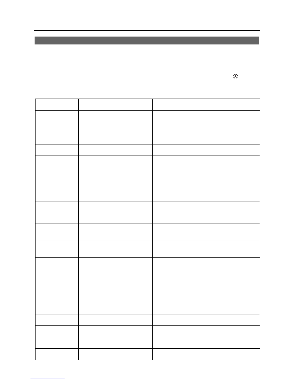
HSE Installation and Service Manual
Troubleshooting Guide Section 6
6.1 POSSIBLE PROBLEMS AND SOLUTIONS
When the service display or the operating panel is flashing, the burner controller has detected a fault. If
multiple faults exist, the temperature display shows an additional code (Refer to table 12).
After the fault has been resolved, the burner controller can be restarted by pressing the reset
on the operating panel.
Table 12 Fault Codes
Temperature
display
10, 11, 12, 13, 14 S1 CH sensor fault
Description Possible problem/solution
• Check the wires for continuity
• Replace S1
• Heat exchanger block temperature greater
than 266°F (130°C)
20, 21, 22, 23, 24 S2 CH sensor fault
0 CH Sensor fault after self-check
1 Temperature too high
• Check the wires for continuity
• Replace S2
• Check the wires for continuity
• Replace CH sensor S1 and/or S2
• Air in system
• Pump does not run
• Water flow rate too low in CH system, radiators
closed, pump setting too low
2 Incorrect wiring for S1 and S2
3 Flue gas temperature too high
4
5
No flame signal after 4 ignition
tries
No flame signal after 4 restart
tries
6 Flame detection fault
7
DHW temperature higher than
105°C
8 Blower speed incorrect
17 S3 DHW sensor open circuit
18 S8 Flue gas sensor open circuit
19 S8 Flue gas sensor short circuit
28 S7 High limit sensor open
29, 30
Faulty gas valve relay on
controller
• Check the cable harness
• Correct the connections of S1 or S2
• Check setting of gas valve
• Replace sensor S8
• Manual gas valve is not open
• Incorrect spark probe gap
• Gas inlet pressure too low
• No power to gas valve or ignition unit
• Condensate discharge blocked
• Flue or Air intake tube blocked
• Check setting of gas valve
• Replace ignition cable and spark probe
• Replace ignition unit
• Replace burner controller
• Check flow rate
• Ensure X4: 9-10 not connected unless
operating in system type 1
• Replace sensor S3
• Blower jammed by appliance front cover
• Wire between blower and casing
• Check the wires for poor contact (tacho signal)
• Replace blower
• Check the wires for continuity
• Replace S3
• Check the wires for continuity
• Replace S8
• Check the wires for short circuit
• Replace S8
• Check the wires for continuity
• Replace S7
• Replace burner controller
button
61

HSE Installation and Service Manual
6.2 BURNER FAILS TO IGNITE
Possible Problems
Manual gas shutoff valve is not open.
No
Air in the gas supply line.
No
Gas inlet pressure too low.
No
Venting system/heat exchanger blocked
No
No spark.
Ignition unit on gas unit faulty
No
Gas-air ratio not adjusted properly
No
Blower faulty
Solutions
Open the manual gas shutoff valve.
Yes
Yes
Purge the gas supply line.
Yes
Contact the gas company.
Yes
Clean heat exchanger/venting system
1. Check the cabling.
Yes
2. Check the spark probe
3. Replace the ignition unit.
Make the adjustment, see section 3.6.
Yes
1. Check the wiring.
Yes
2. Check the fuse.
3. Replace the blower if necessary.
Blower blockage
Gas valve faulty
No
No
Yes
Clean the blower.
Replace the gas valve.
Yes
62

HSE Installation and Service Manual
6.3 BURNER IGNITES WITH NOISE
Possible problems
Gas inlet pressure too high.
Incorrect spark probe gap.
Gas-air ratio not adjusted properly.
Weak spark.
Drawing for spark probe gap
No
No
No
Solutions
The gas regulator may be faulty. Contact
Yes
the gas company.
1. Replace the spark probe.
Yes
2. Adjust the spark probe gap.
Yes
Make the adjustment. see section 3.6.
1. Replace the spark probe.
Yes
2. Replace the ignition unit on the gas valve.
3. Adjust the spark probe gap.
6.4 BURNER RESONATES
Possible problems Solutions
Gas inlet pressure too low.
No
No
The gas regulator may be faulty.
Yes
Contact the gas company.
Check the venting system. Re-circulation of the flue gases.
Yes
Yes
Make the adjustment, see section 3.6. Gas-air ratio not adjusted properly.
(1.06-1.14”)
(0.18”)
63

HSE Installation and Service Manual
6.5 NO HEATING (CH)
Possible problems Solutions
Room thermostat not closed or outdoor
reset sensor faulty.
No
No voltage (24 V) output from the
burner controller.
No
Pump is not operating.
No
CH sensor S1 or S2 faulty.
No
1. Check the wiring.
2. Replace the thermostat.
Yes
3. Replace the outdoor reset sensor.
1. Check the wiring according to the
diagram.
Yes
2. Check the connector x4.
3. Replace defective burner controller.
1. Check the voltage to the pump.
2. Check the connector x4.
Yes
3. Replace defective pump.
4. Replace defective controller.
Replace sensor S1 or S2.
Yes
See Fault code display: 1 or 2.
Yes
See section 6.2, burner fails to ignite. Burner does not ignite.
6.6 REDUCED OUTPUT
Possible problems Solutions
At maximum input rating setting, the
input rating should not decrease by
more than 5%.
Yes
1. Adjust the air-gas ratio
2. Check venting system for blockage
3. Check heat exchanger for soot by
measuring emissions.
64

HSE Installation and Service Manual
6.7 CH SUPPLY WATER DOES NOT REACH CORRECT TEMPERATURE
Possible problems Solutions
Room thermostat settings not correct.
No
Supply water temperature set too low.
No
Pump speed not correct or faulty
No
No water circulation in the system.
No
The boiler input rating is not set properly
No
Scale in or soot on the heat exchanger
Check the setting and adjust if
Yes
necessary.
1. Correct the temperature setting,
see section 2.4.1 item 2 a.
Yes
2. Check the outdoor reset sensor for
short circuit.
Correct the pump setting or replace
Yes
the pump.
Check for water circulation: at least one
Yes
heating loop must be open.
Adjust the input rating setting
Yes
parameter, see section 2.4.3.
De-scale inside or clean outside of the
Yes
heat exchanger.
6.8 NO DOMESTIC HOT WATER (DHW)
Possible problems Solutions
Flow switch is faulty or not enough
water flow to trigger it
No
No voltage (24 V) output from the
burner controller.
No
Sensor S3 faulty.
No
Burner does not ignite.
1. Water flow < 2.0 l/min
Yes
2. Replace the flow switch
Check that wiring is according to the
Yes
wiring diagram
Yes
Replace sensor S3
Yes
See section 6.2, burner fails to ignite.
65

HSE Installation and Service Manual
6.9 DOMESTIC HOT WATER DOES NOT REACH CORRECT TEMPERATURE
Possible problems Solutions
Water flow rate higher than 9 l/min
No
Water temperature setting too low
No
Scale in or soot on the heat exchanger
No
Cold water temperature < 10oC
Yes
Yes
Yes
6.10 NTC TEMPERATURE SENSORS DATA
Table 13 NTC Resistances
NTC 12 kOhm
Adjust water flow rate
Set the hot water to desired temperature
De-scale inside or clean outside of the
heat exchanger.
T, °C (°F) R, ohm T, °C (°F) R, ohm T, °C (°F) R, ohm
-15 (5) 76020 25 (77) 12000 65 (149) 2752
-10 (14) 58880 30 (86) 9805 70 (158) 2337
-5 (23) 45950 35 (95) 8055 75 (167) 1994
0 (32) 36130 40 (104) 6653 80 (176) 1707
5 (41) 28600 45 (113) 5522 85 (185) 1467
10 (50) 22800 50 (122) 4609 90 (194) 1266
15 (59) 18300 55 (131) 3863 95 (203) 1096
20 (68) 14770 60 (140) 3253 100 (212) 952
66

HSE Installation and Service Manual
Notes
67

HSE Installation and Service Manual
Notes
68
 Loading...