

Super Hot EPP SERIES, EPP-40 TO, EPP-120 Installation And Service Manual
EPP SERIES – INDIRECT WATER HEATERS
INSTALLATION AND SERVICE MANUAL
FOR MODELS EPP-40 TO EPP-120
SEE REAR COVER FOR INDEX
Read this instruction manual before installation, operation, or service. Failure to follow
the instructions in this manual may result in severe personal injury, death or substantial
property damage. Installation and service must be performed by a qualified service
technician.
Manufacturers of Gas and Electric Boilers, Stainless Steel Tanks, Heat Exchangers and Electric Boosters
94 Riverside Drive, North Vancouver, B.C. V7H 2M6 • Telephone (604) 929-1214 • FAX (604) 929-5184
PN5242745 Price $5
Manufactured by
Allied Engineering Company
Division of E-Z-Rect Manufacturing Ltd.
Branches: Calgary • Edmonton • Toronto
EPP SERIES INDIRECT WATER HEATERS – Installation and Service Manual
180 152 314 309 176,000
Maximum Coil Temper
ature: 210°F
The Super Hot product improvement program may result in changes to design and/or specifications being made without notice.
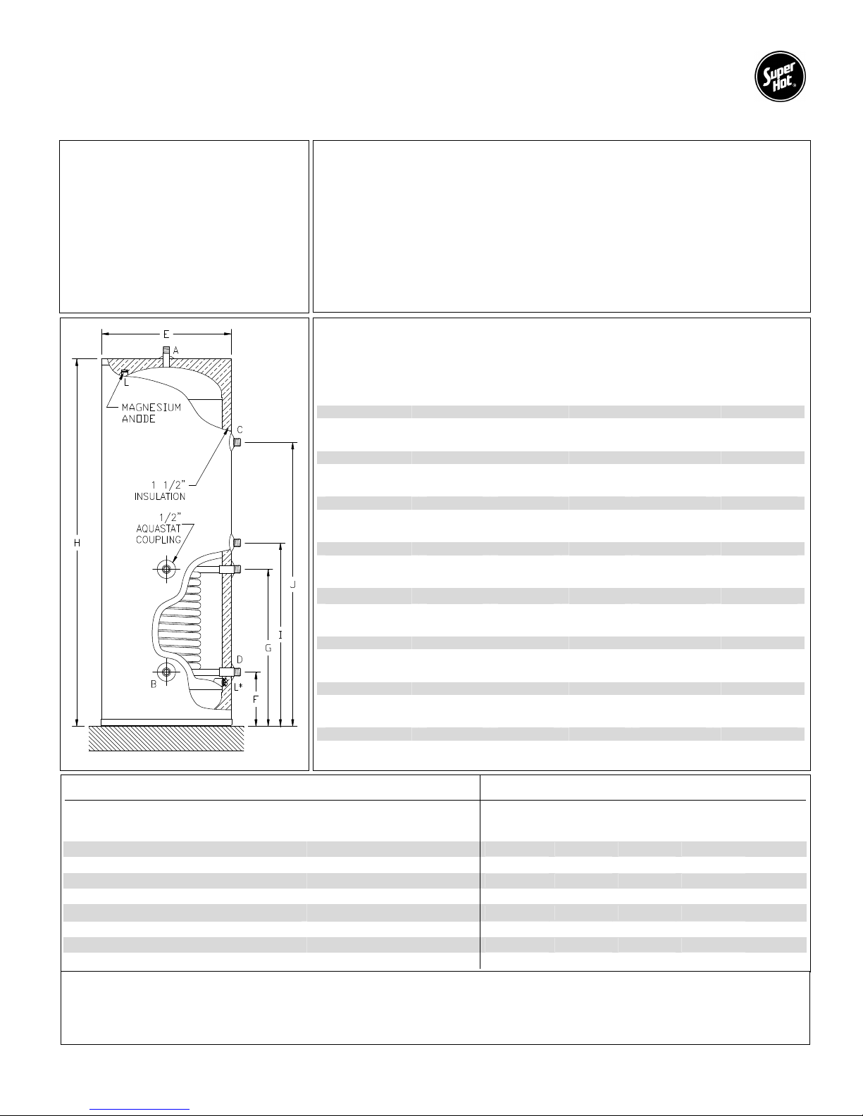
DIMENSIONS AND SPECIFICATIONS
Storage Sizes (Nominal)
EPP-40-SC 40 US Gal.
EPP-60-SC 60 US Gal.
EPP-60-SCR 60 US Gal.
EPP-60-DC 60 US Gal.
EPP-80-SC 80 US Gal.
EPP-80-DC 80 US Gal.
EPP-120-SC 120 US Gal.
EPP-120-DC 120 US Gal.
SC = Single Coil
DC = Double Coil
SCR = Crawl Space Design (Single Coil)
Features Quality Construction
• Fast Recovery Time • 316L Stainless Steel Tank
• Highest Heat Transfer Efficiency • 316L Stainless Steel Heat Exchanger
• Low Standby Heat Loss • Aquastat and Stainless Steel Thermowell
• Easy Installation • Magnesium Anode
• Warranty: 10 Year for Residential.
See warranty for details.
Note: Single Coil heat exchanger uses 1” O.D. x 30 ft long Stainless Steel tube.
Maximum Operating Pressure: 150 psi
Maximum Tank Temperature: 150°F
• Passivated for additional Corrosion Protection
Recovery
Model Number
EPP-40-SC 200 66 194 226 129,000
190 63 176 205 117,000
180 60 159 184 105,000
EPP-60-SC 200 86 214 226 129,000
190 83 196 205 117,000
180 80 179 184 105,000
EPP-60-SCR 200 86 214 226 129,000
190 83 196 205 117,000
180 80 179 184 105,000
EPP-60-DC 200 102 313 383 219,000
190 97 284 346 198,000
180 92 253 309 176,000
EPP-80-SC 200 105 232 226 129,000
190 102 215 205 117,000
180 100 198 184 105,000
EPP-80-DC 200 122 333 383 219,000
190 117 304 346 198,000
180 112 273 309 176,000
EPP-120-SC 200 146 274 226 129,000
190 143 256 205 117,000
180 140 239 184 105,000
EPP-120-DC 200 163 375 383 219,000
190 157 345 346 198,000
Inlet From
(Based on Boiler Flow Rate of 10 GPM)
Boiler
Temp.°°°°F
1st 10 Min.
Delivery
@ 135 °°°°F
US Gal.
1st Hour
Delivery
@ 135 °°°°F
US Gal.
Continuous
Delivery
@115 °°°°F
US GPH
Thermal Input
Requirements
Btu/Hr
Dimensions Fitting Sizes Weight
EPP-40-SC 21” 7 5/8” 24 1/8” 42 5/16” - EPP-60-SC 21” 7 5/8” 24 1/8” 60 5/16” - EPP-60-SCR* 27” 10 13/16” 27 5/16” 36 3/8” - EPP-60-DC 21” 7 5/8” 24 1/8” 60 5/16” 30 1/8” 46 5/8”
EPP-80-SC 23” 10 1/4” 26 3/4” 63 5/16” - EPP-80-DC 23” 10 1/4” 26 3/4” 63 5/16” 32 7/8” 49 1/4”
EPP-120-SC 27” 10 11/16” 27 3/16” 64 5/8” - EPP-120-DC 27” 10 11/16” 27 3/16” 64 5/8” 33 3/16” 49 11/16”
* Anode for EPP-60-SCR located at bottom of tank instead of top.
Also available:
• “Stacker” Indirect Fired Hot Water Tank in 40 US gallon – boiler can be stacked on casing to save floor space
• EPP Storage Tanks in 40, 60, 80, and 120 US gallon
E F G H I J
A
Hot Water
Outlet
¾” ¾” 1” 1”
¾” ¾” 1” 1”
¾” ¾” 1” 1”
¾” ¾” 1” 1”
1 ” 1 ” 1” 1”
1 ” 1 ” 1” 1”
1 ½” 1 ½” 1” 1”
1 ½” 1 ½” 1” 1”
B
Cold
Water Inlet
Inlet from
2
C
Boiler
D
Outlet to
Boiler
144 LB
182 LB
164 LB
196 LB
198 LB
212 LB
236 LB
256 LB

EPP SERIES INDIRECT WATER HEATERS – Installation and Service Manual
1.0 PRE-INSTALLATION
1.1 RECEIVING
INSPECT SHIPMENT FOR POSSIBLE DAMAGE. All goods are carefully manufactured, inspected,
checked and packed by experienced workers. The manufacturer's responsibility ceases upon delivery of
goods to the carrier in good condition. Any claims for damage and/or shortage in shipment or non-delivery
must be filed immediately against the carrier by the consignee.
Use care when receiving and unpacking the tank. Dropping the tank may cause damage and prevent safe
and proper operation.
1.2 INSTALLATION CODES AND REQUIREMENTS
All applicable national, provincial/state, and local codes, laws, regulations, and ordinances must be
followed. They expand on and take precedence over any recommendations in this booklet. Authorities
having jurisdiction shall be consulted before installations are made.
If an external electrical source is utilized, the hot water tank, when installed, must be electrically grounded
in accordance with local codes or, in the absence of local codes, with the National Electrical Code,
ANSI/NFPA 70 (current edition) and/or the Canadian Electrical Code, CSA C22.1 Part 1 (current edition).
If there is any conflict in the above requirements, the more stringent requirement applies.
The installation and service must also conform to the additional requirements in this manual. If there is
any conflict with a requirement in this manual and a code requirement, the code requirement must be
followed.
1.3 LOCATION
• This tank should not be placed where freezing might occur and is not to be installed outdoors.
• This tank is designed for vertical installation. Install the tank on an area that is stable, flat, level
and capable of supporting the weight of the tank when filled with water. CAUTION: Failure to
support and stabilize the water heater could result in severe personal injury, death or substantial
water damage.
• Although minimal clearance is required for this tank, ensure that there is sufficient room for the
water heater to access all of the fittings easily. We recommend a service clearance of 24”
around plumbing connections.
• CAUTION: The tank should be located in an area where leakage of the indirect water heater or
connections will not result in damage to the area adjacent to the appliance or to lower floors of the
structure. When such locations cannot be avoided, it is recommended that a suitable drain pan,
adequately drained (connected to a drain), be installed under the tank.
• This tank must be installed such that any electronic components are protected from water
(dripping, spraying, rain, etc.) during appliance operation and service.
• Avoid heat loss and friction loss by locating the tank as close to the boiler as possible. Further
heat loss should be avoided by insulating the pipe.
• For the fastest delivery of hot water, locate the water heater in a position central to the points of
use.
• DANGER - Risk of Explosion: Do not use or store gasoline or other flammable fuels or
chemicals which have flammable vapors near the tank. The vapors may be ignited by the heat or
electronic components of the tank.
3

EPP SERIES INDIRECT WATER HEATERS – Installation and Service Manual
1.4 OPERATING RESTRICTIONS
CAUTION: Single wall heat exchangers must use a heat transfer medium such as water or other non-
toxic fluids having a toxicity rating of Class 1, as listed in Clinical Toxicology of Commercial Products
(current edition). The pressure of the heat transfer medium must be limited to a maximum of 150psi by an
approved pressure relief valve.
Maximum working pressure of the tank is 150psi.
1.5 WATER QUALITY
Always use good quality water to prolong the life of the tank. Water that is safe to drink and even city
water is not necessarily good quality water for the tank. The use of filters can prevent corrosion and
reduce sediments inside the tank. Water hardness, pH, and chlorides must be controlled to normal levels.
• PH levels must be between 6.0 and 8.0 and dissolved chlorides below 100ppm.
If you are unsure, use a water softening system or consult a qualified water treatment expert.
NOTE: All improper use as detailed above could void the warranty of the tank.
4

EPP SERIES INDIRECT WATER HEATERS – Installation and Service Manual
2.0 PIPING AND PLUMBING
2.1 BOILER SIDE PLUMBING
Connect boiler out (hot) supply piping to the fitting marked “boiler in” on the water tank. The “boiler out”
fitting on the tank should be piped to the boiler return. Use Teflon tape, pipe dope, or both on all threaded
fittings. When installing the pump make sure that the direction arrow is pointing in the same direction as
the flow. The use of shut off valves and dielectric unions are recommended when installing your water
tank to simplify future service requirements.
To prevent a back flow through the water heater when heating a radiant system, a check valve or back
flow preventer must be installed.
The heat output of the tank is based on the temperature and flow rate from the boiler supply. To ensure
that the minimum flow rate is provided, use at least 1 inch pipe size (from boiler to tank) and a zone valve
with a minimum 1 inch diameter and flow coefficient of at least CV = 8.
Hot Water Priority
A boiler system connected to multiple zones may be installed so that domestic water heating will be given
priority over other zone heating. If hot water priority is used, preventative measures must be taken to
ensure hot water priority during cold weather conditions does not result in freezing damage to the other
zones.
Sample Systems
Although there are unlimited possibilities for your indirect water heater system, some typical installations
are described and shown below. Note that all heating zones can be controlled either by using circulators
(pumps) or zone valves as long as correct flow is provided.
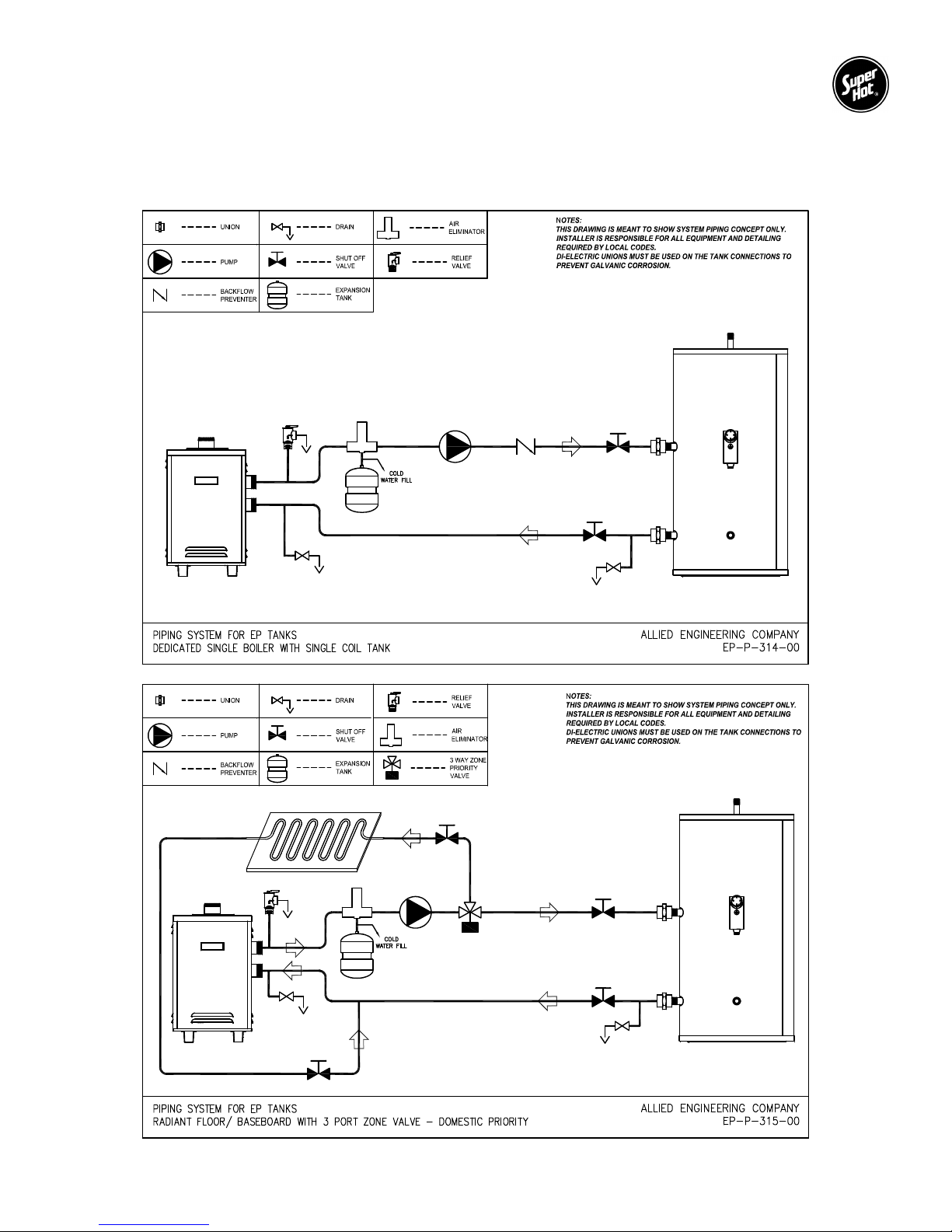
Dedicated Single Boiler with Single Coil Tank
Radiant Floor / Baseboard with 3 Port Zone Valve – Domestic Priority
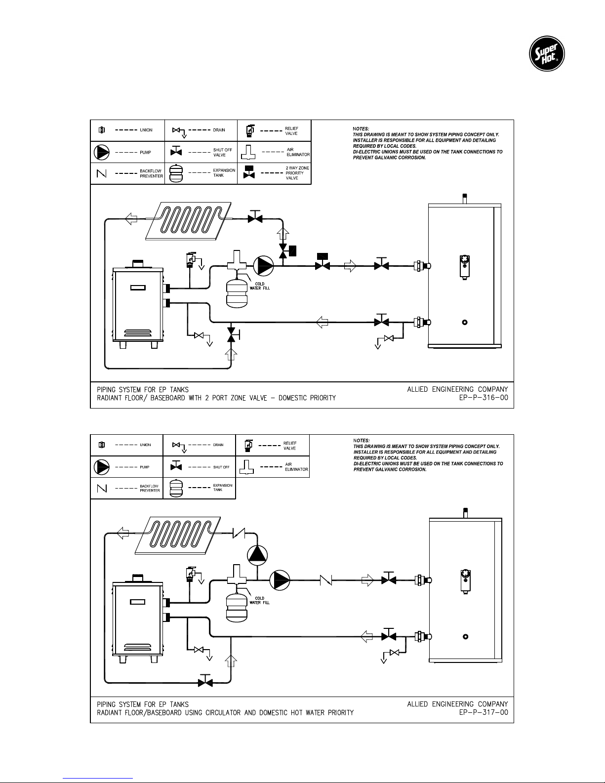
Radiant Floor / Baseboard with 2 Port Zone Valve – Domestic Priority
Radiant Floor / Baseboard Using Circulator and Domestic Hot Water Priority
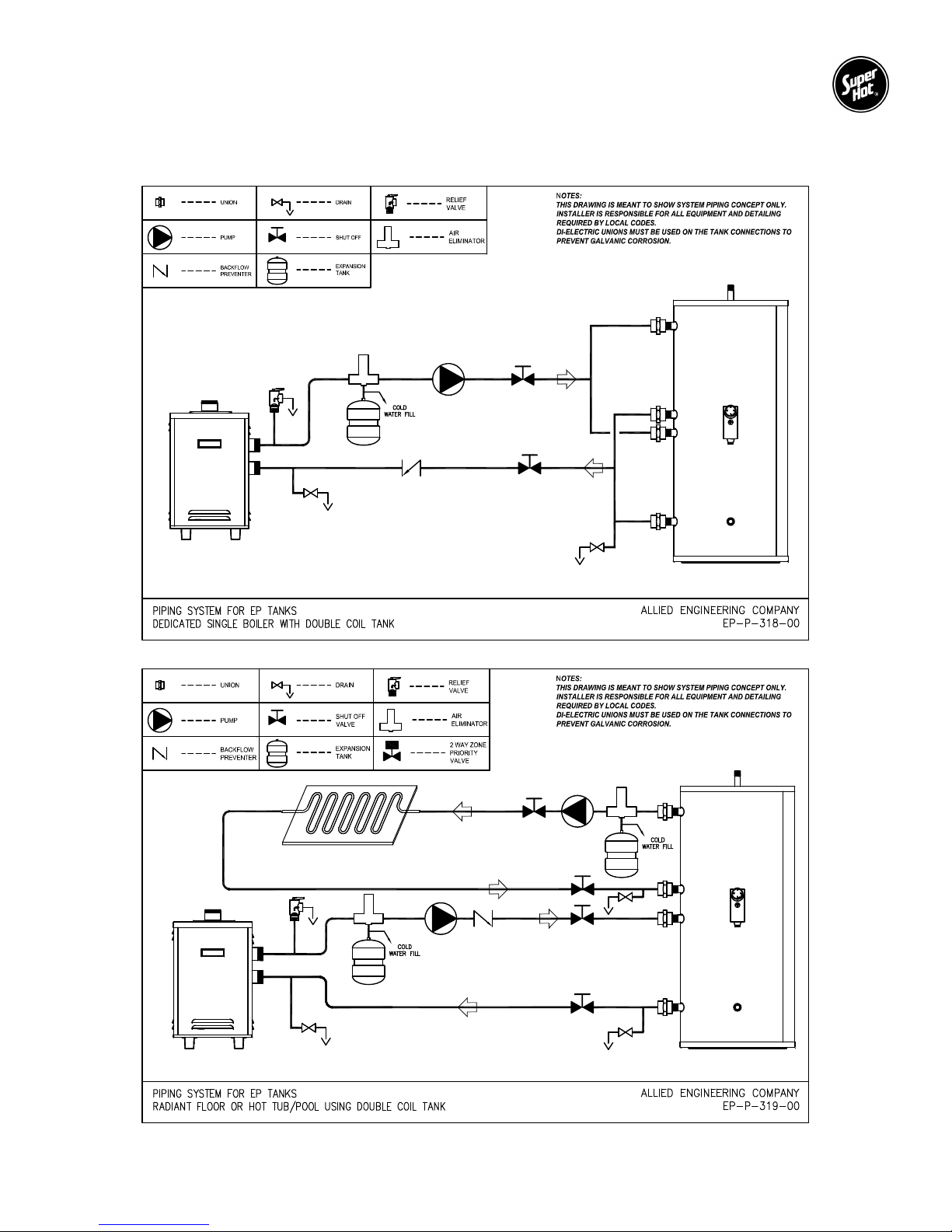
Dedicated Single Boiler with Double Coil Tank
Radiant Floor or Hot Tub / Pool Using Double Coil Tank
Multiple Water Heaters – Domestic Priority
Multiple Water Heaters Piped in Series
Standard Circulators Zone:
Run the same as a standard heating zone except one zone is piped to the water heater and can be
prioritized by correct use of the control valve. Ensure that the circulator is sized correctly to allow the boiler
water to flow at the correct rate.
Zone Valve System:
Run the same as a standard heating zone except one zone is piped to the water heater and can be
prioritized with correct use of the zone valves. Ensure that the circulator is sized correctly to allow the
boiler water to flow at the correct rate. Do not use a zone valve less than 1 inch diameter and CV = 8.
3-way Zone Valve System:
For prioritizing your water heater, a 3-way zone valve can be installed into your system. This system
overrides all other “calls for heat” when there is a demand from the water heater aquastat. All the boiler
water is then diverted to the water heater. There are three ports on a 3-way valve: a common port, a
normally closed port, and a normally open port. The common port is connected to the boiler side; the
normally open port connected to the heating zone and the normally closed is connected to the water
heater coil. The boiler water flows through the heating zone, until the water heater aquastat demands
more heat. The zone valve is then activated and the boiler water is diverted to the water heater; once the
requested water temperature is achieved the aquastat will shut off power to the zone valve and the boiler
water will be diverted back to the heating zone.
5
EPP SERIES INDIRECT WATER HEATERS – Installation and Service Manual
2.2 INSTALLATION DIAGRAMS
Sample Schematics Boiler Side Piping
6
EPP SERIES INDIRECT WATER HEATERS – Installation and Service Manual
7
EPP SERIES INDIRECT WATER HEATERS – Installation and Service Manual
Double Coil for larger hot water demand
8
 Loading...