

Super Hot EPJ-40-SC, EPJ-56-SC, EPJ-79-SC, EPJ-119-SC Installation And Service Manual

INSTALLATION AND SERVICE MANUAL
Allied Engineering Company
EPJ-SERIES INDIRECT WATER HEATERS
FOR MODELS: EPJ-40-SC, EPJ-56-SC, EPJ-79-SC, EPJ-119-SC
WARNING
Read this manual and all information provided with the appliance before installation,
operation, or service. Failure to follow the instructions may result in severe personal
injury, death or substantial property damage. Installation and service must be
performed by a qualified service technician. Please keep this manual for future
reference.
Manufacturers of Gas and Electric Boilers, Heat Exchangers, Electric Boosters, Indirect Tanks
94 Riverside Drive, North Vancouver, B.C. V7H 2M6 Telephone 604-929-1214 www.alliedboilers.com
PN11483042
Division of E-Z-Rect Manufacturing Ltd.
Branches: Calgary Edmonton Toronto Denver

EPJ SERIES INDIRECT WATER HEATERS – Installation and Service Manual
Table of Contents
Section Page
SECTION 1 - DIMENSIONS AND SPECIFICATIONS ................................................................................. 3
1.1 SPECIFICATIONS .............................................................................................................................. 3
1.2 DIMENSIONS ...................................................................................................................................... 4
1.3 PRESSURE DROP CHART ................................................................................................................ 5
SECTION 2 - PRE-INSTALLATION ............................................................................................................. 6
2.1 RECEIVING ......................................................................................................................................... 6
2.2 INSTALLATION CODES AND REQUIREMENTS ............................................................................... 6
2.3 LOCATION .......................................................................................................................................... 6
2.4 OPERATING RESTRICTIONS............................................................................................................ 7
2.5 WATER QUALITY ............................................................................................................................... 7
SECTION 3 – WATER PIPING ..................................................................................................................... 8
3.1 BOILER WATER PIPING .................................................................................................................... 8
3.2 DOMESTIC WATER PIPING ............................................................................................................. 12
3.3 T&P RELIEF VALVE .......................................................................................................................... 13
3.4 WATER HAMMER ............................................................................................................................. 13
SECTION 4 – WIRING… ............................................................................................................................ 14
SECTION 5 - STARTUP AND ADJUSTMENT .......................................................................................... 19
5.1 PRE-START UP CHECKLIST ........................................................................................................... 19
5.2 STARTUP INSTRUCTIONS .............................................................................................................. 19
SECTION 6 - WATER ADJUSTMENT ....................................................................................................... 20
6.1 CONTROL AQUASTAT ..................................................................................................................... 20
6.2 AQUASTAT TEMPERATURE ........................................................................................................... 20
6.3 TEMPERATURE ADJUSTMENT ...................................................................................................... 21
SECTION 7 - SERVICE AND MAINTENANCE .......................................................................................... 22
7.1 GENERAL OPERATION ................................................................................................................... 22
7.2 ELECTRONIC ANODE ...................................................................................................................... 22
7.3 ANNUAL SERVICE ........................................................................................................................... 23
7.4 MONTHLY SERVICE ........................................................................................................................ 23
SECTION 8 - TROUBLESHOOTING GUIDE ............................................................................................. 24
SECTION 9 - WARRANTY REGISTRATION ............................................................................................. 25
SECTION 10 - NOTES ................................................................................................................................ 27
EPJ SERIES INDIRECT WATER HEATERS – Installation and Service Manual
Dimensions and Specifications Section 1
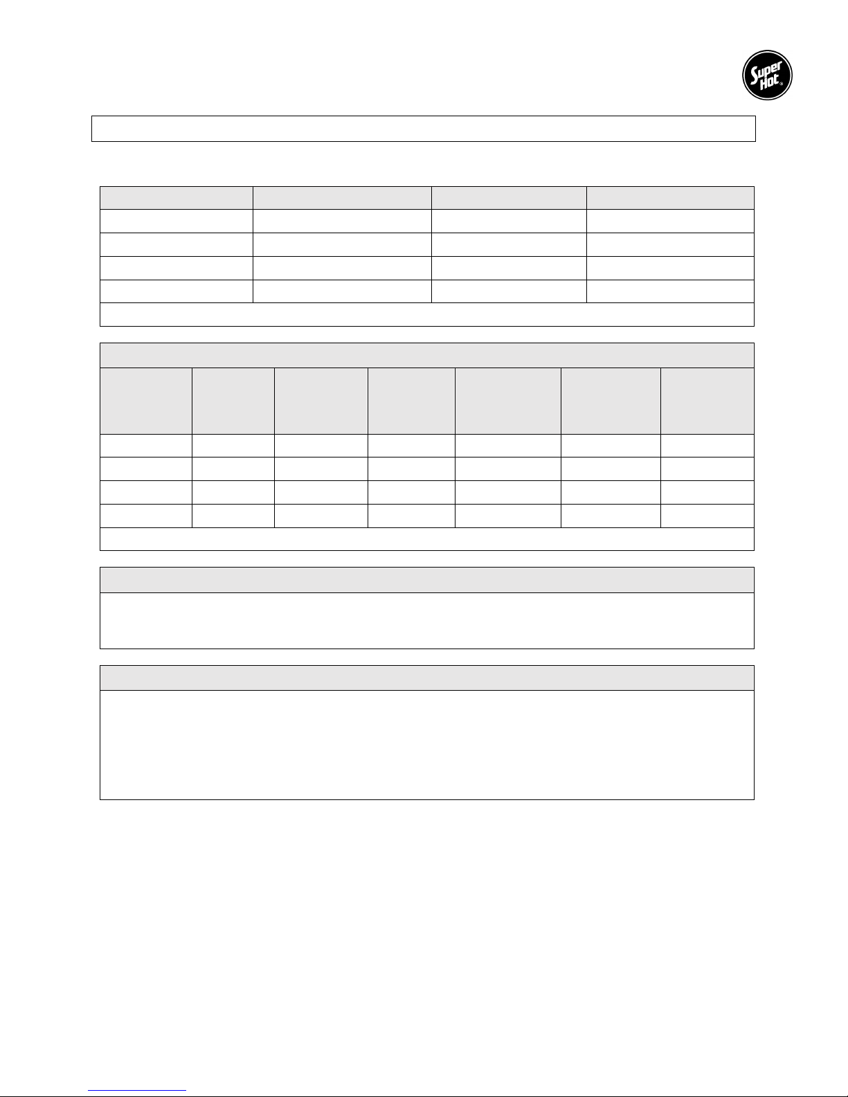
1.1 SPECIFICATIONS
Model Storage Capacity (US Gal.) R value (ft2h°F/Btu) Shipping Weight (lbs)
EPJ-40-SC
EPJ-56-SC
EPJ-79-SC
EPJ-119-SC
Note: SC = Single Coil
38.9 9.8 66
55.3 9.8 96
78.1 9.6 115
115.0 9.5 189
PERFORMANCE
Boiler
Water Flow
Model
EPJ-40-SC
EPJ-56-SC
EPJ-79-SC
EPJ-119-SC
* Note: Ratings are based on 180°F boiler supply and 58°F entering cold water
(US GPM)
Rate
8 2.6 194 160 102,000 0.6
8 3.2 236 189 119,000 0.5
13 10.7 348 281 179,000 0.5
15 7.5 492 391 250,000 0.4
Pressure
Drop
Through Coil
(ft. w.c)
1st Hour
Delivery
@ 135°F
(US Gal.)
Continuous
Delivery
@ 135°F
(US GPH)
OPERATING RESTRICTIONS
Maximum Temperature for Tank: 150°F
Maximum Boiler Water Temperature: 210°F
Maximum Working Pressure for Tank: 150 PSIG
MATERIALS OF CONSTRUCTION
Tank: AISI 444 Stainless Steel
Coil: AISI 444 Stainless Steel
Process: Pickled and Passivated for corrosion protection
Insulation: EPS Foam Insulation (2 inch thickness)
Jacket: Polypropylene
Testing: Each tank is Factory Pressure Tested to 300 PSI
Boiler
Output
Required
(Btu/h)
Standby
Loss
(°F/hr)
3
EPJ SERIES INDIRECT WATER HEATERS – Installation and Service Manual
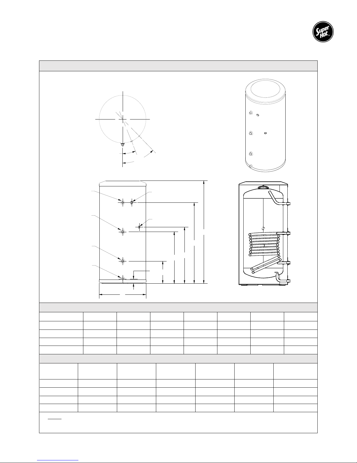
1.2 DIMENSIONS
EPJ DIMENSIONS DIAGRAM
22.5°
45°
HOT WATER
BOILER WATER
BOILER WATER
COLD WATER
INLET/DRAIN
OUTLET
INLET
OUTLET
G
RELIEF VALVE
SENSOR WELL
D
F
E
A
B
C
DIMENSIONS (Inches)
Model A B C D E F G
EPJ-40-SC 46 ⅞ 37 25 ¾ 23 ⅝ 10 ¼ 2 21 ⅞
EPJ-56-SC 62 ¾ 52 ¾ 28 ⅞ 26 ¾ 10 ¼ 2 21 ⅞
EPJ-79-SC 69 ¾ 60 ½ 31 28 ⅞ 9 ⅞ 1 ⅞ 23 ¾
EPJ-119-SC 65 ¾ 52 ¾ 39 ⅜ 37 ¼ 11 ½ 2 28 ⅞
CONNECTIONS (NPT)
Model
Cold Water
Inlet
Hot Water
Outlet
Boiler Water
Outlet
Boiler Water
Inlet
Relief Valve Sensor Well
EPJ-40-SC ¾" M ¾" M 1" M 1" M ¾" F ½" F
EPJ-56-SC ¾" M ¾" M 1" M 1" M ¾" F ½" F
EPJ-79-SC ¾" M ¾" M 1" M 1" M ¾" F ½" F
EPJ-119-SC
Notes
1. Aquastat w/ well, T&P Relief Valve, and Combi Tee/Drain Valve supplied as an option.
2. Dimensions and Specifications subject to change without notice.
1 ¼" M 1 ¼" M 1 ¼" M 1 ¼" M 1" F ½" F
4
EPJ SERIES INDIRECT WATER HEATERS – Installation and Service Manual
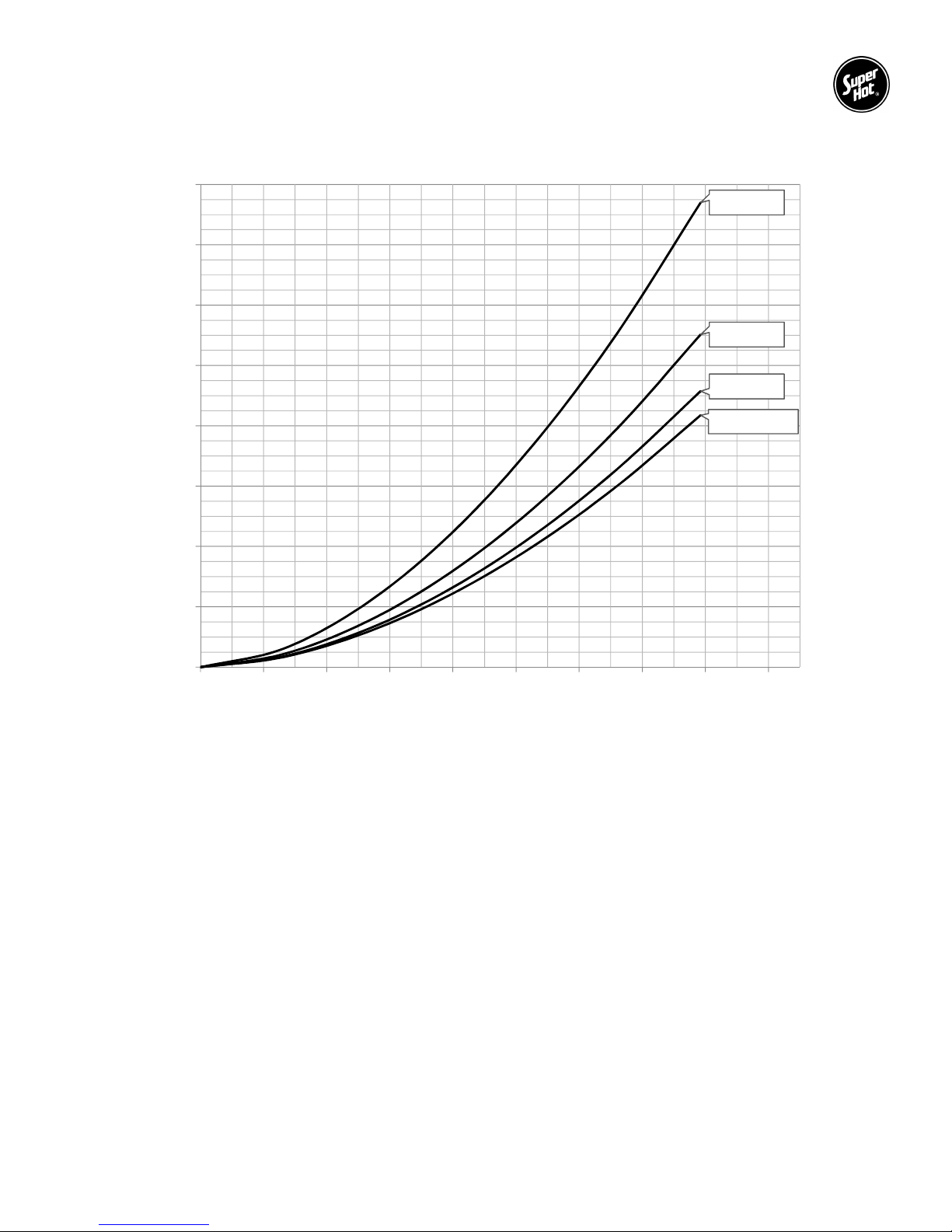
1.3 PRESSURE DROP CHART
16
EPJ-79-SC
14
12
EPJ-56-SC
10
EPJ-40-SC
8
6
Pressure Drop (Ft of Head)
4
2
0
0 2 4 6 8 10 12 14 16 18
Flow Rate (US GPM)
Boiler Water Pressure Drop through Coil
EPJ-119-SC
5

EPJ SERIES INDIRECT WATER HEATERS – Installation and Service Manual
Pre-Installation Section 2
2.1 RECEIVING
INSPECT SHIPMENT FOR POSSIBLE DAMAGE. All goods are carefully manufactured, inspected,
checked and packed by experienced workers. The manufacturer's responsibility ceases upon delivery of
goods to the carrier in good condition. Any claims for damage and/or shortage in shipment or non-delivery
must be filed immediately against the carrier by the consignee.
Use care when receiving and unpacking the tank. Dropping the tank may cause damage and prevent safe
and proper operation.
2.2 INSTALLATION CODES AND REQUIREMENTS
All applicable national, provincial/state, and local codes, laws, regulations, and ordinances must be
followed. They expand on and take precedence over any recommendations in this booklet. Authorities
having jurisdiction shall be consulted before installations are made.
If an external electrical source is utilized, the indirect water heater must be electrically grounded and
installed in accordance with local codes or, in the absence of local codes, with the National Electrical Code,
ANSI/NFPA 70 (current edition) and/or the Canadian Electrical Code, CSA C22.1 Part 1 (current edition).
If there is any conflict in the above requirements, the more stringent requirement applies.
The installation and service must also conform to the additional requirements in this manual. If there is any
conflict with a requirement in this manual and a code requirement, the code requirement must be followed.
2.3 LOCATION
DANGER - Risk of Explosion: Do not use or store gasoline or other flammable fuels or chemicals
which have flammable vapors near the tank. The vapors may be ignited by the heat or electronic
components of the tank.
WARNING: The indirect water heater should be located in an area where water leakage of the
tank or its connections will not result in damage to the area adjacent to the appliance or to lower
floors of the structure. When such locations cannot be avoided, a suitable drain pan must be
installed under the appliance and the drain pan must be connected to a drain of adequate capacity.
Failure to comply with the above could result in severe personal injury, death or substantial property
damage.
WARNING: Failure to support and stabilize the water heater could result in severe personal injury,
death or substantial property damage. Do not lean items against the water heater. Avoid
unnecessary contact with the water heater.
This tank is designed for vertical installation. Install the tank on an area that is stable, flat, level and
capable of supporting the weight of the tank when filled with water.
This tank should not be placed where freezing might occur and is not to be installed outdoors.
Although minimal clearance is required for this tank, ensure that there is sufficient room around the
tank to access all of the fittings easily. We recommend a service clearance of 24 inches around
the piping connections.
This tank must be installed such that any electronic components are protected from water (dripping,
spraying, rain, etc.) during appliance operation and service.
Avoid heat loss and friction loss by locating the tank as close to the boiler as possible. Further heat
loss should be avoided by insulating the pipe.
For the fastest delivery of hot water, locate the water heater in a position central to the points of
use.
6

EPJ SERIES INDIRECT WATER HEATERS – Installation and Service Manual
2.4 OPERATING RESTRICTIONS
WARNING: The heat transfer medium (including additives, if used) must be water or another non-toxic
fluid having a toxicity rating of Class 1, as listed in Clinical Toxicology of Commercial Products (current
edition). The pressure of the heat transfer medium must be limited to 30 PSIG by an approved pressure
relief valve.
The domestic water in the tank must be limited to a maximum temperature of 150°F and maximum pressure
of 150 PSIG by an approved T&P relief valve.
Maximum Water Temperature for Tank: 150°F
Maximum Water Temperature for Coil: 210°F
Maximum Working Pressure for Tank: 150 PSIG
2.5 WATER QUALITY
Always use good quality water to prolong the life of the tank. Water that is safe to drink and even city water
is not necessarily good quality water for the tank. The use of water treatment and filters can prevent
corrosion and reduce sediment in the tank. Water hardness, pH, and chlorides must be controlled to normal
levels.
PH levels must be between 6.0 and 8.0
Chlorine, chlorides and aggressive sulfates concentrations must be below 100 parts per
million.
If you are unsure, use a water softening system or consult a qualified water treatment expert.
NOTE: All improper use as detailed above could void the warranty of the indirect water heater.
7

EPJ SERIES INDIRECT WATER HEATERS – Installation and Service Manual
Water Piping Section 3
3.1 BOILER WATER PIPING
Connect boiler out (hot) supply piping to the “BOILER WATER IN” fitting on the tank. The “BOILER WATER
OUT” fitting on the tank should be piped to the boiler return. Use Teflon tape, pipe dope, or both on all
threaded fittings. When installing the pump make sure that the direction arrow is pointing in the same
direction as the flow. The use of shut off valves and brass or dielectric unions are recommended when
installing your water heater for future service convenience and to prevent galvanic corrosion.
To prevent heat loss due to gravity flow from the coil, a check valve or heat trap with a minimum 12 inch
drop should be installed as close to the “boiler water in” fitting as practical. For systems with two or more
circulators, a check valve may be used to prevent thermal siphoning from circulator draw.
The heat output of the tank is based on the temperature and flow rate from the boiler supply. To ensure
that the minimum flow rate is provided, the diameter of the pipe between the boiler and tank must be
equivalent to or larger than the diameter of Boiler Water connections on the tank (see section 1.2
Dimensions). There should be no excessive restrictions due to components (e.g. zone valve, check valve,
fittings) or the design of the piping system (e.g. length of run, number of elbows). If a zone valve is used, it
should be a minimum of 1” full port and have a flow coefficient of at least CV = 8.
Hot Water Priority
A boiler system connected to multiple zones may be installed so that domestic water heating will be given
priority over other zone heating. If hot water priority is used, preventative measures must be taken to ensure
hot water priority during cold weather conditions does not result in freezing damage to the other zones.
Zone Circulator System
This system is run the same as a standard heating zone except one zone is piped to the water heater and
can be prioritized by using a zone circulator (pump).
Zone Valve System
This system is run the same as a standard heating zone except one zone is piped to the water heater and
can be prioritized by using a zone valve.
3-way Zone Valve System
This system overrides the heat demands of all other zones when there is a heat demand from the water
heater aquastat and diverts all boiler water to the water heater. There are three ports on a 3-way valve: a
common port, a normally closed port, and a normally open port. The common port is connected to the boiler
supply side, the normally open port is connected to the heating zones, and the normally closed port is
connected to the “boiler water in” fitting of the water heater. The 3-way valve normally allows boiler water
to flow through the normally open port to the heating zones. When there is a heat demand from the water
heater aquastat, the 3-way valve diverts all boiler water through the normally closed port to the water heater.
Sample Systems
Although there are many possible system designs for your indirect water heater, a few of the most common
are described below. Note that all zones can be controlled by using either circulators or zone valves as long
as the adequate flow is provided. Always ensure that the circulator is correctly sized to provide the required
Boiler Water Flow Rate to the water heater.
Dedicated Single Boiler with Single Tank
Radiant Floor / Baseboard with 3 Port Zone Valve – Domestic Priority
Radiant Floor / Baseboard with 2 Port Zone Valve – Domestic Priority
Radiant Floor / Baseboard Using Circulator and Domestic Hot Water Priority
Multiple Water Heaters – Domestic Priority
Multiple Water Heaters Piped in Series
8

EPJ SERIES INDIRECT WATER HEATERS – Installation and Service Manual
3.2 BOILER WATER PIPING DIAGRAMS
BOILER WATER PIPING
9
 Loading...