

Super Hot AAA3000, AAA720, AAA480, AAA600, AAA840 Installation And Service Manual
...
nstallation, adjustment, alteration, service or maintenance can cause property
Please carefully read this manual. For assistance or
WARNING
INSTALLATION AND SERVICE MANUAL
AAA SERIES GAS BOILERS
FOR MODELS AAA-480 TO AAA-3000
Featuring the BTC SERIES Controller on 1 & 2 stage models
See rear cover for Index
Improper i
damage, injury, or loss of life
additional information, consult a qualified installer, service agency or the gas supplier.
Allied Engineering Company
Manufacturers of Gas and Electric Boilers, Stainless Steel Tanks, Heat Exchangers and Electric Boosters
94 Riverside Drive, North Vancouver, B.C. V7H 2M6 • Telephone (604) 929-1214 • www.alliedboilers.com
PN3362421
Division of E-Z-Rect Manufacturing Ltd.
Branches: Calgary • Edmonton • Toronto
.
Manufactured by

AAA SERIES GAS BOILERS
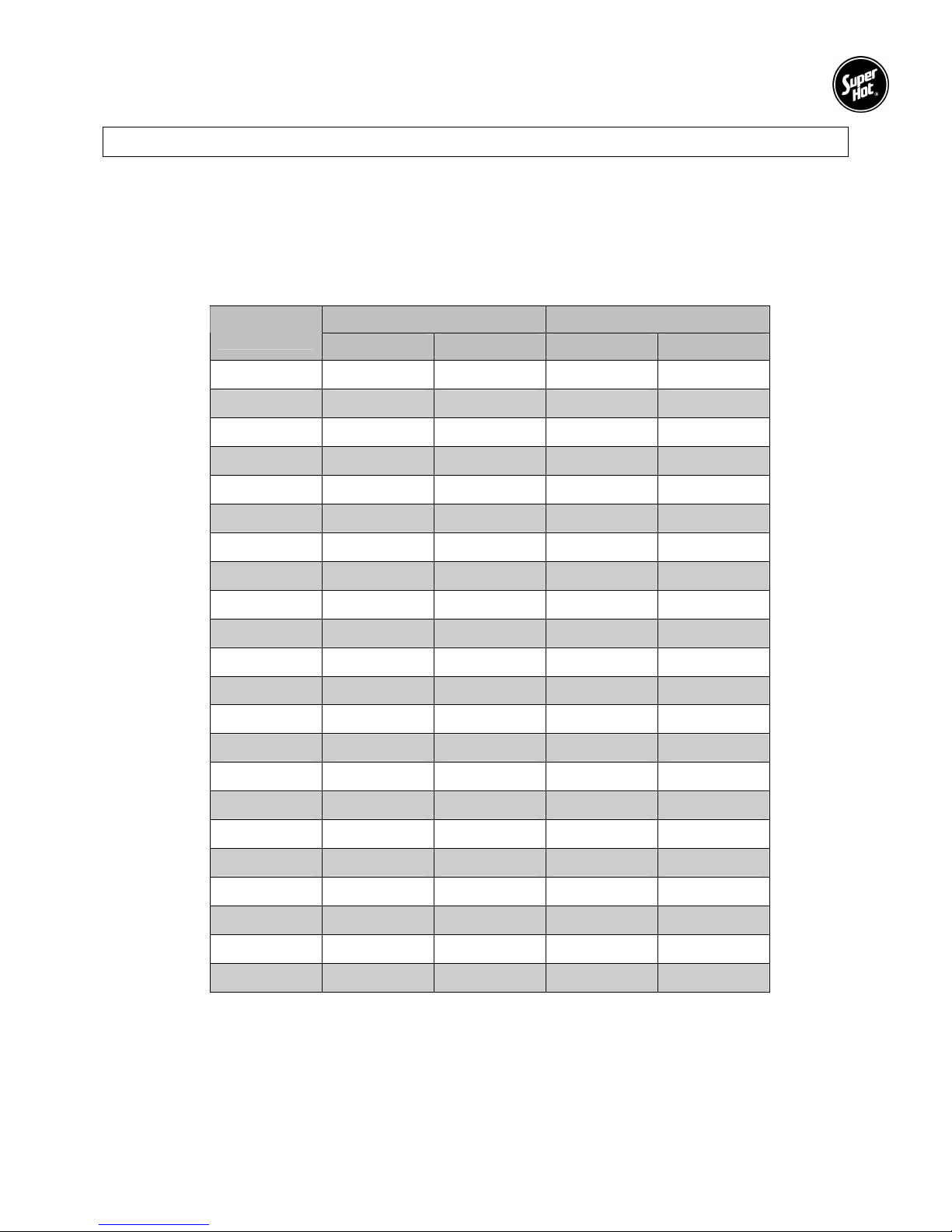
DIMENSIONS AND SPECIFICATIONS
Standard Model Includes:
• Electronic Ignition
• Stainless Steel Burners
• Gas Valve
• Redundant Gas Valve
• BTC SERIES Microcontroller
(single and two stage models only)
• Operating/Safety High Limit Aquastat
• Safety High Limit Aquastat
• Temperature / Pressure Gauge
• A.S.M.E. Pressure Relief Valve 30 p.s.i.
• Drain Valve
• Draft Hood
• Transformer
• Control Panel Enclosure
• Main On/Off Switch with Indicator Light
The Super Hot product improvement program may result in changes to the design and/or specifications being made without notice.
MODEL
NUMBER
AAA480 480 141 408 120 12.2 24 61.0 10.5 26.7 10 25.4 68.9 175.0 12.0 30.5 1” 5.56 21.0 675 307
AAA600 600 176 510 149 15.2 27 68.6 10.5 26.7 12 25.4 68.9 175.0 13.5 34.3 1” 6.75 25.5 725 330
AAA720 720 211 612 179 18.3 30 76.2 10.5 26.7 12 30.5 71.2 181.0 15.0 38.1 1” 7.95 30.1 790 359
AAA840 840 246 714 209 21.3 33 83.8 10.5 26.7 14 35.6 72.9 185.1 16.5 41.9 1” 9.14 34.6 860 391
AAA960 960 281 816 239 24.4 36 91.4 10.5 26.7 14 35.6 72.9 185.1 18.0 45.7 1 1/4” 10.34 39.1 940 427
AAA1080 1080 317 918 269 27.4 39 99.0 10.5 26.7 16 40.6 76.0 193.0 19.5 49.5 1 1/4” 11.53 43.6 990 450
AAA1200 1200 352 1020 299 30.5 42 106.7 10.5 26.7 16 40.6 76.0 193.0 21.0 53.3 1 1/4” 12.73 48.2 1050 477
AAA1320 1320 387 1122 329 33.5 45 114.3 10.5 26.7 18 45.7 77.3 196.3 22.5 57.2 1 1/4” 13.92 52.7 1140 518
AAA1440 1440 422 1224 359 36.6 48 121.9 10.5 26.7 18 45.7 77.3 196.3 24.0 61.0 1 1/4” 15.12 57.2 1205 548
AAA1560 1560 457 1326 389 39.6 51 129.5 10.5 26.7 18 45.7 77.3 196.3 25.5 64.8 1 1/4” 16.31 61.7 1270 577
AAA1680 1680 492 1428 419 42.7 54 137.2 10.5 26.7 20 50.8 78.7 199.9 27.0 68.6 1 1/2” 17.51 66.3 1350 614
AAA1800 1800 528 1530 448 45.7 57 144.8 10.5 26.7 22 55.9 80.7 205.0 28.5 72.4 1 1/2” 18.70 70.8 1440 655
AAA1920 1920 563 1632 478 48.8 60 152.4 10.5 26.7 22 55.9 80.7 205.0 30.0 76.2 1 1/2” 19.90 75.3 1520 691
AAA2040 2040 598 1734 508 51.8 63 160.0 10.5 26.7 24 61.0 82.6 209.8 31.5 80.0 1 1/2” 21.09 79.8 1605 730
AAA2160 2160 634 1836 538 54.9 66 167.6 10.5 26.7 24 61.0 82.6 209.8 33.0 83.8 1 1/2” 22.28 84.3 1645 748
AAA2280 2280 669 1938 568 57.9 69 175.2 10.5 26.7 24 61.0 82.6 209.8 34.5 87.6 1 1/2” 23.48 88.9 1690 768
AAA2400 2400 703 2040 598 61.0 72 182.9 10.5 26.7 24 61.0 82.6 209.8 36.0 91.4 1 1/2” 24.67 93.4 1770 805
AAA2495 2495 731 2121 622 63.4 75 190.5 12.0 30.5 2x18 2x45.7 78.8 200.2 2x18.25 2x46.4 2” 25.87 97.9 1850 841
AAA2640 2640 774 2244 658 67.1 78 198.1 12.0 30.5 2x18 2x45.7 78.8 200.2 2x19.75 2x50.2 2” 27.06 102.4 1890 859
AAA2760 2760 809 2346 688 70.1 81 205.7 12.0 30.5 2x18 2x45.7 78.8 200.2 2x20.25 2x51.4 2” 28.26 107.0 1935 880
AAA2880 2880 845 2448 717 73.2 84 213.4 12.0 30.5 2x18 2x45.7 78.8 200.2 2x21.00 2x53.3 2” 29.45 111.5 1975 898
AAA3000 3000 880 2550 747 76.2 87 221.0 12.0 30.5 2x18 2x45.7 78.8 200.2 2x21.75 2x55.3 2” 30.65 116.0 2020 918
INPUT* OUTPUT DIM A** DIM B DIM C DIM D DIM E ***
MBH kW MBH kW H.P. in cm in cm in cm in cm in cm
GAS
CONN F
Typical
NPT
WATER
CONTENT
U.S.
GAL.
SHIPPING
WEIGHT
L lb Kg
* For Propane models derate input 10%
* In Canada: For altitudes above 2,000 feet, contact the factory for the appropriate Input derate.
* In U.S.A.: For altitudes above 2,000 feet, reduce input 4% for each 1000 feet above sea level.
** Add 3” to dimension ‘A’ (1 1/2” to each side of boiler) to allow for 3” NPT water connections.
*** AAA2495 and above use dual draft hoods and Dimension “E” is measured from both left and right hand sides.
Options:
• Natural Gas models add suffix "N" - Propane models add suffix “P”
• Electronic Ignition add suffix “E”
• High/Low fire add suffix “M” - Full Modulation add suffix “MOD”
2
AAA Series Gas Boiler – Installation and Service Manual
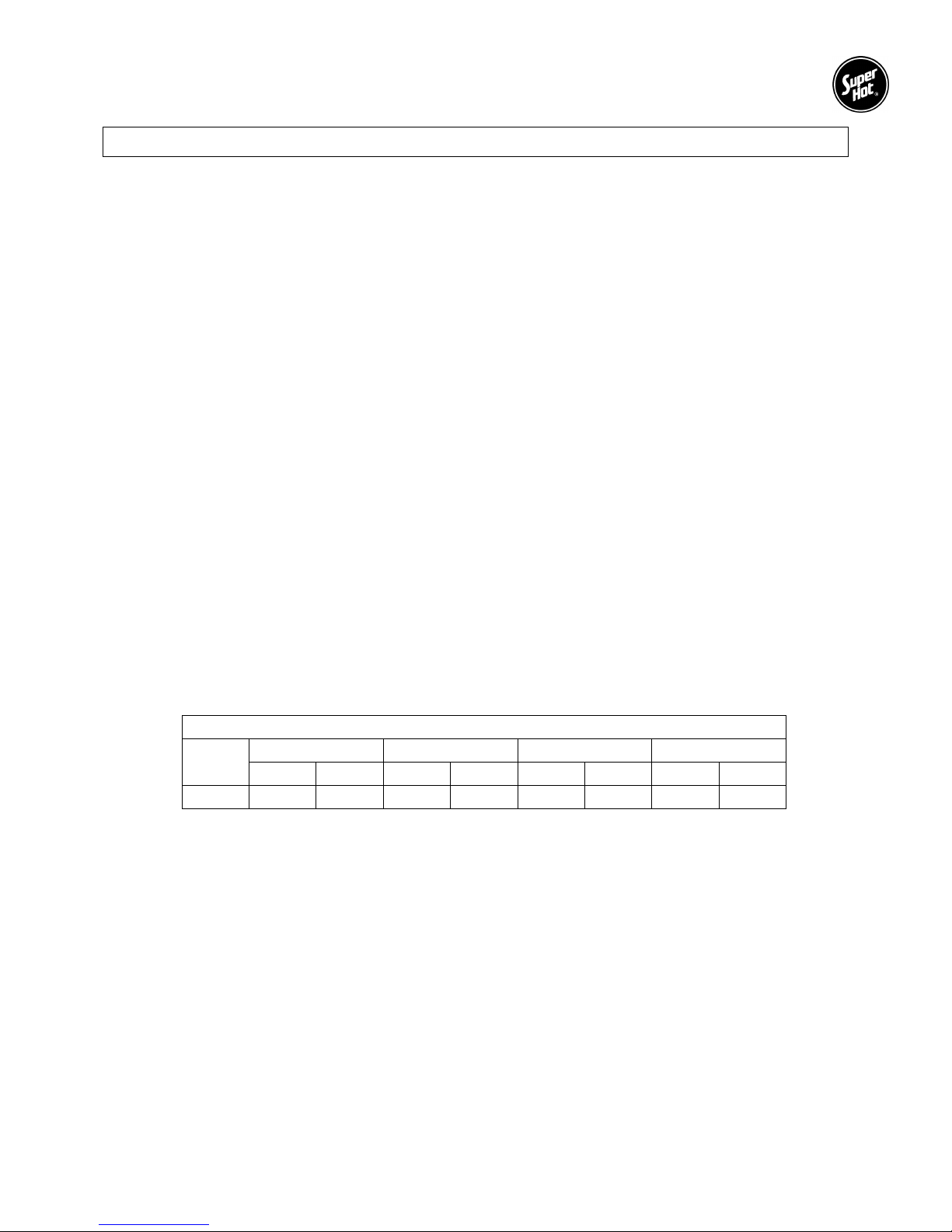
Boiler Water Flow Data
NOTE: The boiler should be properly sized for its heating application and maintain an adequate water
flow rate during operation. Significantly oversizing the boiler or decreasing boiler water flow
rate will cause excessive stage cycling and may result in premature failure of components.
Typical Water Flow Versus Pressure Drop Across Boiler
Model
Number
AAA480 41.0 3.0 27.3 1.35
AAA600 51.2 3.0 34.1 1.35
AAA720 61.4 3.0 41.0 1.35
AAA840 71.7 3.0 47.8 1.35
AAA960 81.9 3.0 54.6 1.35
AAA1080 92.2 3.0 61.4 1.35
U.S. GPM P.D. FT. U.S. GPM P.D. FT.
20°°°°F T.D. 30°°°°F T.D.
AAA1200 102.4 3.0 68.3 1.35
AAA1320 112.7 3.0 75.1 1.35
AAA1440 122.9 3.0 81.9 1.35
AAA1560 133.1 3.0 88.8 1.35
AAA1680 143.4 3.0 95.6 1.35
AAA1800 153.6 3.3 102.4 1.35
AAA1920 163.9 3.3 109.2 1.5
AAA2040 174.1 3.5 116.1 1.6
AAA2160 184.3 3.5 122.9 1.6
AAA2280 194.6 3.8 129.7 1.7
AAA2400 204.8 3.8 136.5 1.7
AAA2495 212.9 3.8 142.0 1.7
AAA2640 225.3 3.8 150.2 1.7
AAA2760 235.5 3.8 157.0 1.7
AAA2880 245.8 3.8 163.9 1.7
AAA3000 256.0 3.8 170.7 1.7
3
AAA Series Gas Boiler – Installation and Service Manual
ABOUT OUR MANUALS
Your Super Hot boiler has been provided with the following manuals:
• User's Information Manual - This manual is intended for the owner or user of the boiler and provides
information on routine operation and maintenance, and emergency shutdown.
• Installation and Service Manual - This manual must only be used by a qualified heating installer,
service technician or gas supplier. Installation or service by anyone unqualified to do so may result
in severe personal injury, death or substantial property damage.
• BTC Series Controller Manual - This manual must only be used by a qualified heating installer or
service technician. BTC Series Controller Manual contains detailed information on controller
operation applicable to single stage and two stage AAA boilers.
All manuals should be kept in the envelope provided and affixed adjacent to the boiler so that they are
readily available for future reference.
Lighting Instructions Section 1
1.1 SAFETY INSTRUCTIONS
WARNING
If you do not follow these instructions exactly, a fire or explosion may result causing property
damage, personal injury or loss of life.
A. BEFORE LIGHTING smell all around the
boiler area for gas. Be sure to smell next to
the floor because some gas is heavier than
air and will settle on the floor.
WHAT TO DO IF YOU SMELL GAS
• Do not try to light any appliance.
• Do not touch any electrical switch; do not
use any phone in your building.
• Immediately call your gas supplier from a
neighbor's phone. Follow the gas
supplier's instructions.
• If you cannot reach your gas supplier, call
the fire department.
B. Use only your hand to push in or turn the gas
control knob. Never use tools. If the knob will
not push in or turn by hand, don't try to repair
it, call a qualified service technician. Force or
attempted repair may result in a fire or
explosion.
C. Do not use this boiler if any part has been
under water. Immediately call a qualified
service technician to inspect the appliance and
to replace any part of the control system and
any gas control which has been under water.
1.2 LIGHTING INSTRUCTIONS
Your boiler is equipped with an intermittent electronic ignition system which will automatically light a pilot
burner. After the module senses the pilot flame, the main gas valve and redundant valve will open,
allowing the pilot burner to ignite the main burner. The following section provides instructions for lighting
the boiler.
4
AAA Series Gas Boiler – Installation and Service Manual
1.3 LIGHTING INSTRUCTIONS FOR INTERMITTENT ELECTRONIC IGNITION
WITH NON-COMBINATION GAS VALVE
This boiler is equipped with an ignition device, which automatically lights the pilot. Do not try to light the
pilot by hand. Before turning on the electrical power switch, be sure all gas supply lines are purged of air
and power supply to control is the correct voltage.
If the pilot or main burners are not lit or the control system is locked-out due to flame failure, close the
main and pilot gas shut-off valves and call your service technician or gas supplier. If you smell gas, STOP!
Follow “A” in the safety instructions in Section 1.1.
Check Control Operation
1. STOP! Read the safety instructions in Section
1.1.
2. For 100% shut off check, close main and pilot
manual gas shut off valves, turn off all electric
power to the boiler and wait for five minutes
to clear out any gas.
3. Then smell for gas, including near the floor. If
you smell gas, STOP! Follow safety
instructions in Section 1.1. If you don’t smell
gas, go to the next step.
4. Set the thermostat above room temperature
and turn on all electric power to the boiler to
energize the electronic ignition and pilot
valve. After a few seconds, control system
should “lockout” and all functions are off.
5. To take the control system out of “lockout”
either press the reset button or interrupt
power to the boiler, depending on the boiler
controller. Some controllers will retry ignition
automatically after 5 minutes lockout.
Start System
1. Turn on the main and pilot manual gas shutoff valves.
2. Set thermostat above room temperature and
turn on all electrical power to the boiler.
3. Once the pilot flame is proven, the controller
opens the main burner gas valves. The pilot
flame will ignite the gas as it exits the main
burner ports.
4. Set thermostat to the desired setting to put
system back in service.
Relight Operation
Five minutes complete shut off period is required
before attempting to relight the boiler. To relight
the boiler, follow the Start System procedure
(above).
To turn off gas to boiler or emergency shut-off
Follow Section 1.4
1.4 TO TURN OFF GAS TO THE BOILER OR EMERGENCY SHUT-OFF
WARNING
Should boiler overheat, or the gas supply fail to shut off, do not turn off or disconnect the
electrical supply to the circulating pump. Instead, shut off the gas supply at a location external
to the boiler.
1. Set the thermostat to the lowest setting.
2. Turn all electrical power to the boiler off.
3. Remove control access panel on the boiler if necessary.
4. Close the main and pilot manual gas shut off valves. The valve is "OFF" when handle is perpendicular
to the direction of gas flow.
5. Replace control access panel if necessary.
5
AAA Series Gas Boiler – Installation and Service Manual
Installation Instructions Section 2
2.1 RECEIVING
INSPECT SHIPMENT FOR POSSIBLE DAMAGE. All goods are carefully manufactured, inspected,
checked and packed by experienced workers. The manufacturer's responsibility ceases upon delivery of
goods to the carrier in good condition. Any claims for damage, shortage in shipment or non-delivery must
be filed immediately against the carrier by the consignee.
Use care when receiving and unpacking the boiler. Dropping the boiler may cause damage and prevent
safe and proper operation.
2.2 INSTALLATION CODES AND REQUIREMENTS
All applicable national, provincial/state, and local codes, laws, regulations, and ordinances must be
followed. They expand on and take precedence over any recommendations in this booklet. Authorities
having jurisdiction shall be consulted before installations are made.
In Canada, the installation must conform to the requirements of the authority having jurisdiction or, in the
absence of such requirements, to the CAN/CSA B149 Installation Codes (current edition). All electrical
wiring must be in accordance with the Canadian Electrical Code, CSA C22.1 Part 1 (current edition) and
applicable local codes.
In the United States of America, the installation must conform to the requirements of the authority having
jurisdiction or, in the absence of such requirements, to the National Fuel Gas Code, ANSI Z223.1 (current
edition). All electrical wiring must be in accordance with the National Electrical Code, ANSI/NFPA 70
(current edition) and applicable local codes.
Where required by the authority having jurisdiction, follow the Standard for Controls and Safety Devices
for Automatically Fired Boilers, ANSI/ASME CSD-1 (current edition).
2.3 LOCATION
AAA boilers are intended for indoor installation only. Observe the following minimum clearances from the
boiler to combustible materials:
Clearances to Combustible Materials
Model
AAA
Sides Rear Top Front (service)
in mm in mm in mm in mm
6 153 6 153 36 915 40 1016
• Maintain a clearance of 6" (153 mm) from draft hood and the flue pipe in any direction.
• Allow ample space for boiler inlet and outlet connections, and gas connection.
• Boiler must be installed on a stable and level foundation.
• AAA Series boilers must be installed on a Non-Combustible floor.
• A hot water boiler installed above radiation level must be provided with a low water cutoff
device at the time of boiler installation.
• This boiler must be installed such that gas ignition system components are protected from water
(dripping, spraying, rain, etc.) during appliance operation and service.
6

AAA Series Gas Boiler – Installation and Service Manual
2.4 GAS SERVICE PIPING
The boiler and its gas connection must be leak tested before placing the boiler in operation. The gas
controls furnished are suitable for a maximum operating gas pressure of 1/2 psi (14 inches water column).
The boiler and its individual shutoff valve must be disconnected from the gas supply piping system during
any pressure testing of that system at test pressures in excess of 1/2 psig (14 inches water column).
The boiler must be isolated from the gas supply piping system by closing its individual manual shutoff
valve during any pressure testing at test pressures equal to or less than 1/2 psig (14 inches water
column).
A manual main shut-off valve should be installed in the gas line outside the boiler jacket and as required in
Section 2.2. The valve should be readily accessible for turning on and off.
A drip pocket or sediment trap should be installed in the gas supply line upstream of the gas controls and
as close to the boiler as possible (example shown in Figure 7 in Section 6).
Some pressure regulators or pressure regulating sections of gas valves are provided with an integral vent
limiter and threaded connection. A bleed or gas relief line should be connected to it and piped to the
outdoors.
The pipe compound used should be resistant to the action of liquefied petroleum gases. Check for gas
leaks in piping before placing the boiler in operation by using a soap and water solution. DO NOT USE
AN OPEN FLAME.
INSTALLER MUST IDENTIFY EMERGENCY SHUT-OFF DEVICES.
All piping and fittings must be installed as per codes in Section 2.2.
2.5 AIR SUPPLY FOR COMBUSTION AND VENTILATION
A sufficient air supply MUST be provided to this boiler. Air openings to the boiler room provide the air for
combustion, flue gas dilution and ventilation and are always required, regardless whether the air is taken
from inside or outside. The air opening size and location (as well as other air supply and venting
considerations) must conform to Section 2.2.
The boiler room must never be under a negative pressure. Always provide air openings sized not only to
the dimensions required for the total input of all fuel-fired appliances in the boiler space, but also to handle
the air movement rate of any exhaust fans or air movers using air from the building or space.
The venting terminations must always be kept clear of obstructions (i.e. snow, ice, etc.). Louvers and
grilles used in the air supply and ventilation system should be kept clear of any dust, dirt, or debris which
will block proper air flow.
2.6 CORROSIVE ATMOSPHERES
If a gas boiler is to be installed near a corrosive or potentially corrosive air supply, the boiler should be
isolated from it and outside air should be supplied as recommended in Section 2.5.
Chemical vapors from products containing chlorine or fluorine must be avoided. Even though these
chemicals may be safe to breathe, corrosive substances can become liberated when passed through a
gas flame. Even at low concentrations, these chemicals can significantly contaminate the air supply and
shorten the life of any gas burning appliance. The following is a list of some of the products which should
be avoided:
• bleaches and chlorinated cleaning products
• paints and sprays
• water softeners (calcium or sodium chloride)
• leaking refrigeration equipment
• freon from common aerosol dispensers
These chemicals are especially common near swimming pools, beauty shops, dry cleaning
establishments, laundry areas, workshops, and garages. The warranty is void when failure is due to
corrosion.
7

AAA Series Gas Boiler – Installation and Service Manual
2.7 VENTING
The responsibility of providing a suitable vent of adequate draft capacity and in good usable condition is
that of the gas fitter/installer. Interference with the air supply for the boiler shall be prohibited.
Vent installation and type of gas vent or vent connector MUST follow all applicable national,
provincial/state, and local codes, laws, regulations, and ordinances as described in Section 2.2.
For boilers for connection to gas vents or chimneys, vent installations shall be in accordance with Part 7,
Venting of Equipment, of the National Fuel Gas Code, ANSI Z223.1 or Section 7, Venting Systems and Air
Supply for Appliances, of the CAN/CGA B149, Installation Codes, or applicable provisions of the local
building codes.
The venting shall be supported as required by applicable code(s). Horizontal runs shall slope upward not
less than ¼ inch per foot (21 mm/m) from the boiler to the vent terminal.
This unit must be installed with the factory supplied draft hood in place. The draft hood is a safety device
designed to control chimney drafts that might affect combustion or blow out the pilot. The draft hood
supplied with the boiler must not be altered. The minimum skirt height as indicated on the draft hood must
be maintained.
Vent connectors serving the boiler must not be connected into any portion of mechanical draft systems
operating under positive pressure.
Vent Terminal Information
The minimum distance from the termination of a vent terminal to adjacent public walkways, adjacent
buildings, operable windows and building openings shall be not less than those values specified in the
National Fuel Gas Code, ANSI Z223.1 and/or CAN/CGA Installation Codes.
For proper operation, the vent terminal must be kept free of snow and other debris at all times.
To prevent discoloration and degradation of building materials by flue gases and flue gas condensation,
ensure that the vent terminal is installed clear of nearby obstacles. In all cases, installation shall be in
accordance with code.
Maintain a minimum clearance of 4 feet (1.22 m) horizontally, and in no case above or below, unless a 4
foot (1.22 m) clearance is maintained from electric meters, gas meters, regulators and relief equipment.
Removal of an Existing Boiler
When an existing boiler is removed from a common venting system, the common venting system is likely
to be too large for proper venting of the appliances connected to it.
At the time of removal of an existing boiler, the following steps shall be followed with each appliance
remaining connected to the common venting system placed in operation, while the other appliances
remaining connected to the common venting system are not in operation.
a) Seal any unused openings in the common venting system.
b) Visually inspect the venting system for proper size and horizontal pitch and determine there is no
blockage or restriction, leakage, corrosion and other deficiencies which could cause an unsafe
condition.
c) Insofar as is practical, close all building doors and windows and all doors between the space in which
the appliances remaining connected to the common venting system are located and other spaces of
the building. Turn on clothes dryers and any appliance not connected to the common venting system.
Turn on any exhaust fans, such as range hoods and bathroom exhausts, so they will operate at
maximum speed. Do not operate a summer exhaust fan. Close fireplace dampers.
d) Place in operation the boiler being inspected. Follow the lighting instructions. Adjust the thermostat
so the boiler will operate continuously.
e) Test for spillage at the draft hood relief opening after 5 minutes of main burner operation. Use the
flame of a match or candle, or smoke from a cigarette, cigar or pipe.
8
AAA Series Gas Boiler – Installation and Service Manual
f) After it has been determined that each appliance remaining connected to the common venting system
properly vents when tested as outlined above, return doors, windows, exhaust fans, fireplace dampers
and any other gas burning appliance to their previous conditions of use.
g) Any improper operation of the common venting system should be corrected so the installation
conforms with the National Fuel Gas Code, ANSI Z223.1 and/or CAN/CGA Installation Codes. When
re-sizing any portion of the common venting system, the common venting system should be resized to
approach the minimum size as determined using the appropriate tables in Part 11 of the National Fuel
Gas Code, ANSI Z223.1 and/or CAN/CGA Installation Codes.
2.8 BOILER PIPING SYSTEM
The boiler piping system of a hot water boiler connected to heating coils located in air handling units
where they may be exposed to refrigerated air circulation must be equipped with flow control valves or
other automatic means to prevent gravity circulation of the boiler water during the cooling cycle.
The boiler, when used in connection with a refrigeration system, must be installed so the chilled medium is
piped in parallel with the boiler with appropriate valves to prevent the chilled medium from entering the
boiler.
2.9 CORROSION PREVENTION (INTERNAL)
The use of oxygen barrier tubing is recommended to protect the system and its components (e.g. pump)
from corrosion. Should your system include "non-oxygen barrier” tubing please contact the factory or a
heating professional for recommendations.
If freeze protection is required, use an inhibited propylene glycol solution which is specifically designed for
hydronic heating systems and always maintained at a neutral pH (e.g. Fernox Alphi-11 or equivalent).
Follow the supplier’s instructions for proper use and maintenance. Do not use automotive antifreeze.
Some types of chemical additives can cause problems such as accelerated corrosion and result in
premature failure of the boiler heat exchanger and/or system components, especially when not properly
used or maintained. Corrosion is a preventable condition and is not covered by the product warranty.
2.10 SYSTEM OPERATING REQUIREMENTS
WARNING
If you do not follow these instructions exactly, a fire or explosion may result causing property
damage, personal injury or loss of life.
Avoid unnecessary replenishment of system water. It can allow oxygen to enter the system and cause
serious corrosion problems. As well, minerals dissolved in the water supply will precipitate when heated;
minerals preferentially deposit in the heat exchanger. Do not draw water from the heating system for
cleaning, flushing, etc.
Super Hot AAA series boilers are designed for use in closed loop systems and are not intended for open
systems, as in heating pool water or systems where water is constantly replenished. Operating the boiler
in an open system will result in premature failure of the heat exchanger. Super Hot boilers may be used
to heat water in open systems indirectly by installing a heat exchanger, such as the Super Hot C-Coil, to
separate open and closed systems.
Heating systems with low temperature return water may cause flue gas moisture to condense on the boiler
heat transfer surfaces, causing corrosion and restricting flue gas flow. Also, low temperature return water
may overcool the flue gases, resulting in reduced vent suction. These are natural phenomena and are
independent of the boiler design. As a guide to avoiding such corrosion and draft problems, it is
imperative that the return water be not less than 135°F (57°C).
AAA SERIES BOILERS MUST ALWAYS BE USED WITH FORCED SYSTEM CIRCULATION.
9

AAA Series Gas Boiler – Installation and Service Manual
2.11 PRESSURE RELIEF VALVE
A pressure relief valve is supplied as standard equipment. The pressure relief valve is extra protection
against damage that could be caused by malfunctioning controls or excessive water pressure. If a
pressure relief valve is not used, the warranty is void.
The pressure relief valve should be installed on the boiler outlet with its spindle vertical. The connection
between the boiler and the relief valve must have at least the area of the valve inlet.
A discharge pipe should be used. The discharge pipe outlet should be positioned over a suitable drain and
so arranged that there will be no danger of being scalded. The discharge pipe must pitch down from the
pressure relief valve and should be no smaller than the outlet of the valve. The end of the discharge pipe
should not be concealed or threaded and should be protected from freezing. Extensive runs, traps or
bends could reduce the capacity of the pressure relief valve.
No valve of any type should be installed between the pressure relief valve and unit or in the discharge
pipe. The pressure relief valve is a code requirement. Field installation of the relief valve must be
consistent with the ANSI/ASME Boiler and Pressure Vessel Code, Section IV.
Avoid contact with the hot water discharged to prevent personal injury.
2.12 ELECTRICAL WIRING
WARNING
Risk of electric shock. This boiler may be connected to more than one electrical circuit. Turn off
all electric power supply circuits at the electrical service panel or supply source. Failure to do
so may result in severe personal injury or death.
All electrical wiring must conform to the requirements in Section 2.2.
Run a separate circuit from the electrical service panel through a fused disconnect switch to the boiler.
This boiler must be electrically bonded to ground in accordance with the requirements of the authority
having jurisdiction or, in the absence of such requirements, with the National Electrical Code, ANSI/NFPA
70 (current edition) and and/or the Canadian Electrical Code, CSA C22.1 Part 1 (current edition). Field
wiring shall conform to Section 2.2 and to the temperature limitations of Type T [63°F (35°C) rise] or
better.
Make field connections as shown in the wiring diagrams provided with this manual or on the sticker placed
on the inside of the door panel of the boiler.
2.13 BTC SERIES CONTROLLER WIRING
The BTC series controller is supplied as standard option with two stage and single stage boilers; it is not
supplied with boilers equipped with a full modulating gas valve. For convenience, the BTC series controller
is factory wired to terminal block TB4 and ready for field wiring connections. The field wiring to TB4 is
determined based on the operating mode selected (i.e. mode 1 to 6), the heating application and the
piping arrangement (i.e. parallel or primary/secondary). Refer to Figure 1 for the wiring diagram for each
mode. For a detailed explanation of the modes and controller operation, refer to the BTC Series
Controller Manual.
10

AAA Series Gas Boiler – Installation and Service Manual
Field wiring to terminal block TB4
Figure 1 – Field wiring to terminal block TB4
11
 Loading...