

Super Hot BT Series, 6BT, 9BT, 12BT, 15BT Installation And Service Manual
...
g
(
)
INSTALLATION AND SERVICE MANUAL
BT SERIES ELECTRIC BOILER
FOR HYDRONIC HEATING APPLICATIONS
6 kW to 54 kW, 208 Vac to 600 Vac, Sin
WARNING
Risk of electric shock. This unit may be connected to more than one
electrical circuit. Disconnect all electrical circuits before servicing.
IMPORTANT
• The boiler must be installed in accordance with all applicable national, provincial/state,
and local codes, laws, regulations, and ordinances.
• This manual must be left with owner and should be located adjacent to the boiler for
reference.
• Ensure boiler is full of water before turning on electricity. Elements will burn out
immediately without water in the boiler.
• A boiler installed above radiation level (or as required by an Authority having
jurisdiction) must be provided with a low-water cut-off device at the time of boiler
installation.
• Overcurrent protection between the power supply and the boiler must be provided in
accordance with the related national and/or local codes.
• Always ensure power is turned off before servicing.
• Electrical wiring or internal controls must be serviced by a qualified electrician. Any
adjustment of the internal controls must be performed by a qualified service technician.
le or Three Phase
Post these instructions in a visible place.
DATE OF INSTALLATION :
INSTALLED BY :
PHONE :
Featuring our newest
“BiTronic Control System”
Manufactured by
Allied Engineering Company
Manufacturers of Gas and Electric Boilers, Stainless Steel Tanks, Tankless Coils, Electric Boosters
94 Riverside Drive, North Vancouver, B.C. V7H 2M6 • Telephone (604) 929-1214 • FAX (604) 929-5184
PN4152451
Division of E-Z-Rect Manufacturing Ltd.
Branches: Calgary • Edmonton • Toronto
OPTIONAL
BT Series Electric Boilers – Installation, Operating and Maintenance Instructions
Dimensions and Specifications Section 1
1.1 TECHNICAL SPECIFICATIONS
Maximum Operating Pressure: 90 p.s.i.
Maximum Operating Water Temperature: 210ºF
Water Capacity in Boiler: 6.6 US Gallons
Inlet and Outlet Pipe Size: 1 1/4” NPT
Controller Pump Switch Capacity: 5A Maximum
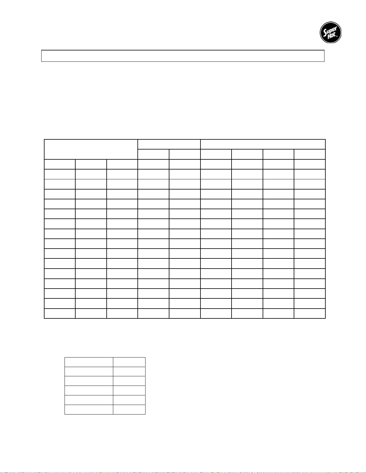
Table 1: Super Hot BT Series Electric Boiler Specifications. (Flange Type Elements)
Super Hot
BT Series Electric Boilers
Single Phase Three Phase
208 Vac 240 Vac 208 Vac 240 Vac 480 Vac 600 Vac
Model kW Btu/Hr Amp Amp Amp Amp Amp Amp
6BT 6 20,474 28.9 25.0 16.7 14.4 7.2 5.8
9BT 9 30,708 43.3 37.5 25.0 21.6 10.8 8.7
12BT 12 40,848 57.7 50.0 33.3 28.8 14.4 11.5
15BT 15 51,185 72.1 62.5 41.6 36.0 18.0 14.4
18BT 18 61,422 86.5 75.0
20BT 20 68,240 96.2 84.3
54.6* 47.3* 23.7* 18.9*
63.6* 55.1* 27.6* 22.0*
24BT 24 81,895 115 100 66.5 57.7 28.8 23.1
27BT 27 92,124 130 113 74.9 64.9 32.4 26.0
30BT 30 102,369 144 125 83.2 72.1 36.0 28.8
34BT 34 116,008 164 142
38BT 38 129,656 183 158
100* 87.0* 43.5* 34.8*
118* 102* 50.5* 40.4*
42BT 42 143,304 202 175 116 101 50.5 40.4
45BT 45 153,540 216 188 125 108
48BT 48 163,776 231 200
138* 119* 59.6* 47.7*
57.7* 46.2*
54BT 54 184,248 260 225 150 130 64.9 52.0
Note:
1. Other models of the BT Series Electric Boiler may be available subject to inquiry.
2. * Delta connection (unbalanced load) amperage of high leg indicated.
3. Approximate shipping weights:
Model Weight
Ŧ
6BT & 9BT 114 lb
12BT to 18BT 116 lb
20BT & 24BT 118 lb
27BT to 38BT 122 lb
42BT to 54BT 126 lb
Ŧ
Add 45 lb for package models
2
BT Series Electric Boilers – Installation, Operating and Maintenance Instructions
1.2 WATER TEMPERATURE RISE vs FLOW RATE
NOTE: The boiler should be properly sized for its heating application and maintain an adequate water
flow rate during operation. Significantly oversizing the boiler or decreasing boiler water flow
rate will cause excessive stage cycling and result in premature failure of the contactors.
Water flow rate vs temperature rise formulas in US gallons per minute (GPM) and liters per minute (LPM):
GPM =
6.94 x kW 14.6 x kW
Temp. Rise (°F)
LPM =
Temp. Rise (°C)
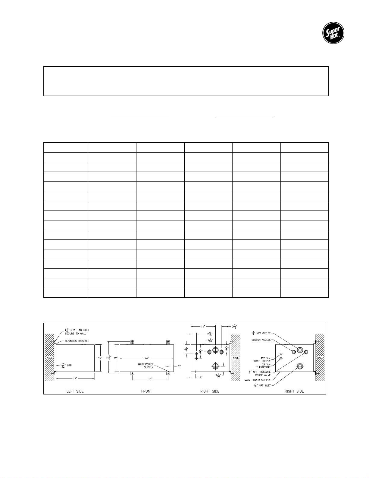
Table 2: Water Temperature Rise vs Flow Rate in GPM (LPM)
Model KW
10°F (5.6°C) 20°F (11°C) 30°F (17°C) 40°F (22°C)
6BT 6 4.2 (16) 2.1 (8) 1.4 (5) 1.0 (4)
9BT 9 6.2 (23) 3.1 (12) 2.1 (8) 1.6 (6)
12BT 12 8.3 (31) 4.2 (16) 2.8 (10) 2.1 (8)
15BT 15 10.4 (39) 5.2 (20) 3.5 (13) 2.6 (10)
18BT 18 12.5 (47) 6.2 (24) 4.2 (15) 3.1 (12)
20BT 20 13.9 (52) 6.9 (27) 4.6 (17) 3.5 (13)
24BT 24 16.6 (63) 8.3 (32) 5.5 (21) 4.2 (16)
27BT 27 18.7 (70) 9.4 (36) 6.2 (23) 4.7 (18)
30BT 30 20.8 (78) 10.4 (40) 6.9 (26) 5.2 (20)
34BT 34 23.6 (89) 11.8 (45) 7.9 (29) 5.9 (23)
38BT 38 26.4 (99) 13.2 (50) 8.8 (33) 6.6 (25)
42BT 42 29.1 (109) 14.6 (56) 9.7 (36) 7.3 (28)
45BT 45 31.2 (117) 15.6 (60) 10.4 (39) 7.8 (30)
48BT 48 33.3 (125) 16.6 (64) 11.1 (41) 8.3 (32)
54BT 54 37.5 (141) 18.7 (72) 12.5 (46) 9.4 (36)
1.3 GENERAL DIMENSIONS
Figure 1 – General Dimensions
3
BT Series Electric Boilers – Installation, Operating and Maintenance Instructions
Installation Instructions Section 2
2.1 RECEIVING
INSPECT SHIPMENT FOR POSSIBLE DAMAGE. All goods are carefully manufactured, inspected,
checked and packed by experienced workers. The manufacturer's responsibility ceases upon delivery of
goods to the carrier in good condition. Any claims for damage, shortage in shipment or non-delivery must
be filed immediately against the carrier by the consignee.
2.2 INTRODUCTION
Super Hot Electric Boilers are controlled by a three-stage electronic temperature controller. The
controller controls the boiler water temperature with three stages and turns stages on based on the
heating demand, time delay, and the preset boiler outlet water temperature. The controller also can
control 120Vac circulating pumps rated up to 5A or 600VA. When the thermostat calls for heat, the
controller will operate the boiler to regulate the water temperature at a pre-selected setpoint. The system
pump is on whenever there is a thermostat calling for heat.
Multi-stage electric boilers have a number of advantages over conventional on/off single stage boilers.
Instead of switching on/off all heating elements using sequencers, each stage of a multi-stage boiler is
controlled directly by the controller to minimize both temperature fluctuations and reduce the number of
on/off operations of the contactors/heating elements. The on/off times of each of the stages are
separated by a pre-determined minimum time interval to avoid a surge in line current. The average “cycle
time” of each of the heating elements shall be greatly increased. This ensures better temperature
stability, extends the life of the boiler and increases energy efficiency.
2.3 BOILER LOCATION
The boiler is intended for indoor installation only and must not be subjected to water spray or leakage. It
may be installed in an enclosed space and attached directly to a combustible surface. Allow ample space
around the boiler to ensure all connections and controls are readily accessible. The minimum required
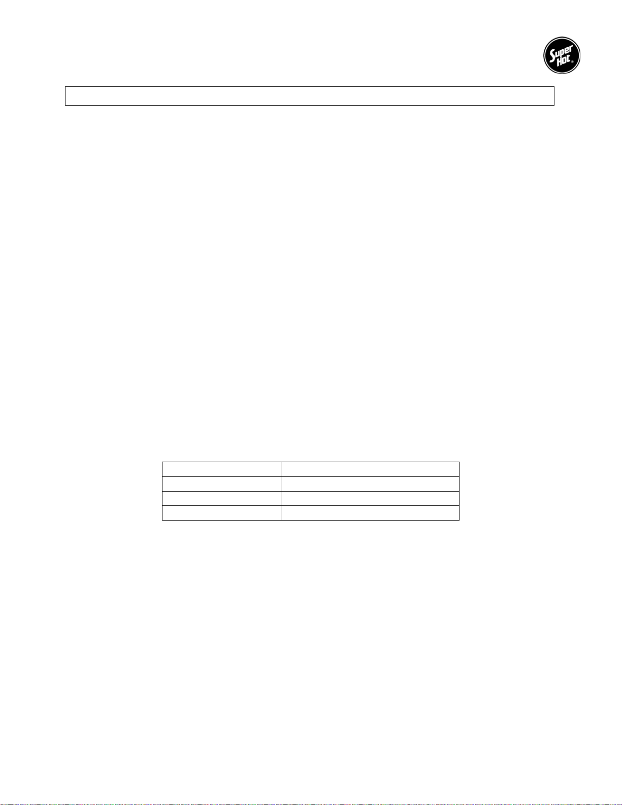
clearances for service are shown in the following table:
Minimum Clearance Provides service access for
left side = 18 inches elements
right side = 12 inches plumbing connections
front = 12 inches electrical components and fuses
It may be preferred to locate the boiler close to the electrical supply panel.
4

BT Series Electric Boilers – Installation, Operating and Maintenance Instructions
2.4 WALL MOUNTING
CAUTION: Failure to correctly position the boiler may result in element burn out.
This boiler must be installed using the attached wall mounting brackets. It is critical that the boiler be
installed level and oriented as shown in Figure 2 (below). When correctly positioned, the front panel is
vertical and the 1 1/4”NPT outlet connection is directly above the 1 1/4”NPT inlet connection.
The wall mounting brackets on the boiler feature a “key-hole” opening suitable to fit over the head of two
previously installed 5/16” lag screws. The key-hole openings are located on 16” centers (i.e. standard
stud spacing) on the top side of the hangers. The lag screws must be suitably anchored to safely support
the weight of the boiler including water content, piping and wiring.
2.5 PIPING
The recommended piping arrangement is shown in Figure 2. Attach pump, expansion tank, drain valve,
pressure relief valve, air vent, pressure temperature gauge and flow switch (as required). Air vents
should be installed at points just upstream from all drops in elevation of the piping system (high points).
A boiler installed above radiation level, or as required by an authority having jurisdiction, must be
provided with a low-water cut-off device at the time of boiler installation.
Figure 2 – Piping Arrangement
5
 Loading...