

Super Hot 6MSE, 9MSE, 12MSE, 15MSE, 18MSE Installation And Service Manual
...
INSTALLATION AND SERVICE MANUAL
6 kW to 54 kW, 208 Vac to 600 Vac, Single or Three Phase
(OPTIONAL)
MINI-STAR® ELECTRIC BOILER
Models 6MSE to 54MSE for Hydronic Heating
WARNING
Risk of electric shock. This unit may be connected to more than one
electrical circuit. Turn off all electrical supply circuits before servicing.
IMPORTANT
• The boiler must be installed in accordance with all applicable national, provincial/state,
and local codes, laws, regulations, and ordinances.
• This manual must be left with owner and should be located adjacent to the boiler for
reference.
• Ensure boiler is full of water before turning on electricity. Elements will burn out
immediately without water in the boiler.
• A boiler installed above radiation level (or as required by an Authority having
jurisdiction) must be provided with a low-water cut-off device at the time of boiler
installation.
• Overcurrent protection between the power supply and the boiler must be provided in
accordance with the related national and/or local codes.
• Always ensure power is turned off before servicing.
• Electrical wiring or internal controls must be serviced by a qualified electrician. Any
adjustment of the internal controls must be performed by a qualified service
technician.
Post these instructions in a visible place.
DATE OF INSTALLATION :
INSTALLED BY :
PHONE :
Featuring the
BC-1 Controller
with Outdoor Reset and DHW Override
Manufactured by
Allied Engineering Company
Manufacturers of Gas and Electric Boilers, Heat Exchangers, Electric Boosters, Indirect Tanks
94 Riverside Drive, North Vancouver, B.C. V7H 2M6 • Telephone 604-929-1214 • www.alliedboilers.com
PN4330651
Division of E-Z-Rect Manufacturing Ltd.
Branches: Calgary • Edmonton • Toronto • Denver
MSE Series Electric Boilers – Installation and Service Manual
Dimensions and Specifications Section 1
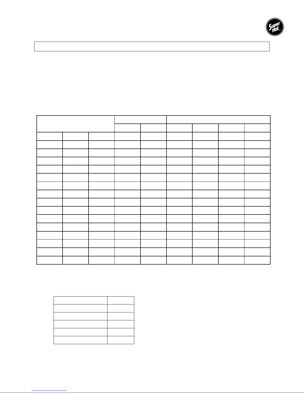
1.1 TECHNICAL SPECIFICATIONS
Maximum Operating Pressure: 90 p.s.i.
Maximum Operating Water Temperature: 210ºF
Water Capacity in Boiler: 6.6 US Gallons
Inlet and Outlet Pipe Size: 1 1/4” NPT
Controller Pump Switch Capacity: 5A Maximum
Table 1: Super Hot MSE Series Electric Boiler Specifications. (Flange Type Elements)
Super Hot
MSE Series Electric Boilers
Single Phase Three Phase
208 Vac 240 Vac 208 Vac 240 Vac 480 Vac 600 Vac
Model kW Btu/Hr Amp Amp Amp Amp Amp Amp
6MSE 6 20,474 28.9 25.0 16.7 14.4 7.2 5.8
9MSE 9 30,708 43.3 37.5 25.0 21.6 10.8 8.7
12MSE 12 40,848 57.7 50.0 33.3 28.8 14.4 11.5
15MSE 15 51,185 72.1 62.5 41.6 36.0 18.0 14.4
18MSE 18 61,422 86.5 75.0
20MSE 20 68,240 96.2 84.3
54.6* 47.3* 23.7* 18.9*
63.6* 55.1* 27.6* 22.0*
24MSE 24 81,895 115 100 66.5 57.7 28.8 23.1
27MSE 27 92,124 130 113 74.9 64.9 32.4 26.0
30MSE 30 102,369 144 125 83.2 72.1 36.0 28.8
34MSE 34 116,008 164 142
38MSE 38 129,656 183 158
100* 87.0* 43.5* 34.8*
118* 102* 50.5* 40.4*
42MSE 42 143,304 202 175 116 101 50.5 40.4
45MSE 45 153,540 216 188 125 108
48MSE 48 163,776 231 200
138* 119* 59.6* 47.7*
57.7* 46.2*
54MSE 54 184,248 260 225 150 130 64.9 52.0
Note:
1. Other models of the MSE Series Electric Boiler may be available subject to inquiry.
2. * Delta connection (unbalanced load) amperage of high leg indicated.
3. Approximate shipping weights:
Model Weight Ŧ
6MSE & 9MSE 114 lb
12MSE to 18MSE 116 lb
20MSE & 24MSE 118 lb
27MSE to 38MSE 122 lb
42MSE to 54MSE 126 lb
Ŧ
Add 45 lb for package models
2
MSE Series Electric Boilers – Installation and Service Manual
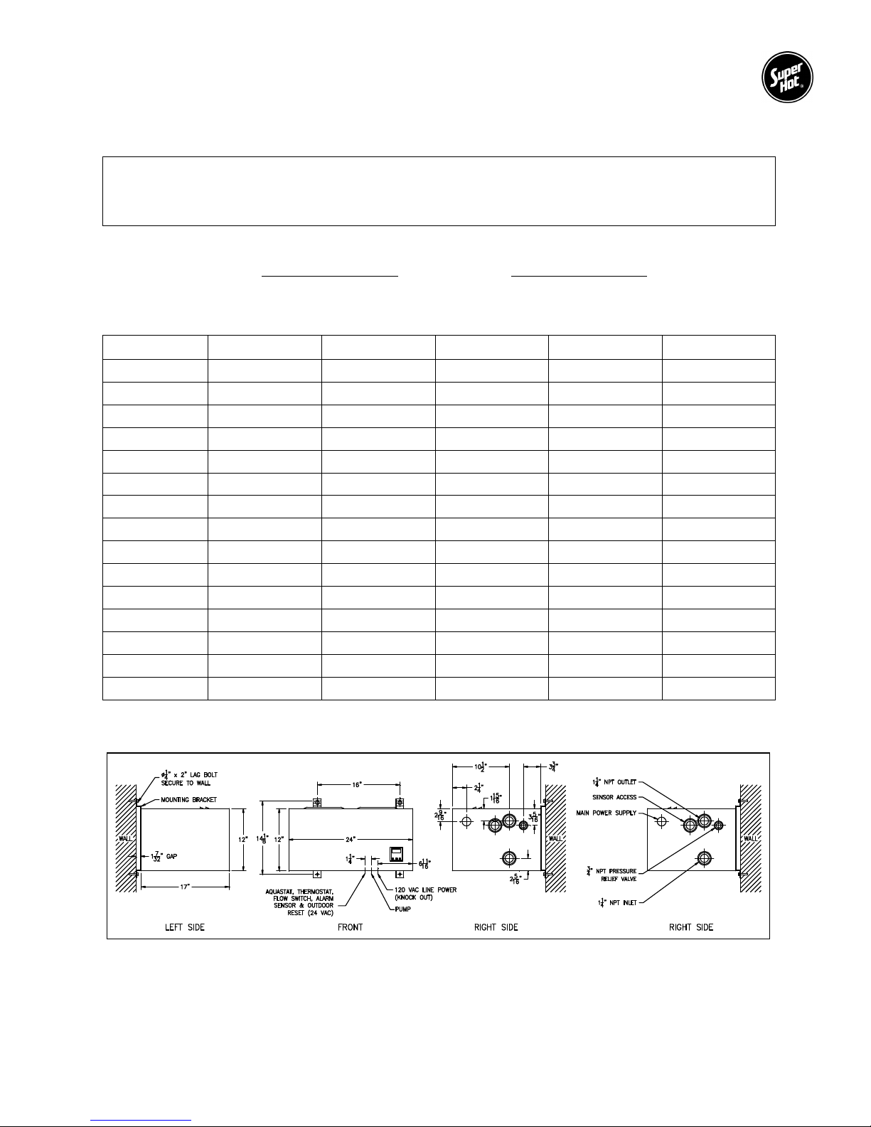
1.2 WATER TEMPERATURE RISE vs FLOW RATE
NOTE: The boiler should be properly sized for its heating application and maintain an adequate water
flow rate during operation. Significantly oversizing the boiler or decreasing boiler water flow
rate will cause excessive stage cycling and result in premature failure of the contactors.
Water flow rate vs temperature rise formulas in US gallons per minute (GPM) and liters per minute (LPM):
GPM =
6.94 x kW 14.6 x kW
Temp. Rise (°F)
LPM =
Temp. Rise (°C)
Table 2: Water Temperature Rise vs Flow Rate in GPM (LPM)
Model KW
10°°°°F (5.6°°°°C) 20°°°°F (11°°°°C) 30°°°°F (17°°°°C) 40°°°°F (22°°°°C)
6MSE 6 4.2 (16) 2.1 (8) 1.4 (5) 1.0 (4)
9MSE 9 6.2 (23) 3.1 (12) 2.1 (8) 1.6 (6)
12MSE 12 8.3 (31) 4.2 (16) 2.8 (10) 2.1 (8)
15MSE 15 10.4 (39) 5.2 (20) 3.5 (13) 2.6 (10)
18MSE 18 12.5 (47) 6.2 (24) 4.2 (15) 3.1 (12)
20MSE 20 13.9 (52) 6.9 (27) 4.6 (17) 3.5 (13)
24MSE 24 16.6 (63) 8.3 (32) 5.5 (21) 4.2 (16)
27MSE 27 18.7 (70) 9.4 (36) 6.2 (23) 4.7 (18)
30MSE 30 20.8 (78) 10.4 (40) 6.9 (26) 5.2 (20)
34MSE 34 23.6 (89) 11.8 (45) 7.9 (29) 5.9 (23)
38MSE 38 26.4 (99) 13.2 (50) 8.8 (33) 6.6 (25)
42MSE 42 29.1 (109) 14.6 (56) 9.7 (36) 7.3 (28)
45MSE 45 31.2 (117) 15.6 (60) 10.4 (39) 7.8 (30)
48MSE 48 33.3 (125) 16.6 (64) 11.1 (41) 8.3 (32)
54MSE 54 37.5 (141) 18.7 (72) 12.5 (46) 9.4 (36)
1.3 GENERAL DIMENSIONS
Figure 1 – General Dimensions
3
MSE Series Electric Boilers – Installation and Service Manual
Installation Instructions Section 2
2.1 RECEIVING
INSPECT SHIPMENT FOR POSSIBLE DAMAGE. All goods are carefully manufactured, inspected,
checked and packed by experienced workers. The manufacturer's responsibility ceases upon delivery of
goods to the carrier in good condition. Any claims for damage, shortage in shipment or non-delivery must
be filed immediately against the carrier by the consignee.
2.2 INTRODUCTION
The Super Hot Mini-Star® Electric Boiler provides convenient and comfortable hydronic heating for closed
loop systems in both residential and commercial applications. It is controlled by the BC-1 controller which
regulates the boiler water temperature using three stages, switching stages on or off based on heating
demand, PID (proportional, integral, differential) logic, and user-defined water temperature settings. The
controller is capable of controlling a 120 Vac circulating pump (rated up to 5A or 600VA) which activates
when there is a thermostat or DHW call for heat.
Using three stages to regulate the boiler water temperature has advantages over conventional on/off
single stage boilers. Instead of switching all heating elements on or off using sequencers, the BC-1
controls each stage directly to minimize temperature fluctuations, avoid surges in line current, and reduce
the number of on/off operations of the contactors and heating elements. Because the average “on/off
cycle” of each of the heating elements is greatly decreased, this ensures better temperature stability,
extends the life of the components and increases energy efficiency.
With the addition of an Outdoor Sensor to the BC-1 controller, “Outdoor Reset” can be used to increase or
decrease outlet water temperature based on changing outdoor air temperatures. This feature helps
reduce temperature swings and allows the boiler output to more closely match the actual heating load.
2.3 BOILER LOCATION
The boiler is intended for indoor installation only and must not be subjected to water spray or leakage. It
may be installed in an enclosed space and attached directly to a combustible surface. Allow ample space
around the boiler to ensure all connections and controls are readily accessible. The minimum required
clearances for service are shown in the following table:
Minimum Clearance Provides service access for
left side = 18 inches (458 mm) elements
right side = 12 inches (305 mm) plumbing connections
front = 12 inches (305 mm) electrical components and fuses
top = 10 inches (254 mm) screws for front casing panel
bottom = 10 inches (254 mm) screws for front casing panel
It may be preferable to locate the boiler close to the electrical supply panel.
Protection from Liquids
The controller and other components located within the control panel are sensitive to water and other
liquids. Measures must be taken to fully protect components on the control panel from contact with liquids.
This especially applies to overhead pipes which may leak, burst or drip condensate and cause damage.
4
MSE Series Electric Boilers – Installation and Service Manual
2.4 WALL MOUNTING
CAUTION: Failure to correctly position the boiler may result in element burn out. For example,
installing the boiler with the front casing panel facing upwards will result in element burn out.
This boiler must be installed using the attached wall mounting brackets. It is critical that the boiler be
installed level and oriented as shown in Figure 2 (below). When correctly positioned, the front panel is
vertical and the 1 1/4”NPT outlet connection is directly above the 1 1/4”NPT inlet connection.
The wall mounting brackets on the boiler feature a “key-hole” opening suitable to fit over the head of two
previously installed 5/16” lag screws. The key-hole openings are located on 16” centers (i.e. standard
stud spacing) on the top side of the hangers. The lag screws must be suitably anchored to safely support
the weight of the boiler including water content, piping and wiring.
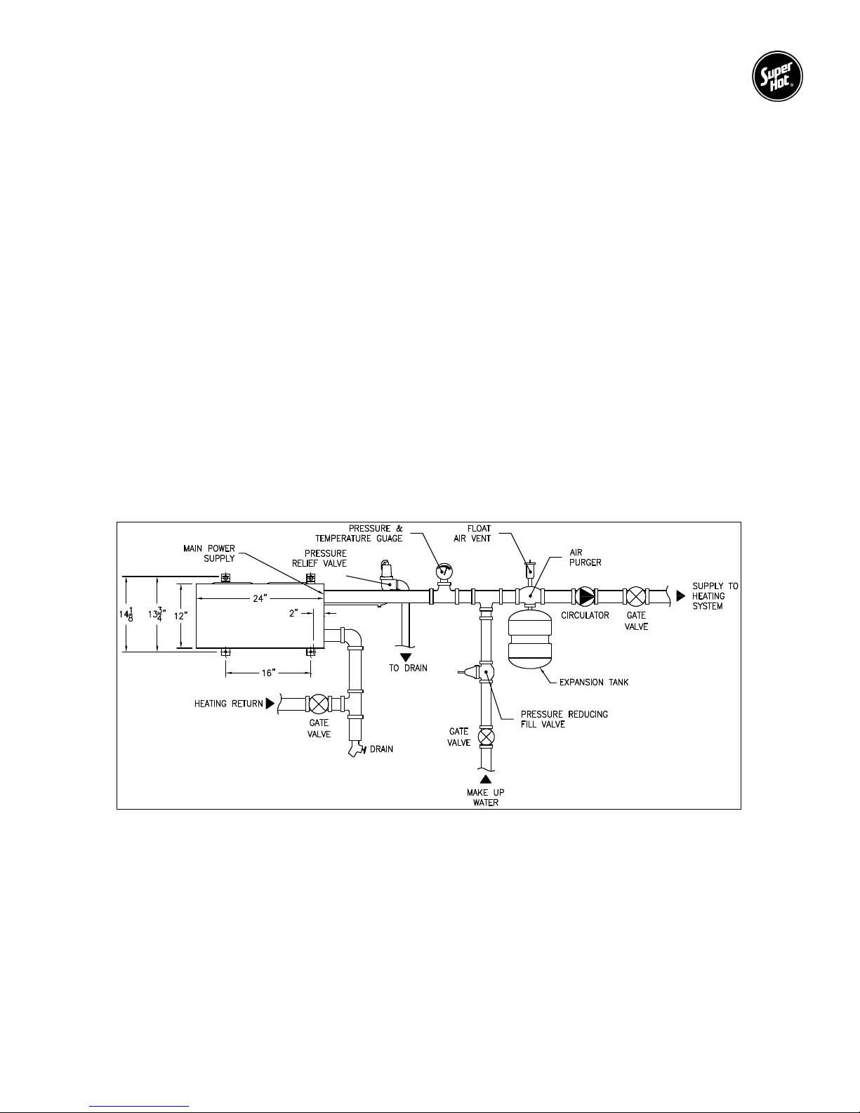
2.5 PIPING
The BC-1 controller includes six operation modes to handle various piping arrangements and applications
as specified in the BC-1 Controller Manual. The operation mode of the controller must be correctly
selected to match the piping arrangement.
A typical parallel piping arrangement is shown below in Figure 2. Attach pump, expansion tank, drain
valve, pressure relief valve, air vent, pressure temperature gauge and flow switch (as required). Air vents
should be installed at points just upstream from all drops in elevation of the piping system (high points).
A boiler installed above radiation level, or as required by an authority having jurisdiction, must be provided
with a low-water cut-off device at the time of boiler installation.
Figure 2 – Piping Arrangement
5

MSE Series Electric Boilers – Installation and Service Manual
2.6 SYSTEM OPERATING REQUIREMENTS
MSE series electric boilers are designed for use in closed loop hydronic systems and are not intended for
open systems, such as domestic hot water and pools, where water is continually replenished. Operating
the boiler in an open system will result in premature failure due to corrosion of the boiler. Electric boilers
may be used to heat water in open systems indirectly by installing a heat exchanger, such as the Super
Hot C-coil or Indirect Tank, to separate open and closed systems.
Avoid unnecessary replenishment of system water. It can allow oxygen to enter the system and cause
serious corrosion problems. As well, minerals dissolved in the water supply will precipitate when heated,
thus preferentially depositing in the boiler.
The use of oxygen barrier piping is strongly recommended to protect the system and its components from
corrosion. Chemical inhibitors are not recommended as their improper use or maintenance can cause
accelerated corrosion, and premature failure of the boiler tank and its components. If your system
includes “non-oxygen barrier tubing”, please contact the factory of your heating professional for
recommendations.
Corrosion is a preventable condition and therefore failure due to corrosion is not covered by the
Super Hot product warranty.
MSE series electric boilers must always be used with forced system circulation.
6
 Loading...