

Superformance Coupe Owner's Manual
Superformance Coupe
Owner’s Manual
Operational Guide
Warranty
First Edition
November 19, 2004

Page i
Authorized Dealer
Model Superformance Coupe
Chassis Number: SPC_______________________________
Color: ___________________________________
Stripes: ___________________________________
Purchased by: ___________________________________
Purchase Date: ___________________________________

Page ii
Superformance® Coupe
Owners Manual, Operational Guide, and Warranty
Copyright © 2003-2004 by Superformance International Inc.
Superformance® is a registered trademark of Superformance
International Inc.
Compiled by Brett Jackson, Hi-Tech Automotive, Port Elizabeth,
South Africa.
Edited by Mike Stenhouse, Second Strike, the Superformance
Owners Group, Davidson, North Carolina.
Published by Superformance International Inc., Newport News,
Virginia.
Printed in USA
November 19, 2004

Page iii
TABLE OF CONTENTS
List of Figures .................................................................. vii
Additional Information to Be Provided............................ ix
Specifications..................................................................... 1
General Specifications .....................................................................1
Chassis...................................................................................................1
Body.......................................................................................................2
Front suspension....................................................................................2
Rear suspension .....................................................................................2
Steering..................................................................................................2
Pedal box................................................................................................2
Brakes ....................................................................................................2
Cooling...................................................................................................2
Exhaust system.......................................................................................4
Interior................................................................................................4
Mechanical Components..................................................................4
Engine....................................................................................................4
Transmission..........................................................................................5
Differential.............................................................................................5
Wheels and Tires....................................................................................6
Dimensions........................................................................................6
Operation............................................................................7
Instrumentation.................................................................................7
Speedometer...........................................................................................7
Tachometer ............................................................................................7
Oil Temperature Gauge..........................................................................8
Water Temperature Gauge.....................................................................8
Oil Pressure Gauge ................................................................................9
Fuel Gauge.............................................................................................9
Volt Meter..............................................................................................9
Fuel pressure gauge..............................................................................10
Controls and Switches ...................................................................11
Ignition Switch.....................................................................................11
Turn Signal Indicator / Hi Beam Stalk.................................................11
Horn.....................................................................................................12
Dash Dimmer Switch...........................................................................12
Hazard Light Switch............................................................................12
Climate Control Air Flow Directional .................................................13
Air Flow Source...................................................................................13
Air Conditioning..................................................................................13
Temperature Control............................................................................13
Start Switch..........................................................................................13

Page iv
Fuel Pump Toggle Switch....................................................................13
Windshield Wiper Rotary Switch........................................................14
De-Mist Toggle Switch........................................................................14
Windshield Washer Toggle Switch......................................................14
Headlight Toggle Switch .....................................................................14
Spot Light Toggle Switch....................................................................14
Number Toggle Switch........................................................................15
Radiator Fan Override Toggle Switch .................................................15
Engine Compartment / Exhaust Fan Toggle Switch............................15
Interior Light Switch............................................................................15
Adjustable Air Vents............................................................................16
Removable Cover for Radio Fitment...................................................16
Side Windows......................................................................................16
Door Release Buttons...........................................................................16
Manual Door Operation.......................................................................17
Remote Immobilizer ............................................................................18
DC Power Accessory Ports..................................................................18
Hand Brake..........................................................................................18
Gear Lever ...........................................................................................19
Warning Lights / Buzzers...............................................................19
Indicator Repeater................................................................................19
Ignition / Alternator Warning Light.....................................................20
Low Coolant Warning Light................................................................20
Hi Beam Pilot Light.............................................................................20
Low Brake Fluid Warning Buzzer.......................................................20
Fuel Inertia Switch...............................................................................20
Storage.............................................................................................21
Glove Compartment.............................................................................21
General Stowage Compartments ..........................................................22
Windshield Washer Bottle ...................................................................23
Jack Compartment ...............................................................................24
Start Procedure...............................................................................25
Running In Procedure ....................................................................26
Engine..................................................................................................26
Tires.....................................................................................................26
Brakes ..................................................................................................26
Vehicle Entry, Access and Refueling............................................ 26
Doors....................................................................................................26
Keys.....................................................................................................27
Hood.....................................................................................................28
Trunk....................................................................................................29
Refueling..............................................................................................30
Seats.....................................................................................................31
Seat Belts .............................................................................................32
Side Exhaust Pipe Caution...................................................................32

Page v
Maintenance ..................................................................... 33
Battery..............................................................................................33
Battery..................................................................................................33
Main Power Cut Off Switch.................................................................33
Wheels and Tires.............................................................................34
Emergency Jacking Points - Front.......................................................36
Emergency Jacking Points - Rear ........................................................37
Tire Pressures.......................................................................................39
Towing..............................................................................................40
Alignment Specifications...............................................................42
Recommended Settings........................................................................42
Achieving the Settings - Front.............................................................43
Understanding Your Graph..................................................................44
Achieving the Settings - Rear ..............................................................45
Understanding Your Graph – (Dynamic Toe)......................................48
Routine Check Up and Service......................................................50
Recommended Fluids...........................................................................50
Engine Oil............................................................................................50
Transmission........................................................................................50
Differential...........................................................................................51
Brake Fluid ..........................................................................................51
Clutch Fluid .........................................................................................51
Fuel Octane Requirement.....................................................................52
Brake Fluid Warning Buzzer ...............................................................52
Coolant Header Tank...........................................................................52
Power Steering Fluid............................................................................53
Filling Engine Oil ................................................................................53
Oil Usage Notes...................................................................................54
Typical Engine Service Parts...............................................................54
Recommended Weekly Checks............................................................56
Recommended Daily Checks...............................................................56
Exterior Cleaning ............................................................................57
By Hand...............................................................................................57
Power Wash (Not Recommended).......................................................57
Automatic Car Wash (Not Recommended) .........................................57
Interior Cleaning..............................................................................57
Plastics / Alcantara / Leather / Carpets................................................57
Electrical........................................................................... 58
Bulbs ................................................................................................58
Bulb Specification Table......................................................................58
Bulb Replacement................................................................................58
Headlight / Indicator – Front................................................................58
Spot Lights – Front..............................................................................61
Rear Lights...........................................................................................63

Page vi
Rear Number Plate Light.....................................................................63
Fuse Box Tray Location and Components...................................65
Fuse Cluster # 1 ...................................................................................65
Relays...................................................................................................66
Fuses ....................................................................................................66
Immobilizer..........................................................................................67
Fuse Cluster # 2 ...................................................................................67
Relays...................................................................................................69
Fuses ....................................................................................................69
Wiring Harness Diagrams ..............................................................70
Dash Harness Map...............................................................................71
Cluster DH1.........................................................................................72
Clusters DH2 +DH3.............................................................................73
Clusters DH4, DH5, DH6, DH7 + DH8...............................................74
Clusters DH9, DH10, DH11 + DH12..................................................75
Clusters DH13, DH14 + DH15............................................................76
Clusters DH16, DH17, DH18 + DH19................................................77
Clusters DH20.1 to DH20.6 (switch panel) .........................................78
Clusters DH20.7 to DH20.13 (switch panel) .......................................79
Clusters DH20.14 to DH20.16 (switch panel) + DH21 .......................80
DH 20 Earth route + MSD ignition connections..................................81
Clusters DH22 + DH23........................................................................82
Clusters DH23 + DH24........................................................................83
Harness connectors ..............................................................................84
Harness connector’s cont.....................................................................85
Front Harness Map...............................................................................86
Harness Wire Color, Thickness and Function......................................87
Express Conditional Warranties, Inspection and Repairs
........................................................................................... 88
Miscellaneous Terms and Conditions............................ 92
Glossary............................................................................ 93
Notes................................................................................. 96

Page vii
LIST OF FIGURES
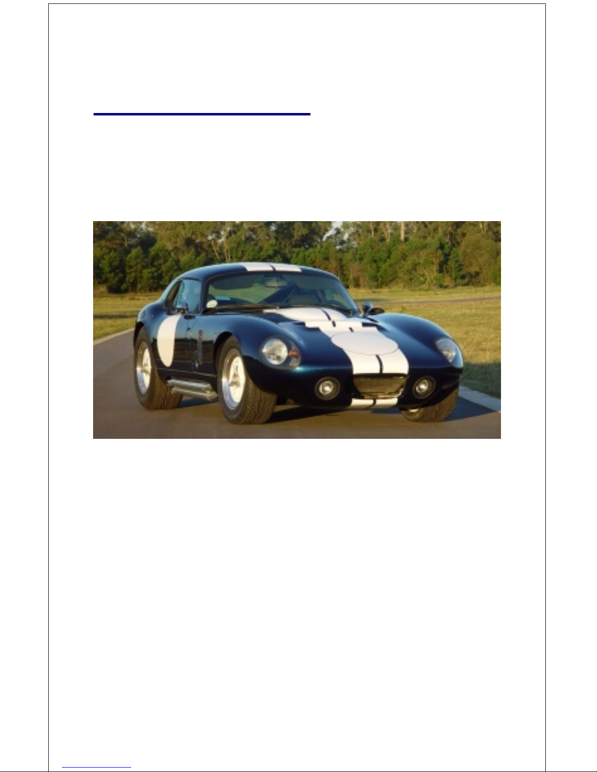
Figure 1 Superformance Coupe.....................................................................1
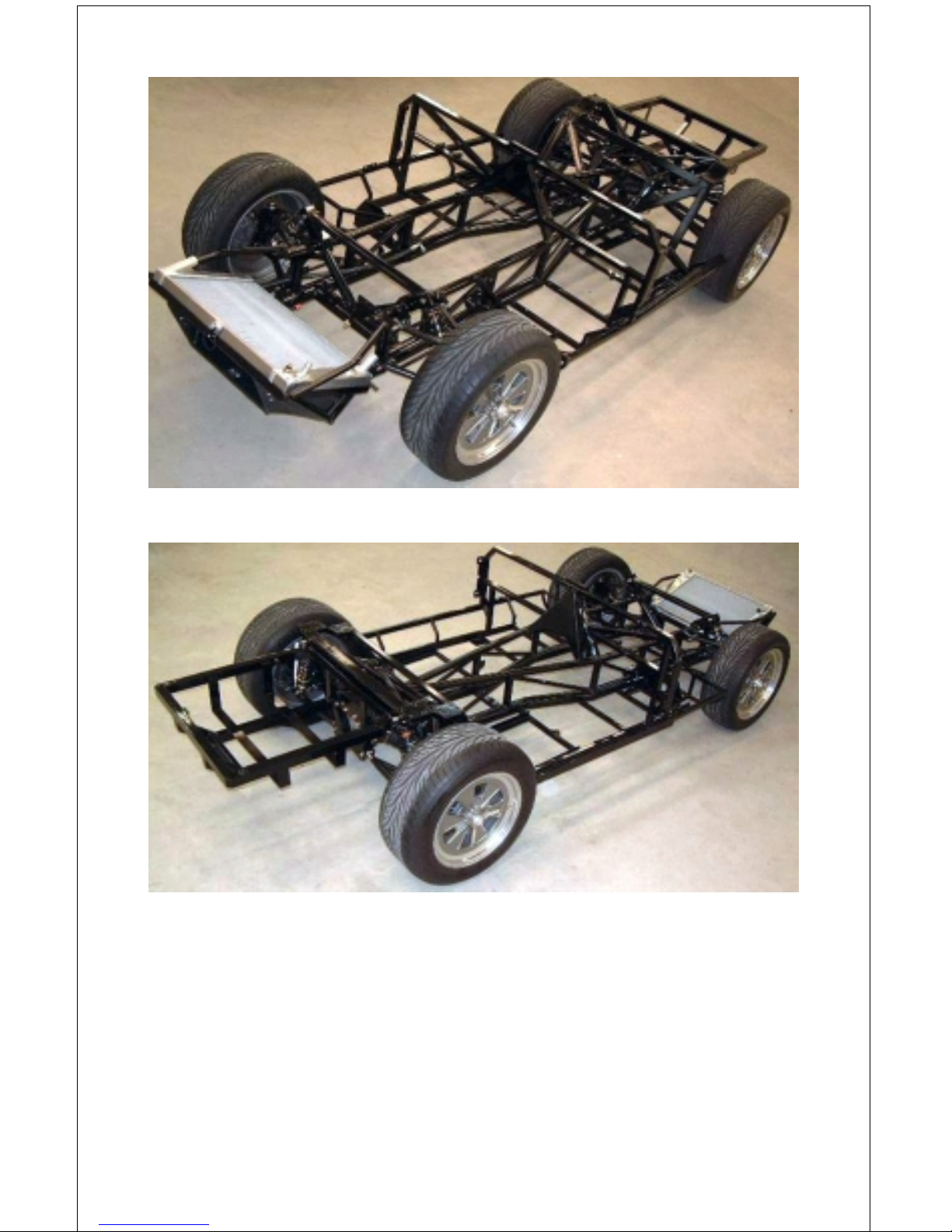
Figure 2 Superformance Chassis, Front View...............................................3
Figure 3 Superformance Chassis, Rear View................................................3
Figure 4 Speedometer and tachometer..........................................................7
Figure 5 Gauges ............................................................................................8
Figure 6 Fuel pressure gauge ......................................................................10
Figure 7 Controls and switches...................................................................11
Figure 8 Controls and switches...................................................................12
Figure 9 Interior light switch.......................................................................15
Figure 10 Adjustable air vents ......................................................................16
Figure 11 Door release button driver’s side..................................................17
Figure 12 Door release button passenger’s side and DC power....................17
Figure 13 Manual operation door lever.........................................................17
Figure 14 Remote immobilizer .....................................................................18
Figure 15 Hand brake and gear lever............................................................18
Figure 16 Gear lever knob.............................................................................19
Figure 17 Warning lights and buzzers...........................................................19
Figure 18 Fuel inertia switch location...........................................................20
Figure 19 Fuel inertia switch.........................................................................20
Figure 20 Glove compartment.......................................................................21
Figure 21 Cup holders...................................................................................21
Figure 22 General stowage compartments....................................................22
Figure 23 Inside the stowage compartment...................................................22
Figure 24 Washer bottle compartment..........................................................23
Figure 25 Washer bottle reservoir.................................................................23
Figure 26 Scissor jack compartment.............................................................24
Figure 27 Scissor jack, handle and hammer..................................................24
Figure 28 Keys..............................................................................................27
Figure 29 Hood latch.....................................................................................28
Figure 30 Trunk lock.....................................................................................29
Figure 31 Le Mans vintage competition style gas filler................................30
Figure 32 Locking type gas cap ....................................................................30
Figure 33 Seat adjust, seat belt and lumbar ...................................................31
Figure 34 Battery location and main power cut off switch ...........................33
Figure 35 Removing left side wheels............................................................34
Figure 36 Removing right side wheels..........................................................34
Figure 37 Hood raised, jack point for LH front suspension..........................36
Figure 38 Scissor jack locating slid into p osition under left hand
lower control arm..........................................................................36
Figure 39 Scissor jack locating point for right hand front suspension ..........37
Figure 40 Hood raised, jack slid into position under right hand
lower control arm..........................................................................37
Figure 41 Scissor jack locating point for left hand rear suspension..............38
Figure 42 Scissor jack locating point for right hand rear suspension............38

Page viii
Figure 43 Drive pin holes in rim center ........................................................38
Figure 44 Drive pins on hub center...............................................................39
Figure 45 Towing eye and mounting bolt.....................................................40
Figure 46 Front tow hook mount points........................................................41
Figure 47 Rear tow hooks mount points .......................................................41
Figure 48 Front wheel toe vs. wheel movement............................................44
Figure 49 Setting rear static toe.....................................................................46
Figure 50 Rear wheel toe vs. wheel travel ....................................................47
Figure 51 Rear wheel toe ..............................................................................49
Figure 52 Fluid reservoirs.............................................................................51
Figure 53 Power steering fluid reservoir.......................................................53
Figure 54 Engine oil dip stick. A/C ports......................................................54
Figure 55 Remove fastening screw...............................................................59
Figure 56 Remove plastic cover....................................................................59
Figure 57 Indicator cover..............................................................................59
Figure 58 Indicator bulb................................................................................59
Figure 59 Plastic access cover.......................................................................60
Figure 60 Loosen screw through hole...........................................................60
Figure 61 Remove surround..........................................................................60
Figure 62 Remove lens fastening screw........................................................60
Figure 63 Unplug the light............................................................................61
Figure 64 Compress spring clip and remove bulb.........................................61
Figure 65 Spot light cover.............................................................................61
Figure 66 Plastic spot light shroud................................................................61
Figure 67 Remove fastening ring..................................................................62
Figure 68 Unplug white wire ........................................................................62
Figure 69 Loosen screw................................................................................62
Figure 70 Replace bulb and wire...................................................................62
Figure 71 Remove chrome rim......................................................................63
Figure 72 Remove indicator lens ..................................................................63
Figure 73 Removal of number plate lamp cover...........................................64
Figure 74 Hinged tray housing fuses.............................................................65
Figure 75 Cluster 1 Relays and fuses under the dash....................................66
Figure 76 Radiator fan plug left hand ...........................................................67
Figure 77 Radiator fan plug right hand .........................................................67
Figure 78 Radiator cowl and fans .................................................................68
Figure 79 Cowl fastener O-ring ....................................................................68
Figure 80 Plastic cover over fuses in engine bay ..........................................68
Figure 81 Cluster 2 Relays and fuses in the engine bay................................69

Page ix
ADDITIONAL INFORMATION TO BE PROVIDED
The Coupe Owner’s Manual provides places to write information
that is specific to your car.
To be provided by owner and/or Superformance dealer
Vehicle and owner information........................................................i
Keys............................................................................................... 27
To be provided by engine builder/installer
Minimum, maximum, break-in engine speeds................................ 7
Oil temperature................................................................................ 8
Water temperature........................................................................... 8
Oil pressure ..................................................................................... 9
Fuel pressure ................................................................................. 10
Engine oil ......................................................................................50
Transmission fluid.........................................................................50
Differential fluid............................................................................ 51
Fuel octane requirement................................................................52
V-belt size ..................................................................................... 55
Spark plugs.................................................................................... 55

Page x
Page 1
SPECIFICATIONS
General Specifications
Congratulations on your purchase of a Superformance® component
vehicle! With proper care and maintenance your Superformance
should supply you with years of pleasure and enjoyment. Prior to
operation please familiarize yourself with the information
contained in this book.
[Figure 1 - Superformance Coupe]
The vehicle is supplied by Superformance as a complete and fully
equipped rolling chassis less engine and transmission. Please check
with the installer of your engine and transmission for break-in
details and specifications for your engine and transmission and
record the information in the space provided in this manual.
Superformance makes running engineering changes as
requirements are identified. The specifications herein are typical
for cars in current production at the time of compilation of this
manual. Specifications for individual cars may vary.
Chassis
Jig-Welded tubular steel space frame.

Page 2
Body
Composite construction with superior aerodynamics. Hand laid
fiberglass panels with Vinyl ester resin. All mounting points plated
prior to lamination. Forward hinging doors and hood double
skinned for added re-enforcement.
Front suspension
Fully independent suspension using unequal length A-arm design,
adjustable coil springs over telescopic shock absorbers and anti roll
bar.
Rear suspension
Fully independent suspension using unequal length A-arm design,
with a toe control link, adjustable coil springs over telescopic
shock absorbers and anti roll bar.
Steering
Power assisted Rack and pinion with 2.5 turns lock to lock giving a
turning circle of 42ft. Ratio 16.1:1.
Pedal box
Floor mounted pedals. Pedals integrated into the space frame
chassis. Pedal pads adjustable. Accelerator pedal height can be
adjusted.
Brakes
Vacuum boosted system. PBR 2 pot floating calipers front, 1 pot
floating calipers rear with vented discs:
FRONT – 12.8” x 1.25”
REAR – 12” x 1”
Cooling
Latest technology high performance aluminum core radiator with
built-in oil cooler. Two thermostatically-controlled electric fans.
Page 3
[Figure 2 – Superformance Chassis, Front View]
[Figure 3 – Superformance Chassis, Rear View]

Page 4
Exhaust system
Fabricated headers bolt onto original side pipe design but with
gases continuing back into rear mounted exhaust pipes protruding
through lower rear of the body.
Interior
The cockpit is trimmed in top quality automotive carpeting, leather
and Alcantara materials. The cockpit also houses a 4-point roll bar,
a black padded roof liner, 3 point retractable seat belts (See seat
belt operation on page 32), an original style 14” Motolita steering
wheel and an interior light on the roof lining behind the
windshield.
Mechanical Compone nts
Engine
The Superformance Coupe has been designed to use:
• A Ford 351 Windsor block or aftermarket equivalent with
standard 9.5 inch deck height
• Cylinder heads with exhaust ports in the stock location and
with shape and dimensions consistent with AFR 185 cylinder
heads
• A single four barrel with a dual-plane intake manifold
These specifications are dictated respectively by:
• Space within the engine compartment
• Exhaust header design and frame clearance
• Hood clearance
Within these constraints, the owner has a wide choice of 351W
based engines from 351 to 427 cubic inches with up to 600
horsepower or more from a number of engine builders.

Page 5
Transmission
The Superformance Coupe is designed to use the Tremec T-56
6-speed manual gearbox from TTC (Transmission Technologies
Corporation).
The following speeds are the maximum calculated speeds based on
recommended tire size, T-56 gear ratios, 3.46 final drive, and a
6000 rpm redline. The actual speeds attainable in the higher gears
depend on the engine selected.
Gear Ratio mph/1000 rpm Max speed in gears
1 2.97 8.2 49 mph (6000 rpm)
2 2.07 12.0 71 mph (6000 rpm)
3 1.43 17.1 102 mph (6000 rpm)
4 1.00 24.4 146 mph (6000 rpm)
5 0.80 30.5 183 mph (6000 rpm)
6 0.62 39.4 236 mph (6000 rpm)
CAUTION: Because the Coupe has low drag, speeds in excess of
200 mph may be possible with engines of 500 or more horsepower.
Speeds higher than legal highway speeds should only be attempted
by experienced drivers with proper safety equipment on closed
courses designed for such speeds.
NOTE: REVERSE GEAR LOCK OUT SWITCH
The clutch pedal AND the brake pedal MUST be depressed before
reverse gear can be engaged. The depressing of the brake pedal
activates an electronic mechanism on the gearbox which allows
reverse gear to be engaged.
For your safety, the Tremec employs a neutral safety switch that
will only allow the engine to be cranked and started while neutral
is selected.
Differential
BTR Hydratrac (3.46:1 ratio) limited slip differential designed for
independent rear suspension is fitted as standard equipment.

Page 6
Wheels and Tires
Front Wheels.....................Aluminum 18" x 8” peg drive knock off
Rear Wheels ....................Aluminum 18” x 10” peg drive knock off
Design Tire Sizes
Front..................................................................................255/45-18
Rear ...................................................................................285/50-18
Optional Tire Sizes
Front..................................................................................255/40-18
Rear ...................................................................................295/45-18
NOTE: Be sure to obtain a speed rating consistent with the speeds
you expect to drive. A minimum of a Z rating is recommended.
Dimensions
Curb weight..........................................................................3066 lbs
Weight distribution front/rear............................................ 49%/51%
Wheelbase:...................................................................................93"
Length: .......................................................................................175"
Height...........................................................................................49"
Width.........................................................................................73.5"
Track front:................................................................................56.5"
Track rear:.................................................................................58.5"
Ground clearance: .....................................................................6.25"
Fuel tank:..................................................... 21 gallon stainless steel
Curb weight and weight distribution are typical for a 351W engine
with an iron block and aluminum heads and a T-56 transmission.
Page 7
OPERATION
Instrumentation
Full instrumentation, gauges and warning lights are provided with
the Superformance rolling chassis. The gauges and warning lights
must be correctly hooked up during the engine and transmission
installation to function properly. The gauge and warning light
readings are dependant on engine and transmission specifications
and installation procedures. The following information is therefore
provided as general guidelines only. The actual gauge readings
should be determined by the owner and written in the spaces
provided.
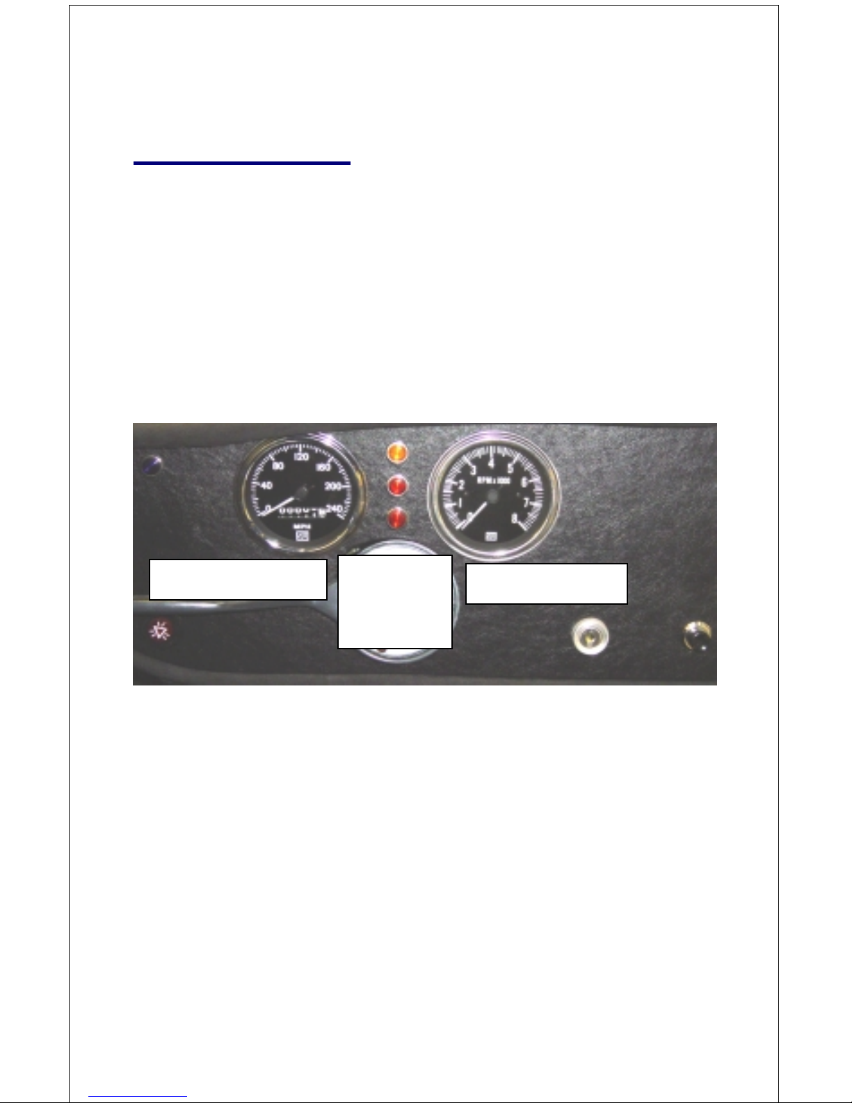
[Figure 4 - Speedometer and tachometer]
Speedometer
The speedometer (1) indicates the speed of the car in miles per
hour.
Tachometer
The tachometer (2) indicates the engine speed in revolutions per
minute. Your engine provider should specify the minimum and
maximum engine speeds for the engine you have selected.
Minimum engine speed: _____ rpm
Maximum engine speed, break in: _____ rpm for _____ miles
Maximum engine speed: _____ rpm
Steering
wheel
position
1 Speedometer
2 Tachometer
Page 8
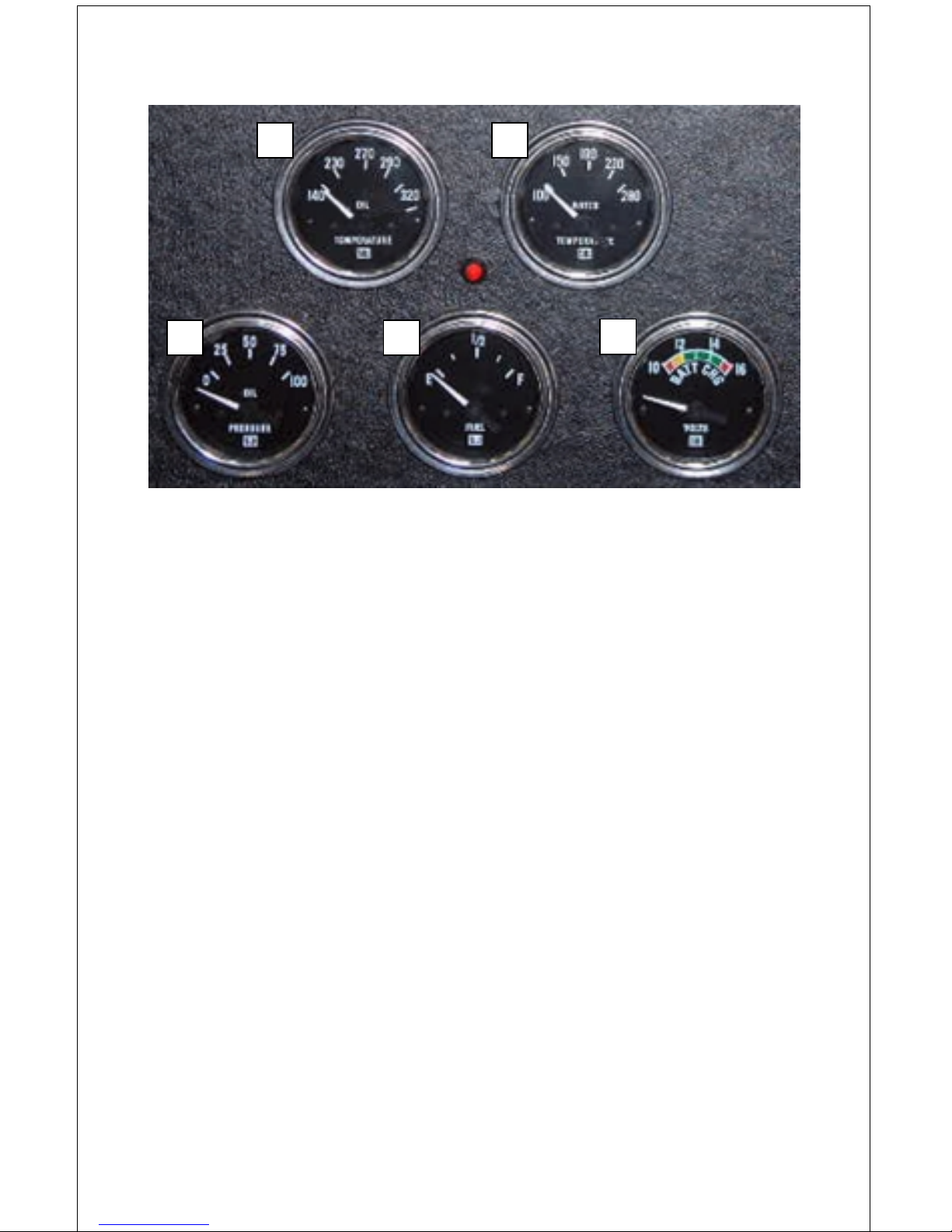
[Figure 5 - Gauges]
Oil Temperature Gauge
The oil temperature gauge (3) indicates the engine oil temperature
in degrees Fahrenheit. The oil temperature during normal driving
should be approximately the same as the water temperature. It will
be somewhat lower until the engine fully warms up and during
cold weather. It will be higher during high speed driving. If the
oil temperature exceeds the maximum during high speed driving,
additional oil cooling capacity may be required.
Normal oil temperature: __________ degrees Fahrenheit
Maximum oil temperature: __________ degrees Fahrenheit
Water Temperature Gauge
The water temperature gauge (4) indicates the engine water
temperature in degrees Fahrenheit. The normal operating
temperature depends on the thermostat installed. Your engine
provider should specify the normal water temperature.
Normal water temperature: __________ degrees Fahrenheit
If the water temperature exceeds 230 degrees Fahrenheit, the
engine should be shut down and allowed to cool before
3
5 6
7
4
IMMOBILIZER
LED

Page 9
proceeding. Water temperatures above 210 degrees Fahrenheit
during normal driving indicate a problem that needs to be
corrected.
For those more familiar with Centigrade:
Fahrenheit Centigrade
100.................. 38
140.................. 60
150.................. 66
190.................. 88
230................. 110
270................. 132
280................. 138
290................. 143
320................. 160
Oil Pressure Gauge
The oil pressure gauge (5) indicates the oil pressure in pounds per
square inch (PSI). Your engine provider should specify the
minimum and maximum oil pressure for the engine you have
selected. If the oil pressure drops below the minimum, it may
indicate a serious problem. The engine should be shut down
immediately until the problem is identified and corrected.
Minimum oil pressure: __________ PSI at __________ rpm
Maximum oil pressure: __________ PSI at __________ rpm
Fuel Gauge
The fuel gauge (6) indicates the fuel level in the fuel tank.
NOTE: This is an approximate indication. You should set your
own limits
Volt Meter
The volt meter (7) indicates voltage reading of the alternator and
the battery.
Page 10
ALTERNATOR: When the engine is running the Volt meter
will show the charging voltage from the alternator to the
Battery.
BATTERY: When the engine is off and ignition turned to
position 1 the volt meter will show the condition of the
battery power in volts.
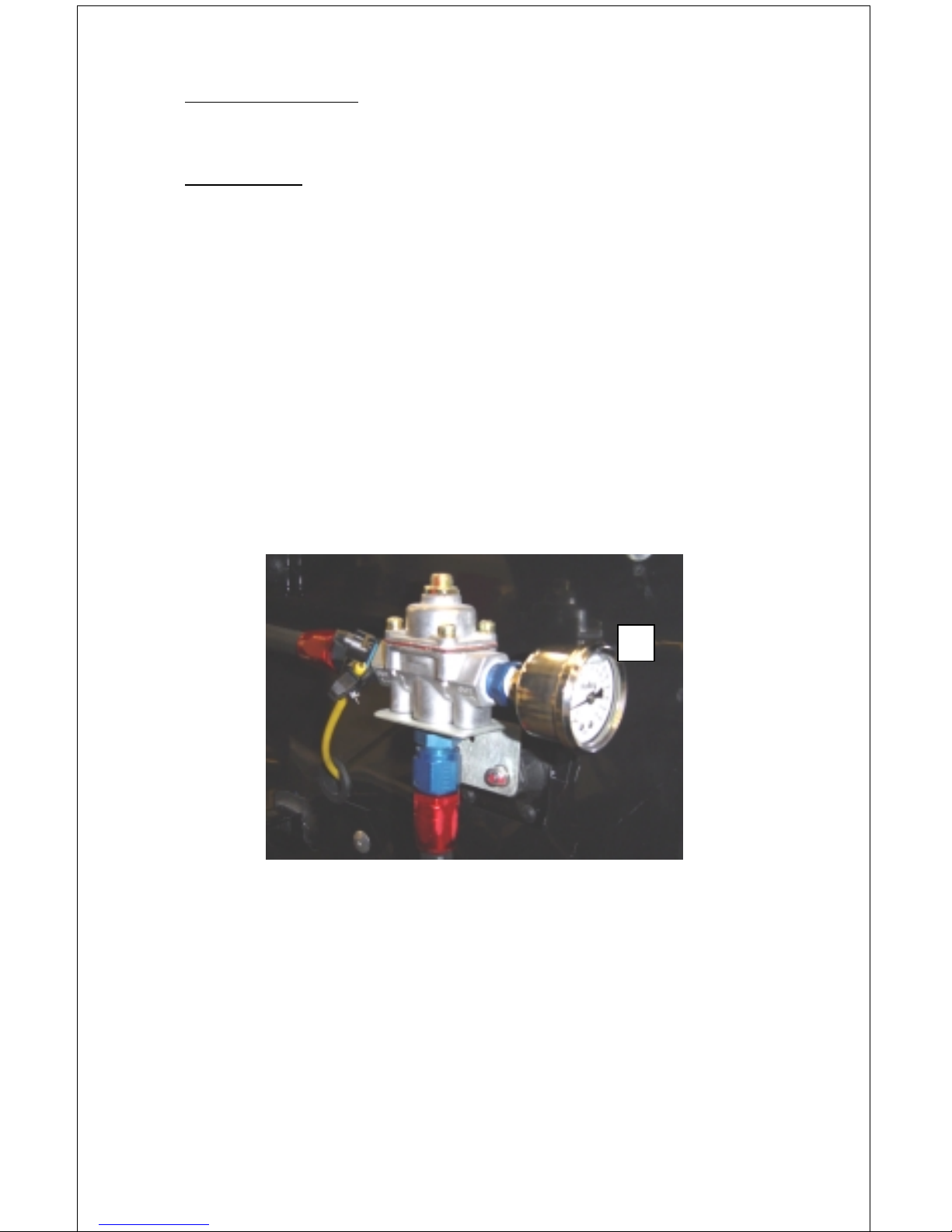
Fuel pressure gauge
The fuel pressure gauge (8) is attached to the fuel pressure
regulator, which is mounted to the firewall in the engine bay (See
Figure 6 below). The gauge measures the pressure of the fuel
supply at the regulator, between the fuel pump to the carburetor.
The pressure is measured in PSI. The fuel pressure can be adjusted
at the regulator. The required fuel pressure setting may vary
depending on the carburetor fitted. See your engine builder for the
specific set up requirements for your carburetor.
[Figure 6 - Fuel pressure gauge]
Fuel pressure: __________ PSI at __________ rpm
8
Page 11
Controls and Switches
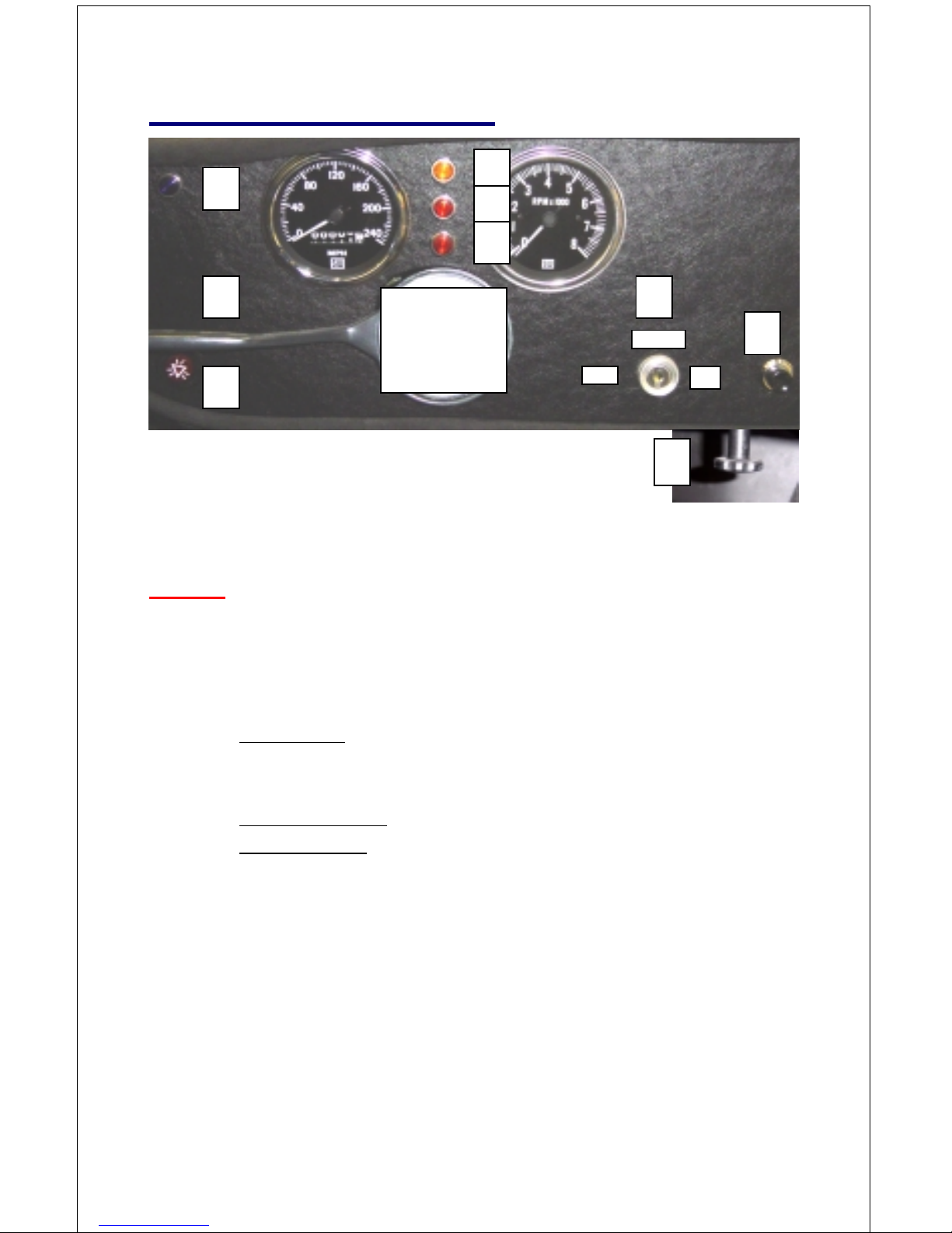
[Figure 7 - Controls and switches]
NOTE: For digital watch owners, clockwise is top to the right,
counterclockwise is top to the left.
Ignition Switch
The ignition switch (9) has 3 positions:
I Accessory – key turned counterclockwise (to left)
Only the radio and the DC accessory power ports have
electrical feed with the ignition switch in this position.
II Ignition “OFF” – Key in middle position.
III Ignition “ON” – Key turned clockwise (to right). This
switch position activates all functions which require
electrical feed. (See Start Procedure on page 25)
Turn Signal Indicator / Hi Beam Stalk
The turn signal stalk / lever (10) is mounted on the steering
column, typically on the left hand side. Move the stalk in the
direction you want to turn to activate the turn signal. When the turn
signals are on, the turn signal indicator light (31) will flash.
Steering
wheel
position
13
910
11
III
II
I
34
31
32
33
12
Page 12
When the headlights are turned on, click the switch on the back of
the tip of the turn signal stalk to switch between high beams and
low beams. When the high beams are on, the hi-beam pilot light
(34) will be on. When the headlights are not on, clicking the switch
on the turn signal stalk flashes the high beams.
Horn
The horn button (11) is located on the dashboard. Pushing the
button sounds the horns.
Dash Dimmer Switch
The dashboard dimmer switch (12) is situated on the under side of
the dash, below the horn button, and is used to control the intensity
of the dashboard lights. Turn the dimmer switch counterclockwise
to dim the dashboard lights and clockwise to brighten them.
Hazard Light Switch
This switch (13) activates the hazard / emergency lights. Depress
the switch and the indicator light (31) will flash. The switch will
also flash bright red. Press the switch again to stop the indicators
and switch from flashing.
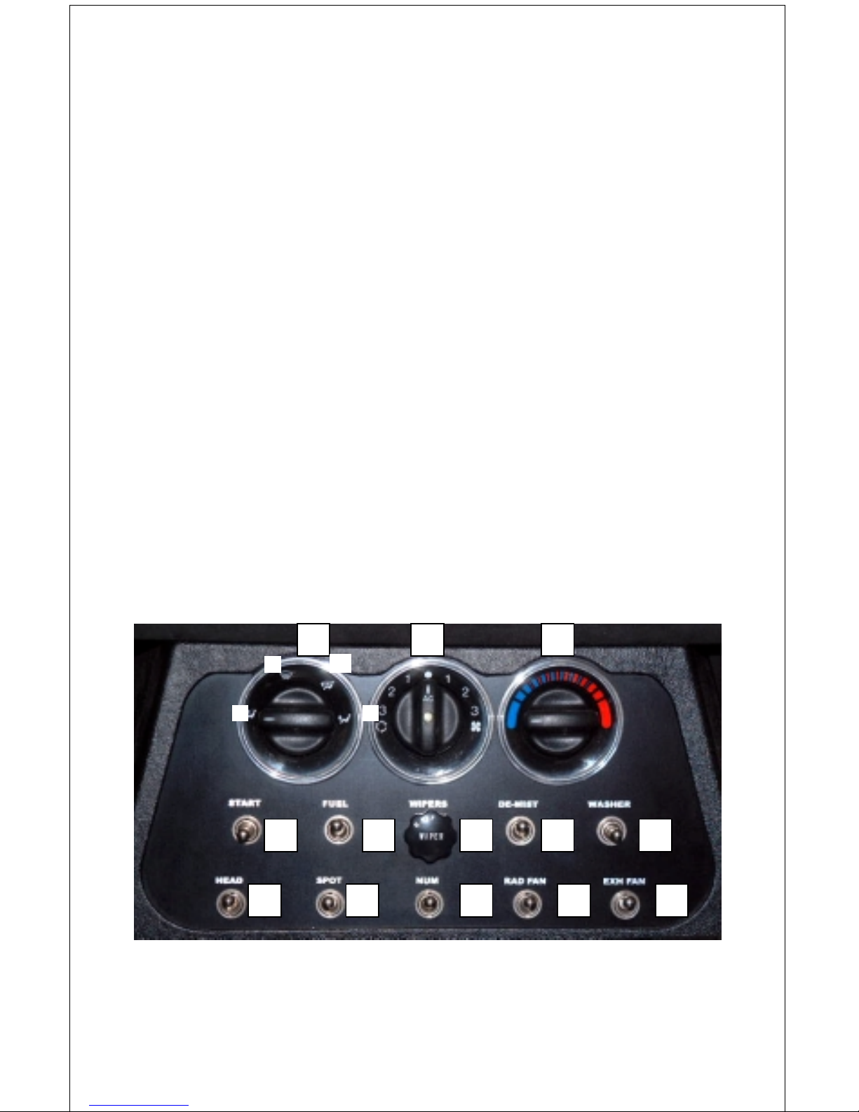
[Figure 8 - Controls and switches]
14 15
17 18 19 20 21
22 23 24 26
16
25
I
II
III
IV

Page 13
Climate Control Air Flow D irectional
This control (14) has 4 settings.
I Air flow to head only.
II Air flow is 70% head and 30% feet
III Air flow 30% head and 70% feet
IV Air flow to feet only
From position II to position III, the airflow varies continuously
from 70/30 to 30/70 head to feet. In the middle, it is 50/50, for
example.
This control does not operate the de-mister. See Figure 17 – item
# 20 on page 19 for information on de-mister operation.
Air Flow Source
The fan control (15) has three fans speeds. Turn the control
counterclockwise (to left) for re-circulated air. Turn the control
clockwise for fresh air.
Air Conditioning
Push in the fan control knob (15) to turn the air conditioning on
and off. The small green light in the center of the knob will be on
when the air conditioning is on.
Temperature Control
Turn the temperature control (16) counterclockwise (to the left) for
cold air and clockwise (to the right) for warm air.
Start Switch
This switch (17) can be toggled up OR down for engine starting.
(See Start Procedure on page 25)
Fuel Pump Toggle Switch
The fuel pump switch (18) controls the electric fuel pump. Up is
off and down is on. Be sure to turn the fuel pump on before
starting the car. Although the electric fuel pump shuts off when

Page 14
the ignition is turned off, it is a good idea to turn off the electric
fuel pump switch as well. Remember to turn it back on when you
start the car. If the pump is switched off (up), the car may start, but
will shut down in a short while when the fuel supply in the
carburetor bowl is used up.
Windshield Wiper Rotary S witch
The two speed windshield wiper switch (19) has 3 positions:
P Park (off)
N Normal (low) speed wiper
H High speed wiper
From park, rotate the switch clockwise (to right) one position for
low speed wiper operation and two positions for high speed wiper
operation. Rotate the switch counterclockwise to slow or turn off
the wipers.
De-Mist Toggle Switch
Toggle the switch (20) downward to activate the wind shield demister.
Windshield Washer Toggle Switch
The windshield washer can be activated by toggling switch (21)
upwards or downwards.
Headlight Toggle Switch
Toggle the headlight switch (22) to the full up position to turn off
the lights. Toggle the switch down one position to turn on the
running lights and down two positions to turn on the headlights.
The dashboard lights come on automatically when the running
lights or headlights are switched on.
Spot Light Toggle Switch
Toggle the switch (23) downward to switch on the spot lights. The
spot light only come on when the headlights are on.
Page 15
Number Toggle Switch
(Optional) All coupes have plugs in the door loom for the
connection of a light on the door to illuminate the racing number.
Toggle the switch (24) downward to activate this light.
Radiator Fan Override Toggle S witch
The radiator fans are switched on automatically when the engine
temperature exceeds 203 to 207 degrees Fahrenheit and when the
air conditioning is on. The radiator fan override toggle switch (25)
enables you to turn the radiator fans on manually when the water
temperature gauge indicates that the engine temperature is
approaching 203 degrees Fahrenheit, typically in slow traffic. Up
is off and down is on.
Engine Compartment / Exhaust Fan Toggle Switch
Fans have been fitted in the engine bay below the exhaust to
remove excess heat in the engine bay. This is especially useful
when driving slowly or through traffic, when the temperature rises
due to lack of air flow. Toggle the switch (26) downward to
activate these fans.
NOTE: The Radiator OR engine compartment / exhaust fans will
sometimes come on automatically after the engine has stopped.
This is normal and they will shut off automatically when the
engine cools.
Interior Light Switch
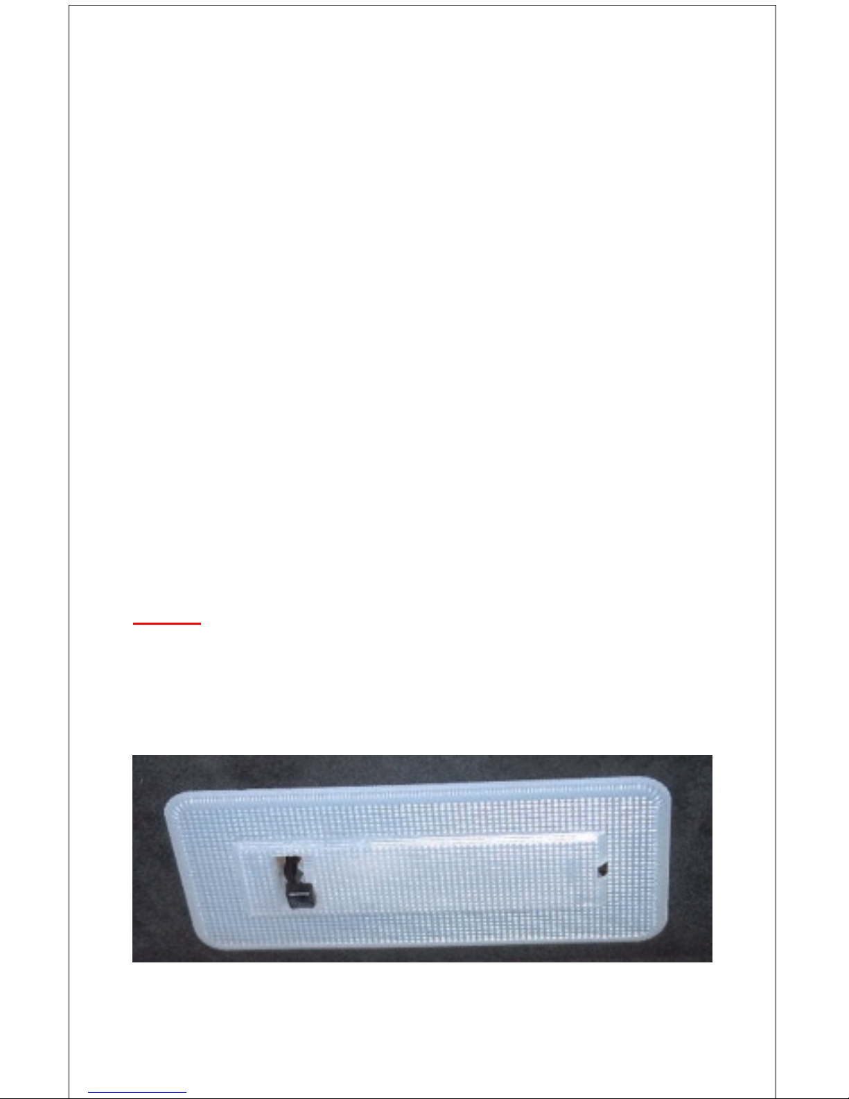
[Figure 9 - Interior light switch]
1
2
3
Page 16
The interior light switch has 3 positions:
1) Door activated – “ON” when door open
2) Manual light “OFF” position
3) Manual light “ON” position
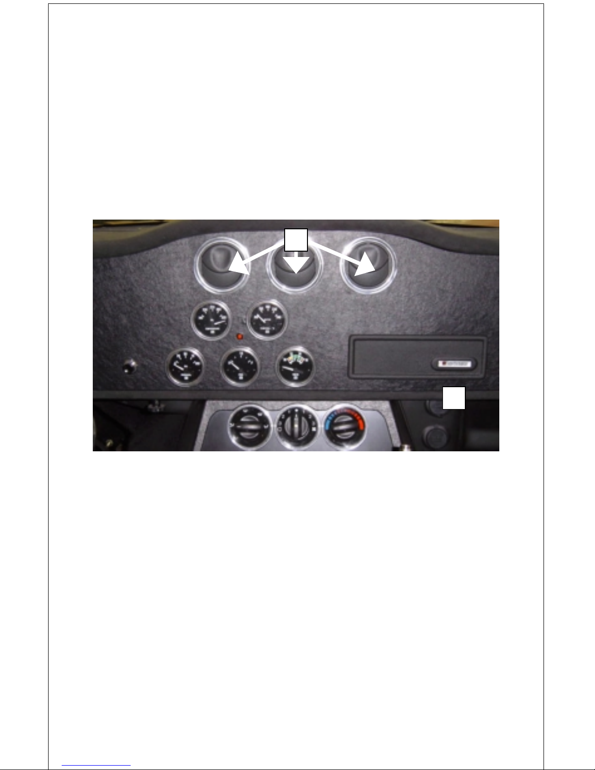
Adjustable Air Vents
These dash mounted vents (27) are fully adjustable in all directions
and are situated above the center gauges and air conditioner
controls
[Figure 10 - Adjustable air vents]
Removable Co ver for Radio Fitment
Remove the plastic cover (28) to reveal the radio fitment aperture
Side Windows
The doors house retractable toughened glass side windows,
manually operated.
Door Release Buttons
The door locks can be activated by depressing buttons on the sides
of the center console switch panel (29). There is a button on the
left side of the switch panel for driver’s side and on the right side
for the passenger side door release.
28
27
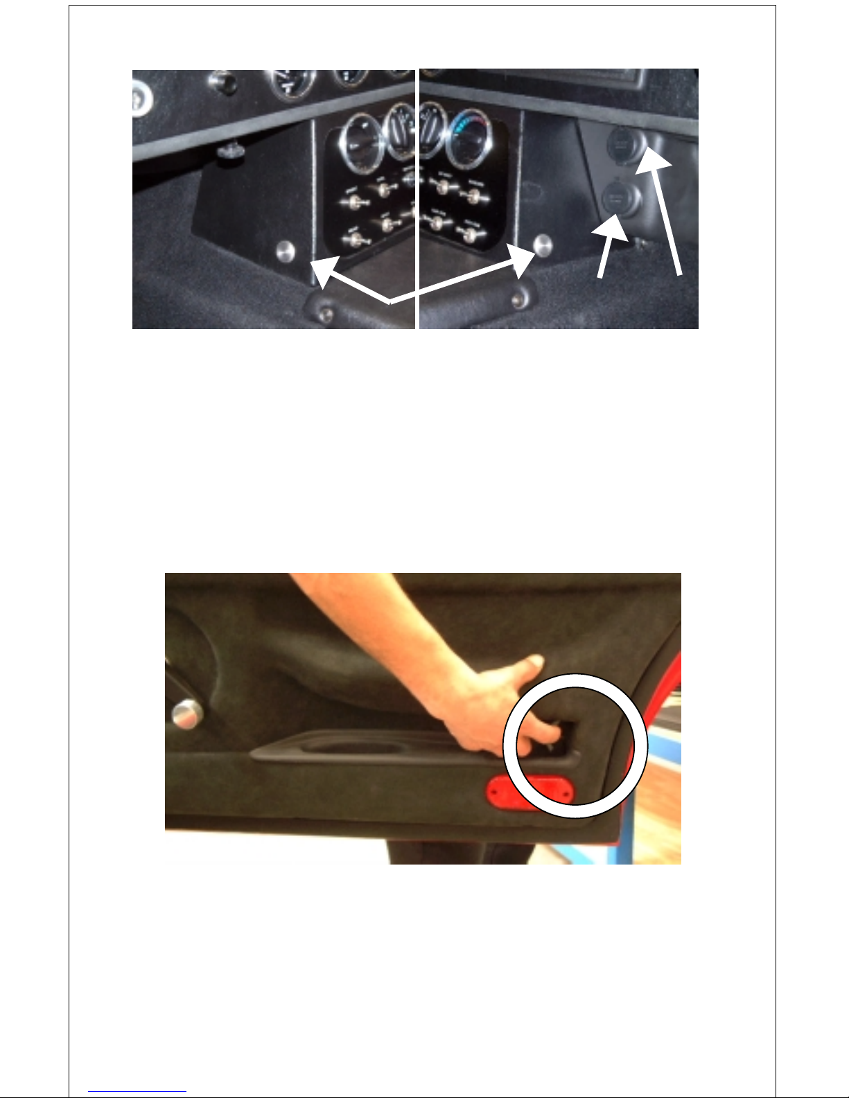
Page 17
[Figure 11 - Door release
button driver’s side]
[Figure 12 - Door release
button passenger’s side and
DC power accessory ports]
Manual Door Operation
The doors can also be manually opened from inside the cockpit
using the door levers housed in recesses in the bottom rear of the
door panel.
[Figure 13 - Manual operation door lever]
Door release buttons
DC power
accessory ports

Page 18
Remote Immobilizer
A remote immobilizer is supplied with the vehicle. The remote
immobilizer is used to unlock the doors (two clicks) and to unlock
the ignition (one click). See page 26 for doors and page 25 for
starting.
[Figure 14 - Remote immobilizer]
DC Power Accessory Ports
These can be used to supply power to 12 volt plug-in automotive
accessories (See Figure 12 on page 17)
Hand Brake
To apply the hand brake, pull the handle rearwards while
depressing the button at the end of the lever. Release the button at
the end of the lever’s travel. To release, press the button and move
the lever forward fully.
[Figure 15 - Hand brake and gear lever]
 Loading...