

Page 1

2010
INSTRUCTION MANUALINSTRUCTION MANUAL
SPECIFICATIONS
WING SPAN: 1800 mm(70.86 in)
2 2
WING AREA: 33.5 dm (519 in )
LENGTH: 928 mm(36.5 in)
WEIGHT: 1100g(38.8 oz)
RADIO: 4 Ch
Warning
An RC aircraft is not a toy! If misused, it can cause serious bodily
harm and damage to property. Fly only in open areas, following all
instructions included with your radio.
Before beginning the assembly, remove each part from its bag for
inspection. Closely inspect the fuselage, wing panels, rudder and
stabilizer for damage. If you find any damaged or missing parts,
contact the place of purchase.
Page 2
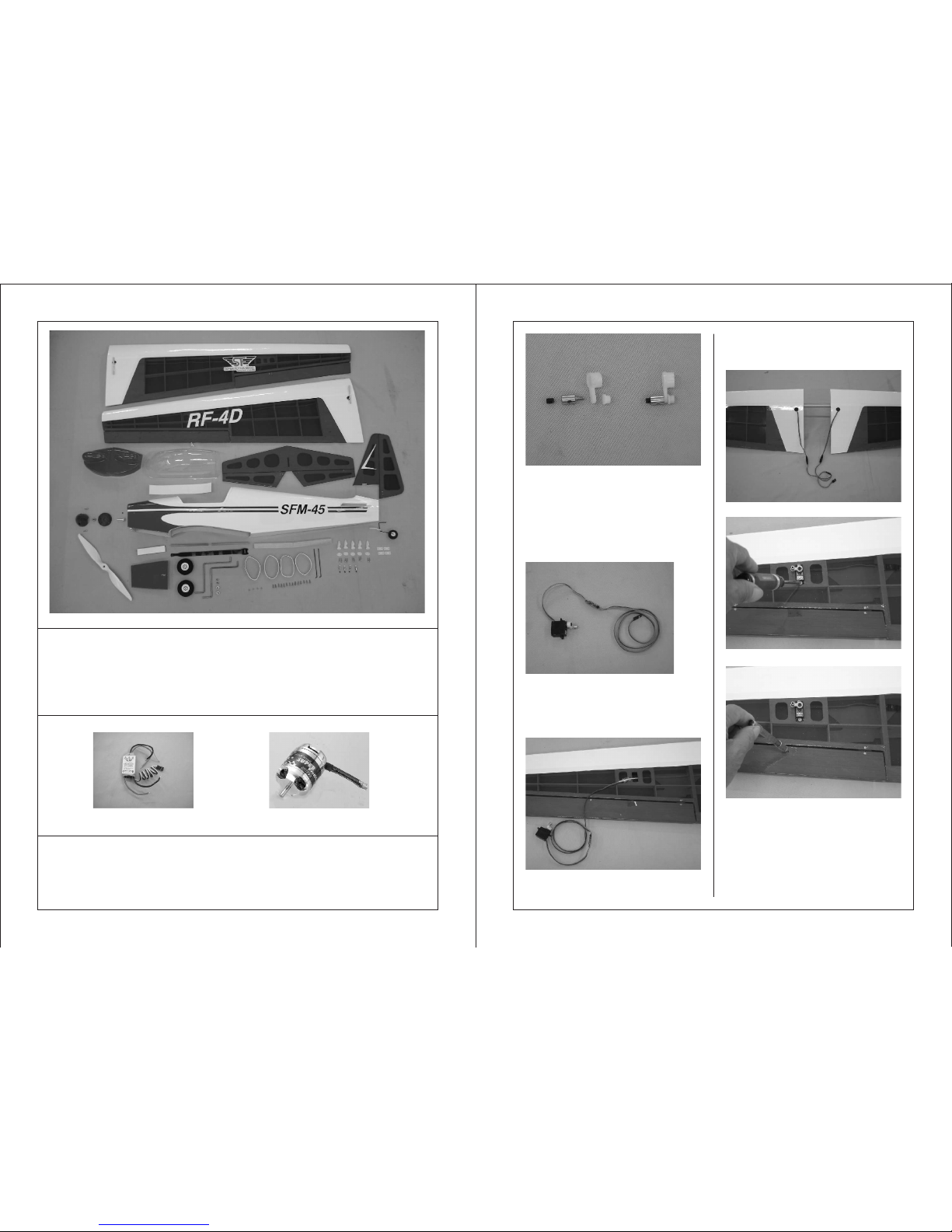
Recommended radio and electronic equipment (Not included in kit):
4 Channels or up radio
9g servo x 2 pieces
17g servo x 2 pieces
Receiver
Y-Harness
30A speed control (#2421)
1 2
Contents of Kit / Parts Layout
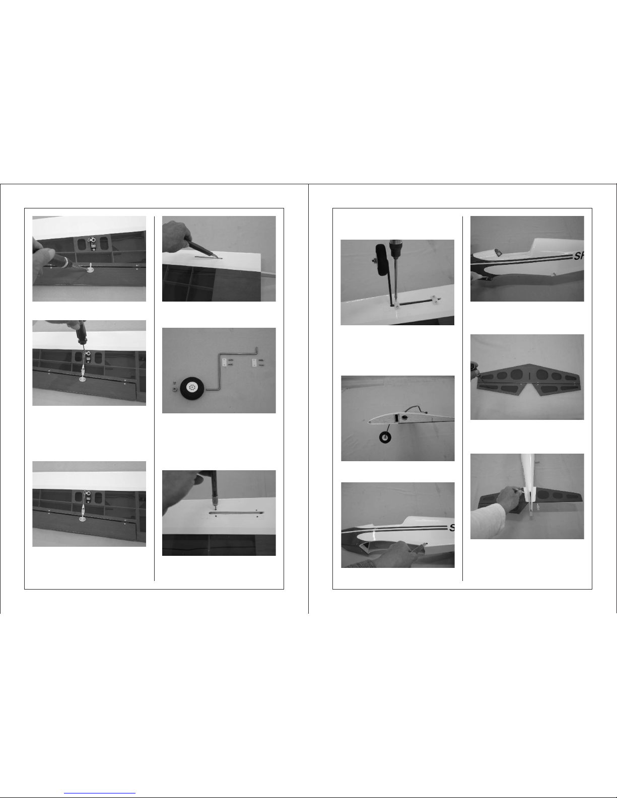
Place the M2 plastic nut, pushrod
connector and M3 hex screw on the
working table. Drill 2mm hole on the
servo arm. Slide the pushrod
connector into the hole. Secure the
connector using a M2 plastic nut.
Do not secure too tight. Make sure the
servo arm can move freely.
Connect the female plug of the 600mm
extension with the male plug of servo.
Use transparent tape to circle the
connecting place for preventing
loosening.
Optional accessories
Required Tools and Adhesives
1.5mm Hex wrench
Hobby Knife
Ruler
Pliers
Small Phillips Screwdriver
2mm drill
curved scissors
Epoxy 5-minute
Pen
CA glue
solder iron and solder
Li-Po battery 2000mAh or up
3-Cell 11.1V battery
1000KV 12-Pole brushless motor
600mm extension x 2 pieces
Optional accessories
#2421 30A
brushless Speed Control
#2200-F18-1000-B 1000KV
12-pole brushless motor
Tight cotton line on the male plug of
the extension. Route the line through
Connect the extensions with Y-harness.
Secure the servo on the servo try.
Take one piece of control horn out of
the hardware bag. Place the control
horn on the aileron and make sure its
position is straight to the servo. Use
pen to mark the holes on the aileron.
Use 2mm drill to drill the holes.
the pre-drilled holes on the rib. Cut off
the cotton line when the extension is
out of the hole.
Page 3
3
4
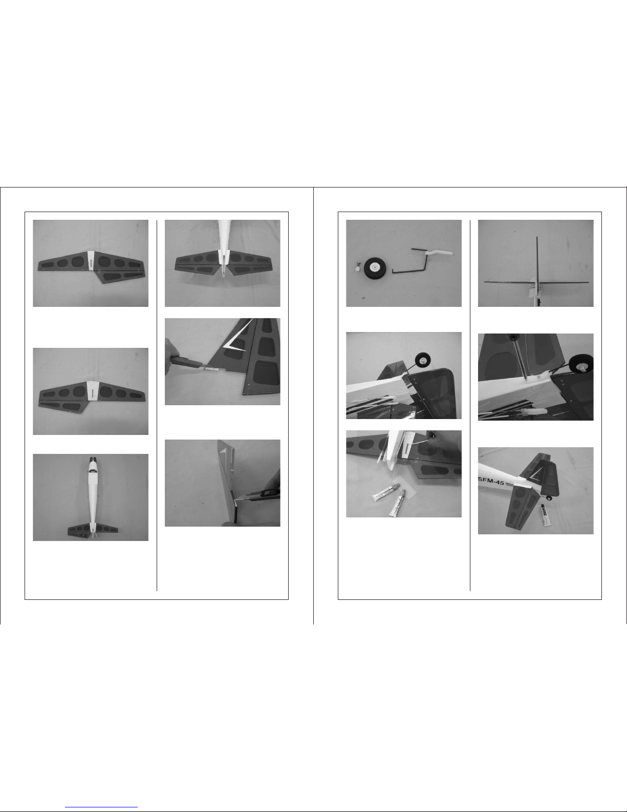
Use 2 pieces of 2x13mm screws to
secure the control horn in place.
Use hobby knife to remove the
covering on the pre-serving slot for the
landing gear.
Assemble the landing gear with wheel
and collar. Secure the collar with 3x6
screws. Insert the landing gear into
the gear slot. Secure the landing gear
in place using the plates and 3x10
tapping screws.
Insert the dowel. Make sure the dowel
on both sides are the same length and
apply some instant glue to secure the
dowel.
Thread the clevis on one end of the
rod and connect the clevis with control
horn. Slide in one piece of silicone
tube. Slide the other end of rod into
the servo arm. Center the aileron and
secure the rod using 3 x 4mm hex
screw.
Move the silicone tube to the clevis for
preventing the clevis loosening from
control horn during flying.
Take out the following accessories for
assembling the landing gear:
3 x 10mm tapping screw 8 pieces
gear plate 4 pieces
collar 2 pieces
3x 6 screw 2 pieces
wheels 2 pieces
Insert the landing gear into the gear
slot. Place the gear plate over the slot.
Using pen to mark the position for
Please note the landing gear will be
forward 10 degree after assembly.
Use hobby knife to cut off the covering
on the dowel hole.
Place the horizontal on the working
table. Use Philip screw to loose the
screws on the hinges for removing
one piece of elevator temporary.
Slide the horizontal into the fuselage.
Center the horizontal to the fuselage
and carefully mark the position with a
pen at the junction where the
horizontal meets the fuselage.
securing the plate. Remove the plate
and gear. Use 2mm drill to open the
holes.
Page 4
65
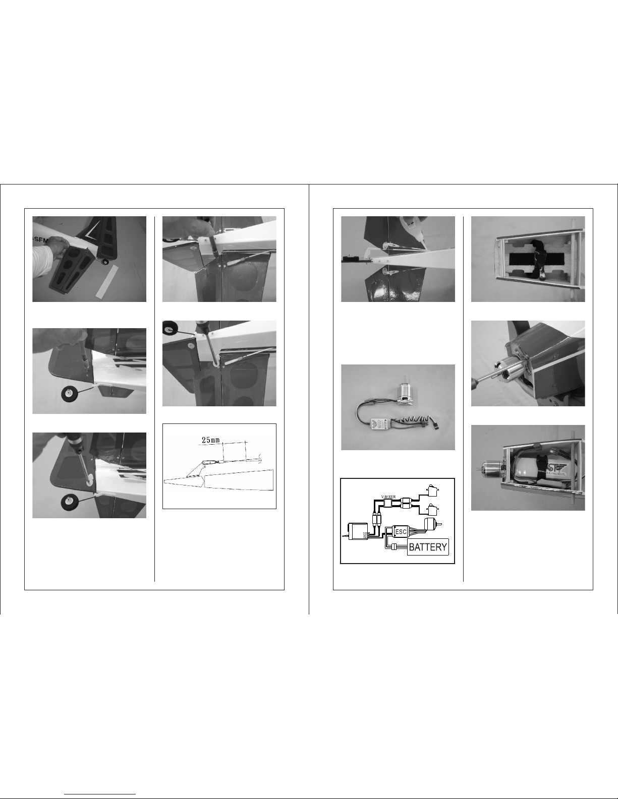
Using hobby knife, carefully cut the
covering inside the marking lines.
Please do not press hard enough to
cut into the wood as doing so could
weaken the horizontal.
Secure the stabilizer back temporary.
Assemble the tail gear with wheel and
plastic collar. Secure the collar with
M3x6 screw.
Secure the vertical on the horizontal
use epoxy. The vertical must be
perpendicular to the horizontal.
Repeat the same procedure to remove
the covering on the top of horizontal.
Slide the horizontal into the fuselage.
Use hobby knife to cut off the covering
on the vertical where it will meet the
horizontal. Please do not press hard
enough to cut into the wood.
Use hobby knife to open the slot on
the bottom of rudder for inserting the
tail gear.
Try to fit the rudder into the fuselage.
Spread epoxy on the bottom of the
horizontal where it meets the fuselage.
Use 2 pieces of 3x10mm tapping
screws to secure the tail gear on the
fuselage.
Suggest using UHU glue to secure the
top of the horizontal on the fuselage.
Page 5
7 8
Apply the supplied transparent tape on
the junction where the horizontal
meets the fuselage.
Drill 2mm holes on the bottom of
elevator for securing the control horn.
Diagram for the cables connection.
Drill 2mm holes on the rudder for
securing the control horn.
Place the control horn over the 2mm
holes and secure it with 2x13mm
screws.
Place the control horn over the holes
and secure it with 2x13mm screws.
Please leave 25mm space between
the pushrod tube and the clevis. Apply
some instant glue to secure the
pushrod tube on the fuselage.
Apply the hook and loop on the battery
tray.
Secure the motor on the motor mount
with 4 pieces of 3x10 tapping screws.
Apply a small piece of hook and loop
on the ESC. Install the battery pack.
Secure the ESC beside the battery.
Slide the rod into one piece of
supplied silicone tube, thread the
clevis on the end and connect with
control horn. Move the silicone tube
to the clevis for preventing loosening
during flying.
Assembly the motor with ESC.
Please note the rotating direction.
Page 6
9 10
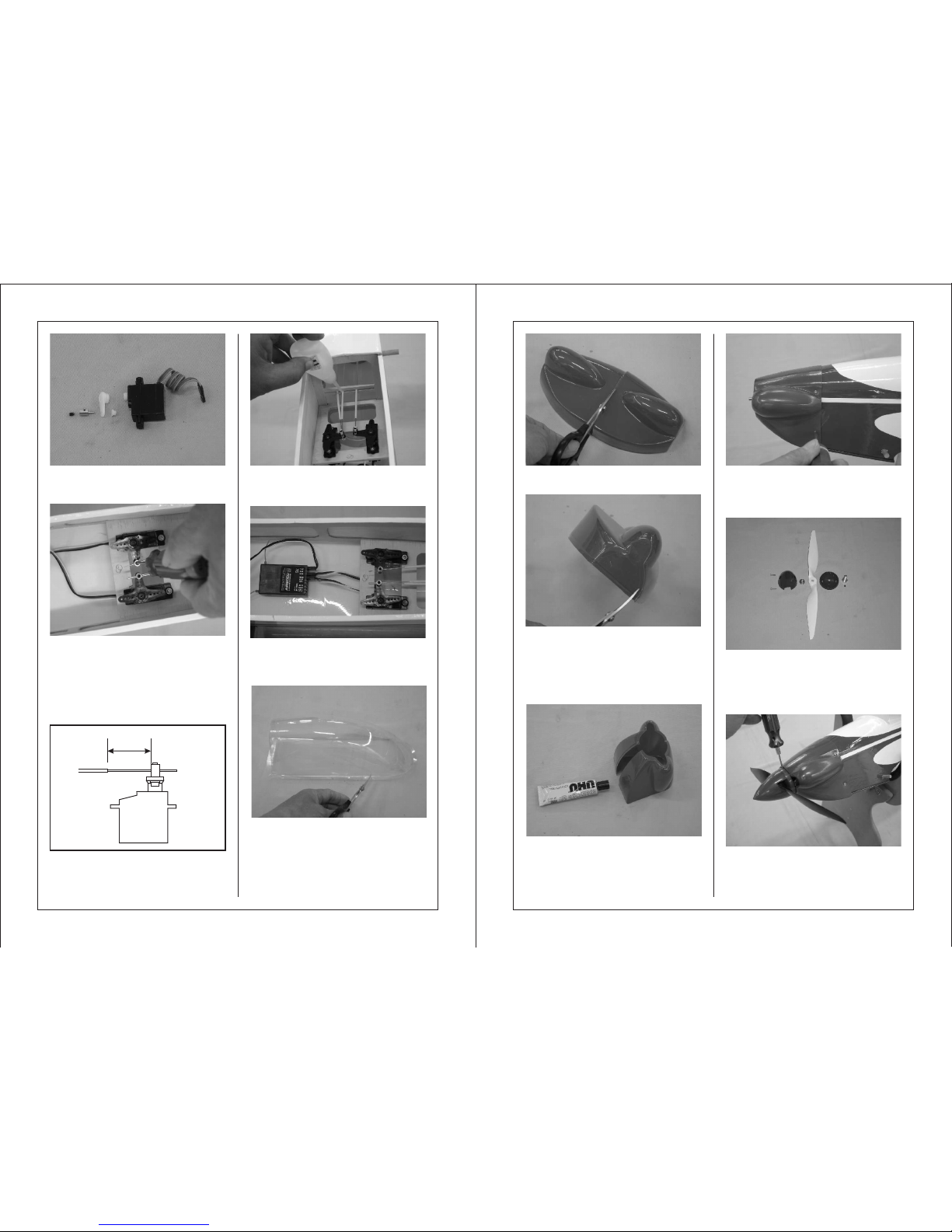
Place two 17g servos on the working
table. Assemble the rod connectors
on the servo arms.
Secure the 17g servos servo tray
(inside the fuselage) Slide the pushrod
wire through the pushrod connector.
Center the rudder and rudder servo.
Secure the wire using a 3x4 hex screw.
Repeat the same procedure for the
elevator servo.
Please leave 25mm space between
the pushrod tube and the pushrod
connector.
Pull the pushrod tube straight and
apply some instant glue to secure the
pushrod tube on the planking.
Secure the receiver using the hook
and loop strap.
Trim the canopy according to the
tooling line.
Trim the cowling according to the
tooling line for opening the hole
for motor and vent.
Suggest using UHU glue to secure
both cowlings together.
Try to fit the cowling on the nose.
When satisfy the position, use 4
pieces of 2x6 screws to secure the
cowling on the nose.
Assemble the spinner with propeller
using following accessories:
Spinner, Aluminum adaptor, Nut,
2 pieces of 3x10 screws,
11 x 5.5 propeller, 3x4 hex screw
Try to fit the spinner into the motor and
secure the spinner with 3x4mm hex
screw.
25 mm
Use hobby knife to cut the plastic
engine moulding separately.
Page 7
11
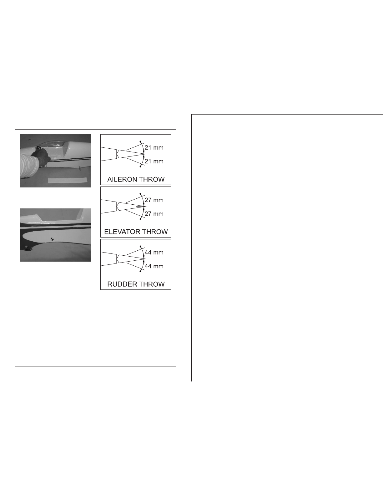
Try to fit the canopy on the fuselage.
When satisfy the location, apply the
supplied transparent tape to secure
the canopy in place.
Center of Gravity
The recommended Center of Gravity
location is 70mm back from the
leading edge against the fuselage.
 Loading...