

Page 1
No.8714
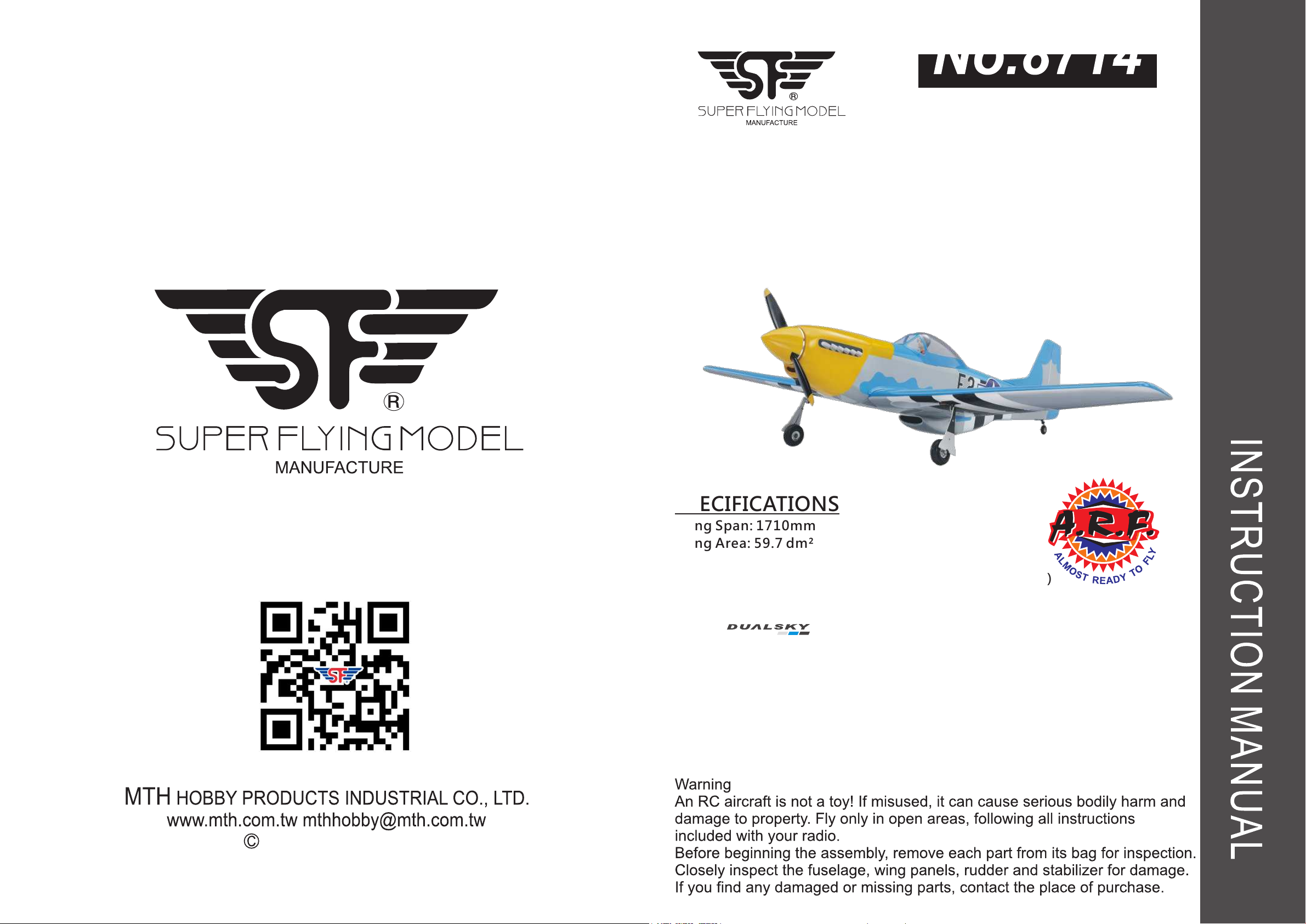
P-51D Mustang
SPECIFICATIONS
Wing Span: 1710mm
Wing Area: 59.7 dm²
Length: 1430mm
Total Weight: 3600g (with motor and battery 5000mAh)
Radio: 4 ~ 6(if use flap) channels
Motor: 560KV brushless
XM6350EA-6
Thrust: 4 KGS and up
Battery: Li-Po 6 cell 5000mAh and up
ESC: 100A
Engine: 20cc 2-stroke(Gas)
.90-.120 4-stroke
Propeller for EP: 16 x 10”
Propeller for GP: 16 x 10”(Gas)
Propeller for GP: 15 x 10”
MTH HOBBY 2016
Page 2
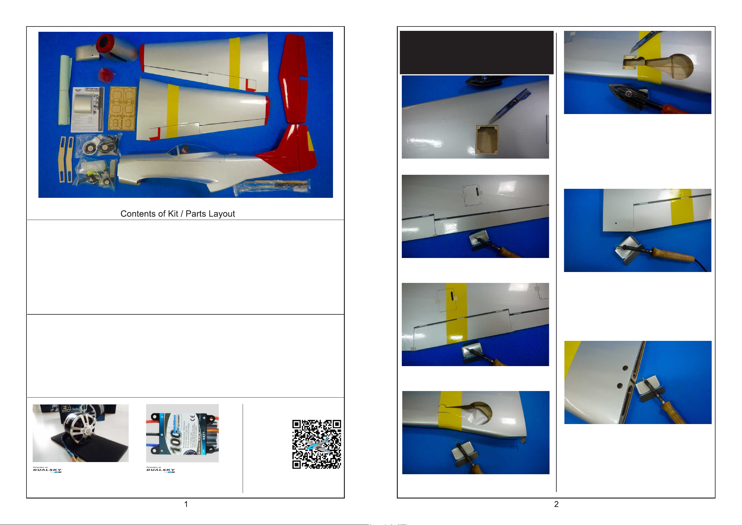
Please use sharp hobby knife
or soldering iron to remove the
covering.
Remove the covering out of the servo tray.
Remove the covering out of the retracts
mount and trim the edges with ironer.
Recommended radio and equipment (Not included in kit):
For GP version:
6 or up channel radio x 1 piece
Receiver x 1 piece
Servos (45g) x 7 pieces(or 45g x 6+9g x 1)
16x10" propeller x 1 piece
Y-harness x 3 piece
30cm Extension x 4 piece
For GP version:
6 or up channel radio x 1 piece
Receiver x 1 piece
Servos (45g) x 6 pieces
100 Amp or up brushless ESC x 1 piece
16x10" propeller x 1 piece
Y-harness x 3 piece
30cm Extension x 4 piece
Tools and suppliers needed (not included in kit):
1.5/2.0/3.0mm hex wrench
1mm/2mm driller
Driller 2mm/3mm/4mm/5mm
Shrinking tube
Z-bender
Sharp Hobby Knife
Sharp-nose pliers
Sealing Iron
Soldering Iron
Phillips PH0/PH1
Ruler
Marker and transparent tape
Side-cut pliers
5min Epoxy
30min Epoxy
Instant glue
Heat gun
UHU glue
Super glue
Remove the covering out of the slot on the
aileron's servo cover.
Remove the covering out of the wing fixing
hole.
Remove the covering out of the servo tray on
the flap.
XM6350-6 560KV
XM5050-8 535KV
Recommend ! !
XC10036HV V2
100 Amp brushless ESC
Color
manual
www.mth.com.tw
Try to find the exit hole for the servo line on
the main wing. Remove the covering out of
the hole.
Remove the covering of out of the main gear
mount.
Page 3
EP ONLY
For the EP version:
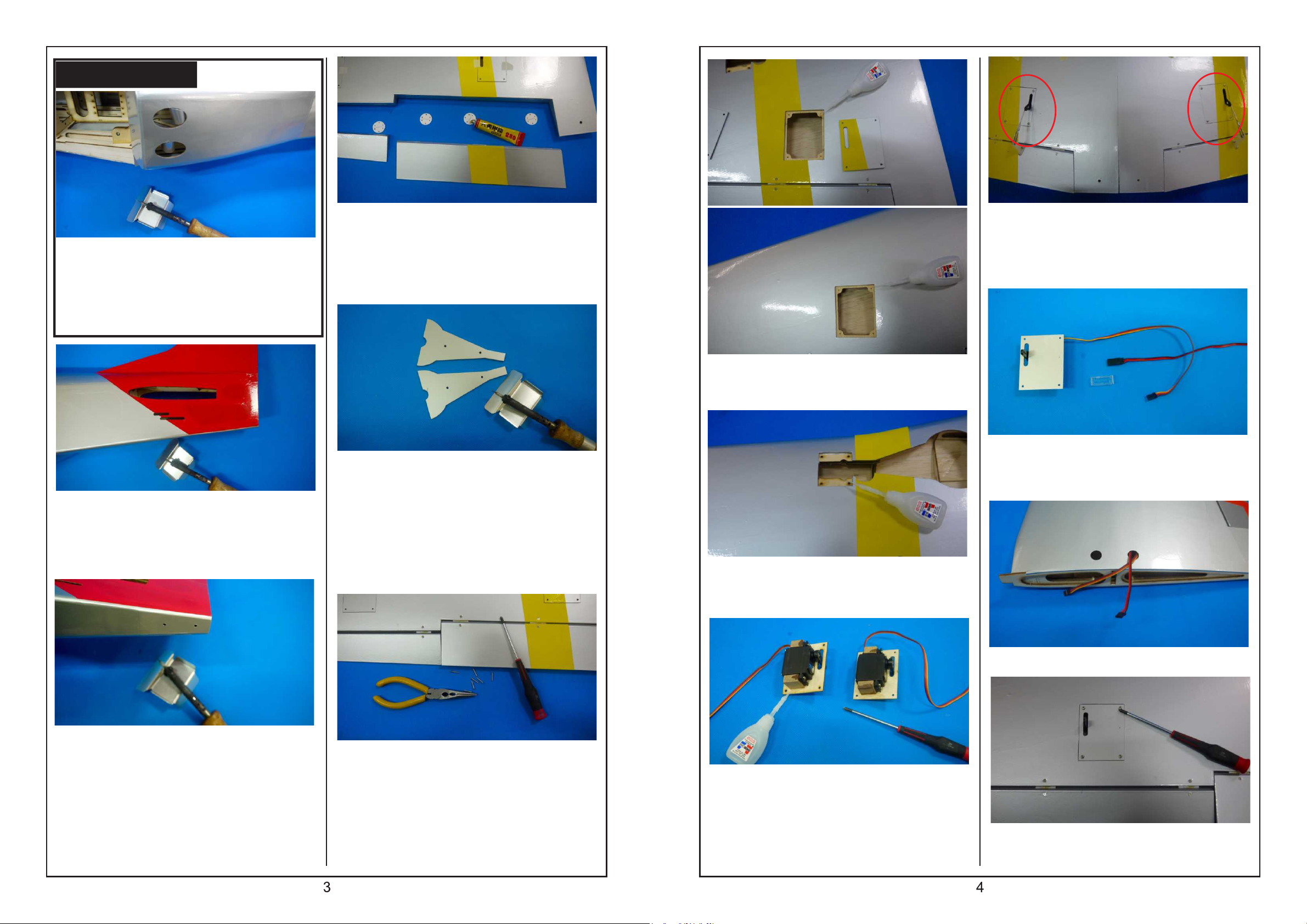
Place the fuselage upside down. Try to find
the location of venting hole. Remove the
covering out of the hole.
Try to find the rod holes for the horizontal
and rudder. Remove the covering out of the
holes.
Spread some Super Glue on the top and
bottom one-half of each hinge. Insert the
hinges into the main wing until the hinge line
is even with the trailing edge of the main
wing.
Place the gear cover on the working table.
Find the screw holes on the cover. Remove
the covering out of the screw holes.
If use Y-harness on the flap, please install
the left wing and right wing servos at the
same side. If want to use mixer on the radio,
the location of both servos must be on
different side.
Drop some instant glue into the screw holes
for the servo tray.
When connect the extension or Y-harness
with the servo, please apply some tapes on
the connections for avoiding losing off during
flying.
Place the fuselage upside down. Try to find
the screw holes for the tail gear mount.
Remove the covering out of the screw holes.
Spread some Super Glue to the remaining
half of each hinge and place the aileron and
flap onto the main wing. Secure the hinges
with 2x15mm tapping screws. If the end of
the screw is too long, use side-cutter to trim
the end.
Drop some instant glue into the screws holes
on the retracts mount.
Try to place the servo on the servo planking.
Use instant glue to secure the servo planking
on the cover. Set the servo arm to the center
exit. Secure the servo in place with screws
coming with servo.
Pull the servo line out of the exit hole.
Secure the servo cover in place with M2.6x8
tapping screws.
Page 4
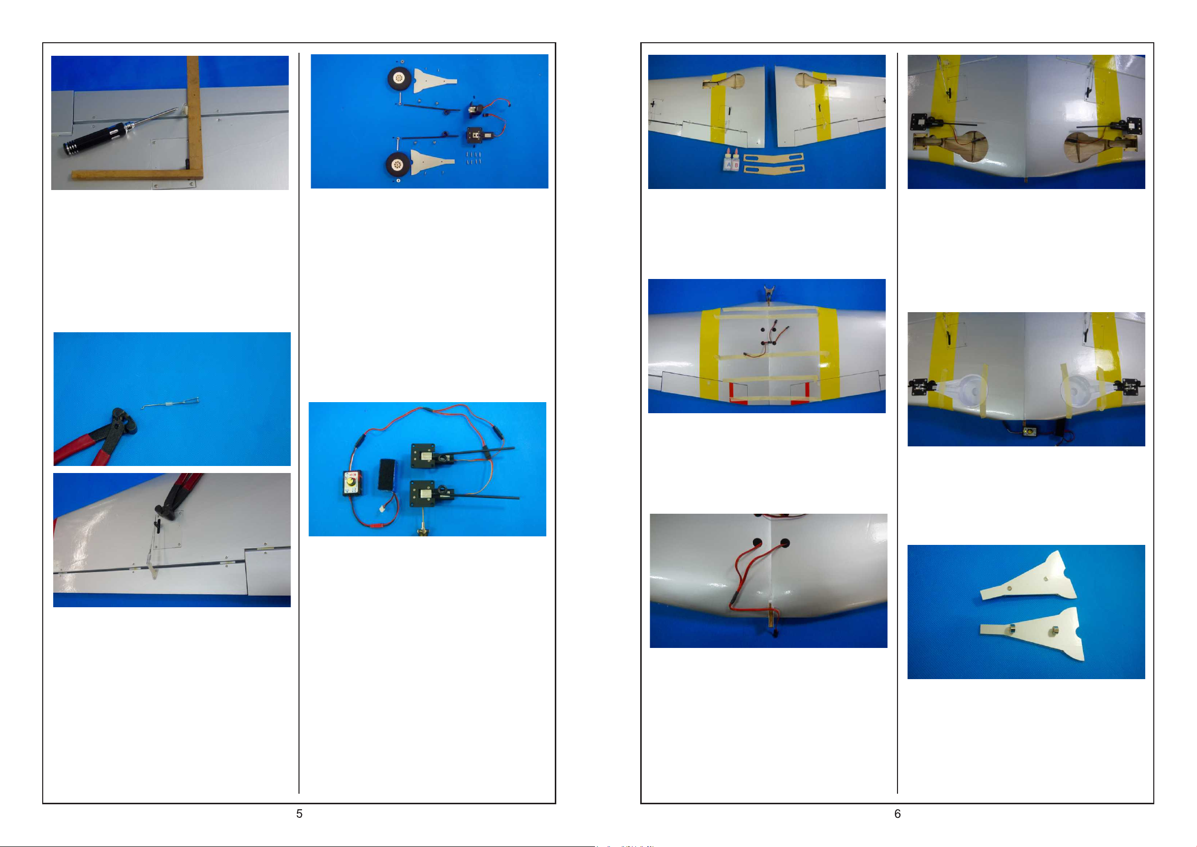
Place the triangle rule along the servo arm to
the trailing edge for setting the location for
installing the control horn on the aileron. Use
1.5mm hand driller to drill holes for the
control horn. Place the control horn in
position and the strap on its back and secure
with M2x25mm screws.
Place the accessories for the main gear on
the working table:
70mm round sponge wheels x 2 pieces
4mm collar x 6 pieces
axle x 2 pieces
M3 x 4 flat-head hex screw x 4 pieces
M3 x 8 flat-head hex screws x 2 pieces
wheel paints x 2 pieces
retracts x 2 pieces
left main gear x 1 piece
right main gear x 1 piece
Spread generous amount of 30-min epoxy to
the top and bottom of wing joiners, and wing
root. Insert the wing joiners to the left and
right main wing for securing both main wing
together.
Use tapes and clip to hold the main wing set
temporary until the glue is dried enough.
Use tissue to wipe away the excess glue.
Place the main wing upside down. Try to find
the Y-harness from the main gear mount.
Plug the Y-harness and apply some
transparent tape around the plug. Assemble
the retracts on the main wing with M3x12
tapping screws.
Turn on the power and set the gear down.
Install the vacuum-formed mounts for wheels
on the main wing and secure them in place
with instant glue.
Thread the clip to the rod. Slide one piece of
5mm silicone tube to the connection of the
control horn and clip. Use Z-bender to make
a Z bend on the rod for connecting with servo
arm.
Caution: left main gear is different from right
main gear. For identification, please set the
gear up, secure the gear to retracts with
M3x8 hex screws (the flat side of the gear
must face the side screw holes of retract.
Pull the Y-harness from the retracts to the
wire exit.
Use M3x6 flat-head screws to secure the
collars on the wheel covers for temporary.
Don't screw too tight.
Page 5
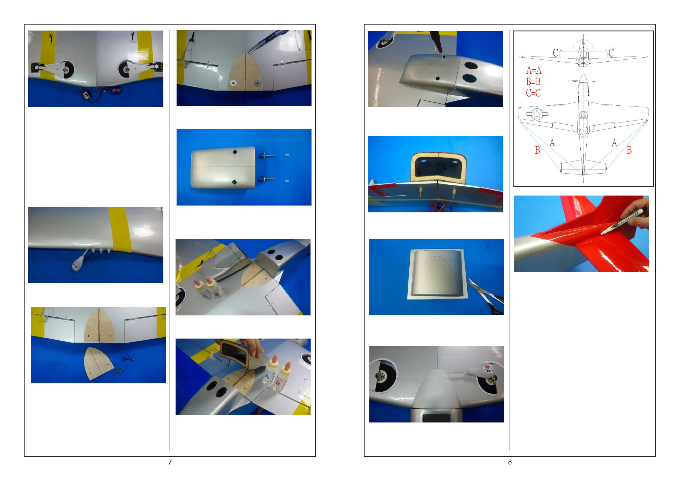
90
o
o
90
Assemble the gear covers to the gear
mounts. Secure the axles to the main gear
with M3x4 screws. Install the wheels and
collars.
Turn on the power and set the gear up. Try
to adjust the positions for wheels and gear
covers. When satisfy the location, secure
them in position with the screws. (It is normal
that the screws will push the gear cover
when the screws are tight.)
Use sharp hobby knife remove the covering
inside the planking area carefully.
Place the venting M4x35 wing bolts (hex),
washers and silicone tubes on the working
table.
Secure the wing bolts for temporary until the
epoxy is dried enough.
Insert the silicone tube to the end of
wing bolt.
Use instant glue to secure the machine guns
on the main wing.
Place the main wing upside down. Take the
reinforcement planking out of the hardware
bag. Try to place the planking along the
trailing edge and set its center line on the
center line of main wing. Use screws to hole
the planking in place for temporary.
Spread some epoxy on the area where the
covering was removed on previous step.
Insert the wing bolts and washers through
the venting. Try to the fit the vent onto the
main wing with the wing bolts into the bolt
holes.
Take the vacuum formed aerodynamics out
of the hardware bag. Use scissors to trim the
part along the line.
Try to place the aerodynamics on the leading
edge of the center main wing. Sue instant
glue to secure it in place.
Remove the elevator out of the horizontal.
Trial fit the horizontal in place on the
fuselage. Please note the distance to the tip
of the horizontal must be equal on both
sides. Please refer to the last drawing. When
you are satisfied with the alignment, use
marker to carefully trace around the top and
bottom of the horizontal where it meets the
fuselage.
Page 6
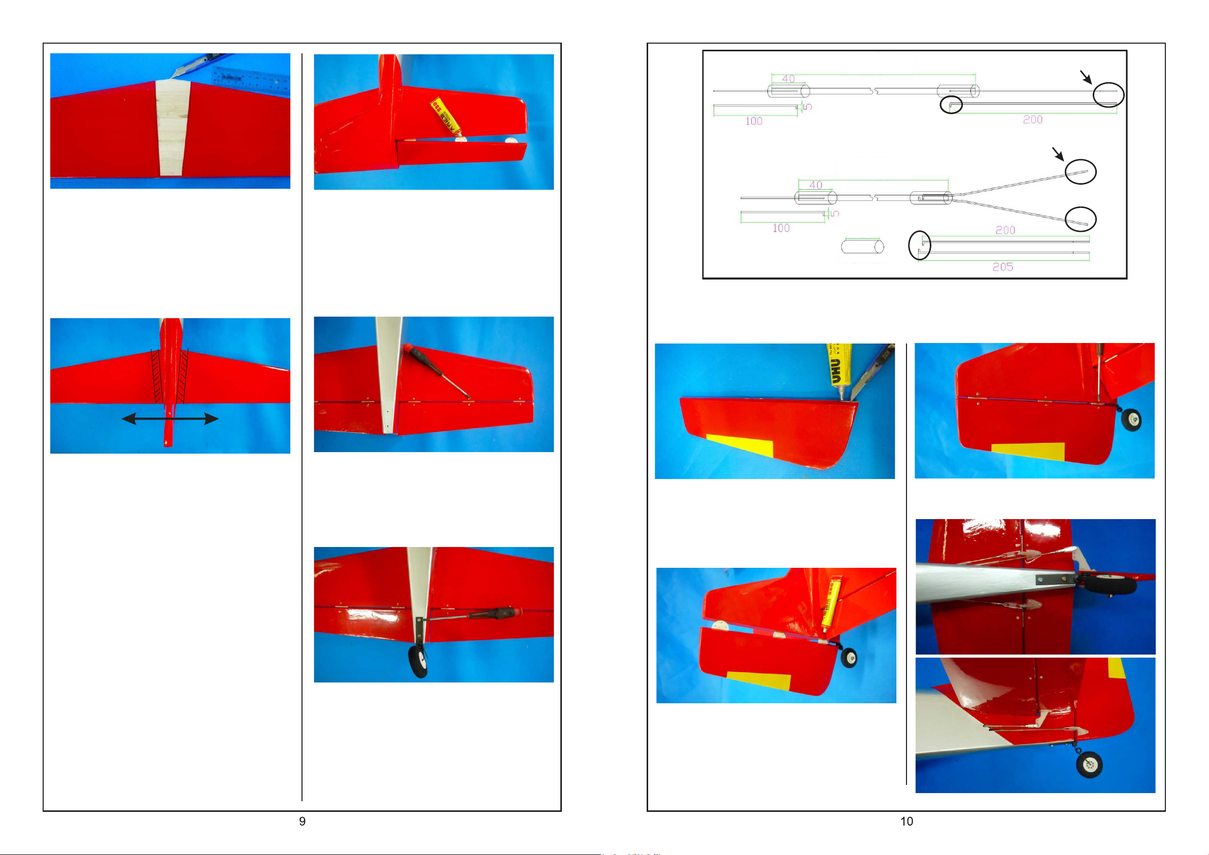
RUDDER 395mm
5mm 90
5mm 90
Threaded end
o
o
Remove the horizontal from the fuselage.
Using a sharp hobby knife carefully cut away
the covering inside the marking area. Do not
cut into the balsa wood as this will affect the
structural integrity of the horizontal.
1. 2.
Use Super glue to secure the hinges insides
the hinges slot of elevator. Also use Super
glue to secure the half of hinges to the
horizontal.
ELEVATOR
Threaded end
330mm
40mm
5mm 90
shrinking tube
Please follow the following drawings to assemble the rods. Insert the 90-degree bend into the
hole of the pushrod dowel and saturate the dowel with instant glue where the rod contacts
the dowel. Allow to cure. Slide a piece of heat shrink tubing over the end of the pushrod
dowel and use a heat gun to shrink it in place over rod/dowel connection.
o
Two ways to glue the horizontal to the
fuselage:
a. Fit the horizontal to the fuselage. Spread
generous amount of epoxy on the area
where the covering was removed on top and
bottom. Move the horizontal from the left to
the right several times, so the epoxy will
move into the fuselage. Set the horizontal to
the correct position, wipe off the extra epoxy
and wait until the glue is dried enough.
b. Fit the horizontal to the fuselage. Inject
generous amount of instant glue to the
conjunctions and wait the glue to dry.
Use 2x15mm tapping screws to secure the
hinges. Use side-cutter to remove extra
length of screws.
Secure the tail wheel to the tail gear. Use
M3x10 tapping screws to secure the tail gear
mount to the tail.
Try to find the slot on the rudder for installing
the tail gear. Use sharp hobby knife to
remove the covering out of the slot. Spread
UHU glue or epoxy into the slot.
Spread Super glue on the one half of hinges
and insert the hinges to the hinge slots on
the rudder. Spread Super glue on the other
half of hinges and insert the hinges to the
slots on the vertical.
Secure the hinges in place with M2x15
tapping screws.
Page 7
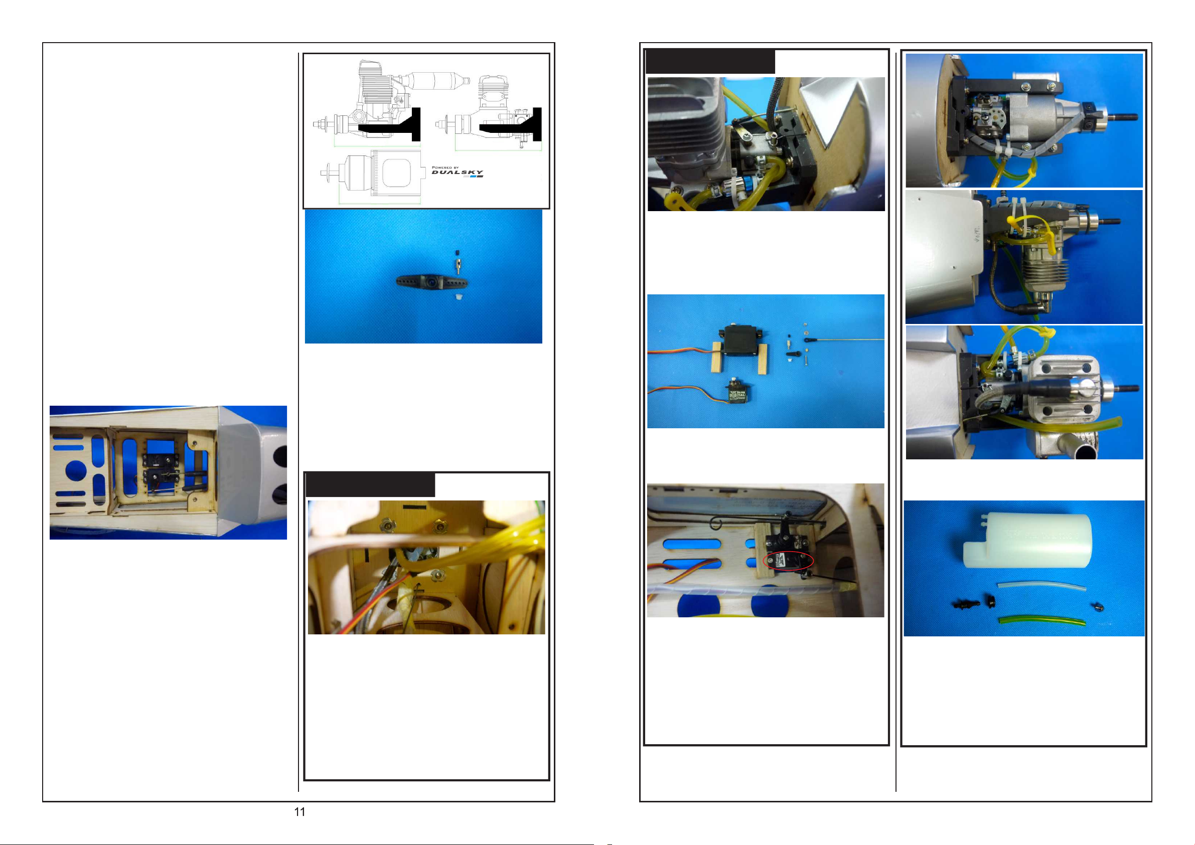
1) Take 1200mm transparent tube out the
hardware bag. Cut the tube into two pieces
from the center. Slide the tube from the rod
opening on the fuselage, through the
fuselage and to the rod opening of the tail.
2) Cut 3 pieces of 60mm transparent tube.
Slide the one pieces of rudder rods and two
piece of elevator rod into the tubes.
3) Slide one piece of 5mm silicone tube to
the rod and thread the metal clip to the end
of rod.
4) Pull the rod straight. Mark the locations for
installing the control horn on rudder and
elevator where the straight rods meet the
rudder and elevator. Secure the control horns
on the marked locations with M2x25mm
screws.
5) Adjust the metal clips for connecting the
control horn properly. Slide the silicone tube
over the connecting place.
6) Keep the distance between the end of the
transparent tube and the metal clip around
30mm and drop some instant glue to secure
the transparent tube to the fuselage. Make
sure the movement of the rods will be freely.
.91-.120
155mm
XM6350-6
145mm
Following are the steps for assembling
adjustable rod stand:
1) Drill 2mm hole on the servo arm.
2) Insert the metal clip to this hole and
secure it in place with plastic nut.
3) Insert the rod to the stand and secure it
in place with M3x4 hex screw.
Gas 20cc
155mm
GP ONLY
Connect the throttle rod with ball-end.
Secure with M2x15mm screw and plastic
nut. Connect the ball-end rod with throttle.
Connect the rod for Choke with adjustable
rod stand.
The servo for the throttle can be standard or
mini servo.
1) Use 2.0mm hand driller to open holes for
the screws on the servo arm. Screw the
adjustable rod stand and plastic nut to the
servo arm. Make sure the rod stand can
move freely.
2) When install the servo for elevator; please
set its servo arm to the center of the
fuselage.
3) Secure the servo to the servo tray with the
screws coming with servo Insert the rod to
the adjustable rod stand, set the servo to its
neutral position and secure with M3x4 hex
screws.
GP ONLY
Push the claws nails to the holes inside the
fuselage. It's better to use the engine screw
M4x30 hex screw to secure the claws nails
hard into the planking. Drop instant glue
around the claws nail for securing it in
place. Don't let the instant glue touch the
screw.
1.
2.
Choke control :
1) Use 1.2mm rod pulling to the fuselage
and use hand to open it.
2) Use another servo to operate.
Diagram for assembling the tubing and
linkage of the engine.
Please take the picture as a reference and
assemble the fuel tank combination. If equip
with gas engine, please select the yellow
fueling tube.
12
Page 8
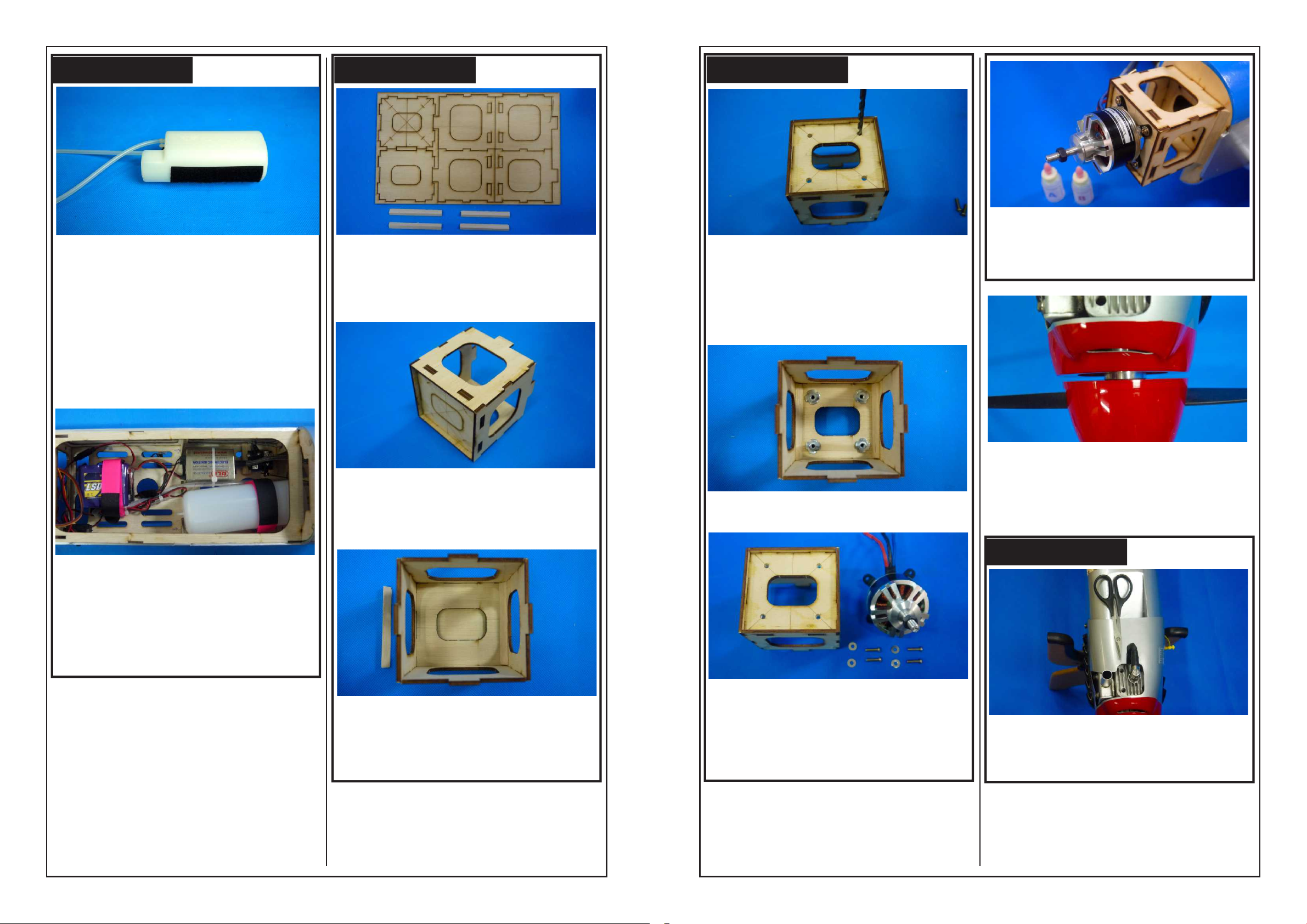
GP ONLY
Connect the feed-line tubing and vent-line
tubing to the fuel tank. Please purchase
correct tubing for the engine.
Apply a piece of adhesive Velco tape on the
bottom of fuel tank and another Velco tape
on the battery tray.
EP ONLY
Take the laser cutting planking out of the
hardware bag and place on the working
table.
EP ONLY
Try to fit the motor onto the motor mount.
When satisfy the location, use marker to
mark the position for the screws. Remove
the motor and use hand driller to open
holes on the marked positions.
Use Epoxy to secure the motor mount on
the fuselage and reinforcing blocks on two
sides of moor mount.
Use Velcro tape to secure the tank and
receiver inside in fuselage.
Remove every part out of planking and
assemble the parts into motor mount. Use
instant glue to secure the parts.
Use wood glue to secure the reinforcing
block on the bottom of motor mount.
Spread Epoxy on every corner for
reinforcement.
Push claws nails into the opened holes.
Use m4x20 hex screw to secure the claws
nails into the holes. Drop some instant glue
around the claws nails, not the screws.
Assemble the spinner with propeller. Install
the spinner to the motor. Please keep the
distant between spinner and cowl around
2mm.
GP ONLY
If use GP; please use scissors to trim the
cowl for meeting the outline of the engine
before securing the cowl to the fuselage.
13
14
Page 9
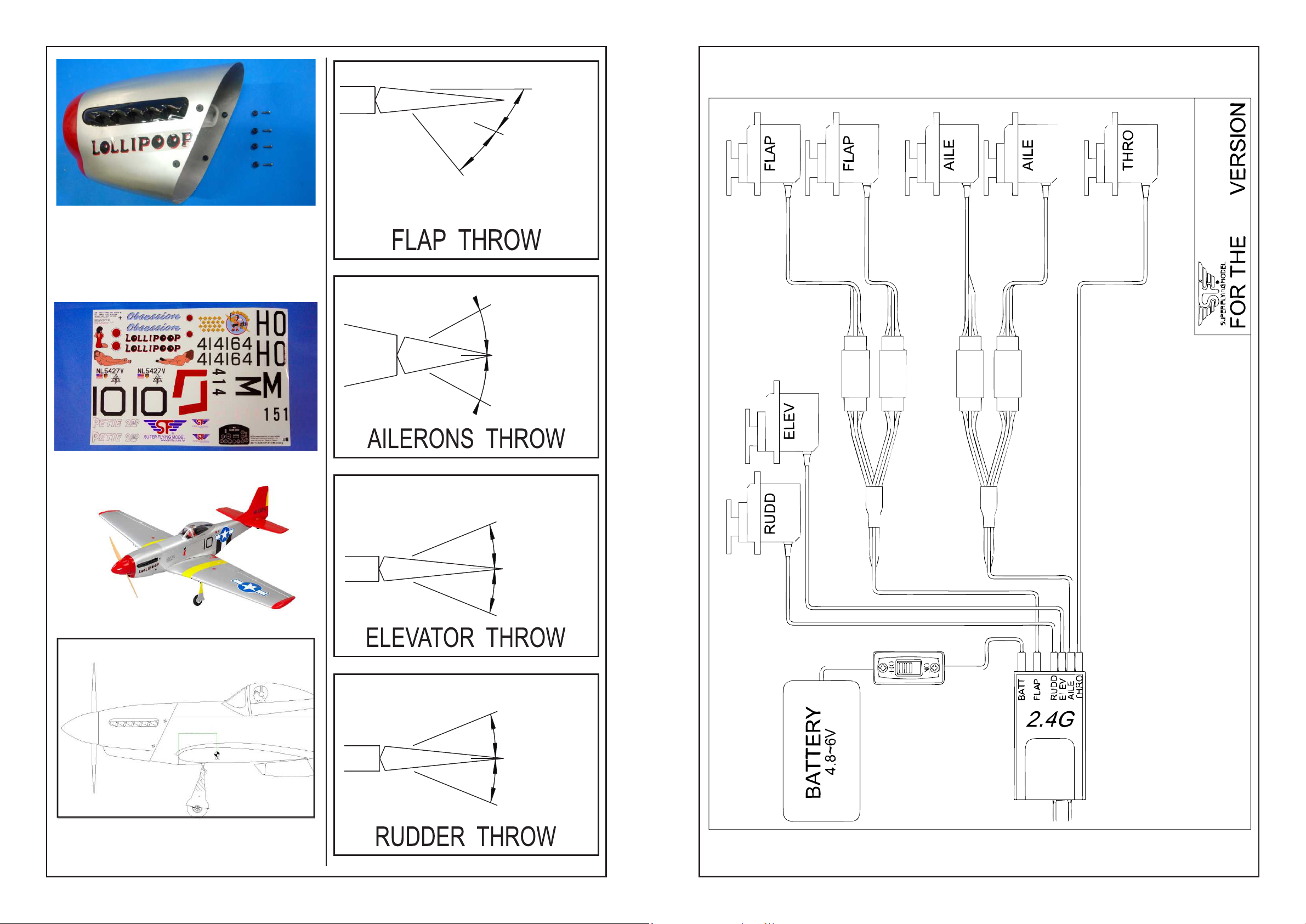
Installing the anti-vibration rubber inside the
cowl. Try to fit the cowl to the motor or
engine. When satisfy the location, use
M2.6x12 tapping screws to secure the cowl
in position.
Tack off
o
30
Landding
o
45 or more
GP
15mm
15mm
Apply your favorite stickers!
Finish !!
120mm
20mm
20mm
22mm
C.G. The recommended Center of Gravity
location is 120mm back from the leading
edge against the fuselage.
15
22mm
16
Page 10
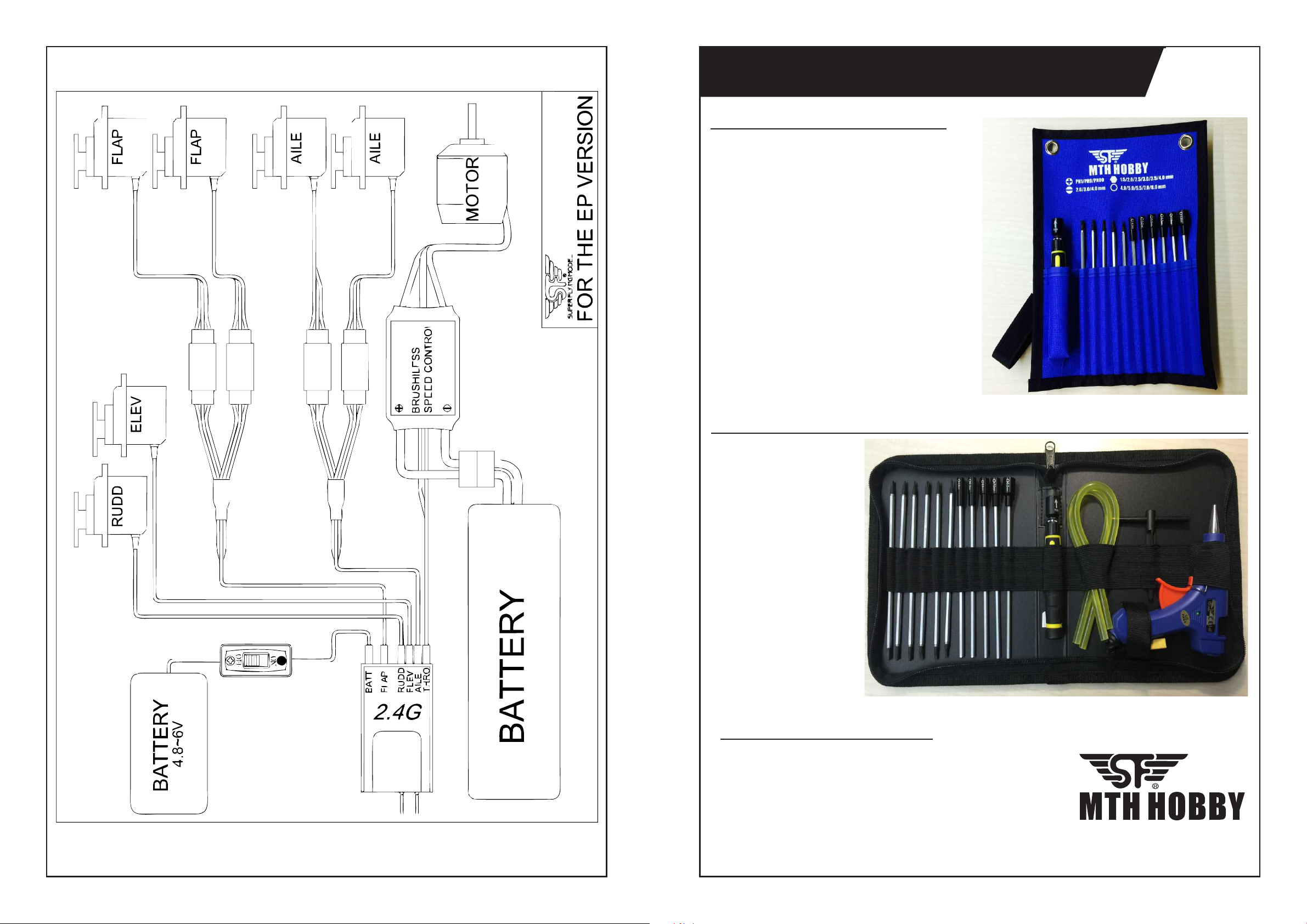
The Best Recommendation for Assembly
17 IN 1 Tool Pouch Set
Plastic Extendable Gearless Precision
Screwdriver
High-carbon steel Replaceable Tips
SPECIFICATION:
Nut Drivers:
4mm,5mm,5.5mm,7mm,8mm
Hex1.5 x Hex3.0
Hex2.0 x Hex3.5
Hex2.5 x Hex4.0
(-)Slotted 3.0 x (+)Ph0
(-)Slotted 4.0 x (+)Ph1
(-)Slotted 2.0 x (+)Ph00
Item:
#5002-1
Item:
#5005
High Quality
Canvas Zip Bag
Plastic Extendable
Gearless Precision
Screwdriver &
Propeller Reamer
High-carbon steel
Replaceable Tips
Glue Gun and Glue
Stick
17
20 pcs Tool Pack
SPECIFICATION:
Glue gun: 3S-11.1V (included TX-60 Socket)
Propeller Reamer: 5mm,6.5mm,8mm,9.5mm
Nut Drivers: 4mm,5mm,5.5mm,7mm,8mm
Hex1.5 x Hex3.0 (-)Slotted 3.0 x (+)Ph0
Hex2.0 x Hex3.5 (-)Slotted 4.0 x (+)Ph1
Hex2.5 x Hex4.0 (-)Slotted 2.0 x (+)Ph00
The Excellent Tools Supplier
 Loading...