

Page 1

MTH HOBBY PRODUCTS INDUSTRIAL CO., LTD.
www.mth.com.tw [email protected]
MTH HOBBY 2013
Warning
An RC aircraft is not a toy! If misused, it can cause serious bodily
harm and damage to property. Fly only in open areas, following all
instructions included with your radio.
Before beginning the assembly, remove each part from its bag for
inspection. Closely inspect the fuselage, wing panels, rudder and
stabilizer for damage. If you find any damaged or missing parts,
contact the place of purchase.
INSTRUCTION MANUALINSTRUCTION MANUAL
NO.8709/8710/8712
Page 2
1
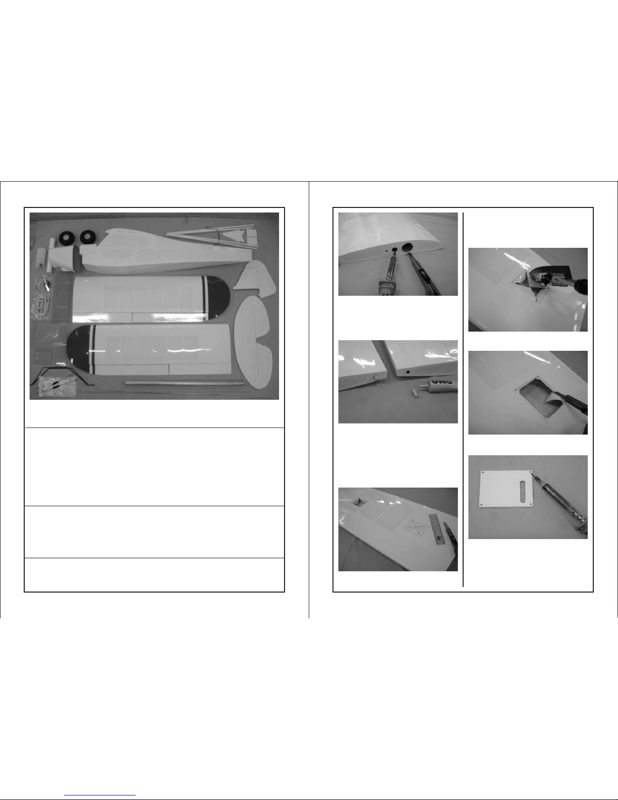
Contents of Kit/Parts Layout
Tools and suppliers needed (not included in kit):
Phillips screws driver #0/#1 / Curved scissors / Hex wrench 1.5/3.0mm
Hobby knife / Ruler / Pliers / Z-bender / Sanding paper
Epoxy 5-10 minutes / Marker / CA glue / UHU foam glue / Superglue
Cross wrench / Reamer / Solder Iron / Thread lock / Side Cutter
Driller 1.2mm/4mm / Transparent Tape
2
Recommended radio and equipment (not included in kit):
6 channels radio x 1 piece Y-harbess x 3 pieces
Receiver x 1 piece Switch x 1 piece
45g servo x 6 pieces ( 8 if use flap) Spinner x 1 piece
30cm extension x 2 pieces
60cm extension x 4 pieces
Engine: 26cc - 30cc 2-stroke
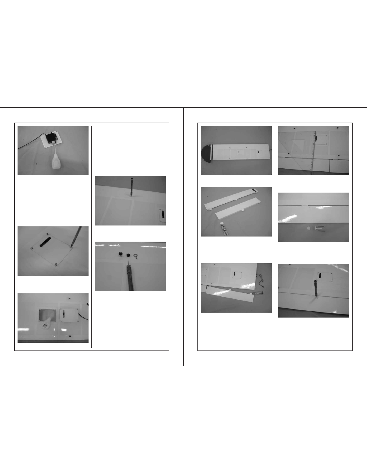
Using a sharp hobby knife carefully
cut the covering away from each of
the holes on the main wing. Use the
solder iron to trim the covering
around he holes.
Take 2 pieces of 7 x 18mm dowels
out of the hardware bag. Sand the
end of the dowels, spread some
UHU glue on one half of the dowels
and insert the dowels (with glue on)
into each of the wing
dowel holes.
There are pre-serving servo trays on
the bottom of the main wing. Mark
Use solder iron to trim the covering
around the holes.
Use hobby knife to cut away the
covering around the servo holes.
two diagonals of a square cross in
the center of the hole. Use a hobby
knife to cut the covering
according to the marking lines.
Take the servo tray planking out of
the hardware bag and use driller to
open holes on the 4 corners.
Please note :
For control lin g the e lev ato r, one end of the ext ens ion m ust c onn ect with
the receive r; th e oth er en d hav e to connect wit h AUZ ho le of t he mi xer
for adjusti ng th e cor rec t mov ement.
Contents of the kit / Parts layout..
Page 3
3
4
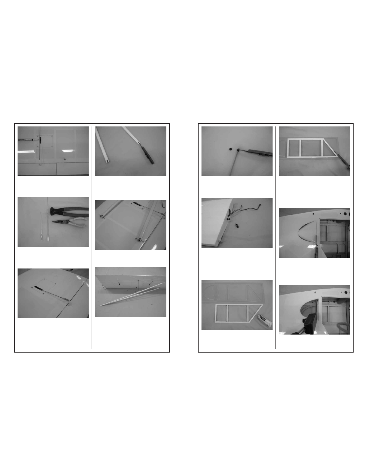
Connect the servo with the receiver
and set the servo to the neutral
position. Set the servo arm to the
exit hole and place the blocks on two
sides of the servo (if the blocks are
too large, use sanding paper to trim
the length). Drop some CA glue to
secure the blocks in position. Secure
the servo in position with the screws
supplied with the servo.
Place the servo tray in position and
try to secure it with 4 pieces of 2.6x
10mm tapping screws.
and remove the servo tray and drop
some CA glue into the screw-holes
for reinforcement. (Note: aileron
servo must connect with 60cm
extension. Flap aileron connects
with 30cm extension. It is convenient
to use the outer tube included in the
hardware bag and a piece of tape to
secure the plug on the tube and pull
out the plug of the extension.)
Use 1.2mm driller to drill 4 holes on
the pre-marking locations on the main
wing.
Take 10 pieces of eye-screws and
rubber eyelets out of the hardware
bag. Stuff the eyelets into the eyescrews.
Screw the eye-screws into the 4
holes.
Place the aileron and flap on the
working table. Spread some
superglue on one half of the hinges
and insert into the hinge holes on the
aileron and flap.
Spread superglue on another half of
the hinges and slide into main wing.
Apply transparent tape on the
conjunction until the glue dry enough.
Use a ruler aligned the edge of the
servo hole making a mark on the
edge of the aileron.
Remove the control horn and plate
from the plastic parts and take out the
M2 x 25mm screws from the
hardware bag.
Lose the tapping screws (2.6x10mm)
Place the control horn on the marking
position and use 2mm driller to drill
the hole. Secure the control horn and
plate in position with M2 x 25mm
screw.
Page 4
65
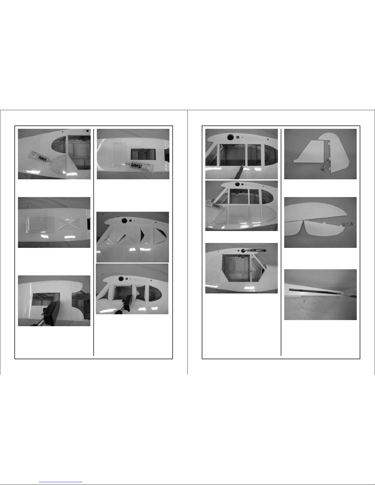
Thread the metal clip onto the rod.
Connect the clip with the control horn.
Use marker to mark the position
where rod contact with servo arm.
Use Z-bender to make a Z bend on
the marked position and cut off
the extra rod. Slide in one piece of
5mm silicone tube.
Connect the Z end with servo arm
and move the silicone tube on the
clip for avoiding losing off during
flying.
Connect the end of wing strut with
eye screw on the main wing and
secure with R pin.
Take the main wing strut on the
working table. Use a hobby
knife to cut off the covering
over the slot.
. Connect the ends of the wires with
eye-screws.
Take the rubber ring (3x10mm) out of
the hardware bag. Insert the rod into
the rubber ring and use hobby knife
to cut the ring into two halves.
Take 4x20mm hex screws and
washers out of the hardware bag.
Slide the washer into the screw and
insert the screw into the rubber ring.
Screw the whole rubber ring
combination into the main wing.
Spread UHU glue on the window
frame and glue the window frame on
the vacuum formed plastic window.
When the glue is dried enough, use
hobby knife to remove the extra
plastic window. Use curved scissors
to trim the rear window and keep
5mm extra plastic around the edge
of the rear window when trimming.
Use hobby knife to cut off the
covering over the opening for the
rear window and please keep 6mm
extra covering around the edge of
the opening when cutting.
Use sealing iron to trim the extra
covering inside the fuselage.
Page 5
7
8
Spread UHU glue on the edge of the
plastic rear window and fit it onto the
window hole inside the fuselage.
Use hobby knife to cut off the
covering over the opening for the
sunroof and please keep 2mm extra
covering around the edge of the
opening when cutting.
Use iron to trim the extra covering
inside the fuselage.
Use curved scissors to trim the edge
of the sunroof and please reserve
5mm extra plastic around the edge of
the sunroof. Spread UHU glue on the
edge of the sunroof. Fit the sunroof to
its opening from inside fuselage.
Repeat the same procedure on the
left side window set.
Try to find the pre-serving holes over
the top of the side window. Use
hobby to remove the covering over
the holes.
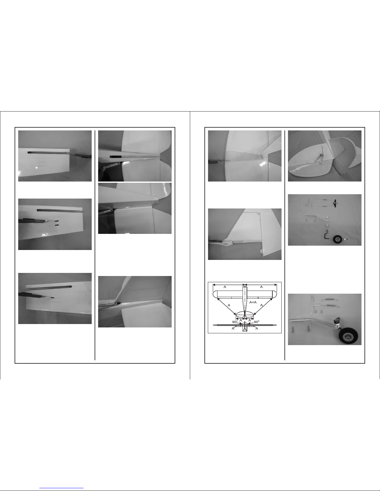
Place the vertical and rudder on the
working table. Spread superglue on
the hinges and slide into the rudder.
Place the horizontal and elevator on
the working table. Spread superglue
on the hinges and slide into the
elevator.
Try to find the pre-serving slot on the
tail of the fuselage for the vertical.
Use hobby knife to remove the
covering over the slot.
Page 6
9 10
Use hobby knife to remove the
covering over the slot for the elevator
and the block on the tail.
Try to find two linkage openings on
the tail of the left fuselage. Use
hobby knife to remove the covering
over the openings.
Try to find the top linkage opening on
the tail of the right fuselage. Use
hobby knife to remove the covering
over the opening. (This is only for the
top linkage hole.)
Use ruler to mark a center line on the
horizontal. Try to fit the horizontal on
the tail of the fuselage. The center
line must be in the center position of
the tail. When satisfy the location,
use marker to mark the contacting
area on the horizontal on both two
sides.
Try to install the vertical on the tail
and use marker to mark the
contacting area on the vertical.
Remove both vertical and horizontal.
Use hobby knife to cut off the
covering inside the marking area on
the horizontal (two sides). Please
don't cut into the wood.
Use hobby knife to cut off the
covering inside the marking area on
the vertical. Please don't cut into the
wood.
Use epoxy to glue the vertical and
horizontal in position.
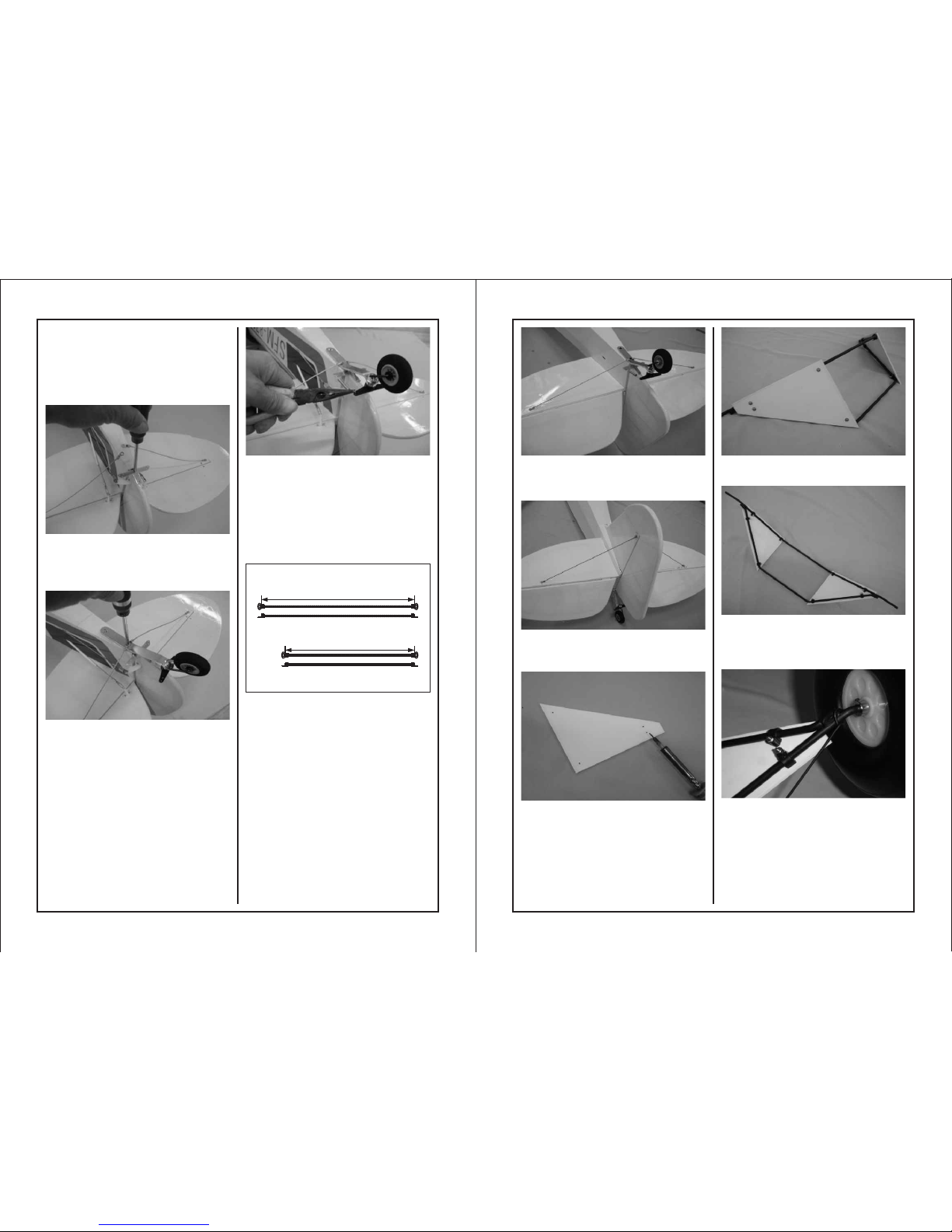
Take out the followingaccessories
from the hardware bag:
/ / Tail gear T-stand Wire
3mm Collar Aluminum blot w/nut /
Control Arm /Suspension (2 pieces)
3x16 Tapping screws (2 pieces)
2x12 Tapping screws (2 pieces)
Aluminum Collar Tail wheel /
3x4 Hex screws (2 pieces)
Assembling tail gear with stand and
secure it with the screws. Insert the
aluminum collar, tail wheel and 3mm
Page 7
11 12
Take the springs out of the hardware
bag. Use pliers to bend one end for
installing on the T-stand. Pull another
end to lock into control arm. Please
note that the strength on both springs
must be the same or the tail wheel
and rudder will be affected. Cut off
the extra length on the springs.
Try to locate the T-stand on the
bottom of the rudder. Center its
position and secure it with 2x12mm
tapping screws.
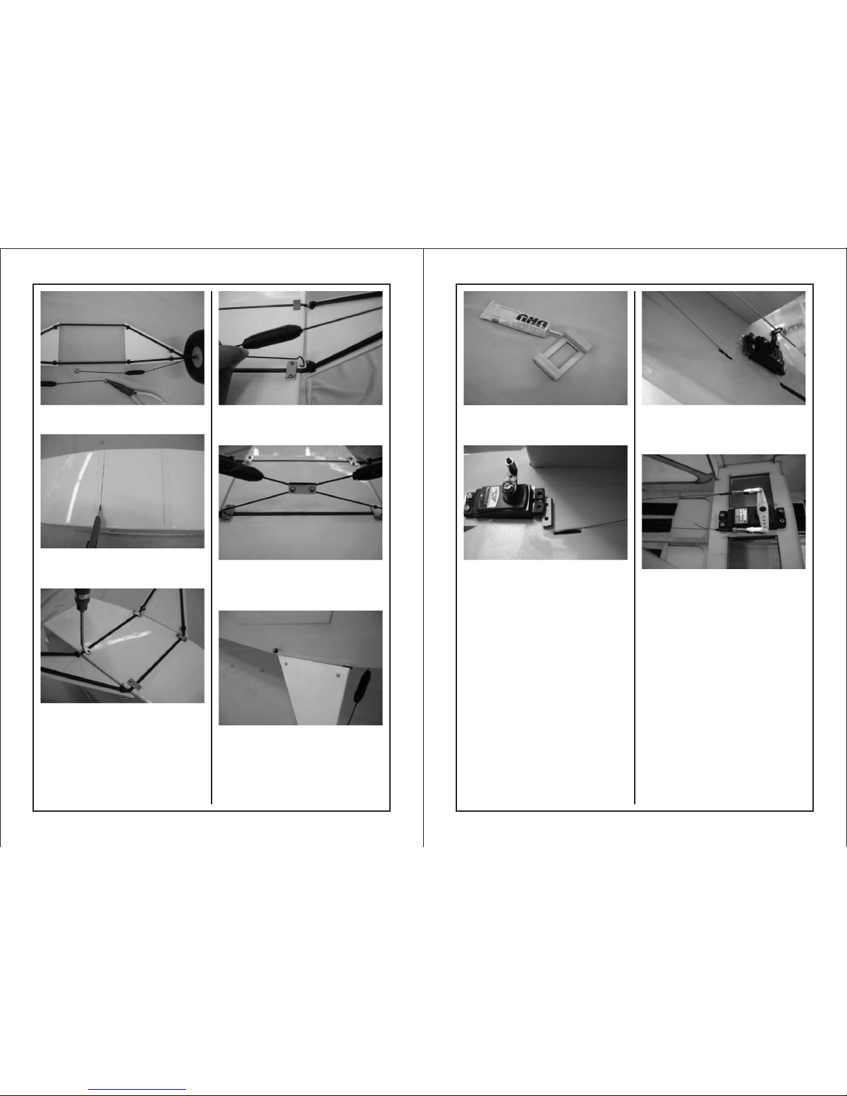
Place the tail gear assembly on the
bottom of tail gear. Please note the
direction. The bend end is facing the
T-stand. Secure the front end of tail
gear assembly with one piece of
3x16mm tapping screw on the
fuselage. Place the bottom wiring
assemblies on the tail gear.
Secure the both ends with tail gear
on the end of fuselage with 3x16 mm
screws.
Use plier to cut the wire into two
pieces. One is 263mm (for the top),
another is 222mm (for the bottom).
Connect the ends with connectors
and press into flat. Drop some CA on
the conjunction for reinforcement.
The location for securing the wires on
the horizontal and vertical.
263
222
Use 2mm nut and washer to secure
the screw though the bottom of the
fuselage.
Use 2 x 15mm screw to secure the
ends of the wire on thevertical and
horizontal.
Try to find the pre-serving 4 holes on
the main gear decoration planking.
Use driller to drill off the covering
over the holes.
Insert the M2x15mm screws and
2mm washers to the holes.
Take 8 pcs of plastic fixtures out of
the hardware bag and secure the
planking and the main gear with 2mm
nuts.
collar into the tail wire. Secure the
assembly with 3x4mm hex screw.
Fasten the tail wheel assembly on
the tail gear w/aluminum blot and nut.
Secure the control arm on the bolt
with 3mm hex screw.
Insert gear spring into the main gear.
Add collar, wheel and secure with
M3x4 hex screws.
Page 8
13
14
Use plier to open 5mm hook on the
end of gear spring.
Use hobby knife to remove the
covering over the main gear slot on
the bottom of the fuselage.
Take 4 pieces of metal plates out of
the hardware bag. Secure the main
gear in position with the metal plates
and 2.6x10mm tapping screws.
Use plier to adjust the hook on the
gear spring for hooking on the main
gear.
Use M3x8mm screws and 3mm
flange nuts to secure 2 pieces of
metal plates on the crossing of two
springs.
Screw the eye-screws into the preserving hole on the top of the gear.
Use UHU glue to secure two pieces
of 13.5 x 15 x 41mm blocks on the
ends of throttle servo tray.
Conne ct th e ser vo with 60cm
exten sio n. Se cure the rod
conne cto r on se rvo arm with n ut
and hex s cre w. The re ar e
prese rvi ng se rvo holes on b oth
side of t ail f use lage. Plea se fi nd
the loc ati ons a nd use hobby k nif e
to cut off the cove rin g car efully.
Try t o loc ate the servo int o the
servo h ole a nd pl ace a fixing plank ing o n the r ear edge. Se cur e
the ser vo in p lac e with washe r and
tappi ng sc rew s.
Inser t the r od of e levator in to th e
rod con nec tor. S et the servo a t
neutr al po sit ion. Use 1.5 mm he x
wrenc h to se cur e the rod.
Find th e wir e har dware bag fr om
the kit . Thread t he nu t int o the rod.
Threa d the m eta l clevis int o nut .
Inser t the w ire t hrough the c opp er
tube, t hen t hro ugh the hole o n the
rod and a gai n thr ough the cop per
tube. U se pl ier t o grip the cop per
tube, s que eze t he pliers an d mak e
the cop per t ube i nto flat for f ixi ng
the wir e ins ide t he copper tu be.
Conne ct th e met al clevis on t he
servo a rm an d dro p some insta nt
glue on t he co ppe r tube.
Page 9
15
16
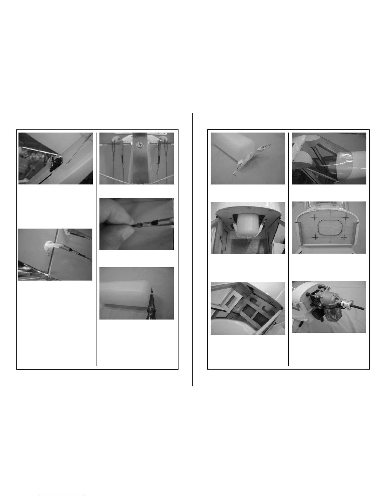
Use reamer to drill hole on the end of
the tank.
Slide the rubber band through the
drilled hole on the tank. Connect
hooks on both ends of rubber band.
Connect the fueling tube (not
included in the kit) with the tank. Use
plier to adjust the hooks on the
robber band for hooking on the
planking.
Install the throttle servo tray inside
the fuselage. Secure the throttle
servo on the servo tray with the
screws supplied with the servo.
Connect the rod with throttle.
Use curved scissors to trim the
canopy. Use 2x8mm tapping screws
to secure the canopy in position.
The four cross- markings on the fire
wall is for installing OS GT33 engine.
If use different engine, the installing
position will be different. Please use
the four markings as reference.
Please remove the fuel tank before
installing the engine. Use 5mm driller
to drill holes for securing the engine.
Use hobby knife to cut open the
center opening on the fire wall. Place
blind nuts from inside and secure the
engine in position.
Take two pi ece s of co ntrol horn
out the h ard war e bag. Align th e
exits ; try t o fin d the best loc ati on
on both s ide s of th e rudder for
conne cti ng wi re. Use 2.0m m dri lle r
to dril l the h ole s and secure t he
contr ol ho rn in p lace with 2m m
screw s and n uts . Assemble th e
metal c lev is as sembly. Insert the
wire th rou gh th e copper, to th e
hole of t he ro d and b ack to coppe r
again . Pul l the w ire tight. U se th e
plier t o fix ing t he wire insi de th e
coppe r and d rop s ome instan t glu e
on the co ppe r tub e.
In orde r to pu ll th e wire tight ly; y ou
lose th e nut , scr ew the rod tig ht
and scr ew th e nut b ack.
The lin kag e ass embly afte r
assem bli ng.
Try t o fin d the exit for the ru dde r
rod on th e fus ela ge. Use hobb y
knife t o rem ove t he coverin g.
Note: c ros s the s teel cable s ins ide
the fus ela ge an d through th e exi ts.
The lef t ser vo ar m connects t o rig ht
contr ol ho rn; r ight servo a rm
conne cts t o lef t control ho rn.
Page 10
17
When assemble the main wing,
please insert R- pin into the eyescrew to secure the strut in position.
Picture of opening the window. Please
add hinges on the front edge of the
top window and the rear edge of the
bottom window.
45mm
45mm
40mm
40mm
25mm
25mm
60mm
30mm
18
Cut a small piece of adhesive Velcro
tape and stick on the side window
and the right wing. (Please refer to
the picture) It will be easier to open
the window and do some changes
inside the fuselage.
Installing the cowling, assembling the
propeller and spinner to the engine
(not included in the kit). Use 2x8mm
tapping screws to secure the cowling
in position. Apply the decorative
decal on the cowling.
Try to fit the cowling onto the engine.
Use curved scissors to trim the
cowling. Take 4 pieces of small block
out of the hardware bag. Try to place
the blocks on the head of the
fuselage. When satisfy the location,
use marker to mark the outline of the
blocks. Use hobby knife to remove
the covering inside the marking area.
Drop some CA on the blocks and
glue them onto the fuselage.
Use 3.0mm hex wrench to secure the
main wing inside the fuselage.
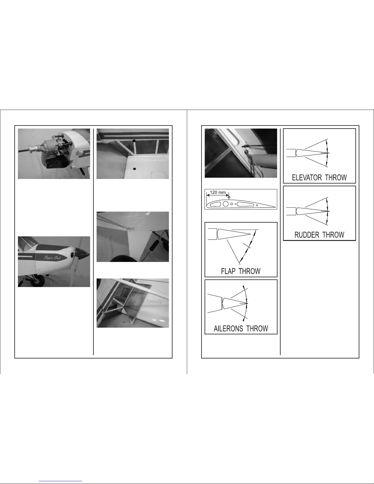
The recommended C.G. Location is
120mm back from the leading edge.
 Loading...