

SuperDroid Robots IG52-DB Assembly And Operation Manual
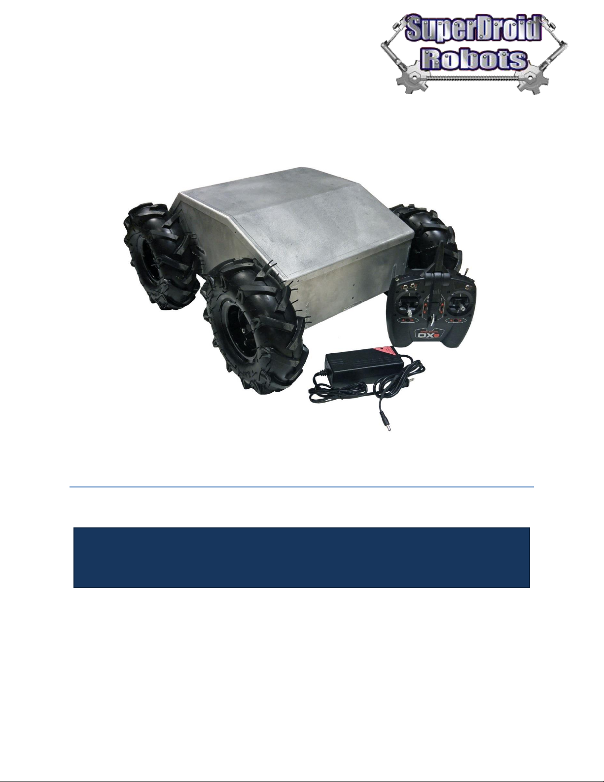
IG52-DB Heavy Duty Enclosed Robot
Assembly and Operation
The IG52-DB Enclosed is a rugged and powerful robot platform. Make it RC or use it with sensors
and a microcontroller to make it autonomous/semi-autonomous.
Images shown may not be an exact representation of the robot’s features listed in this document

SuperDroid Robots, Inc Contact
224 Technology Park Lane (919) 557-9162
Fuquay Varina, NC 27526 SDR@SDRobots.com
www.SuperDroidRobots.com
Revised: February 8, 2019 Page 2 of 13
Contents
Mechanical Assembly ................................................................................................................................................... 4
Electrical Assembly ..................................................................................................................................................... 10
Operation .................................................................................................................................................................... 12
General Terms............................................................................................................................................................. 13
SuperDroid Robots, Inc Contact
224 Technology Park Lane (919) 557-9162
Fuquay Varina, NC 27526 SDR@SDRobots.com
www.SuperDroidRobots.com
Revised: February 8, 2019 Page 3 of 13
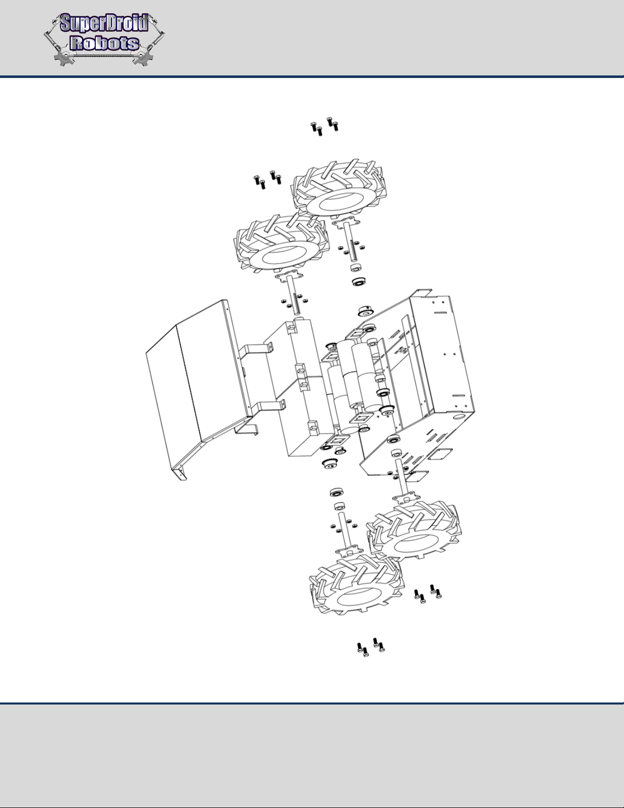
Figure 1: Exploded view sketch
SuperDroid Robots, Inc Contact
224 Technology Park Lane (919) 557-9162
Fuquay Varina, NC 27526 SDR@SDRobots.com
www.SuperDroidRobots.com
Revised: February 8, 2019 Page 4 of 13
Mechanical Assembly
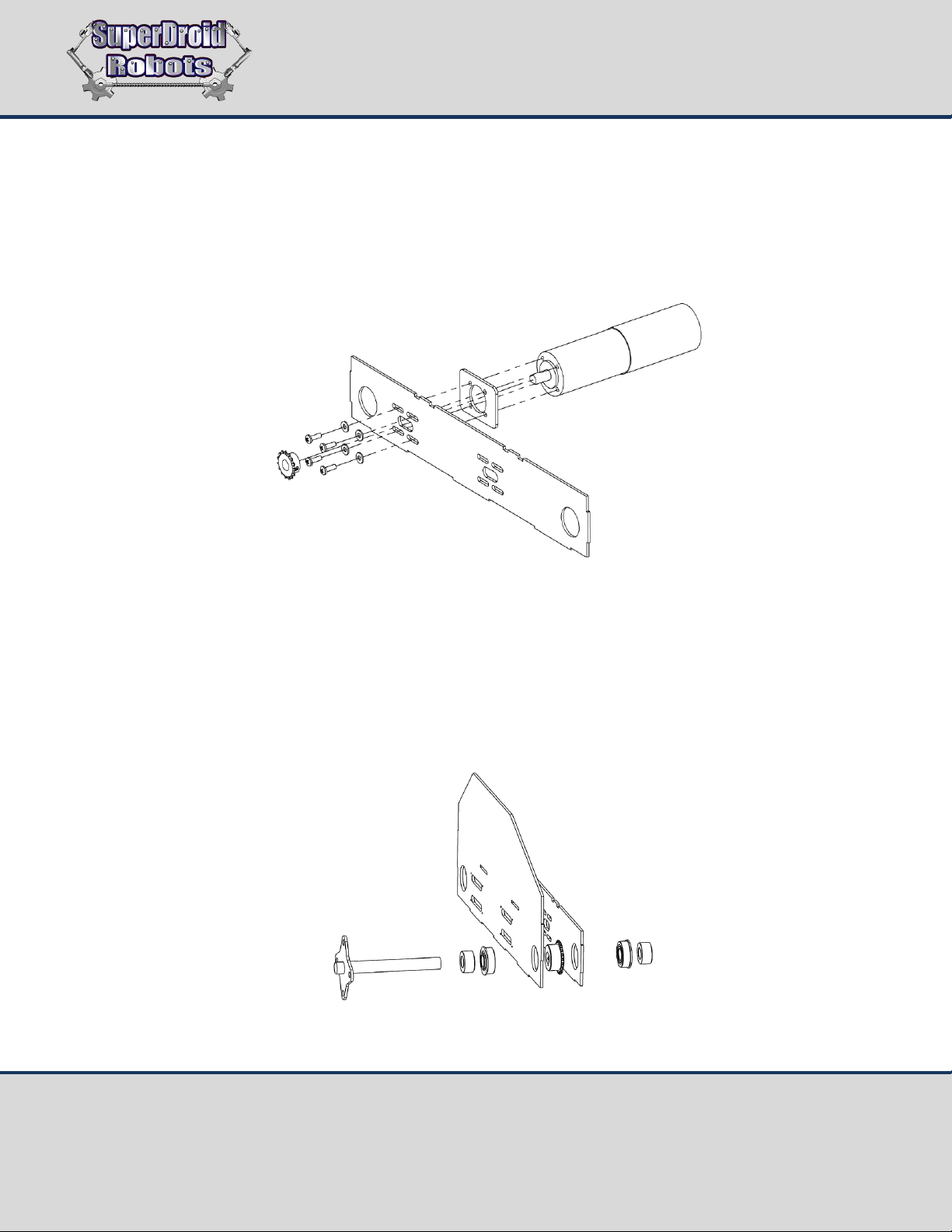
1. Mount the motors as shown in Figure 2, with the motor spacer plate between the motor and the chassis.
Make sure to use Loctite on the screws. Once the motor is mounted, the small sprockets can be mounted
on the motor shaft. The hub should face the motor and they should be pushed all the way against the
inside plate with just a small clearance for rotation.
Figure 2: Exploded view sketch of motor mounting
2. Slide all 8 bearings into place through the bearing holes in the chassis. Slide a lock collar onto the axle,
then slide the axle through the first bearing. At this point, put the key in the shaft and slide on the wheel
sprocket. Finally slide the shaft through the second bearing. Slide another lock collar on to secure the
inside bearing and slide the outside lock collar over to secure the outside bearing. Use Loctite on all set
screws.
Figure 3: Axle assembly
 Loading...