

Page 1
1 WIP58xxN -WR_PQ
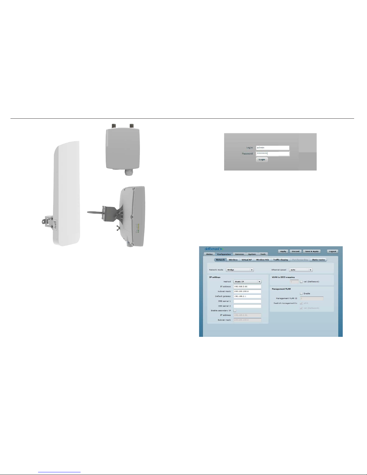
3. Open a web browser to the d efault IP address of the AP device ht tps://192.168.2.66/. The login page will appear. :
Figure 1 – Login page
4.
Enter the default pa ssword, then press the Login b utton to enter the AP web management page. T he default administrator login
settings are:
Login: admin
Password: admin 01
After a successf ul administrator login you will se e the main page of the device Web management inter face. The device now is ready
for conguration se tup.
5. Navigate to the Congur ation | Network tab and cho ose the Bridge networ k mode. Keep the IP method set to Static IP an d enter
the desired net work address setting s for the Access Point.
Figure 2 - Conguration | Network page
For product s: WIP5800N-WR, WIP5818N-WR, WIP5890N-WR
WIP5800N -WR
WIP5890N-W R
WIP5818N-WR
Step 1. Power on a WIP58 xxN-WR D evice
All WIP products o perate on a proprietary PoE vo ltage using the PoE injector provi ded. The injector has two R J-45 Ethernet por ts for
connections. T he PoE port is used to connec t power to the WIP device. The LAN por t is used to connect the WIP di rectly to an IP camera or
network sw itch.
1. Connect the 110 Vac power cord to the PoE Injec tor.
2. Connect a CAT5 cable to the PoE po rt on the injector and the R J-45 port on the WIP dev ice.
3. Connect a CAT5 cable to the L AN port on the PoE injector an d the RJ-45 port on an IP c amera or network switch (if mul tiple IP
cameras will be use d on a single WIP wireless device).
Step 2. Set up the Initia l Access Point
The default WIP58x xN-WR product address is 192.168.2.66.
1. To access the Web management interface, con gure your PC with a static IP addres s on the 192.168.2.0 subnet. Use the subnet mask
255.255.255.0.
2. Connect the AP dev ice in to the same physical networ k as your PC.
WIP58xxN-WR Quick Start Programming Instructions
Page 2
2
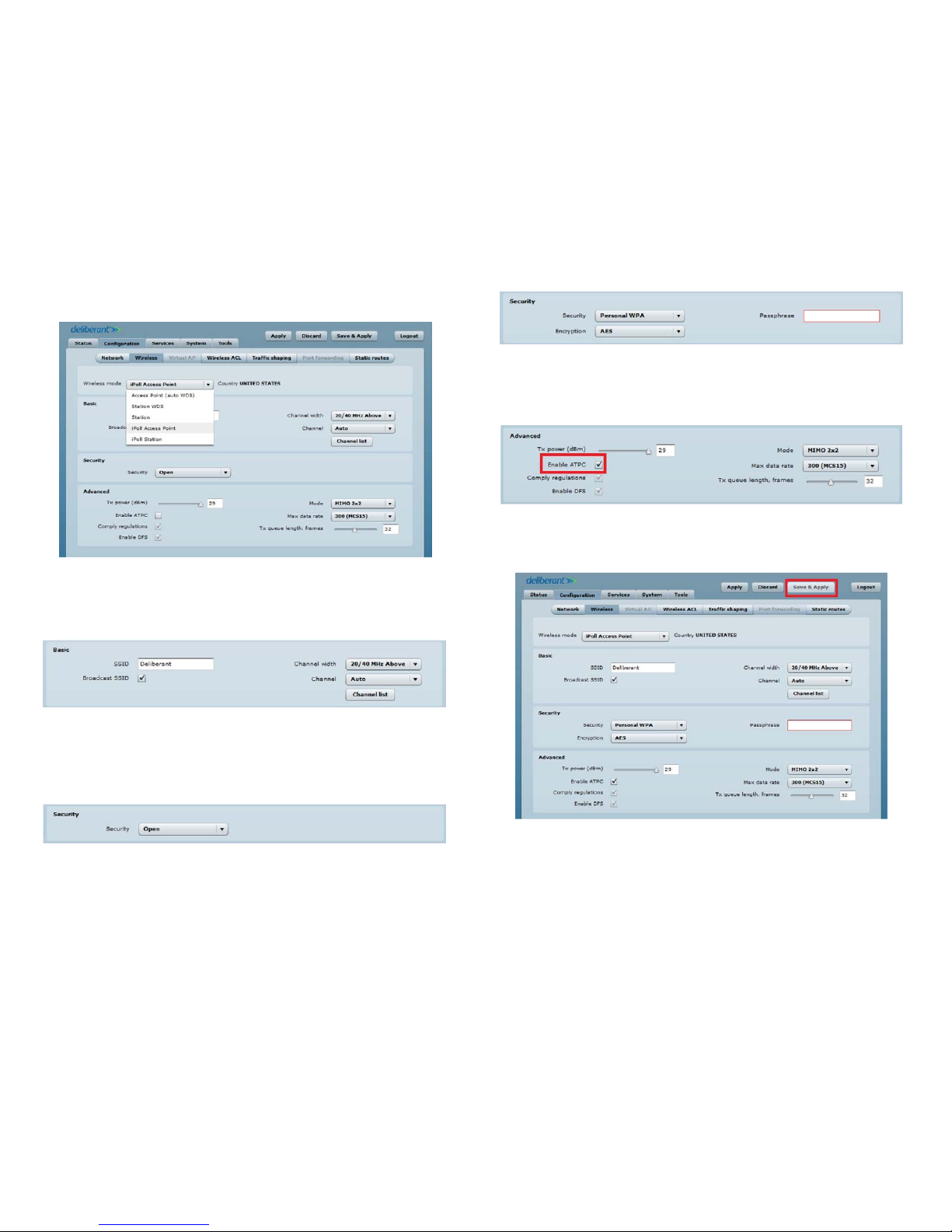
Figure 6 – Security setup for WPA/WPA2
9.
To ensure the transmission power of t he wireless device is set for any environ ment, check on the Enable ATPC box. This w ill
automatically adjust t he TX power of the device. Leave all other set tings at the defaults shown.
Figure 7 – Advanced setup
10.
Click Save & Apply at the to p right of the screen.
Figure 8 – Save setup
If you changed from t he default IP address of the unit, yo u will lose your connection to the de vice. To reconnect to the Access Point,
enter the new IP address of t he Access Point into the address (URL) eld of the brow ser.
6. Navigate to the Congur ation | Wireless tab, then se lect iPoll Access Point f rom the rst drop down menu.
Figure 3 – Wireless mode setup
7.
Create the SSID for the wirele ss network. The defau lt SSID, Deliberant, can be changed to any desired SSID nam e. Ensure the check box
is marked to Broadc ast SSID. Leave the Channel width and Cha nnel settings at the def aults shown below.
Figure 4 – Basic wireless setup
Channel Width and Channel s election can be changed i f necessary to avoid interf erence in your installation environment.
8. Set the desired S ecurity for the wirele ss network. The def ault setting is Open.
Figure 5 – Security setup default
Options for Perso nal WPA and Personal WPA2 are available with AES encry ption. If you selected one of th ese, create a Passphrase. The
Passphrase must b e 8 characters long.
Page 3
3
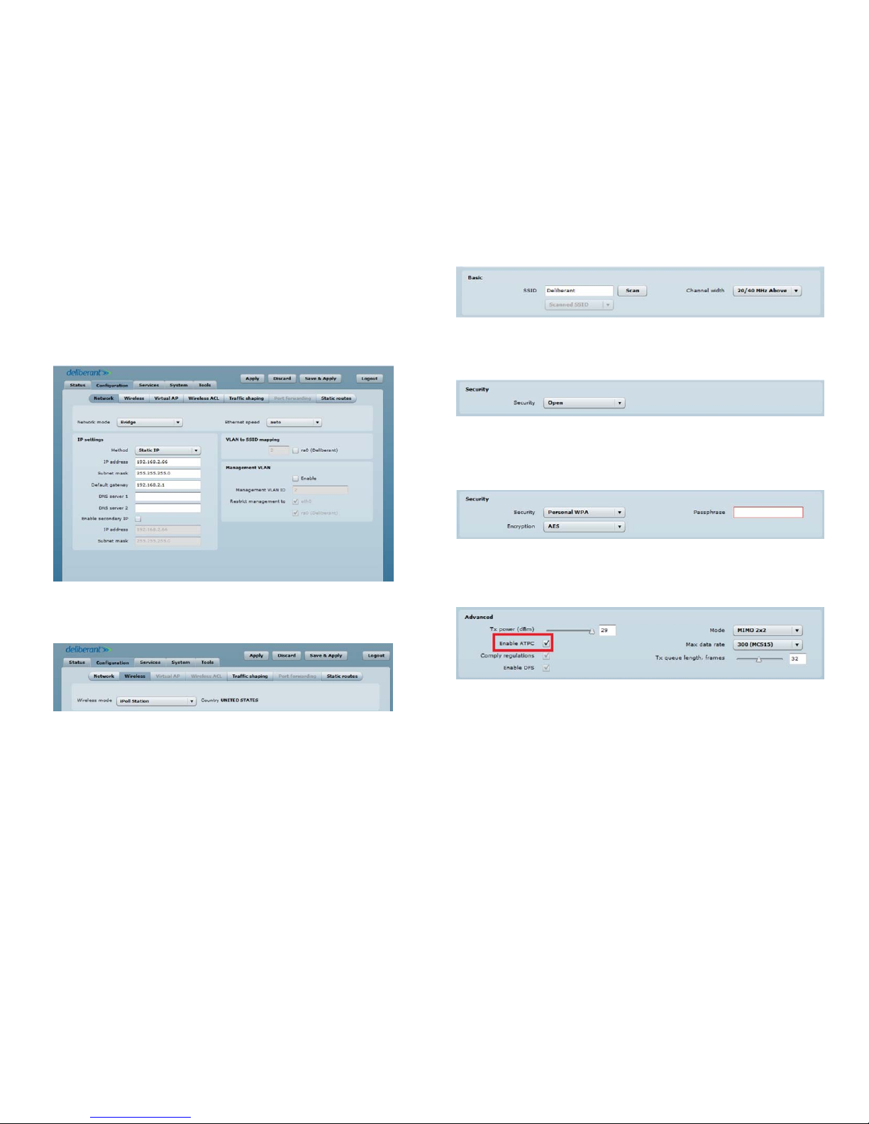
Figure 11 – Wireless mode setup
5.
Match the Secur ity settings of the Access Poin t you will connecting to. The default s etting is Open.
Figure 12 – Security setup default
Options for Perso nal WPA and Personal WPA2 are available with AES encry ption. If you selected one of th ese, enter the matching
Passphrase.
Figure 13 – Security setup WPA/WPA2
6.
To ensure the transmission power of t he wireless device is set correc tly for any environment, check t he Enable ATPC box. This will
automatically adjust t he TX power of the device. Leave all other set tings at the defaults shown b elow.
Figure 14 – Advanced setup
7.
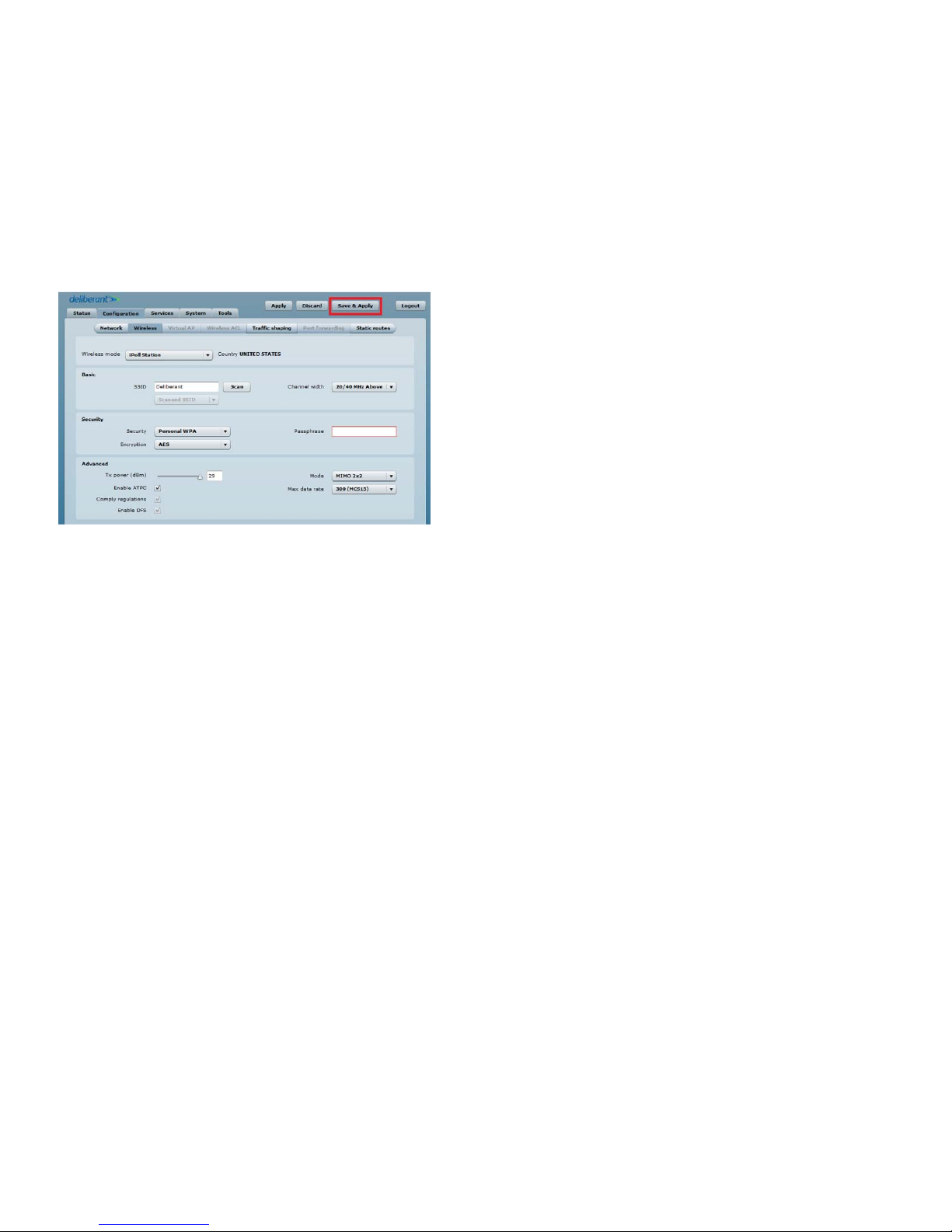
Click Save & Apply at the to p right of the screen.
Step 3. Set up the Initia l Stati on
1.
Repeat 1 – 3 from Step 2 above to lo g into the wireless device.
2. Navigate to the Congur ation | Network tab, then cho ose the Bridge networ k mode. Keep the IP method set to Static IP, and enter
the desired net work address setting s for the Client Station. The IP address mu st be on the same subnet as the Access Poin t it will be
connecting to on th e wireless network. For e xample, if the Access Point is set to 192.168.2.66, set the Station to 192.168.2.67.
Figure 9 – Network setup
3.
Navigate to the Congur ation | Wireless tab, then cho ose iPoll Station from th e Wireless mode drop down me nu.
Figure 10 – Wireless mode setting
4.
If the Access Point is online, you can sc an for the SSID of the wireless net work by pointing the antenna of the stat ion toward the Access
Point. If the Access Point in not online, manua lly enter in the SSID of the Access Point that the Station will be con necting to when
deployed. Ensure the Ch annel width setti ng matches the setting of the Acces s Point you are connecting to.
Page 4
4 © 2012 Observint Technolog ies, Inc. All rights res erved.
Figure 15 – Save setup
If you changed from t he default IP address of the unit, yo u will lose connection to the dev ice. To reconnect to the Station, enter the
new IP address of the Stati on into the address (URL) eld Se tup of the browser.
Step 4. Set up Point to Multipoint (P TMP)
If you have a PTMP deployment, rep eat Step 3 above for all Stations that will connec t to the same Access Point. Each stat ion must have a
static IP address o n the same subnet as the Access Point, and all SSID and se curity setting s must match the Access Point settin gs.
 Loading...