

Page 1

Indoor Monitor
OPERATION INSTRUCTION
4-Wire Villa Video Intercom System
User Manual
Page 2
LIMITATION OF LIABILITY
This users' manual is supplied 'as is', with no warranties, be it expressed or implied, including,
but not limited to, the implied warranties of merchantability, suitability for any exact purpose, or
non-infringement of any third party's rights.
This publication may include technical inaccuracies or typos. The manufacturer holds the right
to introduce any changes to the information contained herein, for any purpose, including but not
limited to, improvements of the publications and/or related to the product, at any time, without
prior notice.
DISCLAIMER OF WARRANTY
The supplier shall not be liable to any party or any person, except for replacement or reasonable
maintenance of this product, for the cases, included but not limited to the following:
Any damage or loss, including but not limited to: direct/indirect, consequential, special, exemplary,
arising out of or related to the product;
Inappropriate use or negligence of the user in operation of the product, resulting in personal injury
or any damage;
Unauthorized disassembly, repair or modification of the product by the user;
Any problems or consequential inconvenience, loss or damage, caused by connecting this product
to devices of the third parties;
Any claim or action for damages, brought by any photogenic subject, be it a person or organization,
due to violation of privacy whereby the pictures taken by the device and/or saved data become
public or are used for the purposes other than intended.
SAFETY INSTRUCTIONS
1 2
Read these instructions and keep them in a safe place for future reference.
Please refer all work related to the installation of this product to qualified service personnel or
system technician.
Do not operate the appliance beyond its specified temperature, humidity or power source ratings.
Securely install the devices on vertical surfaces (solid walls/doors) not prone to vibration or impact.
oooo
Use the appliance at temperatures between 10 C ~ +60 C (14F ~140 F) without excessive
exposure to the extreme values indicated.
Install the devices away from heat sources such as radiators, heat registers and stoves.
Installation of the terminal near consumer electronics devices, e.g. stereo receiver/amplifiers and
televisions, is permitted as long as the air surrounding the terminal does not exceed the above
mentioned temperature range.
Handle the appliance with care. Do not strike or shake, as this may damage the device.
The doorbell/camera units should be fitted with an approved weather shield if the chosen position
is in direct sunlight, or in contact with rain, snow or irrigation sprinkler systems.
Do not use strong or abrasive detergents when cleaning the appliance body. When the dirt is
hard to remove, use a mild detergent and wipe gently.
Do not overload outlets and extension cords as this may result in a risk of fire or electric shock.
Distributing, copying, disassembling, reverse compiling, reverse engineering, and also exporting
in violation of export laws of the software provided with this product, is expressly prohibited.
CARING FOR THE ENVIRONMENT BY RECYCLING
When you see this symbol on a product, do not dispose of the product with residential
or commercial waste.
Recycling your electrical equipment
Please do not dispose of this product with your residential or commercial waste. Some countries or
regions, such as the European Union, have set up systems to collect and recycle electrical and electronic
waste items. Contact your local authorities for information about practices established for you r region.
COPYRIGHT STATEMENT
All rights reserved. No part of this publication may be reproduced in any form or by any means,
transcribed, translated into any language or computer language, transformed in any other way,
stored in a retrieval system, or transmitted in any form or by any means, electronic, mechanical,
recording, photocopying or otherwise, without the prior written permission of the owner.
Page 3
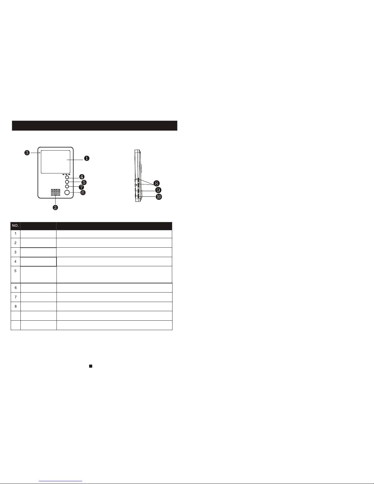
INDOOR MONITOR
3
Monitoring
Speaker
TFT display
View visitor images displayed on the TFT screen
Microphone
Sound from outdoor camera
Call transfer
/Surveillance
Transfer call to other extension monitor or watch the outside image
from the standby mode.
Talk
Transmit the voice to outdoor camera
Unlock
Unlock the door lock by pressing this button
Adjust the chroma, contrast and luminace of TFT display
Talk Volume
Adjust the speaker volume
Ring volume
Adjust the ring volume
Allow you to observe the image of camera view at entrance in
real time.
Start conversation with outdoor visitor via camera
Chroma /Contrast
/Luminance
Name
Descriptions
9
10
Page 4
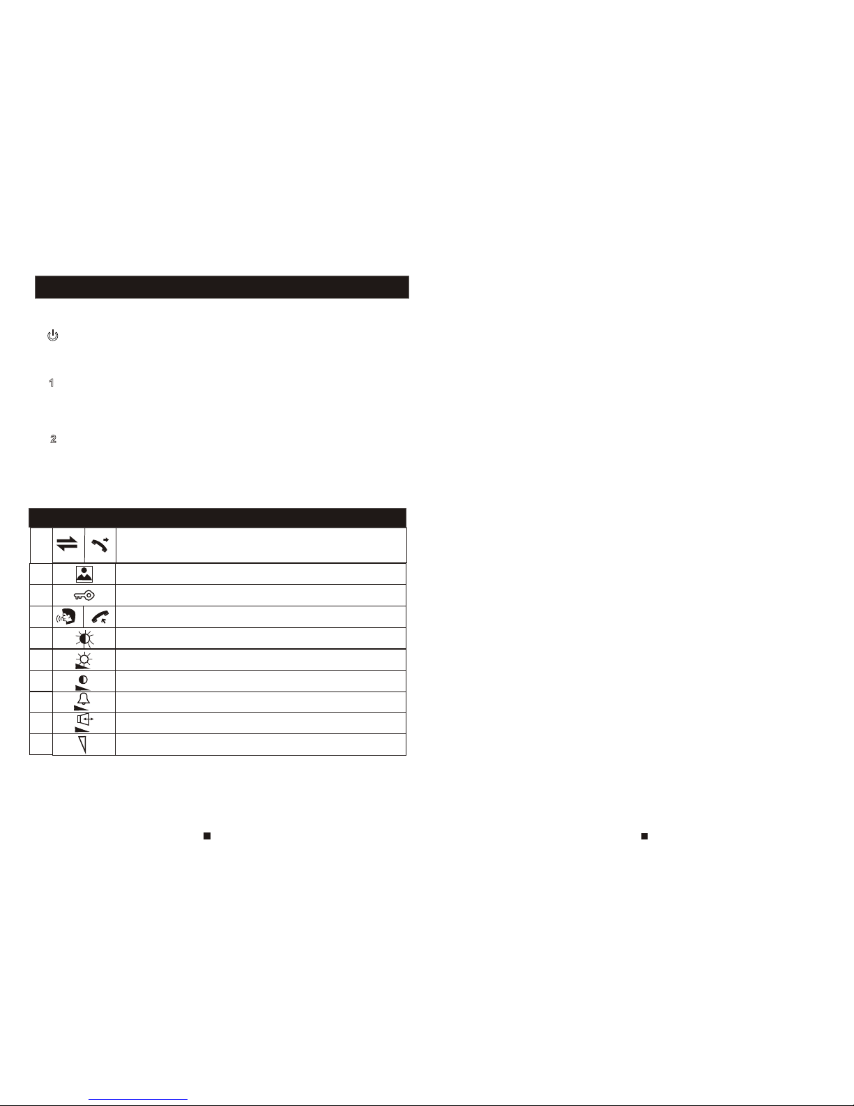
Call transfer to other indoor monitor. Watch the outside image from the
external camera under the standby model
Observe the image of camera view at entrance in real time
Release the door lock
Activate conversation mode by pressing this button
DESCRIPTION ON SYMBOL
DESCRIPTION ON LED INDICATOR
Adjust the chroma contrast and luminace of the TFT display
Increase/decrease the ring volume
When lit, this LED indicates this indoor unit is connected to
main power supply.
When lit, this LED indicates that this indoor unit is communicating with the
1st outdoor camera.
The front panel includes three LED indicators:
LED 3
LED 1
LED 2
When lit, this LED indicates that this indoor unit is communicating
with the 2nd outdoor camera.
Increase/decrease the talk volume
Adjust the speaker volume
Adjust the brightness of the TFT display
Adjust the chroma of the TFT display
5
6
Page 5
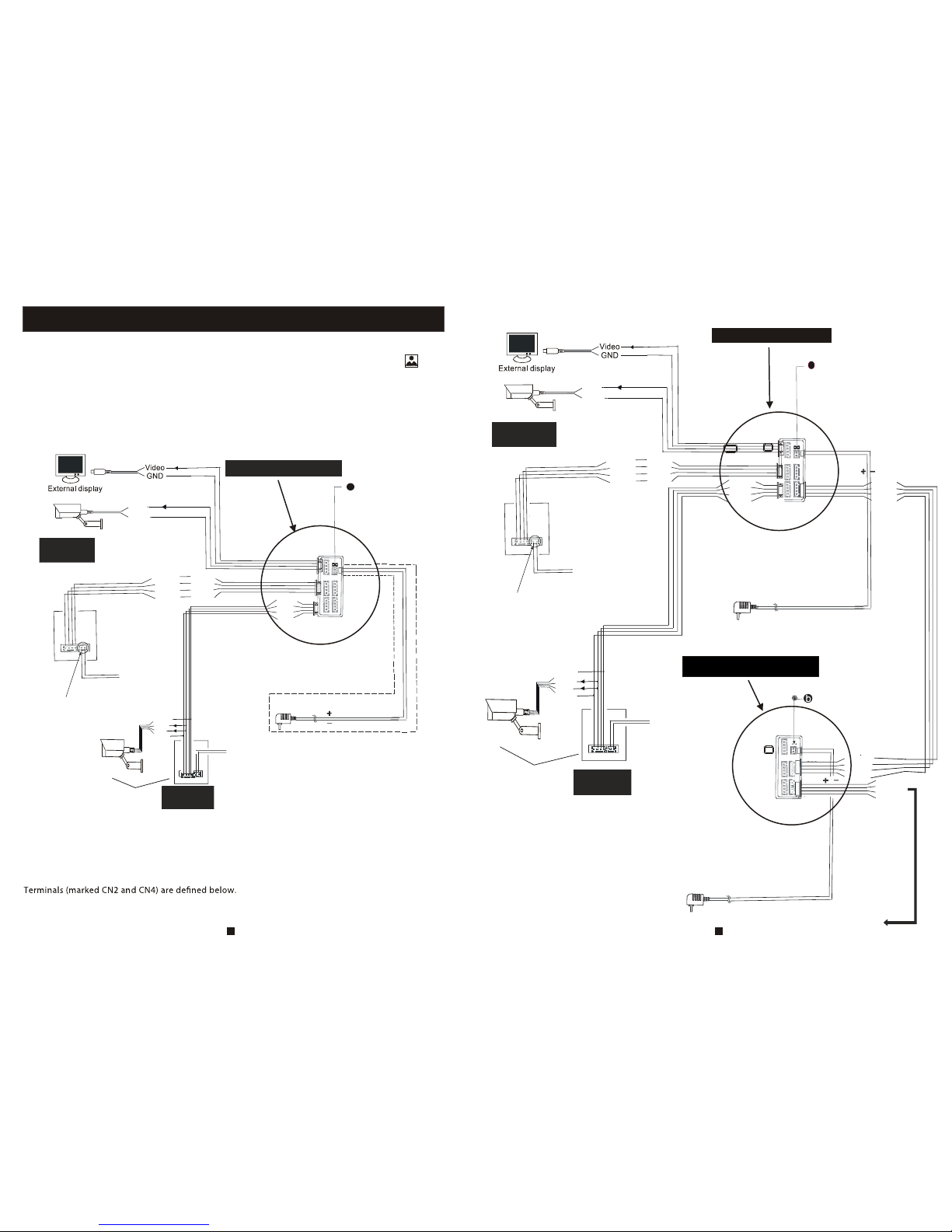
WIRING DIAGRAM
If you are using only one outdoor camera, you must connect it to the socket marked CN1. If the
only outdoor camera is connected to the CN2 socket, the indoor unit will display a blank screen
when you attempt to activate monitoring mode to 1st outdoor camera by pressing the button .
Please note that the part marked by the broken line is not present if you are using the indoor
unit, which has an internal switching power supply. Therefore you can connect the AC plug
directly to the AC power supply.
The functionality of terminals C N1 and CN2 is shown below:
1.Red:DC12V 2.Yellow: Audio 3.Black: GND 4.White:Video
If you are using two outdoor cameras (for example, at the front door and the back gate), you must
use the CN1 CN2 . The two wires for connecting to the outdoor units are s
hown in
the picture below.
and sockets
Up to 4 indoor monitors can be connected with 2 outdoor
cameras.
A. Red: Audio B. Yellow: GND C. Black: Data D. White: Video
J
C
N
1
C
N
2
C
N
3
C
N
4
1.
R
e
d
2
.Y
e
l
.
3
.B
l
k
.
4
.
W
h
.
D
C
1
2
V
A
u
d
i
o
G
N
D
V
i
d
e
o
D
r
y
c
o
n
t
a
c
t
4
3
2
1
AC100V~240V
External switching power supply
aa
a
a
a
2P short pin plugged in
Video
GND
External camera
CN5
3
OUTDOOR
CAMERA 1
J
C
N
1
C
N
2
C
N
3
C
N
4
1.
R
e
d
2
.Y
e
l
.
3
.B
l
k
.
4
.
W
h
.
D
C
1
2
V
A
u
d
i
o
G
N
D
V
i
d
e
o
D
r
y
c
o
n
t
a
c
t
4
3
2
1
AC100V~240V
External switching power supply
a
a
a
2P short pin plugged in
Video
GND
External camera
CN5
3
OUTDOOR
CAMERA 2
DC12V
Audio
GND
Video
43 2 1
A.Red
B. Yel.
C. Blk.
D.Wh.
CN3
A.Red
B. Yel.
C. Blk.
J
4
CN
1
(not included)
CN4
D.Wh.
A.Red
B. Yel.
C. Blk.
D.Wh.
C
N
2
External switching power supply
C
N
5
2P short pin pulled
To next extention unit C 3
N
AC100v-240V
GND
Camera
DC12V
Video
Select one
C
N
2
DC12V
Audio
GND
Video
43 21
(not included)
GND
Camera
DC12V
Video
Select one
OUTDOOR
CAMERA 2
GND
GND
7
8
C
N
2
OUTDOOR
CAMERA 1
Page 6
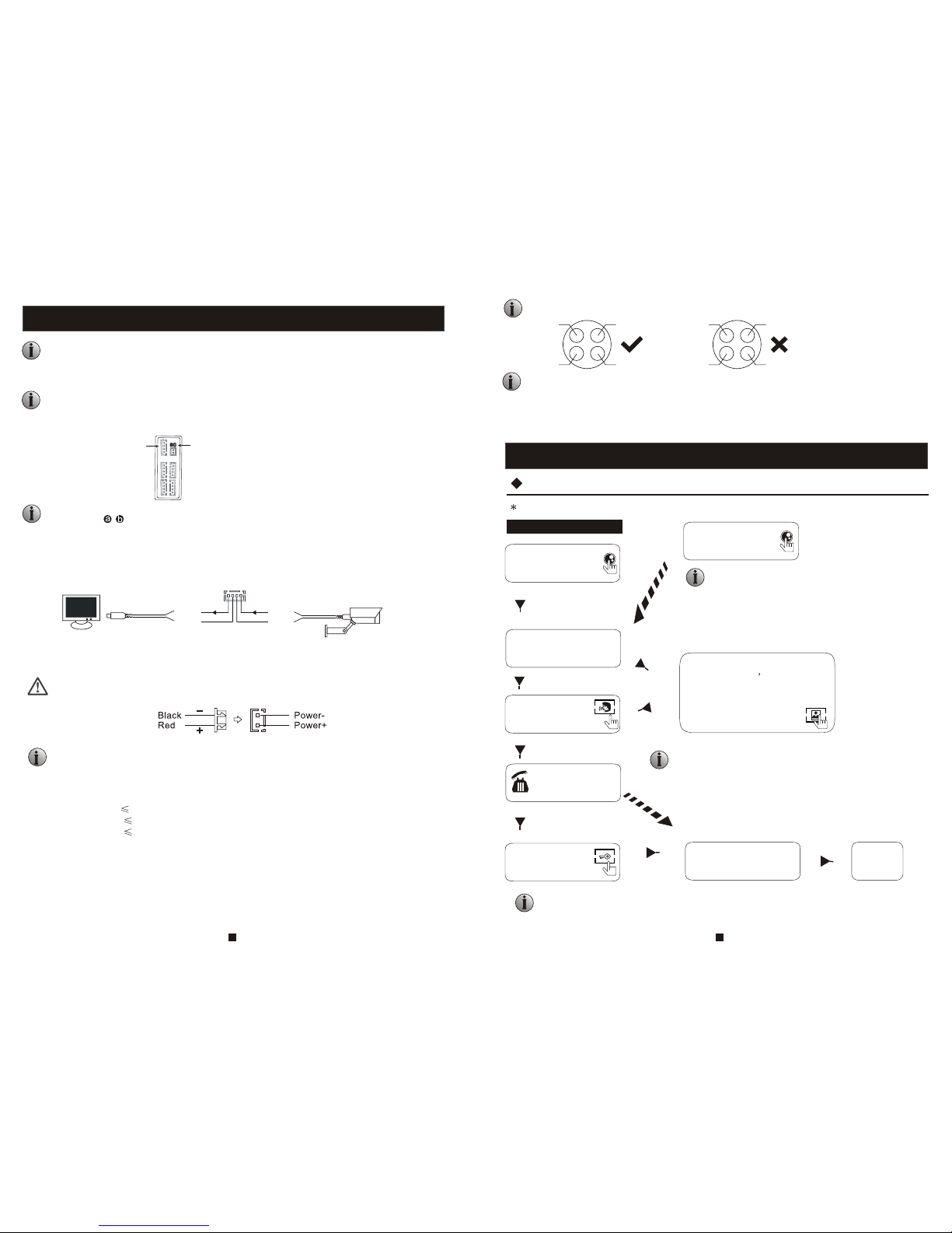
NOTE ON WIRING CONNECTION
OPERATION INTRODUCTION
VISITOR CALL
The Visitor press
the call button on
outdoor camera 1
A 10s of continuous Ding
Dong tone is played
inside and outside
The visitor's
image is
automatically displayed on
the screen
release the
door lock
Standby mode
Press the unlock
button on indoor
monitor
Press the Talk button
on indoor monitor again
End
The Visitor press
the call button on
outdoor camera 2
If the call buttons of two outdoor camera are pressed at the same
time, the preference will be given to the outdoor camera whose
call button was pressed first, unless the call button is pressed
again after the indoor monitor goes into standby mode.
There is no indication on second outdoor camera except that a
brief tone will sound on the indoor monitor.
NOTE:
Both the sound and image from the camera remain on for 20 seconds after the
unlock button is pressed.
Start conversation
with outdoor camera
Press the Talk
button
The indoor unit will automatically go into standby mode if you are
not home or do not reach the indoor unit within 60 seconds.
The conversation
duration is 120s
at a time
Stop ringing
NOTE:
Please be aware of Connection of 2 outdoor cameras is required.
Please follow the terminal markings on PCB to avoid incorrect connections.
The wiring connection requirement :
1. 4C ordinary non-STP wiring cable,
Transmission 90 feet (0.2 mm = 24 AWG)
Wiring connection according to the following to avoid interference
Power+ Video
Audio
GND GND
Audio
Power+ VideoBoth
Both outdoor units must be connected to the main monitor. The socket marked CN1 is for
outdoor camera 1, and CN2 is for outdoor camera 2. Connect other extension monitors in
in serial, one by one. The auxiliary connection of last extension monitor (near the
main monitor) is connected directly to main monitor (the socket marked CN4).
Please note that the 2P Short Pin is designed for programming the indoor monitor (see page 7 and
8 marked as ). The indoor monitor will be programmed to main monitor if you plug in the
2P Short Pin; however the indoor monitor will be programmed to extension monitor if the
2P Short Pin is pulled out.
2. Effective distance from the outdoor camera to furthest indoor monitor:
Transmission 160 feet (0.3 mm = 22 AWG)
Transmission 260 feet (0.4 mm = 20 AWG)
Normally, the the system supports locks with Normally Open (N.O.) door unlocking
method. This means that in the normal state, the dry contacts (page5) are open so the lock
is in a constant closed state.
Please verify that connections of the external power source to the power supply are correct
before applying power to the system. If connected incorrectly, severe damage can occur.
In addition, the system also supports connection to one external camera. Y
ou can also connect it
to one external display. For connection details (socket CN5), see the diagram below:
Video
GND
CN5
External display
Video
GND
External camera
CN5
J
3
Please note that the camera connected to CN2 is used to watch the image around the door if
the camera of outdoor unit is masked. CN2 can be only connected one device, so you can
select either outdoor unit 2 or the camera.
Note that the electric current to camera is 300 mA max.
If the camera in outdoor unit is
masked, and can't see the image.
Press this button to watch the image
from camera. Press it again to back
to the image of outdoor
unit.
9
10
Page 7
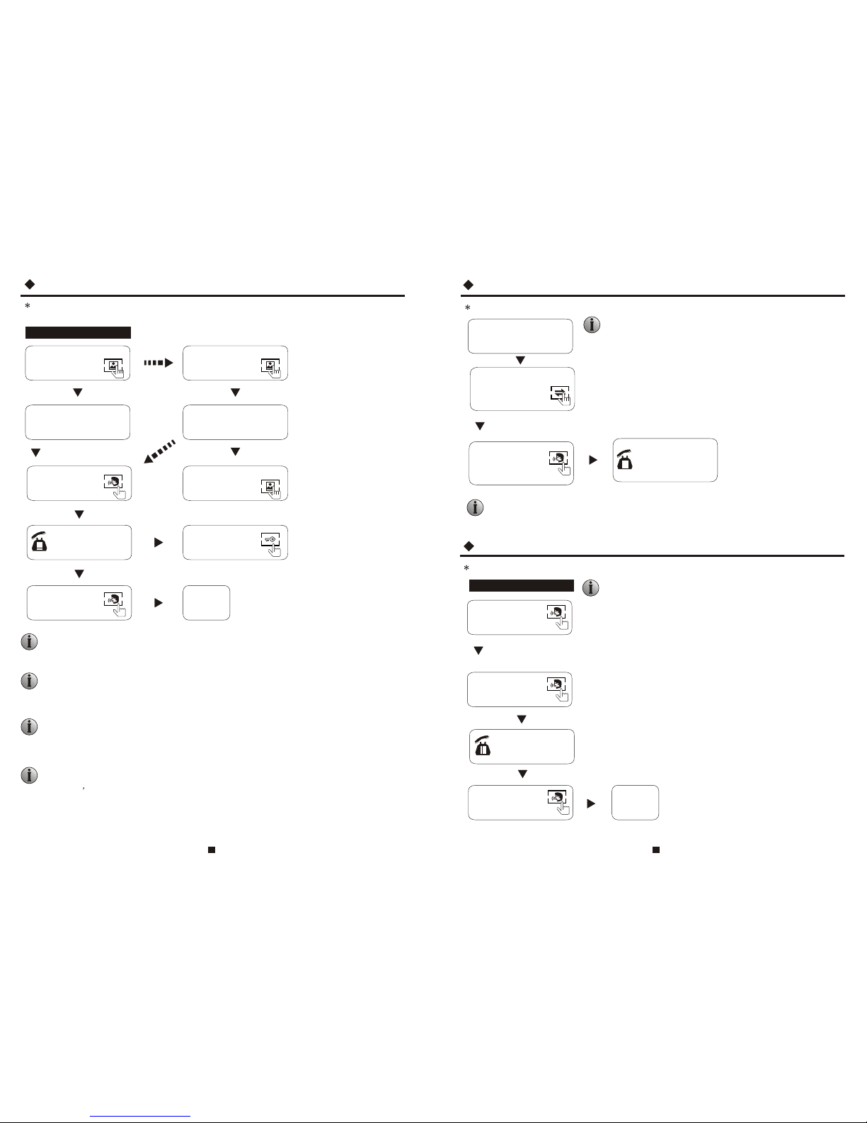
If a conversation with outdoor unit is underway in monitoring mode, during this time a visitor
press the call button on either of outdoor unit, the monitoring mode will be switched off. the
just visitor s image will appear on its screen and continuous ringing will be heard. you can
press the Talk button to reactivate conversation with the visitor ;for more detailed operations,
please refer to VISITOR CALL on page 8.
MONITORING
Press the monitoring
button on indoor
monitor
Standby mode
Press the Talk
button
End
Press the monitoring
button on indoor
monitor again
display image from 2nd
outdoor camera on the
screen.
Press the Talk
button again
monitoring duration
is up to 60 seconds
Press the unlock
button to release
the door lock
If you are using two outdoor cameras, but a blank display appears when
you activate monitoring mode on either indoor unit, disconnect
all power supply to the indoor unit, wait 10 seconds, then reapply
power.
Display image from 1st
outdoor camera on the
screen.
Start conversation
with outdoor camera
CALL TRANSFER TO ANOTHER EXTENSION
Press this button to access
Call transfer to
other extension
Start conversation
with outdoor camera
If you are using two indoor units, activate monitoring mode on both indoor
unit to see the same image on both screens. The image displayed depends on
which outdoor unit is being activated from the indoor unit, or which monitoring
button was pressed last.
When you are transferring a call to other extension, the original
conversation indoor unit will return to standby mode, and the
indoor unit which the call is being transferred will also sound a
continuous Ding Dong tone and the video image will appear on
its screen.
A continuous Ding
Dong tone is sounded
To release the door lock and end the conversation, please refer to page 8.
NOTICE:
Press the Talk
button on any of
indoor units
Outdoor camera call indoor
monitor and conversation
is underway
NOTE:
Press this button once
more to return to
standby mode
NOTE:
If you are using only one outdoor camera in monitoring mode, you can also end the
monitoring mode by pressing the monitoring button again. T
The connection of 2 outdoor cameras to 1 indoor monitor is required for dual entrance
monitoring.
INTERNAL COMMUNICATION BETWEEN INDOOR UNITS
Press the Talk
button on any of
indoor units
Start conversation
among indoor units
Standby mode
Press the Talk
button
A continuous Ding
Dong tone is heard
Press the Talk
button again
End
NOTE:
In internal communication mode, if a visitor presses the call
button on either outdoor unit, the internal communication
mode will be switched off. The visitor's image will appear
on its screen and continuous ringing will be played. You can
press the Talk button to reactivate a conversation with the
visitor. For more detailed operations, please refer to VISITOR
CALL on page 8.
At least 2 indoor units are required
At least 2 indoor units are required
11
12
Page 8
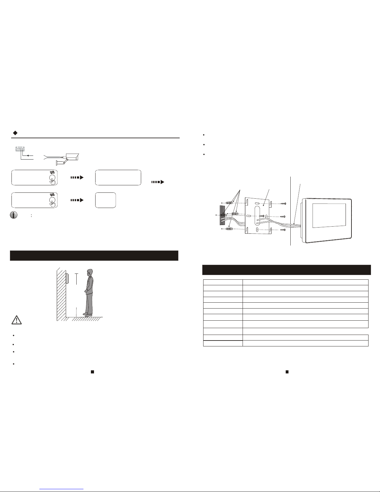
SPECIFICATIONS
Display
Resolution
4 inch TFT LCD
320 (RGB) x 234
Conversation duration
Standby status
Power supply
Operation temp.
Installation
Intercom mode
Working status
Surface mount
400mA max
120 seconds
NOTE:
Do not install the device near strong radiation sources, such as a TV set, video recorder, PC etc.
Avoid shaking, beating o n, or coliding with the device. Oherwise , internal components maybe
damaged.
Do not apply power to the device until after it is completely installed.
Position the AC power supply at least 12 inches away from the unit to avoid interference.
INSTALLATION OF INDOOR UNITS Place the moni
Keep the unit away from the water and magnetic eld.
Maintenance should be performed by a qualied technician.
Install the monitor in the most suitable location, and at eye level.
Plastic anchors Bracket
Connection
cable
150-160cm
To install the indoor unit, please follow the diagram below:
Video system
PAL/NTSC compatible
CN5
Video
GND
External camera
Press the button to
activate the function
End
Real time
surveillance
Requirements:
1. Connect the external camera
2. In the standby mode
Display the outside image
Press the button
again to switch o
Note In monitoring mode, if a visitor press es the call button on either
outdoor unit, the internal communication mode will be swithed o. Just the
image will appear on the screen and a continuous
ringing will be played.
You can press the Talk button to reactivate conversation
with the visitor.
For more detailed oprations, please see VISITOR CALL on page 8.
Surveillance
MODE
50mA max.
Duplex communicationSemi-
DC12V/1A
14 ~ 140 °F (-10 ~ +60 °C)
13
14
6.7 x 4.7 x .78 inches
Dimensions
 Loading...