

Super Circuits SYRF204B, SYRF204BLCD, SYRF204BHR Installation And Setup Manual

4-Camera H.264 Security System
Installation and Setup Guide
Products: SYRF204B, SYRF204BLCD, SYRF204BHR
SYRF204BLCD System
PLEASE READ THIS MANUAL BEFORE USING YOUR SYSTEM, and always follow the
instructions for safety and proper use. Save this manual for future reference.
SYRF204B_SI
ii
www.supercircuits.com
CAUTION
Operate this device only in environments where the temperature or humidity is within the recommended range. Operation
at extreme temperatures or in very high or low humidity levels may cause electric shock and shorten the life of the
product.
CAUTION
Installation and servicing should be performed by qualied and experienced personnel only. DVR should always remain
OFF during any installation process.
CAUTION
Do not use the camera if fumes, smoke or a strange odor is emitted from the unit, or if it seems to function incorrectly.
Disconnect the power source immediately, and consult your dealer.
LEGAL NOTICE
Supercircuits products are designed to meet safety and performance standards with the use of specic
Supercircuits authorized accessories. Supercircuits disclaims liability associated with the use of non-Supercircuits
authorized accessories.
The recording, transmission, or broadcast of any person’s voice without their consent or a court order is strictly
prohibited by law.
Supercircuits makes no representations concerning the legality of certain product applications such as the
making, transmission, or recording of video and/or audio signals of others without their knowledge and/or
consent. We encourage you to check and comply with all applicable local, state, and federal laws and regulations
before engaging in any form of surveillance or any transmission of radio frequencies.
Microsof t, Windows, and Internet Explorer are either registered trademarks or trademarks of Microsoft Corporation in
the United States and/or other countries. Android is a trademark of Google Inc. Use of this trademark is subject to
Google Permissions. Apple, iPhone, iPod touch, and iPad are registered trademarks of Apple Inc.
Other trademarks and trade names may be used in this document to refer to either the entities claiming the marks
and names or their products. Supercircuits, Inc. disclaims any proprietary interest in trademarks and trade names
other than its own.
No part of this document may be reproduced or distributed in any form or by any means without the express written
permission of Supercircuits, Inc.
© 2011 Supercircuits, Inc. All rights reserved.
11000 N. Mopac Expressway, Building 300, Austin, TX 78759
Sales/Support: 1.800.335.9777 | Fax: 1.866.267.9777

iii
4-Camera H.264 Security System Setup Guide
Table of Contents
SECTION 1 Systems Overview . . . . . . . . . . . . . . . . . . . . . . . . . . . . . . . . . . . . . . . . . . . . . . . . . . . . . . . . . . . . . . . . . . . 1
1.1 About this document . . . . . . . . . . . . . . . . . . . . . . . . . . . . . . . . . . . . . . . . . . . . . . . . . . . . . . . . . . . . . . . . .1
SECTION 2 Getting Started: Unpacking the Equipment . . . . . . . . . . . . . . . . . . . . . . . . . . . . . . . . . . . . . . . . . . . . . 2
SECTION 3 Installing Your System . . . . . . . . . . . . . . . . . . . . . . . . . . . . . . . . . . . . . . . . . . . . . . . . . . . . . . . . . . . . . . . 4
3.1.1 Camera placement . . . . . . . . . . . . . . . . . . . . . . . . . . . . . . . . . . . . . . . . . . . . . . . . . . . . . . . . . . . . . . .4
3.1.2 Mounting . . . . . . . . . . . . . . . . . . . . . . . . . . . . . . . . . . . . . . . . . . . . . . . . . . . . . . . . . . . . . . . . . . . . . . 5
3.1 DVR installation . . . . . . . . . . . . . . . . . . . . . . . . . . . . . . . . . . . . . . . . . . . . . . . . . . . . . . . . . . . . . . . . . . . . .6
3.1.1 Placement . . . . . . . . . . . . . . . . . . . . . . . . . . . . . . . . . . . . . . . . . . . . . . . . . . . . . . . . . . . . . . . . . . . . . .6
3.1.2 Controls and connectors . . . . . . . . . . . . . . . . . . . . . . . . . . . . . . . . . . . . . . . . . . . . . . . . . . . . . . . . . . 7
3.2 Install and setup a monitor . . . . . . . . . . . . . . . . . . . . . . . . . . . . . . . . . . . . . . . . . . . . . . . . . . . . . . . . . . . .8
3.3 Connecting the system together. . . . . . . . . . . . . . . . . . . . . . . . . . . . . . . . . . . . . . . . . . . . . . . . . . . . . . . .9
3.4 Adjusting the camera . . . . . . . . . . . . . . . . . . . . . . . . . . . . . . . . . . . . . . . . . . . . . . . . . . . . . . . . . . . . . . . .11
3.5 Using the remote control and mouse . . . . . . . . . . . . . . . . . . . . . . . . . . . . . . . . . . . . . . . . . . . . . . . . . . .11
SECTION 4 DVR Setup . . . . . . . . . . . . . . . . . . . . . . . . . . . . . . . . . . . . . . . . . . . . . . . . . . . . . . . . . . . . . . . . . . . . . . . . 13
4.1 Login to the DVR . . . . . . . . . . . . . . . . . . . . . . . . . . . . . . . . . . . . . . . . . . . . . . . . . . . . . . . . . . . . . . . . . . .13
4.2 Conguring the system . . . . . . . . . . . . . . . . . . . . . . . . . . . . . . . . . . . . . . . . . . . . . . . . . . . . . . . . . . . . . .14
4.2.1 Setting the screen language and video system format . . . . . . . . . . . . . . . . . . . . . . . . . . . . . . . .15
4.2.1 Setting the system time . . . . . . . . . . . . . . . . . . . . . . . . . . . . . . . . . . . . . . . . . . . . . . . . . . . . . . . . .15
4.2.2 Change the Admin and user1 passwords . . . . . . . . . . . . . . . . . . . . . . . . . . . . . . . . . . . . . . . . . . .17
4.2.3 Add users to the system . . . . . . . . . . . . . . . . . . . . . . . . . . . . . . . . . . . . . . . . . . . . . . . . . . . . . . . . .18
4.2.4 Set HDD overwrite option . . . . . . . . . . . . . . . . . . . . . . . . . . . . . . . . . . . . . . . . . . . . . . . . . . . . . . . .19
4.3 Record conguration settings . . . . . . . . . . . . . . . . . . . . . . . . . . . . . . . . . . . . . . . . . . . . . . . . . . . . . . . . .20
4.4 Video conguration settings . . . . . . . . . . . . . . . . . . . . . . . . . . . . . . . . . . . . . . . . . . . . . . . . . . . . . . . . . .22
4.4.1 Video setup . . . . . . . . . . . . . . . . . . . . . . . . . . . . . . . . . . . . . . . . . . . . . . . . . . . . . . . . . . . . . . . . . . . .23
4.5 Network conguration settings . . . . . . . . . . . . . . . . . . . . . . . . . . . . . . . . . . . . . . . . . . . . . . . . . . . . . . .25
4.6 Alarm conguration settings . . . . . . . . . . . . . . . . . . . . . . . . . . . . . . . . . . . . . . . . . . . . . . . . . . . . . . . . .25
4.6.1 Motion detection setup . . . . . . . . . . . . . . . . . . . . . . . . . . . . . . . . . . . . . . . . . . . . . . . . . . . . . . . . .27
SECTION 5 Networking Your DVR . . . . . . . . . . . . . . . . . . . . . . . . . . . . . . . . . . . . . . . . . . . . . . . . . . . . . . . . . . . . . . . 30
5.1 Congure the DVR for access on your home network. . . . . . . . . . . . . . . . . . . . . . . . . . . . . . . . . . . . . .31
5.1.1 Verify local network connectability with IE . . . . . . . . . . . . . . . . . . . . . . . . . . . . . . . . . . . . . . . . .36
5.2 Accessing your DVR from the Internet . . . . . . . . . . . . . . . . . . . . . . . . . . . . . . . . . . . . . . . . . . . . . . . . . .40
SECTION 6 Accessing Your DVR With a Web Browser . . . . . . . . . . . . . . . . . . . . . . . . . . . . . . . . . . . . . . . . . . . . . . . 42
6.1 Connecting to your DVR with IE . . . . . . . . . . . . . . . . . . . . . . . . . . . . . . . . . . . . . . . . . . . . . . . . . . . . . . .42

iv
www.supercircuits.com
TABLE OF CONTENTS
6.2 Live screen . . . . . . . . . . . . . . . . . . . . . . . . . . . . . . . . . . . . . . . . . . . . . . . . . . . . . . . . . . . . . . . . . . . . . . . . .43
6.3 Replay window . . . . . . . . . . . . . . . . . . . . . . . . . . . . . . . . . . . . . . . . . . . . . . . . . . . . . . . . . . . . . . . . . . . . .44
6.4 Remote window . . . . . . . . . . . . . . . . . . . . . . . . . . . . . . . . . . . . . . . . . . . . . . . . . . . . . . . . . . . . . . . . . . . .44
6.5 Local setting . . . . . . . . . . . . . . . . . . . . . . . . . . . . . . . . . . . . . . . . . . . . . . . . . . . . . . . . . . . . . . . . . . . . . . .45
6.6 Logout . . . . . . . . . . . . . . . . . . . . . . . . . . . . . . . . . . . . . . . . . . . . . . . . . . . . . . . . . . . . . . . . . . . . . . . . . . . .46
SECTION 7 KWeye Smartphone App . . . . . . . . . . . . . . . . . . . . . . . . . . . . . . . . . . . . . . . . . . . . . . . . . . . . . . . . . . . . 47
7.1 Installing KWeye . . . . . . . . . . . . . . . . . . . . . . . . . . . . . . . . . . . . . . . . . . . . . . . . . . . . . . . . . . . . . . . . . . . .47
7.1.1 Installing KWeye in iPhone . . . . . . . . . . . . . . . . . . . . . . . . . . . . . . . . . . . . . . . . . . . . . . . . . . . . .47
7.1.2 Installing KWeye in Android . . . . . . . . . . . . . . . . . . . . . . . . . . . . . . . . . . . . . . . . . . . . . . . . . . . . .49
7.2 Set up access to a DVR . . . . . . . . . . . . . . . . . . . . . . . . . . . . . . . . . . . . . . . . . . . . . . . . . . . . . . . . . . . . . . .49
7.3 Using KWeye . . . . . . . . . . . . . . . . . . . . . . . . . . . . . . . . . . . . . . . . . . . . . . . . . . . . . . . . . . . . . . . . . . . . . . .50
SECTION 8 DVR System Menus Reference . . . . . . . . . . . . . . . . . . . . . . . . . . . . . . . . . . . . . . . . . . . . . . . . . . . . . . . . 52
8.1 Menu tree . . . . . . . . . . . . . . . . . . . . . . . . . . . . . . . . . . . . . . . . . . . . . . . . . . . . . . . . . . . . . . . . . . . . . . . . .52
8.1.1 Tool Bar . . . . . . . . . . . . . . . . . . . . . . . . . . . . . . . . . . . . . . . . . . . . . . . . . . . . . . . . . . . . . . . . . . . . . . .53
8.1.2 Menu options . . . . . . . . . . . . . . . . . . . . . . . . . . . . . . . . . . . . . . . . . . . . . . . . . . . . . . . . . . . . . . . . . .54
8.2 System menu. . . . . . . . . . . . . . . . . . . . . . . . . . . . . . . . . . . . . . . . . . . . . . . . . . . . . . . . . . . . . . . . . . . . . . .55
8.2.1 Language . . . . . . . . . . . . . . . . . . . . . . . . . . . . . . . . . . . . . . . . . . . . . . . . . . . . . . . . . . . . . . . . . . . . .55
8.2.2 Video System . . . . . . . . . . . . . . . . . . . . . . . . . . . . . . . . . . . . . . . . . . . . . . . . . . . . . . . . . . . . . . . . . .55
8.2.3 Time Setup . . . . . . . . . . . . . . . . . . . . . . . . . . . . . . . . . . . . . . . . . . . . . . . . . . . . . . . . . . . . . . . . . . . .55
8.2.4 User management . . . . . . . . . . . . . . . . . . . . . . . . . . . . . . . . . . . . . . . . . . . . . . . . . . . . . . . . . . . . . .56
8.2.5 VOLUME . . . . . . . . . . . . . . . . . . . . . . . . . . . . . . . . . . . . . . . . . . . . . . . . . . . . . . . . . . . . . . . . . 59
8.2.6 HDD . . . . . . . . . . . . . . . . . . . . . . . . . . . . . . . . . . . . . . . . . . . . . . . . . . . . . . . . . . . . . . . . . . . . . 59
8.2.7 Maintenance . . . . . . . . . . . . . . . . . . . . . . . . . . . . . . . . . . . . . . . . . . . . . . . . . . . . . . . . . . . . . . . . . . .60
8.2.8 Information. . . . . . . . . . . . . . . . . . . . . . . . . . . . . . . . . . . . . . . . . . . . . . . . . . . . . . . . . . . . . . . . . . . .61
8.3 Record . . . . . . . . . . . . . . . . . . . . . . . . . . . . . . . . . . . . . . . . . . . . . . . . . . . . . . . . . . . . . . . . . . . . . . . . . . . .61
8.3.1 Record Channel . . . . . . . . . . . . . . . . . . . . . . . . . . . . . . . . . . . . . . . . . . . . . . . . . . . . . . . . . . . . . . . .62
8.3.2 Record . . . . . . . . . . . . . . . . . . . . . . . . . . . . . . . . . . . . . . . . . . . . . . . . . . . . . . . . . . . . . . . . . . . . . . . .62
8.3.3 Bit-rate . . . . . . . . . . . . . . . . . . . . . . . . . . . . . . . . . . . . . . . . . . . . . . . . . . . . . . . . . . . . . . . . . . . . . . .62
8.3.4 Resolution . . . . . . . . . . . . . . . . . . . . . . . . . . . . . . . . . . . . . . . . . . . . . . . . . . . . . . . . . . . . . . . . . . . .62
8.3.5 Frame Rate . . . . . . . . . . . . . . . . . . . . . . . . . . . . . . . . . . . . . . . . . . . . . . . . . . . . . . . . . . . . . . . . . . . .62
8.3.6 Audio . . . . . . . . . . . . . . . . . . . . . . . . . . . . . . . . . . . . . . . . . . . . . . . . . . . . . . . . . . . . . . . . . . . . . . . . .63
8.3.7 Packtime . . . . . . . . . . . . . . . . . . . . . . . . . . . . . . . . . . . . . . . . . . . . . . . . . . . . . . . . . . . . . . . . . . . . . .63
8.3.8 Record Mode . . . . . . . . . . . . . . . . . . . . . . . . . . . . . . . . . . . . . . . . . . . . . . . . . . . . . . . . . . . . . . . . . . .63
8.4 Video . . . . . . . . . . . . . . . . . . . . . . . . . . . . . . . . . . . . . . . . . . . . . . . . . . . . . . . . . . . . . . . . . . . . . . . . . . . . .64
8.4.1 Video Channel . . . . . . . . . . . . . . . . . . . . . . . . . . . . . . . . . . . . . . . . . . . . . . . . . . . . . . . . . . . . . . . . .64
8.4.2 Name . . . . . . . . . . . . . . . . . . . . . . . . . . . . . . . . . . . . . . . . . . . . . . . . . . . . . . . . . . . . . . . . . . . . . . . . .64

v
4-Camera H.264 Security System Setup Guide
TABLE OF CONTENTS
8.4.3 Position . . . . . . . . . . . . . . . . . . . . . . . . . . . . . . . . . . . . . . . . . . . . . . . . . . . . . . . . . . . . . . . . . . . . . . .65
8.4.4 Live . . . . . . . . . . . . . . . . . . . . . . . . . . . . . . . . . . . . . . . . . . . . . . . . . . . . . . . . . . . . . . . . . . . . . . . . . .65
8.4.5 Audio . . . . . . . . . . . . . . . . . . . . . . . . . . . . . . . . . . . . . . . . . . . . . . . . . . . . . . . . . . . . . . . . . . . . . . . . .65
8.4.6 Color . . . . . . . . . . . . . . . . . . . . . . . . . . . . . . . . . . . . . . . . . . . . . . . . . . . . . . . . . . . . . . . . . . . . . . . . .65
8.4.7 Record Time . . . . . . . . . . . . . . . . . . . . . . . . . . . . . . . . . . . . . . . . . . . . . . . . . . . . . . . . . . . . . . . . . . .65
8.4.8 Margin . . . . . . . . . . . . . . . . . . . . . . . . . . . . . . . . . . . . . . . . . . . . . . . . . . . . . . . . . . . . . . . . . . . . . . . .65
8.4.9 Video Setup . . . . . . . . . . . . . . . . . . . . . . . . . . . . . . . . . . . . . . . . . . . . . . . . . . . . . . . . . . . . . . . . . . .66
8.5 Network . . . . . . . . . . . . . . . . . . . . . . . . . . . . . . . . . . . . . . . . . . . . . . . . . . . . . . . . . . . . . . . . . . . . . . . . . . .66
8.5.1 Network Setup . . . . . . . . . . . . . . . . . . . . . . . . . . . . . . . . . . . . . . . . . . . . . . . . . . . . . . . . . . . . . . . . .67
8.5.2 DDNS Setup. . . . . . . . . . . . . . . . . . . . . . . . . . . . . . . . . . . . . . . . . . . . . . . . . . . . . . . . . . . . . . . . . . . .69
8.5.3 Email Setup . . . . . . . . . . . . . . . . . . . . . . . . . . . . . . . . . . . . . . . . . . . . . . . . . . . . . . . . . . . . . . . . . . . .69
8.5.4 Mobile Monitor . . . . . . . . . . . . . . . . . . . . . . . . . . . . . . . . . . . . . . . . . . . . . . . . . . . . . . . . . . . . . . . .70
8.6 Alarm . . . . . . . . . . . . . . . . . . . . . . . . . . . . . . . . . . . . . . . . . . . . . . . . . . . . . . . . . . . . . . . . . . . . . . . . . . . . .71
8.6.1 OUTPUT . . . . . . . . . . . . . . . . . . . . . . . . . . . . . . . . . . . . . . . . . . . . . . . . . . . . . . . . . . . . . . . . . . . . . . .72
8.6.2 DURATION . . . . . . . . . . . . . . . . . . . . . . . . . . . . . . . . . . . . . . . . . . . . . . . . . . . . . . . . . . . . . . . . . . . . .72
8.6.3 BUZZER . . . . . . . . . . . . . . . . . . . . . . . . . . . . . . . . . . . . . . . . . . . . . . . . . . . . . . . . . . . . . . . . . . . . . . .72
8.6.4 PRERECORD . . . . . . . . . . . . . . . . . . . . . . . . . . . . . . . . . . . . . . . . . . . . . . . . . . . . . . . . . . . . . . . . . . . .72
8.6.5 EXCEPTION . . . . . . . . . . . . . . . . . . . . . . . . . . . . . . . . . . . . . . . . . . . . . . . . . . . . . . . . . . . . . . . . . . . .72
8.6.6 I/O Alarm . . . . . . . . . . . . . . . . . . . . . . . . . . . . . . . . . . . . . . . . . . . . . . . . . . . . . . . . . . . . . . . . . . . . . .73
8.6.7 Motion Detection . . . . . . . . . . . . . . . . . . . . . . . . . . . . . . . . . . . . . . . . . . . . . . . . . . . . . . . . . . . . . . .74
8.7 PTZ . . . . . . . . . . . . . . . . . . . . . . . . . . . . . . . . . . . . . . . . . . . . . . . . . . . . . . . . . . . . . . . . . . . . . . . . . . . . . . .75
8.7.1 Channel . . . . . . . . . . . . . . . . . . . . . . . . . . . . . . . . . . . . . . . . . . . . . . . . . . . . . . . . . . . . . . . . . . . . . . .76
8.7.2 Protocol . . . . . . . . . . . . . . . . . . . . . . . . . . . . . . . . . . . . . . . . . . . . . . . . . . . . . . . . . . . . . . . . . . . . . . .76
8.7.3 Baud Rate . . . . . . . . . . . . . . . . . . . . . . . . . . . . . . . . . . . . . . . . . . . . . . . . . . . . . . . . . . . . . . . . . . . . .76
8.7.4 Data Bit . . . . . . . . . . . . . . . . . . . . . . . . . . . . . . . . . . . . . . . . . . . . . . . . . . . . . . . . . . . . . . . . . . . . . . .76
8.7.5 Stop Bit . . . . . . . . . . . . . . . . . . . . . . . . . . . . . . . . . . . . . . . . . . . . . . . . . . . . . . . . . . . . . . . . . . . . . . .76
8.7.6 Parity . . . . . . . . . . . . . . . . . . . . . . . . . . . . . . . . . . . . . . . . . . . . . . . . . . . . . . . . . . . . . . . . . . . . . . . . .76
8.7.7 Address . . . . . . . . . . . . . . . . . . . . . . . . . . . . . . . . . . . . . . . . . . . . . . . . . . . . . . . . . . . . . . . . . . . . . . .76
SECTION 9 Cleaning . . . . . . . . . . . . . . . . . . . . . . . . . . . . . . . . . . . . . . . . . . . . . . . . . . . . . . . . . . . . . . . . . . . . . . . . . . 77
APPENDIX A O-loaded Video Files . . . . . . . . . . . . . . . . . . . . . . . . . . . . . . . . . . . . . . . . . . . . . . . . . . . . . . . . . . . . . . 78
APPENDIX B Troubleshooting . . . . . . . . . . . . . . . . . . . . . . . . . . . . . . . . . . . . . . . . . . . . . . . . . . . . . . . . . . . . . . . . . . . 79
APPENDIX C DVR Compatible HDDs . . . . . . . . . . . . . . . . . . . . . . . . . . . . . . . . . . . . . . . . . . . . . . . . . . . . . . . . . . . . . . 83
APPENDIX D Compatible USB DVD Recorders . . . . . . . . . . . . . . . . . . . . . . . . . . . . . . . . . . . . . . . . . . . . . . . . . . . . . . 84

vi
www.supercircuits.com

1
4-Camera H.264 Security System Setup Guide
SECTION 1: SYSTEM OVERVIEW
SECTION 1
Systems Overview
Congratulations on purchasing your 4-Camera H.264 Security System! Your system includes:
• 4–camera networkable digital video recorder (DVR). The DVR can be congured and controlled locally, using the operator
control panel and mouse or remote control, or across the Internet through the Microsoft® Internet Explorer® (IE) browse.
• The DVR uses state-of-the-art H.264 compression technology to maximize your recording time and optimize your video
quality. H.264 compression saves hard drive space and supports faster data transfer. Data stored in the DVR can easily be oloaded via USB or across your network. (See the User Manual for more information.)
• Up to 4 cameras. Features of these cameras depend on the models selected.
• Apple® iPhone®, iPad®, and iPod Touch®, Google Android™, Symbian™, Windows® Mobile, and Blackberry® smartphones apps
that let you monitor your home or business on the go from anywhere
• LCD 17” monitor (with SYRF204BLCD, SYRF204BHR systems only)
1.1 About this document
This document is a simplied guide to setting up a basic system. For detailed information about your DVR and camera system, refer
to the DVR User Manual.
2
www.supercircuits.com
SECTION 2: GETTING STARTED: UNPACKING THE EQUIPMENT
SECTION 2
Getting Started: Unpacking the Equipment
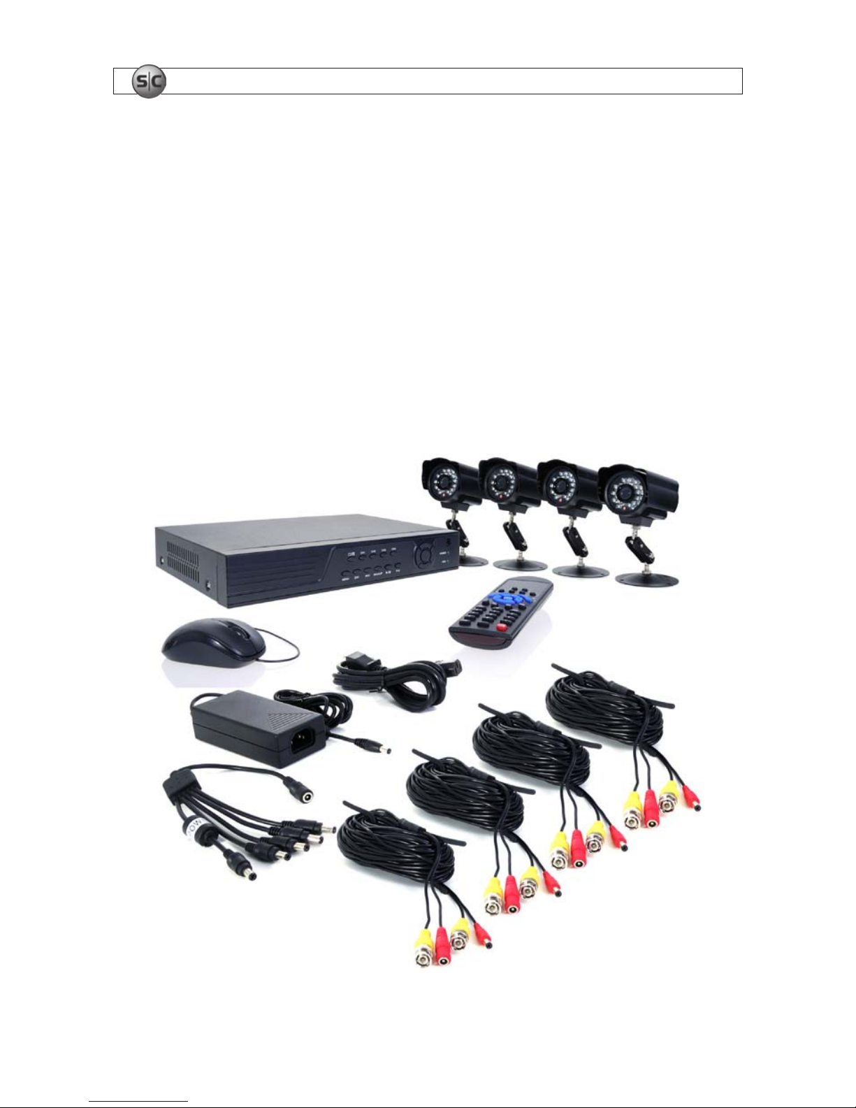
Your system includes:
• 4 channel H.264 networkable DVR
• Cameras (camera type(s) depend on system model and options)
• 4 – 60’ video/power extension cables
• Power adapter with 5-way splitter
• This manual, mini-CD with smart phone applications, user guides for cameras (on CD), and monitor (if included)
• USB mouse and remote control
• LCD Monitor (with SYRF204BLCD, SYRF204BHR systems, not shown)
Remove the equipment from its packaging and place it on a at, clean surface. Inspect each item. If any visible damage is present,
contact your supplier or Supercircuits for a replacement. Verify that your order is complete.
Cameras
5-way
Splitter
Mouse
Remote
Control
Video/Power
Extension Cables
DVR
Power
Adapter
Basic System Components (Monitor Not Shown)

3
4-Camera H.264 Security System Setup Guide
SECTION 2: GETTING STARTED: UNPACKING THE EQUIPMENT
What you need
Although each security system installation is dierent, most require the following items not included with your system
components:
• Tools to install the cameras and route power and video cables
• Fasteners to attach the cameras to the mounting surfaces
• A display device and cabling to connect to monitor the DVR. The DVR will connect directly to a VGA video monitor, or to a TV
with a BNC to RCA adapter and RCA cable. The display device is usually needed only for system setup. It can be disconnected
when the DVR is networked for access across a LAN or Internet.
• Uninterruptible power supply (UPS). This device is used to ensure system stability during voltage surges, sags, and outages. If a
UPS is not available, a power strip with strong surge protection is highly recommended.
4
www.supercircuits.com
SECTION 3: INSTALLING YOUR SYSTEM
SECTION 3
Installing Your System
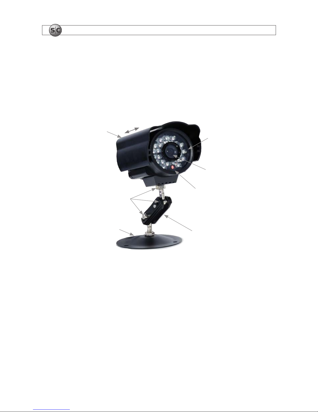
Your PC177IR series camera is a precision instrument that will provide years of quality service when used properly. Included with
each camera is:
• An adjustable mounting bracket that can be attached to either the bottom or back of the camera.
• 60’ video and power extension cable
Adjustable
Sun Shield
Lens
Mounting
Bracket
Assembly
Lock
Nuts
IR Array
Light
Level
Sensor
Mounting
Plate
3.1.1 Camera placement
Plan your camera installation carefully. Identify the locations where cameras will provide the best coverage, considering:
• Field of view – Cameras must be positioned so they can eectively view the entire area that must be monitored, and in a
location that makes tampering with it dicult.
• Lighting – Direct sunlight shining on the camera lens or bright reections from shiny objects in the eld of view can diminish
video quality and camera performance. Mount the camera in shaded areas, if possible, or where these inuences can be
minimized.
• Ease of installation – Must be able to install the camera at the location, considering mounting hardware requirements,
temperature, dust, moisture, etc.
5
4-Camera H.264 Security System Setup Guide
SECTION 3: INSTALLING YOUR SYSTEM
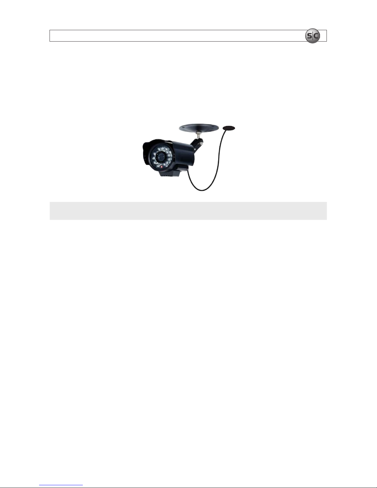
About weatherproof cameras
Weatherproof cameras can be mounted in any open area, such as on a telephone pole or on the side of a building. However, for best
results, we recommend you mount your cameras in a sheltered area, such as under the eave or roof of a building. Point the camera in
the direction you wish to observe. When routing cable near the camera, allow enough slack to form a U-shaped “drip loop” to help
direct moisture or rain water, that accumulates on the cable, away from the camera.
Drip Loop
Drop
Cable
NOTE
Cable connections are not weatherproof.
Video/power cables can be run almost anywhere, and are frequently routed through attics or above drop/acoustic ceilings because
of the ease of installation. For added security, we recommend you run your cables in areas with limited access to prevent tampering.
Avoid running the cable near high voltage appliances such as uorescent lighting. Electrical noise and magnetic elds produced by
these devices may aect video signal quality.
A 60’ video/power extension cable is shipped with every camera in your system. 100’ and custom-length cables are also available
from Supercircuits.
3.1.2 Mounting
1. Using the camera bracket mounting assembly plate as a template, mark the location of the holes for the mounting screws on
the mounting surface.
2. Drill holes into the mounting surface for the mounting screws, wall inserts, or other attachment hardware as needed.
3. If you are routing the video/power drop cable through the mounting surface, drill a ¾” hole near the mounting plate for the
drop cable.
4. Attach the mounting bracket to the mounting surface using appropriate fasteners.
5. Attach the camera with the mounting bracket.
6
www.supercircuits.com
SECTION 3: INSTALLING YOUR SYSTEM
6. Point the camera at your surveillance target, then tighten the lock nuts to hold it in place. (Note: The direction the camera is
pointing may need correction when video from the camera is observed.)
7. Route the camera drop cable through the hole drilled for it in the mounting surface, if used. If the camera is installed where
moisture may accumulate on it, leave a “drip loop” in the cable so that beads of water on the cable slide away from the camera
and the drop cable connectors.
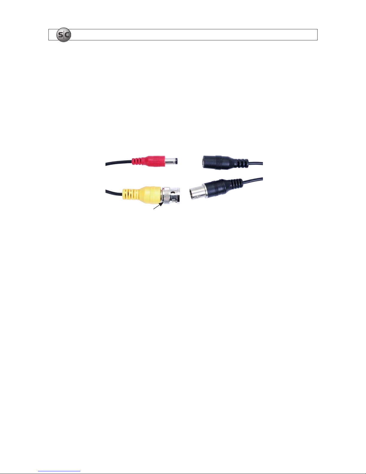
8. Attach a video/power extension cable to the camera drop cable (see diagram below). Note: When connecting the video
cables, fully rotate the lock ring to hold them together.
Extension
Cable
Camera
Drop Cable
Power
Video
Lock Ring
If the connectors might be exposed to moisture or other contaminants, seal them with electrical tape or use an equivalent
method.
9. Route the other end of the video/power extension cable to the DVR backpanel.
10. Repeat this procedure for all of the cameras you are installing.
3.1 DVR installation
3.1.1 Placement
Your monitoring and recording equipment is central to constant surveillance and the reliable capture of video evidence. Supercircuits
strongly suggests that it be installed in a secure location with access limited to authorized personnel.
DVRs generate heat and should be placed in a ventilated area. A high temperature environment will reduce the life span and
reliability of the equipment. Additionally, the DVR is not weatherproof, so avoid exposure to liquids and excessive dust. Do not place
objects along the sides or behind the DVR that will block airow through the unit.
7
4-Camera H.264 Security System Setup Guide
SECTION 3: INSTALLING YOUR SYSTEM
Uninterruptible power supplies
It is strongly suggested that power to the system be routed through an uninterruptible power supply (UPS). These devices will keep
your security system running through most power outages, in addition to providing excellent surge and sag protection. The UPS
should support your video recorder and all cameras to ensure normal operation during abnormal power conditions.
3.1.2 Controls and connectors
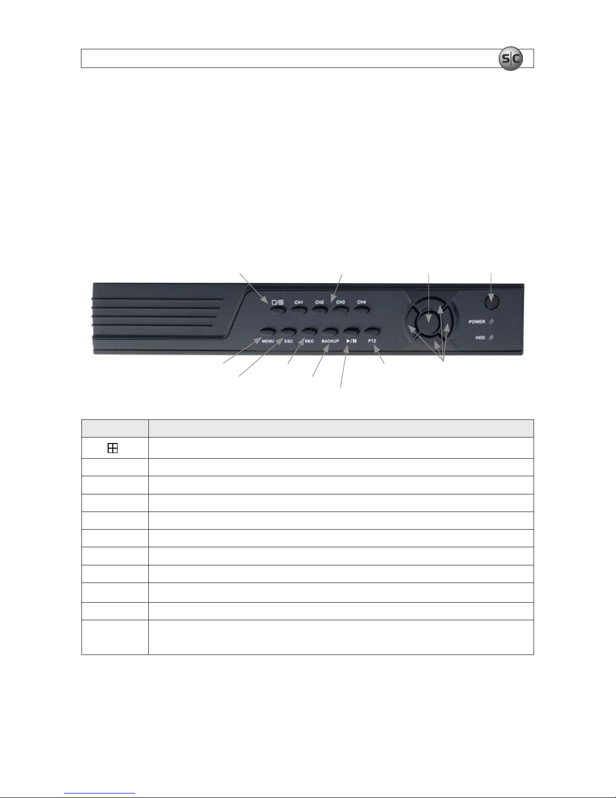
DVR Front Panel
Single/Multi Camera
Display Toggle
tqpu Menu
Navigation
Buttons
Enter
Escape
Menu
Play/Pause
Record
CH1 .. CH4
Camera Select
Infrared
Sensor
Pan/Tilt/Zoom
Control
Backup
Button Usage
o /
Toggles between single camera, multi-c amera display.
CH1 .. CH4 Used to selec t the camera on c hannel 1, 2, 3, or 4.
Enter Press to conrm a menu cho ice.
Infrared Sensor Sensor for the remote control.
MENU Opens t he main menu window
ESC Press to exit any active window.
REC Use to start and stop manual recording.
BACKUP Opens a video search and playback menu. (See Appendix A)
u/II
When a recorded le is selected, press this but ton to play. then press it again to paus e playback.
PTZ Used for pan/tilt/zoom control of cameras wi th this feature.
t q p u
Use the se buttons to navigate throu gh the menu sys tem. Generally, use the t u buttons to move to
selec tion boxes, and use the
q p to select submenu parameters.
8
www.supercircuits.com
SECTION 3: INSTALLING YOUR SYSTEM
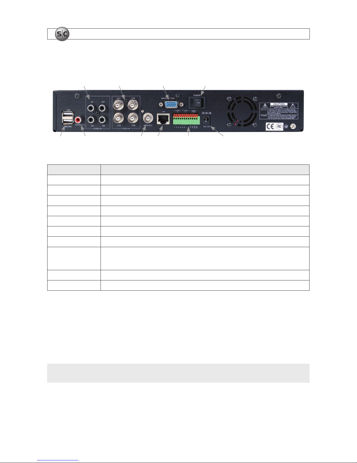
DVR Backpanel
IN1 - IN4
Audio In
CH1 - CH4
Video In
Audio Out LAN Main Out
(BNC)
Power
Alarm In/Out,
RS422/RS485
Connections
Main Out
(VGA)
USB Power DC 12V
Connector Usage
USB - MOUSE Use the se USB ports to conne ct a mouse, or a backup device such as a ash drive o r DVD recorder.
AUDIO OUT Audio output f rom channel AUDI O IN channels 1, 2, 3, or 4.
IN1 .. IN4 AUDIO IN RCA audio input to audio channels 1, 2, 3, and 4.
CH
1 .. CH4 VIDEO IN BNC video inpu t to video channels 1, 2, 3, and 4.
MAIN OUT BNC comp osite video output to display device (75Ω, 1V p-p).
MAIN OUT VGA Standard VGA out put to a display device, suc h as a computer monitor.
LAN Standard RJ45 Ethernet 10BaseT, 100BaseT port with auto detect.
ALARM IN, ALARM OUT,
RS422 RS485
Use the se connecto rs to attach e xternal sensor de vices, alarm reporting de vices, and devices with an RS 422 or RS485 control
inter face, such as PTZ camer as. See the DVR Uer Manual f or more information.
DC 12V Connec t to 12 VDC power adapter.
POWER Power switch to turn the unit on an d o.
3.2 Install and setup a monitor
1. Install and setup your monitor in accordance with the instructions provided with the monitor. Do not power it on at this time.
2. Cable the DVR Monitor Out (VGA) connector to your monitor’s VGA input. You can also use the monitor out BNC interface, but
the signal quality is better through the VGA interface.
NOTE
Some monitors have multiple inputs such including VGA ,HDMI, BNC, etc. If you are using this kind of monitor, congure your
monitor to display the input from your DVR.
9
4-Camera H.264 Security System Setup Guide
SECTION 3: INSTALLING YOUR SYSTEM
Monitor Out
(BNC)
Monitor Out
(VGA)
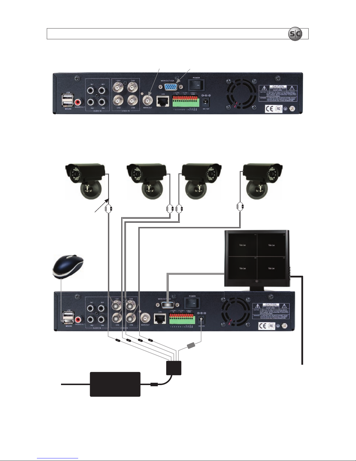
3.3 Connecting the system together
All connections to the DVR are made on the back of the unit.
Video/Power
Extension Cables
VGA Cable
5-Way
Power
Splitter
To 120 VAC
Monitor Power
Power Adapter
Mouse
Camera
Drop Cable
To UPS/
120 VAC
Typical Interconnection Diagram*
10
www.supercircuits.com
SECTION 3: INSTALLING YOUR SYSTEM
* NOTE: Power cabling shown in the previous diagram is recommended for systems with PC177IR series cameras. If you are not
installing PC177IR series cameras, power requirements for your cameras may be dierent. Refer to the documentation provided
with your camera for specic recommendations.
1. Connect the system mouse to the USB connector labeled MOUSE.
2. Connect the camera video signal cables (BNC connectors) to the VIDEO IN CH1 to CH4 connectors
3. Connect a display device to the DVR. If using a VGA monitor for a display, connect it to the VGA MAIN OUT connector. If using
the BNC MAIN OUT connector to drive a display such as a TV, attach the appropriate cables between the BNC MAIN OUT and
your display device.
4. Connect the 5-way power splitter to the power adapter, then:
a. Connect the lead marked DVR POWER to the DC 12V connector on the DVR backpanel. Ensure that the POWER switch
on the DVR is o.
b. Connect the other leads of the splitter to the mating connectors on the video/power extension cables routed to the
cameras.
5. Connect the power cord to the power adapter and plug it into a standard grounded 120 VAC power source through a UPS or
surge protector.
6. Power on your system monitor.
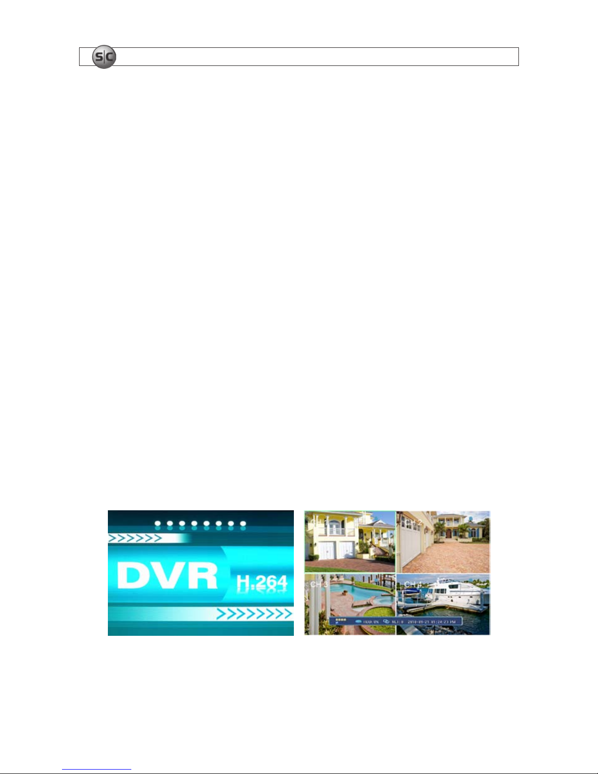
7. Power on the DVR using the POWER switch on the backpanel. A startup “Loading” screen will appear on the display. After a
few seconds, the screen will change to the camera view screen.
..
Note: The images you see from your cameras may be dierent from those shown here.
11
4-Camera H.264 Security System Setup Guide
SECTION 3: INSTALLING YOUR SYSTEM
3.4 Adjusting the camera
Adjust your camera to produce the best performance:
• While observing video from your camera, use the documentation provided to aim the camera at the surveillance target.
• Depending on the features of your cameras, other adjustments, such as focus, zoom, aperture, IR level, etc. may also be
available. Make these adjustments under various lighting conditions, if necessary, to yield the best video image overall.
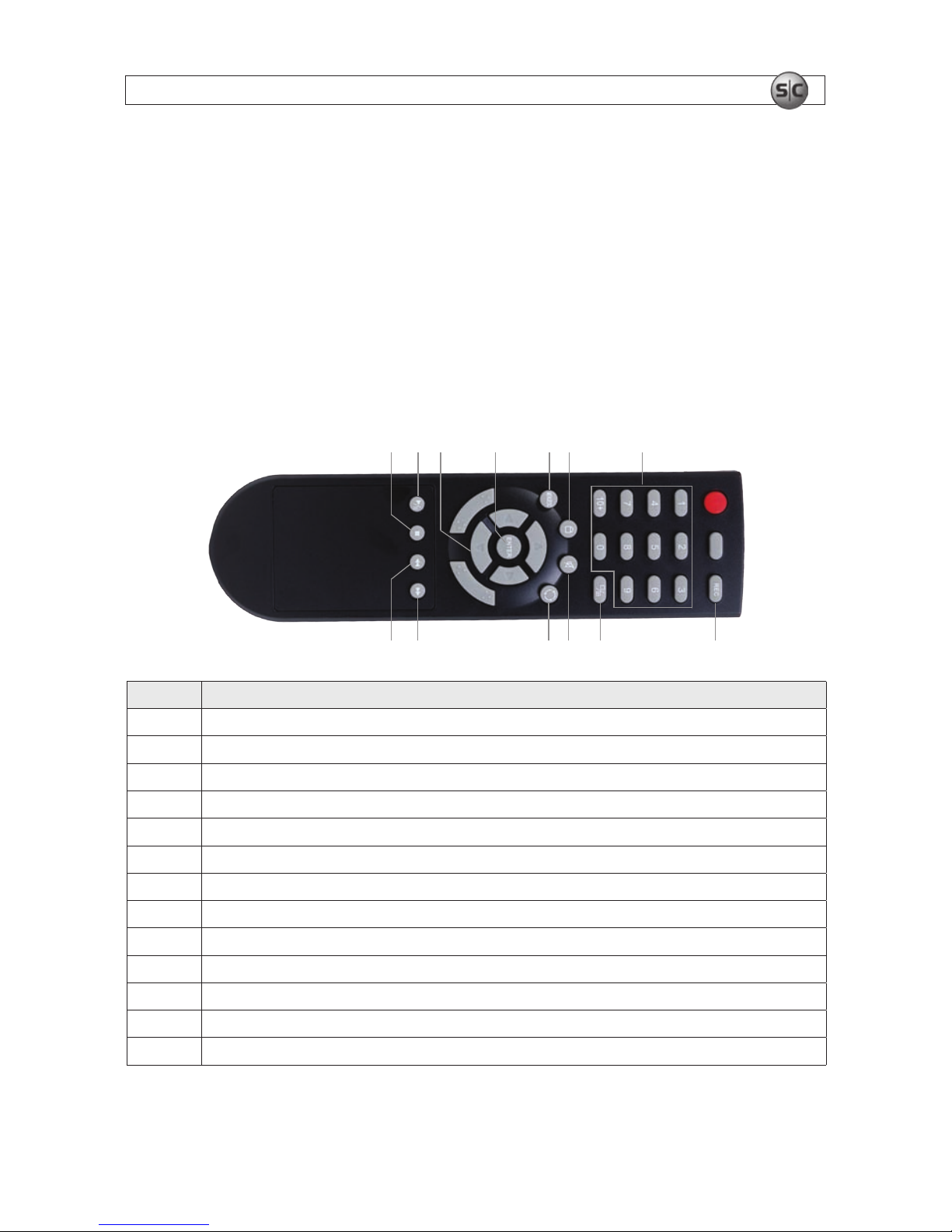
3.5 Using the remote control and mouse
The enter key on the remote control or the front panel has the same function as a mouse left click. The IR Range of the remote
control is 10 meters. The buttons on the remote control correspond with the buttons on the front panel.
2 31
89
75 64
111213 10
Item Function
1 Stop: Stop p layback
2 Play/Pause: Opens video search and playbac k menu. In playbac k mode, press this but ton to play/pause playbac k.
3
t q p u Move selected item in menu.
4 ENTER: This but ton is used as the “enter” key for most op erations.
5 Menu (MENU/ESC): Displays/exits th e main menu.
6 Lock: If the p assword is enabled, press it to logout the system.
7 Numer ical Button: Use buttons 1, 2, 3, or 4 to select the channel to display.
8 REC: Start or Stop manual recording.
9 Quad: Press this but ton to switch display modes f rom single chann el display to a multi-channel display.
10 Mute: Not used.
11 Spot View: Press to enable auto s equencing.
12 Fast For ward: Fast for ward video during playback.
13 Rewind: Rewind vide o during playback.
12
www.supercircuits.com
SECTION 3: INSTALLING YOUR SYSTEM
Mouse control
The mouse operates just like a mouse on a Windows PC. Connect the mouse to the USB connector in the back panel.
Action Eec t
Right click
In live display mod e, right click to ei ther display or hide the to ol bar.
In main menu or sub menu mode, r ight click to exit the current menu. Note that the set tings will not b e saved after right c licking.
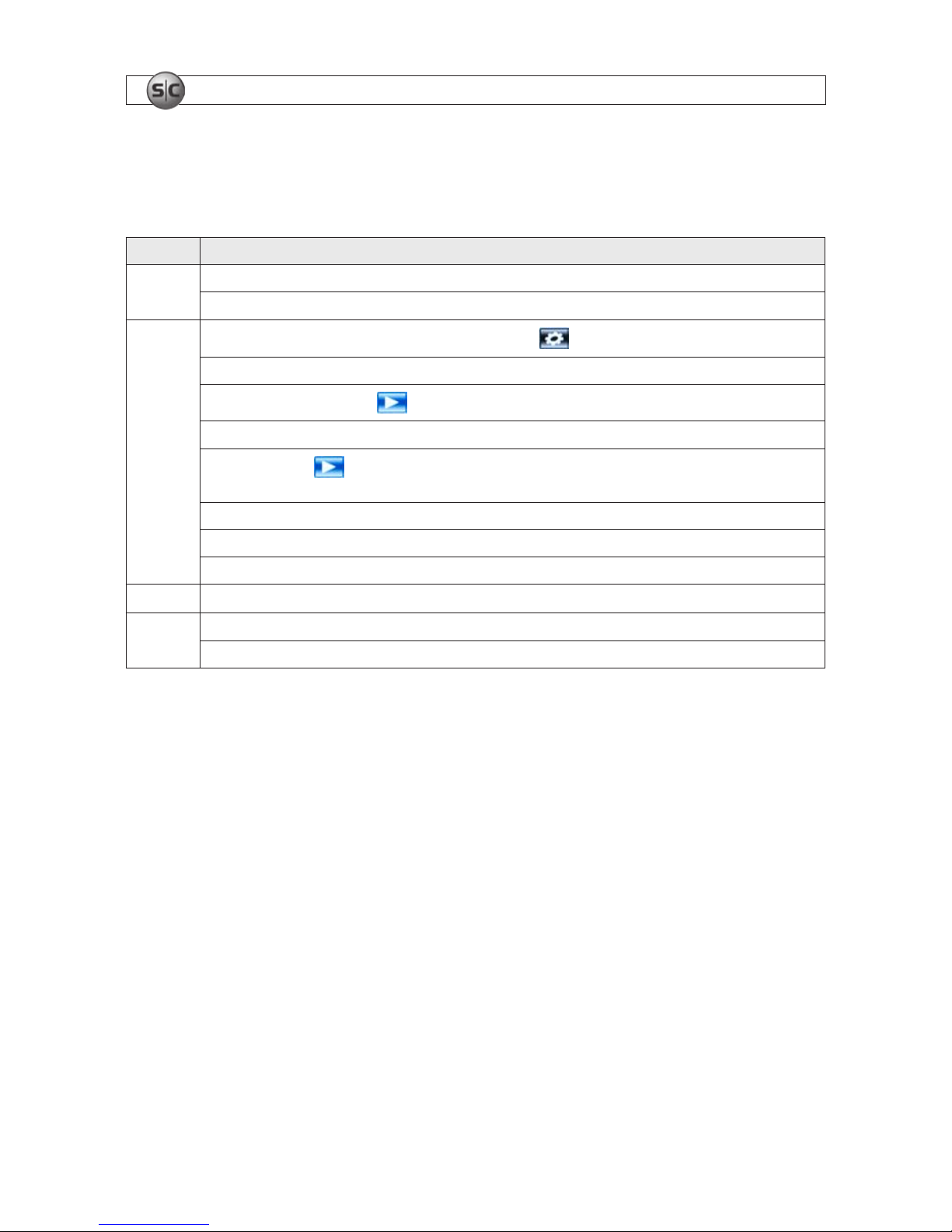
Left click
On menu unlock mode, in the tool bar lef t click on the SYSTEM SET TINGS icon,
, to enter into the main menu.
After entering main menu, lef t click to enter sub menus.
In menu mode, lef t click the PLAY icon, , to review vide o les.
Left click to s elect value s in edit boxes or pull-down menus. The system supp orts special sy mbols, number s and letter s.
Left click the PLAY icon, , to enter playback mode. Lef t click >> to control the forward func tion, << rever se function, >>I Slow play
func tion, I> frame play functio n, > Play function, and X e xit function.
In the VID EO | VIDEO SETUP | COLOR SETUP conguration window, you can left click to adjust color control bar and screen control b ar.
In the main menu, sub menu or playback view, lef t click “x” to e xit/close the current menu.
In the ALARM |MOTION | MD AREA conguration window, left click an area segment to selec t/deselect it for motion sensing.
Double click In live view or during video playback, double-click to maximize channel on the screen.
Mouse drag
In the ALARM |MOTION | MD AREA conguration window, press the left mouse but ton and drag to frame an area to sense for motion detec tion.
Use the mouse to s elect menu items.
13
4-Camera H.264 Security System Setup Guide
SECTION 4
DVR Setup
Setting up your DVR includes logging into your DVR, setting the clock, setting administrator and user account passwords, and
setting up scheduled and/or automated motion recording.
4.1 Login to the DVR
Two access accounts are preset in your system: Admin and user1. With the Admin login, you can make conguration changes to
the system, create user accounts and passwords, and control the privileges allotted to each account. With the factory default user1
account login you cannot make conguration changes or create accounts, but can change your own password. The factory default
Admin and user1 account passwords are:
Admin: 888888
user1: 666666
To log into the system:
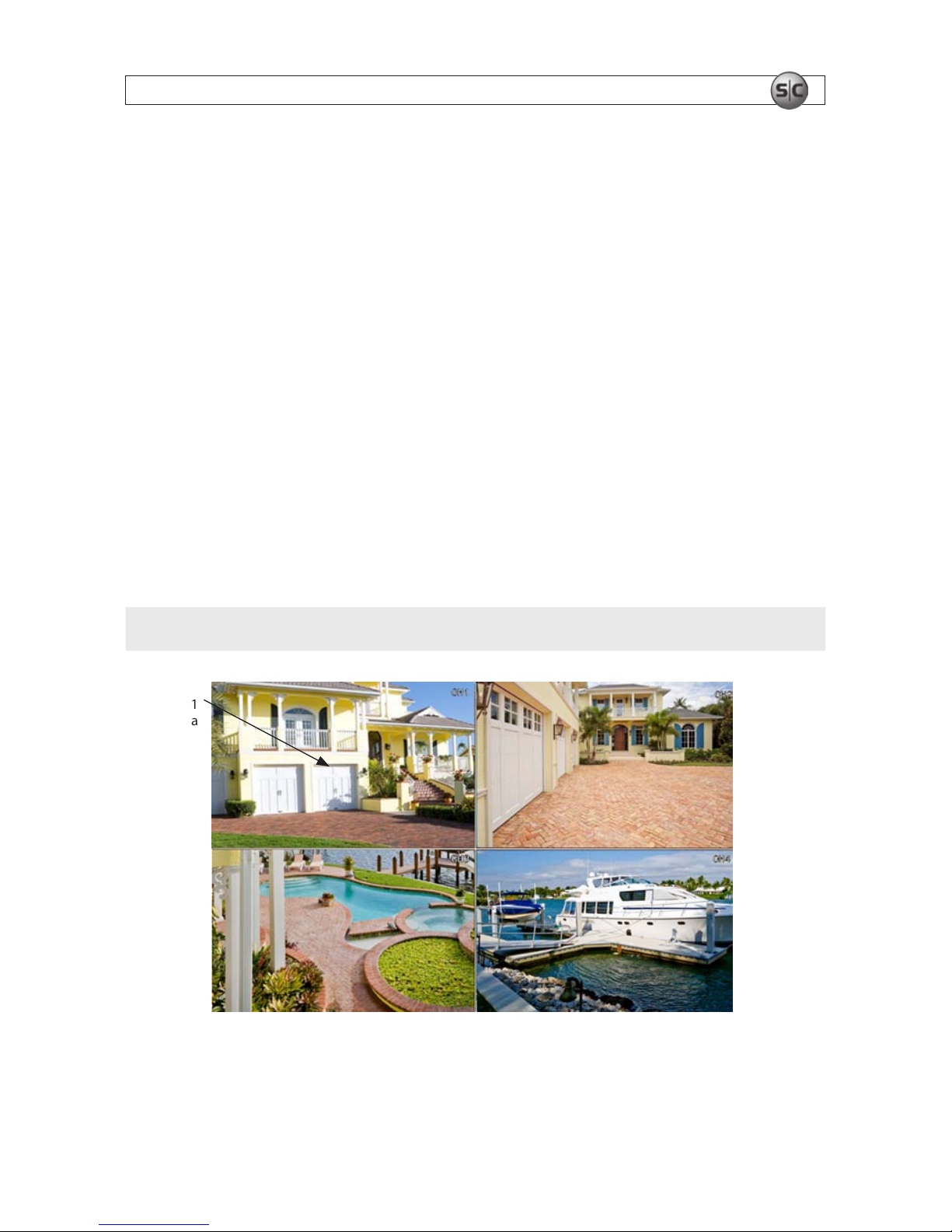
1. Power on the DVR and wait until it advances to the camera view screen. A typical camera view screen is shown below.
NOTE
During initial startup of the system, no password is required.
Image from
Channel 1
Camera
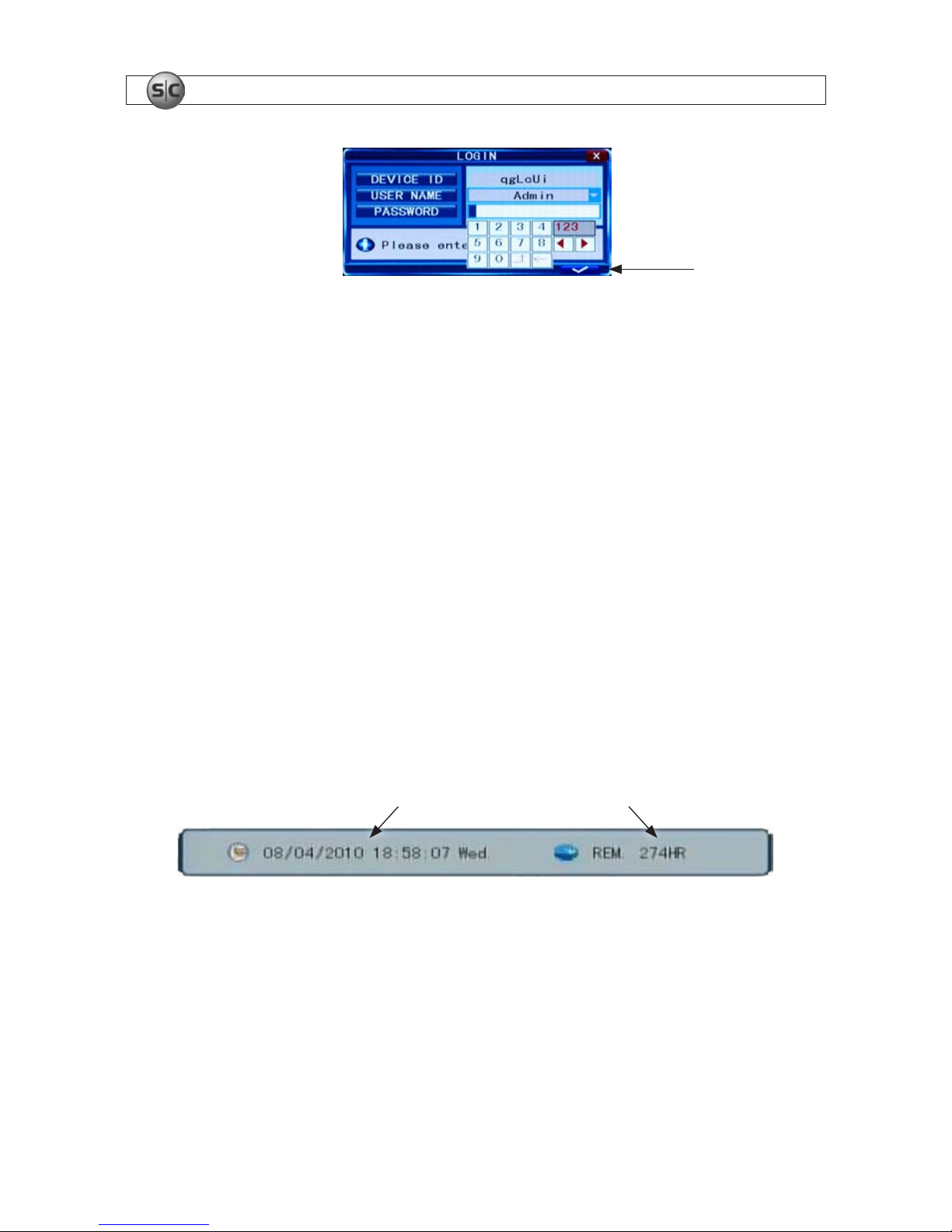
2. Press the MENU button on the front panel twice, or right-click the mouse twice anywhere on the screen. An Input
Password window will appear.
SECTION 4: DVR SETUP
14
www.supercircuits.com
SECTION 4: DVR SETUP
Conrm entry
3. Click the q icons to the right of the User Name eld parameter eld and select Admin. To make conguration changes to the
system, you must login to the Admin account.
4. Using the mouse, click the entry eld on the PASSWORD line, then click the number buttons that appear to enter the account
password. For example, to enter the default Admin password, 888888, click the “8” button six times.
5. Click the a (check mark) icon in the lower right corner of the window to conrm your entry and enter the login information.
A tool bar icon strip will appear at the bottom of the screen.
4.2 Conguring the system
Basic system conguration settings include setting the screen language, video system format, system time, creating users,
initializing the hard disk drive (HDD), and setting up automated recording.
1. If the system is not running, power on the DVR and wait until it completes initialization.
2. Right-click anywhere on the desktop, or press the MENU button. A status bar will appear.
3. Compare the DVR system date and time shown on the Status Bar with an accurate clock.
System Date and Time Remaining HDD Recording TIme
Status Bar
Note: To see an accurate clock, access a reliable Internet time server, such as
tf.nist.gov
4. Right-click the mouse anywhere on the screen again. The Status bar will change to a Tools Bar or a login window. If a LOGIN
window opens, log in to the system as an Admin (see above).
15
4-Camera H.264 Security System Setup Guide
SECTION 4: DVR SETUP
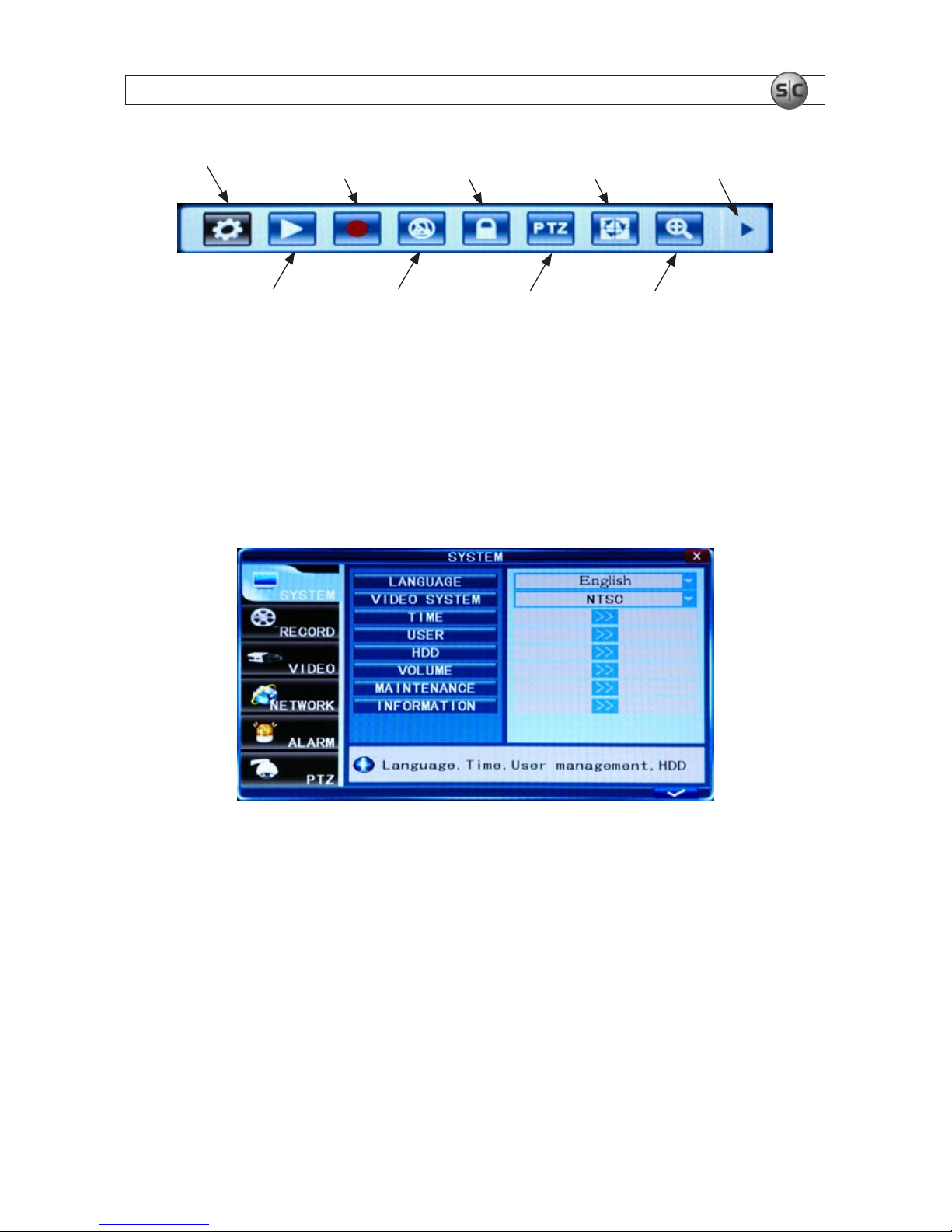
System Settings
EZoomPTZ
Play
Manual Record /
Stop Manual Record
Auto
Sequence
Advance
Keylock
Mute On/O
Tool Bar
5. Click the Settings button on the Tool Bar.
4.2.1 Setting the screen language and video system format
1. In the Settings window SYSTEM tab, click the q icon at the right end of the LANGUAGE line. Select (click) the screen
language you prefer from the dropdown list.
2. If the VIDEO SYSTEM option does not indicate NTSC, click the q icon at the right end of the VIDEO SYSTEM line, then select
NTSC from the dropdown list.
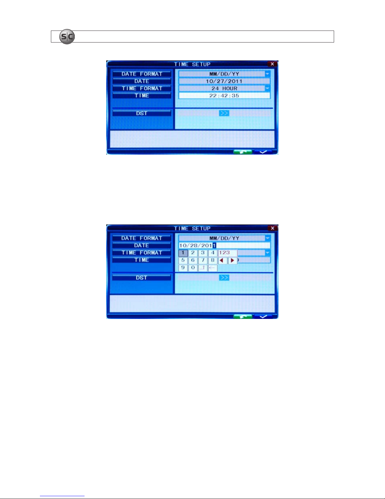
4.2.1 Setting the system time
1. On the TIME line, click the >> icon to open the TIME SETUP window.
16
www.supercircuits.com
SECTION 4: DVR SETUP
2. Click the q icon at the right end of the DATE FORMAT line. Select the format you prefer: MM/DD/YY, YY-MM-DD, or DDMM-YY.
3. Click the entry on the DATE line. Click the t or u icons to highlight a digit of the date, then click the number value of the
digit To complete the entry and close the virtual keyboard, click the = button.
4. Click the q icon at the right end of the TIME FORMAT line. Select the format you prefer: 12 hour or 24 hour.
5. Click the entry on the TIME line. Click the t or u icons to highlight a digit of the current time, then click the number value of
the digit. To complete the entry, click the = button.
6. If you selected a 12 hour time format, click the q icon on the line below the TIME entry, then select either AM or PM.
7. On the DST line, click the >> icon to open the DST (ON/OFF) option window. If you select ON, a DST setup window will open.
Use the method like that detailed above to setup the DST start and end time, then click the conrm entry check (
a) in the
lower right corner to conrm your entries.
8. Click the CONFIRM button in the NOTE window.
17
4-Camera H.264 Security System Setup Guide
SECTION 4: DVR SETUP
4.2.2 Change the Admin and user1 passwords
Changing the default Admin and user1 account passwords from their initial (default) value adds security to your system. The
factory default account names and their passwords are:
Admin: 888888
user1: 666666
To change these passwords:
1. With the system powered on, right click twice on the desktop or press the menu button on the front panel twice, then log into
the system as the Admin (if a password login is required).
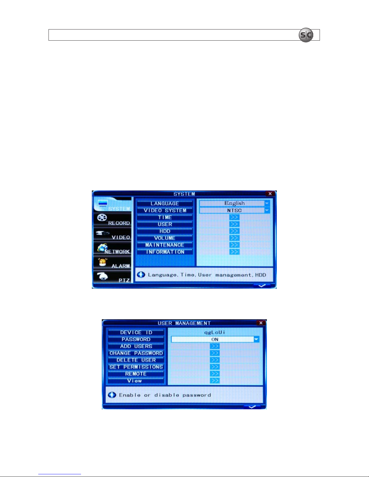
2. Click the Settings icon on the Tool Bar. The SYSTEM tab window will open.
1. On the USER line, click the >> icon to open the USER MANAGEMENT window.
18
www.supercircuits.com
SECTION 4: DVR SETUP
2. On the CHANGE PASSWORD line, click the >> icon to open the CHANGE PASSWORD window.
3. Click the q icon at the right end of the USER NAME line. From the dropdown list, select Admin.
4. Click the OLD PASSWORD entry eld, then enter the current Admin password using the virtual keyboard.
5. Enter both the NEW PASSWORD and CONFIRM PASSWORD elds with a dierent password. Passwords cannot be more
than 6 digits in length.
6. Click the conrm icon (a) in the lower right corner of the screen, then click the Conrm button in the Note window.
7. Repeat steps 3, 4, 5, and 6 above to change the user1 password.
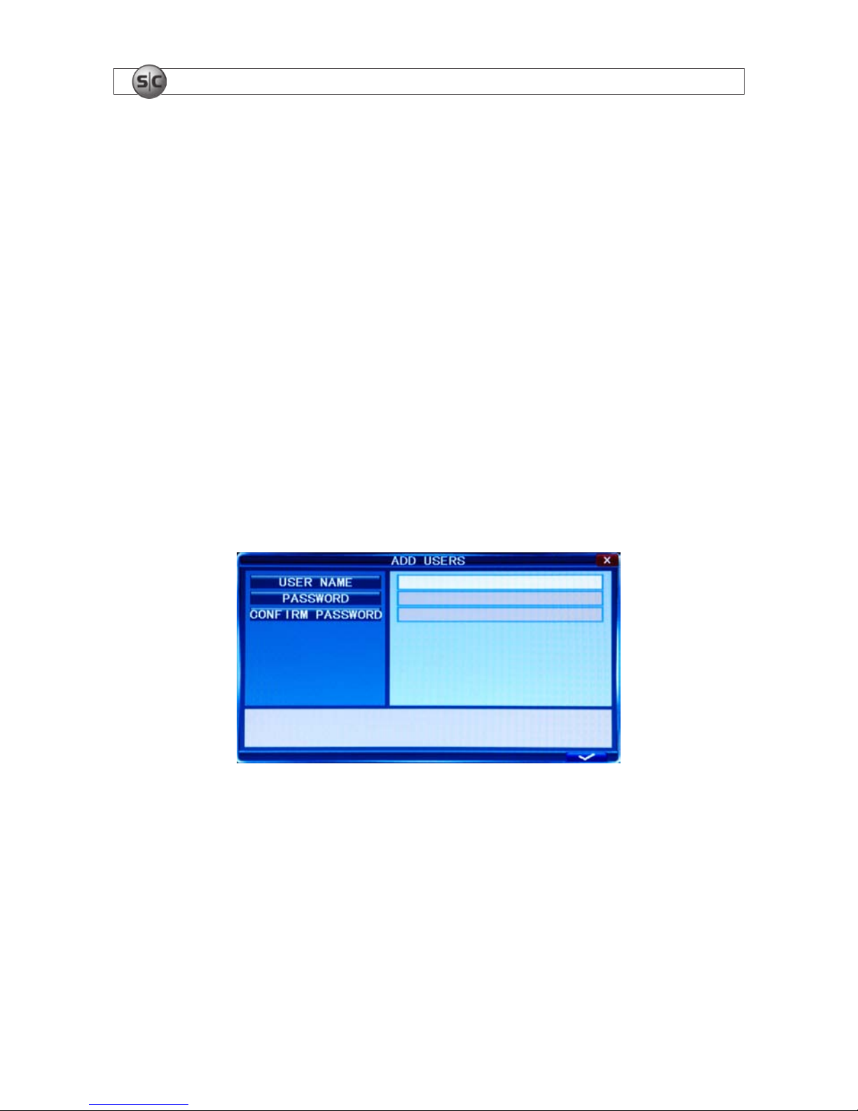
4.2.3 Add users to the system
1. On the SYSTEM tab USER line, click the >> icon to open the USER MANAGEMENT window.
2. In the USER MANAGEMENT window, click the >> icon on the ADD USER line.
3. Click the entry eld on the USER NAME line to open a virtual keyboard. Click the letters and numbers to enter a username,
then click the = icon to close the keyboard.
4. Enter both the PASSWORD and CONFIRM PASSWORD elds with a password for the user. Passwords cannot be more than
6 digits in length.
5. Click the conrm icon (a) in the lower right corner of the screen, then click the Conrm button in the Note window.
6. Press the MENU button on the front panel or right click on the desktop to return to the USER MANAGEMENT window.
19
4-Camera H.264 Security System Setup Guide
SECTION 4: DVR SETUP
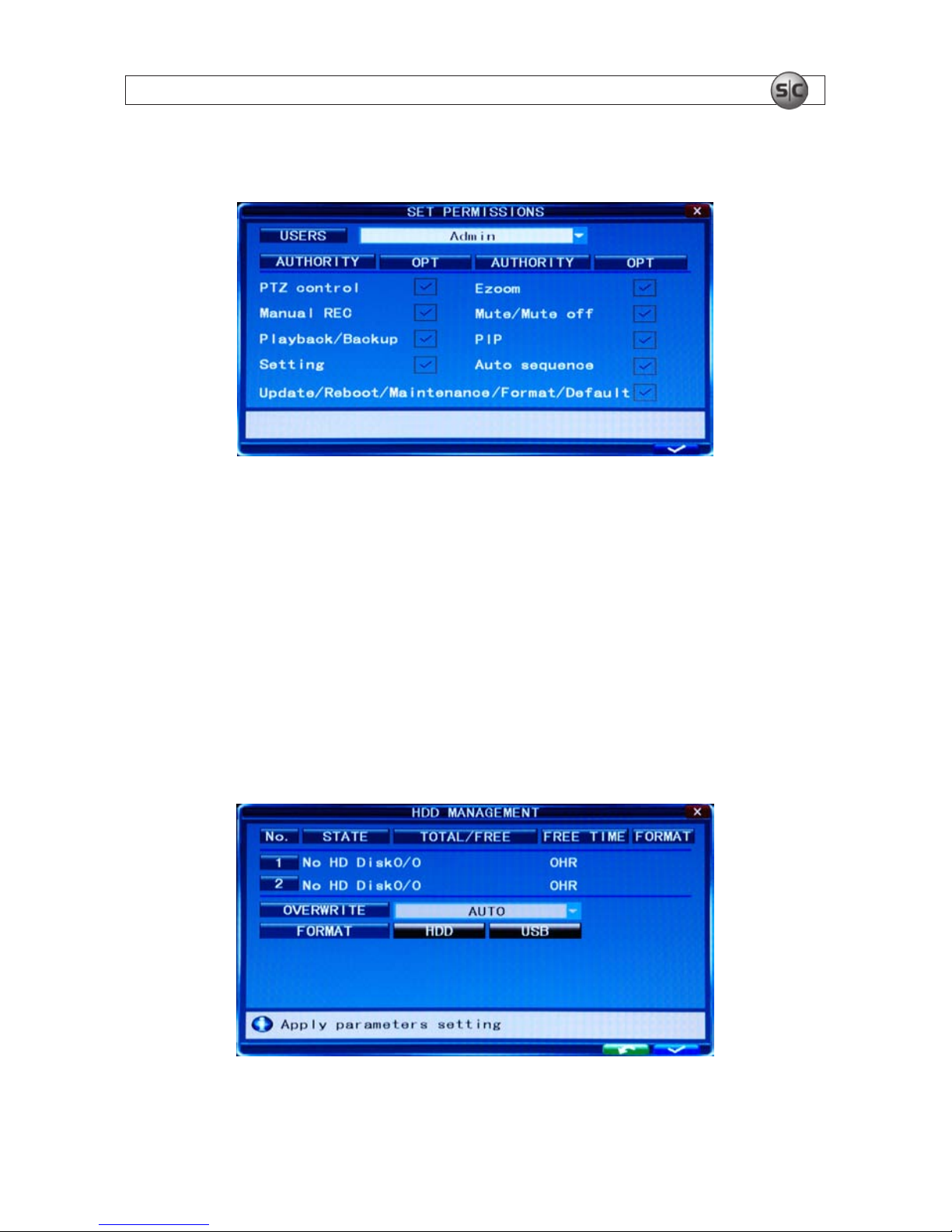
7. In the USER MANAGEMENT window, click the >> icon on the SET PERMISSIONS line.
8. Click the q icon at the right end of the USERS line. From the dropdown list, select the name of the user you just created.
9. Click the OPT checkboxes to assign permissions to the new user.
10. Click the conrm icon (a) in the lower right corner of the screen, then click the Conrm button in the Note window.
11. Press the MENU button on the front panel to return to the USER MANAGEMENT window, then press the MENU button again
to return to the SETTINGS window SYSTEM tab.
4.2.4 Set HDD overwrite option
1. On the SYSTEM tab HDD line, click the >> icon to open the HDD MANAGEMENT window.
2. Click the q icon at the right end of the OVERWRITE line. From the dropdown list, select the option you prefer:
20
www.supercircuits.com
SECTION 4: DVR SETUP
Close: When the HDD becomes full, no additional recordings are written to the HDD
Overwrite: Recordings on the HDD are overwritten when the HDD becomes full. The oldest recording is overwritten
rst.
1 HOUR .. 90 DAYS: Recordings are overwritten when older than the time selected.
3. Click the conrm icon (a) in the lower right corner of the screen, then click the Conrm button in the Note window.
4. Press the MENU button on the front panel or click on the desktop to return to the SYSTEM tab.
4.3 Record conguration settings
The recording settings of each camera channel can be specied separately or collectively. These settings, including the recording
schedule for each channel, are setup through the Record tab.
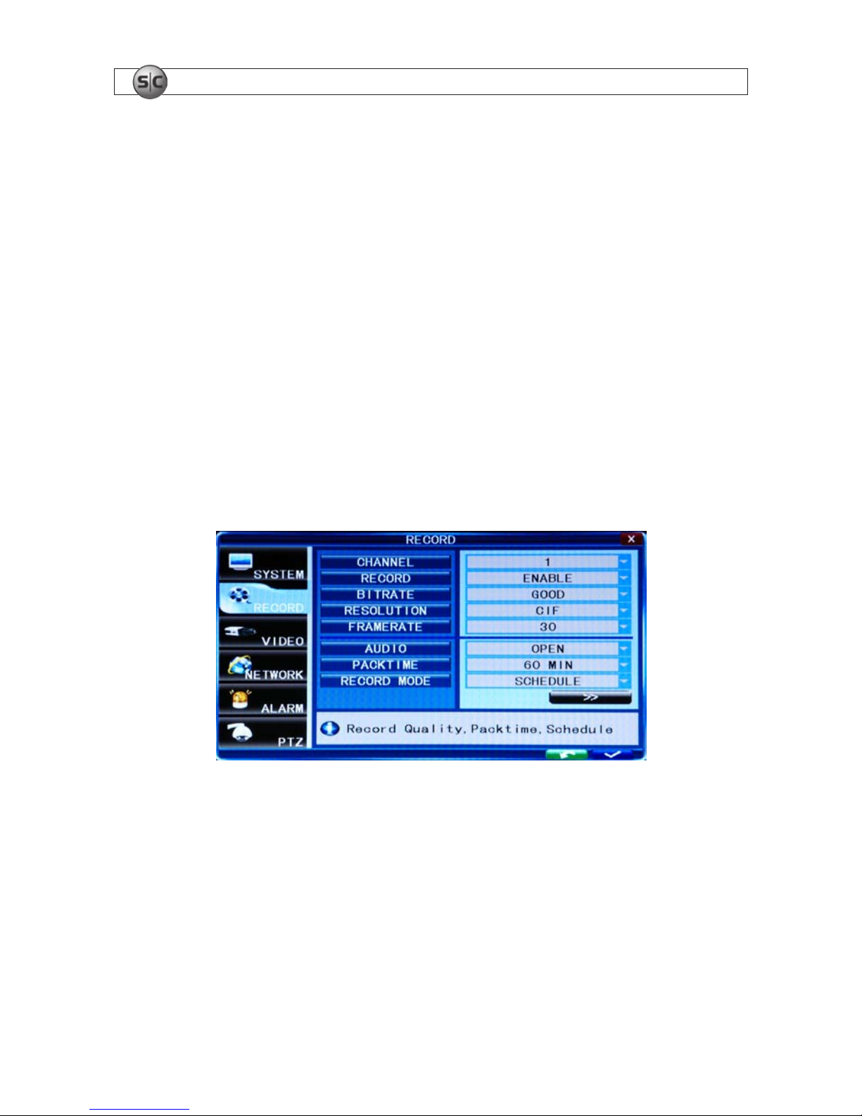
1. Click the Settings icon on the Tool Bar. The SYSTEM tab window will open.
2. Click RECORD to open the RECORD settings menu.
3. Click the q icon at the right end of the CHANNEL line. From the dropdown list, select the number of the camera channel you
want to setup, or select ALL to congure all channels with the same settings.
4. Click the q icon at the right end of the RECORD line. From the dropdown list, select DISABLE, or ENABLE to record video from
the channel.
5. Click the q icon at the right end of the BITRATE line. Select GOOD, NORMAL, or LOW. A GOOD bitrate produces the best
recording quality, but uses more processing power and hard disk space.
21
4-Camera H.264 Security System Setup Guide
SECTION 4: DVR SETUP
6. Click the q icon at the right end of the RESOLUTION line. From the dropdown list, select D1 (720 × 486), HD1 (720 ×
240), or CIF (352 × 288).
7. Click the q icon at the right end of the FRAME RATE line. From the dropdown list, select a number between 1 and 30
(frames per second). The higher the frame rate (30 fps), the smoother the video motion. However, higher frame rates consume
storage space faster.
8. Click the q icon at the right end of the PACKTIME line. From the dropdown list, select either 15, 30, 45, or 60 (minutes).
Packtime is the time length of video le segments that are o-loaded (backed up).
9. Click the q icon at the right end of the RECORD MODE line. From the dropdown list, select either ALWAYS or SCHEDULE.
ALWAYS causes the DVR to record continuously. Selecting SCHEDULE allows you to open a window to congure the DVR to
record by the hour of the day and day of the week, either by motion sensing, continuous recording, or not recording. See
Scheduled recording below.
10. If you are conguring the camera channels dierently, repeat this procedure for the other camera channels.
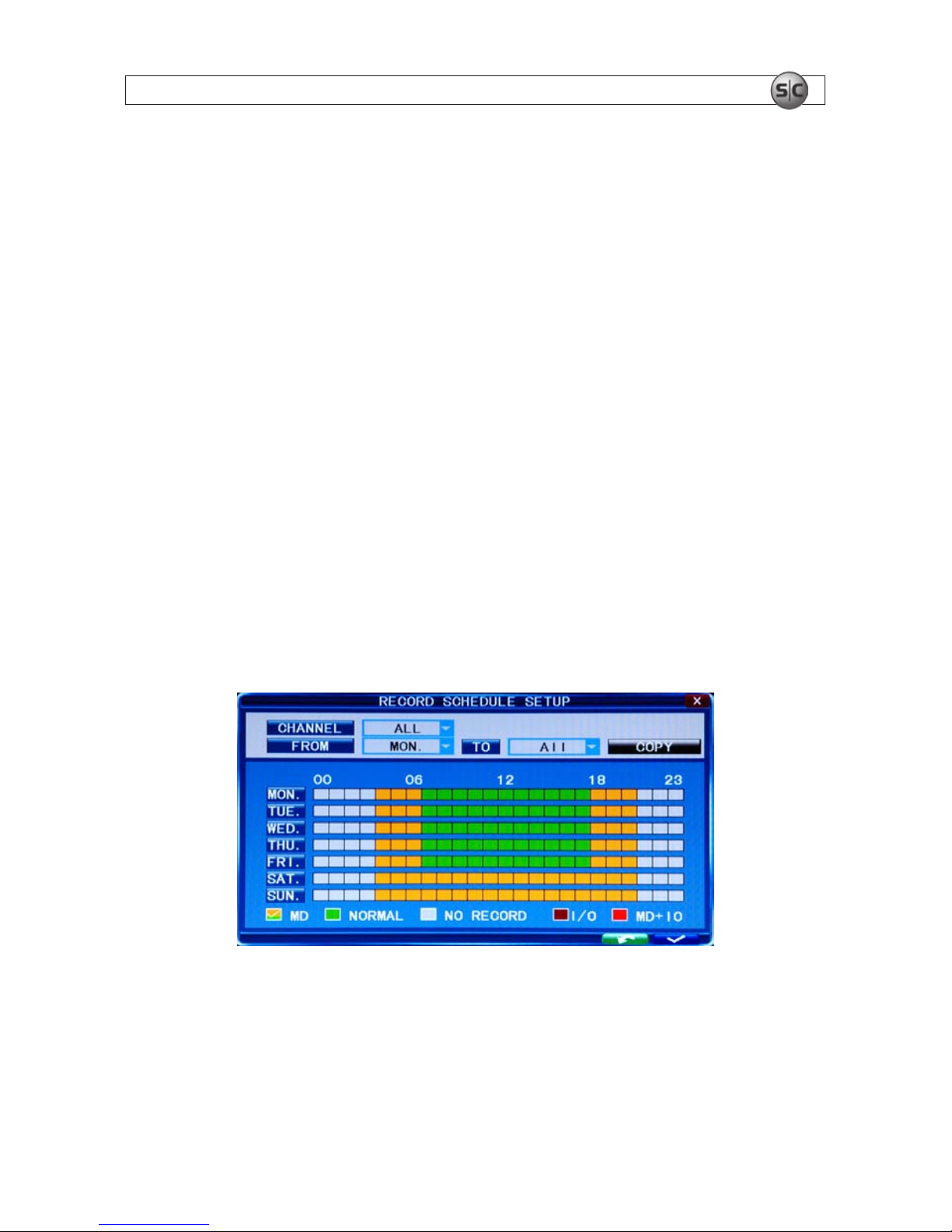
Scheduled recording
If the RECORD MODE -SCHEDULE is selected:
11. Click the >> icon on the RECORD tab to open the RECORD SCHEDULE SETUP window.
12. Click the q icon at the right end of the CHANNEL line. From the dropdown list, select the channel number to apply the
recording schedule to, or select ALL to apply the schedule to all cameras.
13. At the bottom of the window, click either the MD (motion detection) or NORMAL (continuous recording) checkbox, then click a
box in the time array to apply that method of recording to that timeslot.
 Loading...