

Super Circuits SYRF04, SYRF04LCD Installation And Setup Manual
4-Camera Day/Night H.264
Security System
Installation and Setup Guide
Products: SYRF04, SYRF04LCD
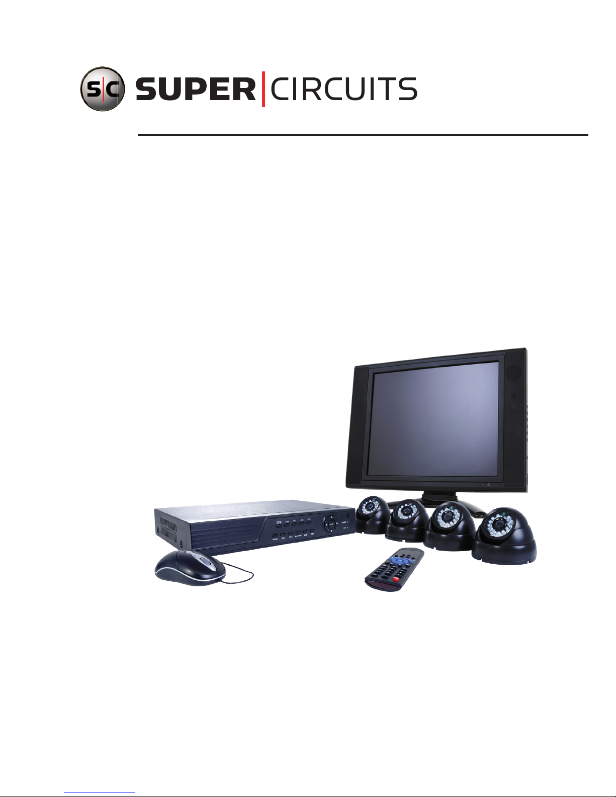
SYRF04LCD System (shown)
PLEASE READ THIS MANUAL BEFORE USING YOUR SYSTEM, and always follow
the instructions for safety and proper use. Save this manual for future reference.
SYRF04-04LCD_QuickSetup

ii
www.supercircuits.com
CAUTION
Operate this device only in environments where the temperature or humidity is within the
recommended range. Operation at extreme temperatures or in very high or low humidity
levels may cause electric shock and shorten the life of the product.
CAUTION
Installation and servicing should be performed by qualied and experienced personnel only.
DVR should always remain OFF during any installation process.
CAUTION
Do not use the camera if fumes, smoke or a strange odor is emitted from the unit, or if it
seems to function incorrectly. Disconnect the power source immediately, and consult your
dealer.
LEGAL NOTICE
Supercircuits products are designed to meet safety and performance standards with the use of specic
Supercircuits authorized accessories. Supercircuits disclaims liability associated with the use of nonSupercircuits authorized accessories.
The recording, transmission, or broadcast of any person’s voice without their consent or a court order is
strictly prohibited by law.
Supercircuits makes no representations concerning the legality of certain product applications such as
the making, transmission, or recording of video and/or audio signals of others without their knowledge
and/or consent. We encourage you to check and comply with all applicable local, state, and federal laws
and regulations before engaging in any form of surveillance or any transmission of radio frequencies.
Other trademarks and trade names may be used in this document to refer to either the entities claiming
the marks and names or their products. Supercircuits, Inc. disclaims any proprietary interest in
trademarks and trade names other than its own.
No part of this document may be reproduced or distributed in any form or by any means without the
express written permission of Supercircuits, Inc.
© 2010 Supercircuits, Inc. All rights reserved.
11000 N. Mopac Expressway, Building 300, Austin, TX 78759
Sales/Support: 1.800.335.9777 | Fax: 1.866.267.9777

14-Camera H.264 Security System Setup Guide
Table of Contents
SECTION 1 Systems Overview . . . . . . . . . . . . . . . . . . . . . . . . . . . . . . . . . . . . . . . . . . . . . . . 2
1.1 About this document . . . . . . . . . . . . . . . . . . . . . . . . . . . . . . . . . . . . . . . . . 2
SECTION 2 Getting Started: Unpacking the Equipment . . . . . . . . . . . . . . . . . . . . . . . . . . . . 3
SECTION 3 Installing Your System . . . . . . . . . . . . . . . . . . . . . . . . . . . . . . . . . . . . . . . . . . . . 5
3.1 Camera installation . . . . . . . . . . . . . . . . . . . . . . . . . . . . . . . . . . . . . . . . . . 5
3.1.1 Camera placement . . . . . . . . . . . . . . . . . . . . . . . . . . . . . . . . . . . . . . . 5
3.1.2 Mounting . . . . . . . . . . . . . . . . . . . . . . . . . . . . . . . . . . . . . . . . . . . . . . 6
3.2 Install and setup the monitor (SYRF04LCD systems only) . . . . . . . . . . . 10
3.3 DVR installation . . . . . . . . . . . . . . . . . . . . . . . . . . . . . . . . . . . . . . . . . . . . 12
3.3.1 Controls and connectors . . . . . . . . . . . . . . . . . . . . . . . . . . . . . . . . . 12
3.3.2 DVR placement . . . . . . . . . . . . . . . . . . . . . . . . . . . . . . . . . . . . . . . . 13
3.4 Connecting the system together . . . . . . . . . . . . . . . . . . . . . . . . . . . . . . . 14
3.5 Aiming the Camera . . . . . . . . . . . . . . . . . . . . . . . . . . . . . . . . . . . . . . . . . . 15
SECTION 4 DVR Setup . . . . . . . . . . . . . . . . . . . . . . . . . . . . . . . . . . . . . . . . . . . . . . . . . . . . 17
4.1 Login to the DVR . . . . . . . . . . . . . . . . . . . . . . . . . . . . . . . . . . . . . . . . . . . 17
4.2 Setting system time . . . . . . . . . . . . . . . . . . . . . . . . . . . . . . . . . . . . . . . . . 18
4.3 Change Admin and User passwords . . . . . . . . . . . . . . . . . . . . . . . . . . . . 20
4.4 Adjusting the video image . . . . . . . . . . . . . . . . . . . . . . . . . . . . . . . . . . . . 23
4.5 Setting up scheduled and automated recording . . . . . . . . . . . . . . . . . . . . 25
4.5.1 Setting Motion Detection sensitivity and Mosaic (privacy mask) . . . 28
SECTION 5 Networking Your DVR . . . . . . . . . . . . . . . . . . . . . . . . . . . . . . . . . . . . . . . . . . . 34
5.1 Configure the DVR for access on your home network . . . . . . . . . . . . . . . 35
5.1.1 Verify local network connectability with IE . . . . . . . . . . . . . . . . . . . . 40
5.2 Accessing your DVR from the Internet . . . . . . . . . . . . . . . . . . . . . . . . . . . 44
SECTION 6 Using Smartphone Apps With Your DVR . . . . . . . . . . . . . . . . . . . . . . . . . . . . . 48
6.1 Aplayer for iPhone . . . . . . . . . . . . . . . . . . . . . . . . . . . . . . . . . . . . . . . . . . 48
6.1.1 Installing Aplayer . . . . . . . . . . . . . . . . . . . . . . . . . . . . . . . . . . . . . . . 48
6.1.2 Specify the connection settings . . . . . . . . . . . . . . . . . . . . . . . . . . . . 50
6.1.3 Using the Aplayer app . . . . . . . . . . . . . . . . . . . . . . . . . . . . . . . . . . . 51
SECTION 7 Cleaning . . . . . . . . . . . . . . . . . . . . . . . . . . . . . . . . . . . . . . . . . . . . . . . . . . . . . . 53
APPENDIX A Off-loaded Video Files . . . . . . . . . . . . . . . . . . . . . . . . . . . . . . . . . . . . . . . . . . . 54

2
www.supercircuits.com
SECTION 1: SYSTEM OVERVIEW
SECTION 1
Systems Overview
Congratulations on purchasing your 4-Camera Day/Night H.264 Security System! Your system includes:
• 4 – weatherproof day/night-vision color cameras with a 50’ IR range and 80° field of view. These
cameras use the latest technology no-dye infrared (IR) LED contrast-ltered glass to eliminate all
IR bounceback, one of the common problems with IR cameras, giving you a clear view under any
lighting conditions. The weatherproof housings can withstand the harshest environments and work
awlessly throughout the life of the camera.
• 4 – camera networkable digital video recorder (DVR) with a pre-installed 500GB hard drive. The
DVR can be congured and controlled locally, using the operator control panel and mouse or
remote control, or across the Internet through the Microsoft® Internet Explorer (IE) browse.
The DVR uses state-of-the-art H.264 compression technology to maximize your recording time and
optimize your video quality. H.264 compression saves hard drive space and supports faster data
transfer. Data stored in the DVR can easily be off-loaded via USB or across your network. (See the
User Manual for more information.)
• iPhone
®
, Windows® Mobile, Blackberry®, and Symbian™ apps that let you monitor your home or
business on the go, from anywhere!
• Supercircuits LCD 17-5 monitor (with SYRF04LCD systems only)
1.1 About this document
This document is a simplied guide to setting up a basic system. For detailed information about your DVR
and camera system, refer to the DVR User Manual.
34-Camera H.264 Security System Setup Guide
SECTION 2
Getting Started: Unpacking the Equipment
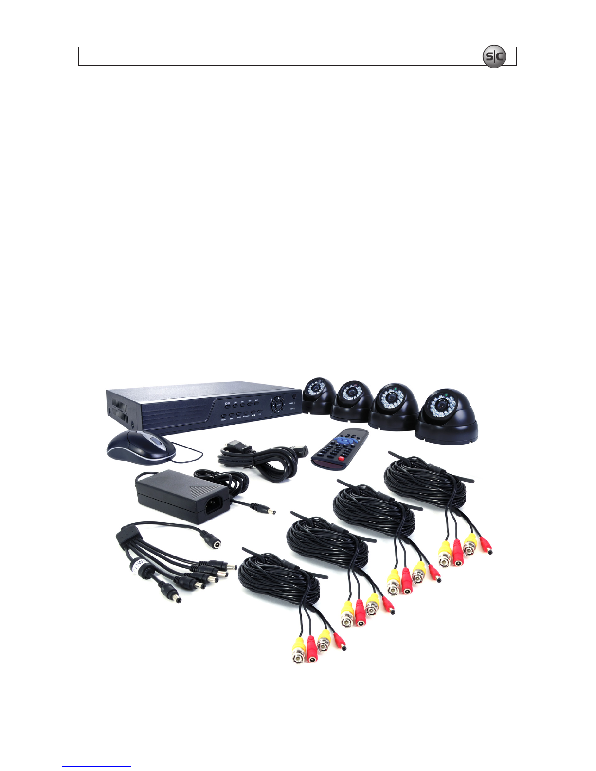
Your system includes:
• 4 channel H.264 networkable DVR w/ 500GB HD and power adapter (SYRF04-KIT)
• 4 – IR dome cameras (CD33-2)
• 4 – 60’ video/power extension cables
• Power adapter with 5-way splitter
• User guides for the DVR, cameras, smartphone applications (on CD), and monitor (if included)
• USB mouse
• LCD Monitor (LCD17-5, with SYRF04LCD only, not shown)
• Mini-CD with smart phone applications
• This manual
Remove the equipment from its packaging and place it on a at, clean surface. Inspect each item. If any
visible damage is present, contact your supplier or Supercircuits for a replacement. Verify that your order
is complete.
Cameras
5-way
Splitter
Mouse
Remote
Control
Video/Power
Extension Cables
DVR
Power
Adapter
SECTION 2: GETTING STARTED: UNPACKING THE EQUIPMENT

4
www.supercircuits.com
SECTION 2: GETTING STARTED: UNPACKING THE EQUIPMENT
What you need
Although each security system installation is different, most require the following items not included with
your system components:
• Tools to install the cameras and route power and video cables
• Fasteners to attach the cameras to the mounting surfaces
• A display device and cabling to connect it to the DVR. The DVR will connect directly to a VGA video
monitor, or to a TV with a BNC to RCA adapter and RCA cable. The display device is usually needed
only for system setup. It can be disconnected when the DVR is networked for access across a LAN
or Internet.
• Uninterruptible power supply (UPS). This device is used to ensure system stability during voltage
surges, sags, and outages. If a UPS is not available, a power strip with strong surge protection is
highly recommended.
54-Camera H.264 Security System Setup Guide
SECTION 3: INSTALLING YOUR SYSTEM
SECTION 3
Installing Your System
3.1 Camera installation
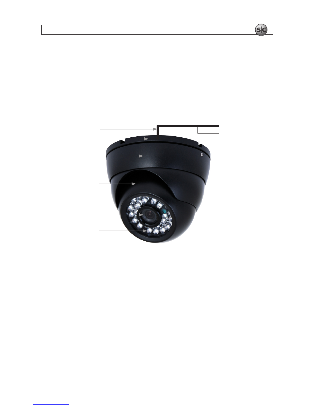
Your CD33-2 camera is a precision instrument that will provide years of quality service when used
properly. Included with each camera is a 60’ video and power cable.
Drop Cable
Video 75 Ohm
12 V DC
Base
Housing Bezel
Turret Style
Camera Housing
Camera Lens
IR LEDs
3.1.1 Camera placement
Plan your camera installation carefully. Identify the locations where cameras will provide the best
coverage, considering:
• Field of view – Cameras must be positioned so they can effectively view the entire area that must
be monitored, and in a location that makes tampering with it difcult.
• Lighting – Direct sunlight shining on the camera lens or bright reections from shiny objects in
the eld of view can diminish video quality and camera performance. Mount the camera in shaded
areas, if possible, or where these inuences can be minimized.
• Ease of installation – Must be able to install the camera at the location, considering mounting
hardware requirements, temperature, dust, moisture, etc.
6
www.supercircuits.com
SECTION 3: INSTALLING YOUR SYSTEM
About weatherproof cameras
Weatherproof cameras can be mounted in any open area, such as on a telephone pole or on the side of a
building. However, for best results, we recommend you mount your cameras in a sheltered area, such as
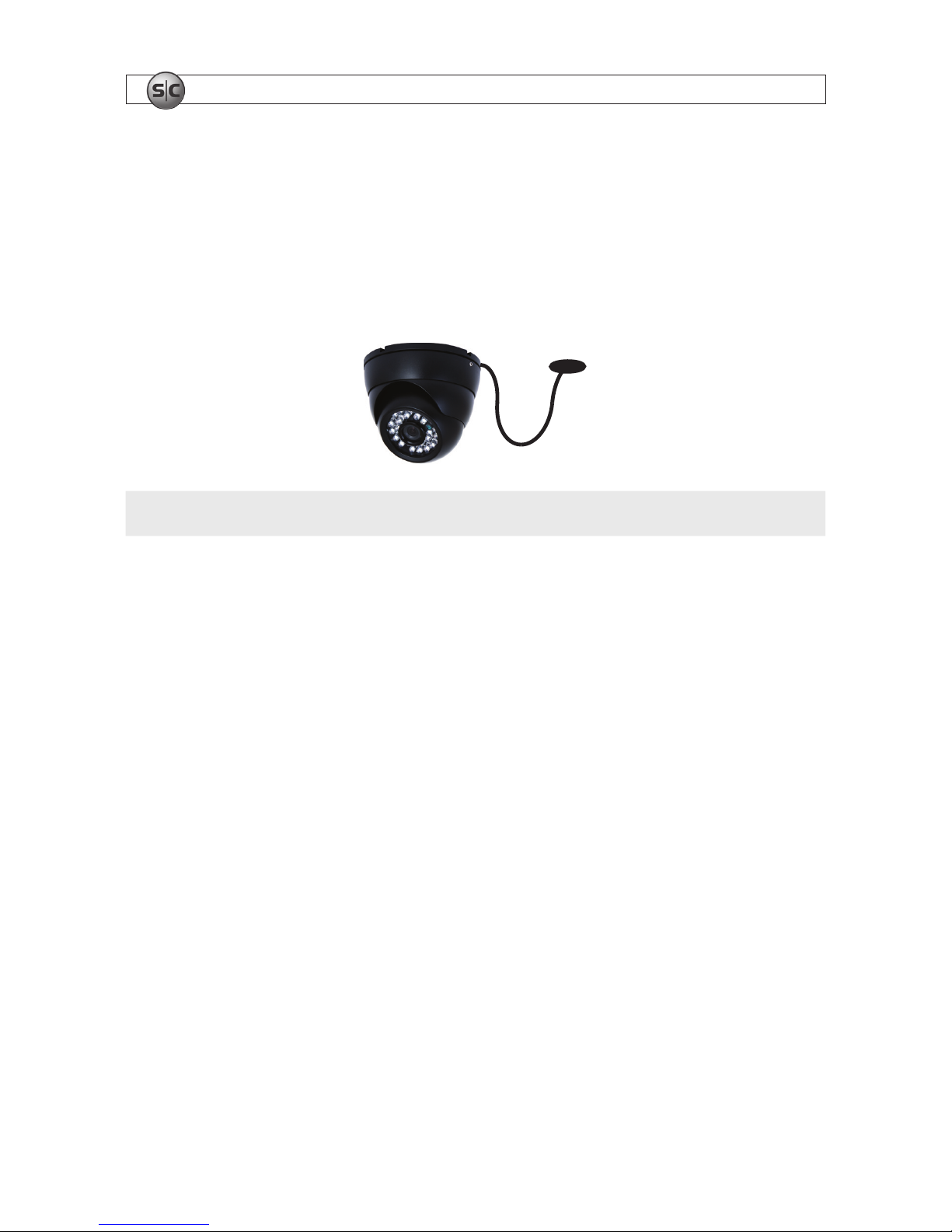
under the eave or roof of a building. Point the camera in the direction you wish to observe. When routing
cable near the camera, allow enough slack to form a U-shaped “drip loop” if it is exposed to moisture or
rain water. A drip loop helps to direct water, that accumulates on the cable, away from the camera.
Drip Loop
Drop
Cable
NOTE
Cable connections are not weatherproof.
Video/power cables can be run almost anywhere, and are frequently routed through attics or above
drop/acoustic ceilings because of the ease of installation. For added security, we recommend you run
your cables in areas with limited access to prevent tampering. Avoid running the cable near high voltage
appliances such as uorescent lighting. Electrical noise and magnetic elds produced by these devices
may affect video signal quality.
A 60’ video/power cable is shipped with every camera in your system. 100’ and custom-length cables
are also available from Supercircuits.
3.1.2 Mounting
1. Separate the base from the rest of the camera assembly by unscrewing the housing bezel.
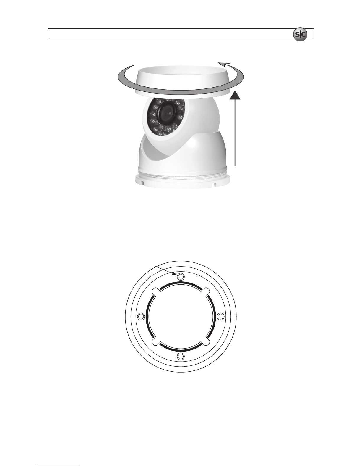
74-Camera H.264 Security System Setup Guide
SECTION 3: INSTALLING YOUR SYSTEM
Removal of housing bezel
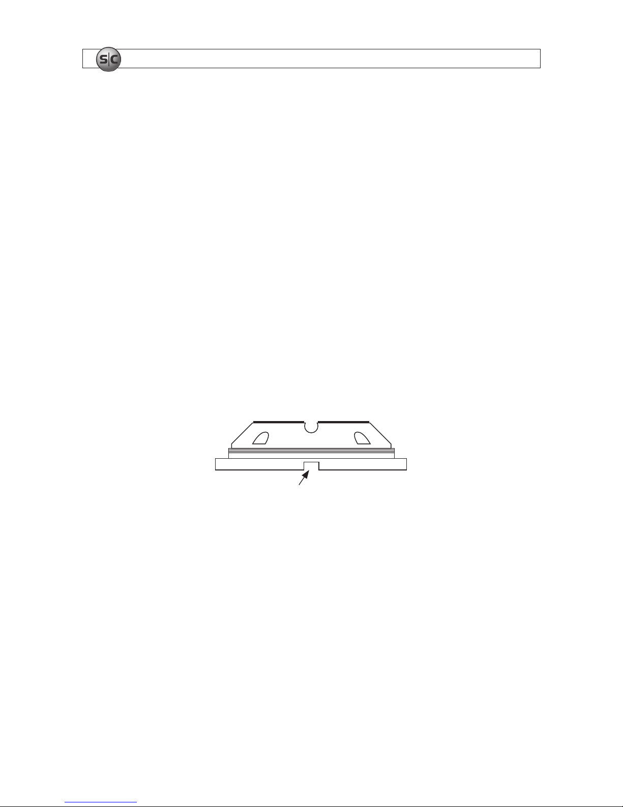
2. Determine where the camera will be mounted.
3. Using the base as a template, mark the location of the four mounting screw holes.
Mounting Screw Hole
Camera base
8
www.supercircuits.com
SECTION 3: INSTALLING YOUR SYSTEM
4. Drill mounting screw holes into the mounting surface.
a. If the mounting surface is a soft material, such as a drywall, use a 3/16” bit to drill the
mounting holes. Use a hammer to tap the wall inserts provided into each hole until they are
ush with the surface.
OR
b. If the mounting surface is a very soft material, such as ceiling tile, place a wood block behind
the tile. Screws longer than 1” may be required. Drill holes for the mounting screws through the
surface and into the wood block.
OR
c. If mounting the camera on a harder surface, such as wood, drill the mounting screw holes with
a 3/32” bit.
5. Determine the cable routing. If the cable is to be routed through a hole in the mounting location
within the coverage of the base, perform the following steps. If the cable will be routed through a
cable guide in the base, skip to step 9.
Cable Guide in Base
6. Drill a 3/4” hole through the mounting surface at the center of the base.
7. Use a #2 Phillips screwdriver to mount the base with the provided screws.
8. With the camera in the camera housing, route the drop cable through the 3/4” hole until the
camera housing is tted onto the base. Place the housing bezel over the camera housing and screw
it onto the base until the camera and camera housing are held in place. Skip to step 12.
9. Set the camera on the base with the camera cable pressed into one of the cable guides of the base.
Allow some slack in the cable within the base to allow for camera positioning later.
10. Use a #2 Phillips screwdriver to mount the base with the provided screws.
94-Camera H.264 Security System Setup Guide
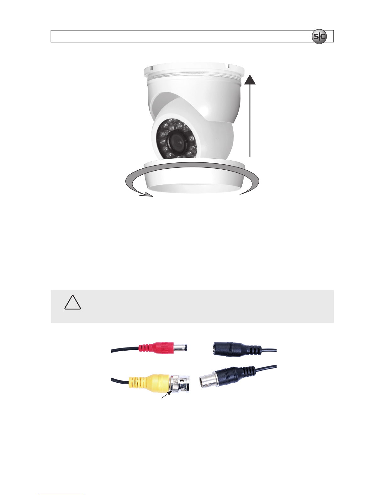
SECTION 3: INSTALLING YOUR SYSTEM
Tighten housing bezel
11. Without allowing the camera to hang by the drop cable, place the camera housing with the housing
bezel over the camera and t it onto the base. Screw the housing bezel onto the base until the
camera and camera housing are held in place.
12. Attach the BNC video/power cable to the camera cable as required.
CAUTION
Notice that power connectors on the BNC video/power cable are different at each end!
Extension
Cable
Camera
Drop Cable
Power
Video
Lock Ring
Cable attachment
10
www.supercircuits.com
SECTION 3: INSTALLING YOUR SYSTEM
3.2 Install and setup the monitor (SYRF04LCD systems
only)
The SYRF04LCD system includes the LCD17-5 monitor. If you did not purchase this monitor, setup your
system monitor at this time, then continue at subsection 3.3.
1. Find the monitor assembly and base. Use the screw provided to attach the base to the monitor
support bracket. The screw may be attached to the underside of the monitor support bracket or in
the base.
Base
Support
Bracket
Screw
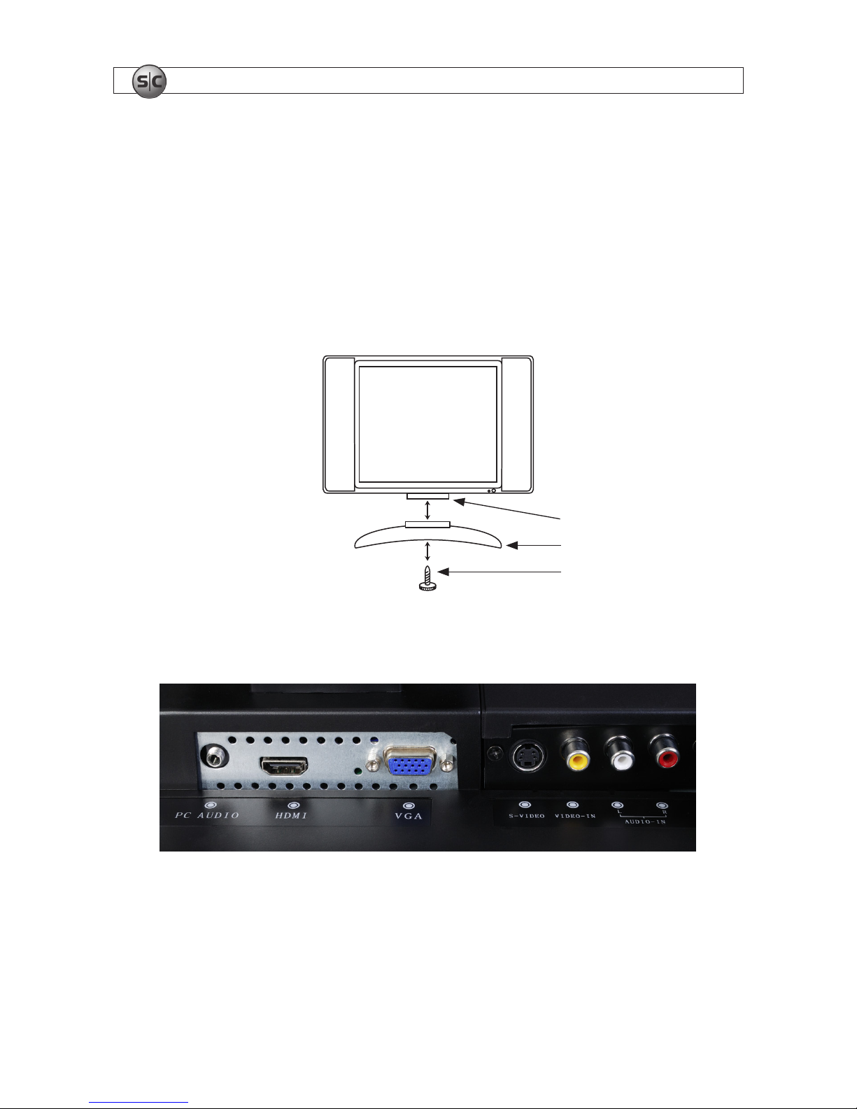
2. Attach the VGA cable provided with the monitor to the VGA input connector on the lower back side
of the monitor.
Inputs on the lower back side of monitor
3. Attach the other end of the VGA cable to the Main OUT (VGA) connector on the back of the DVR.
4. Attach the power cable to the monitor and plug it into a grounded power outlet.
114-Camera H.264 Security System Setup Guide
SECTION 3: INSTALLING YOUR SYSTEM
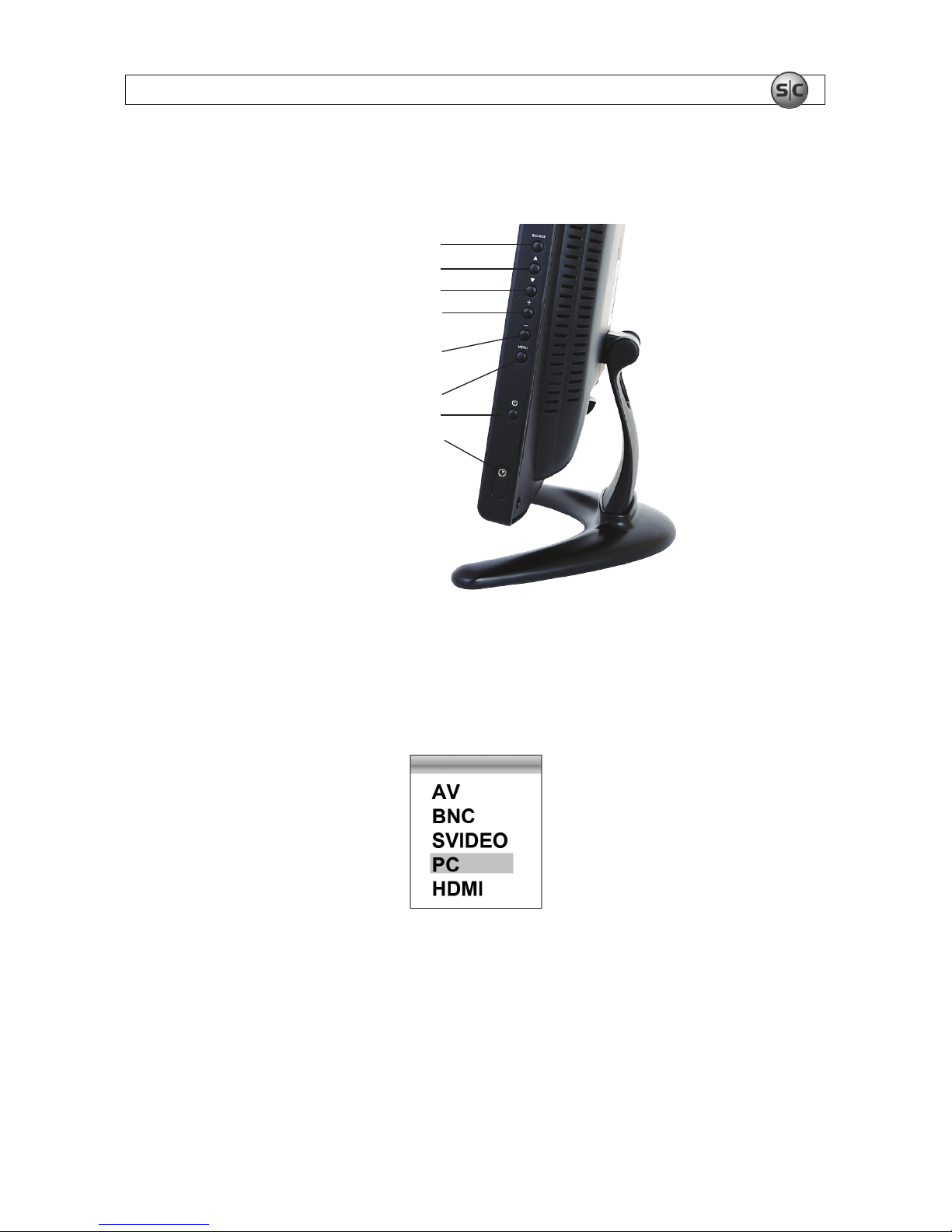
5. Press the Power button to power on the monitor. The Power button is located in the control panel
on the right side of the monitor.
SOURCE
Move up in menu
Move down in menu
Move right in menu
or volume up
Move left in menu
or volume down
MENU (open/close)
Power
Audio output
Monitor control panel
6. Press the SOURCE button on the monitor control panel to open the video source menu. Use the p
and q buttons on the control panel to highlight PC, and then press the MENU button to select that
interface. An indication will appear on the screen conrming your selection.
7. Power off the monitor using the Power button on the control panel.
12
www.supercircuits.com
SECTION 3: INSTALLING YOUR SYSTEM
3.3 DVR installation
Your DVR is an advanced network video recorder that includes many features not covered in this guide.
Please refer to the DVR User Manual for additional information.
3.3.1 Controls and connectors
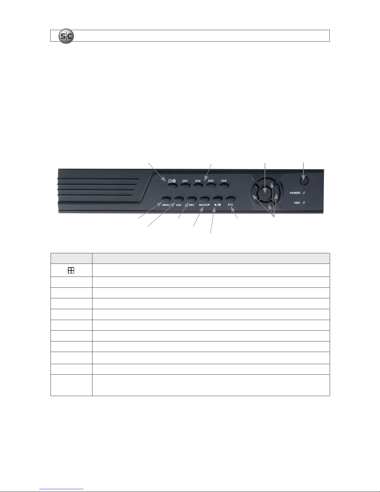
DVR Front Panel
Single/Multi Camera
Display Toggle
tqpu Menu
Navigation
Buttons
Enter
Escape
Menu
Play/Pause
Record
CH1 .. CH4
Camera Select
Infrared
Sensor
Pan/Tilt/Zoom
Control
Backup
Button Usage
o /
Toggles between single camera, multi-camera display.
CH1 .. CH4 Used to select the camera on channel 1, 2, 3, or 4.
Enter Press to conrm a menu choice.
Infrared Sensor Sensor for the remote control.
MENU Opens the main menu window
ESC Press to exit any active window.
REC Use to start and stop manual recording.
BACKUP Opens a video search and playback menu.
u/II
When a recorded le is selected, press this button to play. then press it again to pause playback.
PTZ Used for pan/tilt /zoom control of cameras with this feature.
t q p u
Use these buttons to navigate through the menu system. Generally, use the t u buttons to move to
selection boxes, and use the q p to select submenu parameters.
134-Camera H.264 Security System Setup Guide
SECTION 3: INSTALLING YOUR SYSTEM
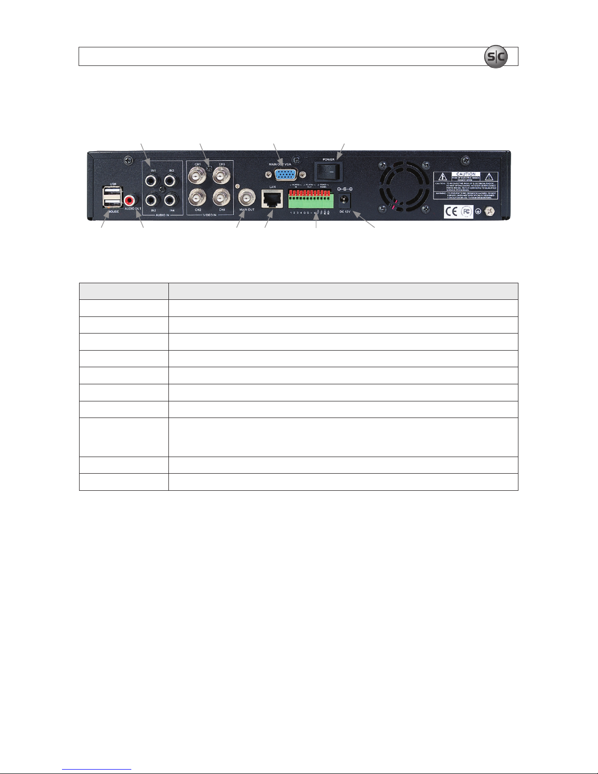
DVR Backpanel
IN1 - IN4
Audio In
CH1 - CH4
Video In
Audio Out LAN Main Out
(BNC)
Power
Alarm In/Out,
RS422/RS485
Connections
Main Out
(VGA)
USB Power DC 12V
Connector Usage
USB - MOUSE Use these USB ports to connect a mouse, or a backup device such as a ash drive or DVD recorder.
AUDIO OUT Audio output from channel AUDIO IN channels 1, 2, 3, or 4.
IN1 .. IN4 AUDIO IN RCA audio input to audio channels 1, 2, 3, and 4.
CH1 .. CH4 VIDEO IN BNC video input to video channels 1, 2, 3, and 4.
MAIN OUT
BNC composite video output to display device (75Ω, 1V p-p).
MAIN OUT VGA Standard VGA output to a display device, such as a computer monitor.
LAN Standard RJ45 Ethernet 10BaseT, 100BaseT port with auto detect.
ALARM IN, ALARM
OUT, RS422 RS485
Use these connectors to attach external sensor devices, alarm reporting devices, and devices with
an RS422 or RS485 control interface, such as PTZ cameras. See the DVR Uer Manual for more
information.
DC 12V Connect to 12 VDC power adapter.
POWER Power switch to turn the unit on and off.
3.3.2 DVR placement
Your monitoring and recording equipment is central to constant surveillance and the reliable capture
of video evidence. Supercircuits strongly suggests that it be installed in a secure location with access
limited to authorized personnel.
DVRs generate heat and should be placed in a ventilated area. A high temperature environment will
reduce the life span and reliability of the equipment. Additionally, the DVR is not weatherproof, so avoid
exposure to liquids and excessive dust. Do not place objects along the sides or behind the DVR that will
block airow through the unit.
14
www.supercircuits.com
14
Uninterruptible power supplies
It is strongly suggested that power to the system be routed through an uninterruptible power supply
(UPS). These devices will keep your security system running through most power outages, in addition
to providing excellent surge and sag protection. The UPS should support your video recorder and all
cameras to ensure normal operation during abnormal power conditions.
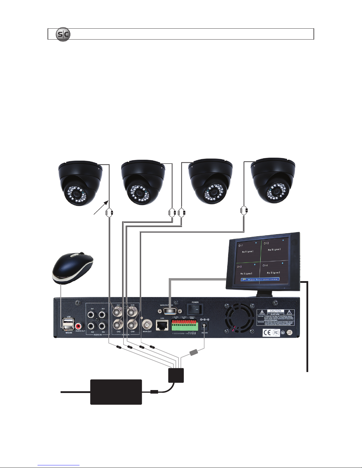
3.4 Connecting the system together
All connections to the DVR are made on the back of the unit.
Video/Power
Cables
VGA Cable
5-Way
Power
Splitter
To 120 VAC
Monitor Power
Power Adapter
Mouse
Camera
Drop Cable
To UPS/
120 VAC
Interconnection Diagram
SECTION 3: INSTALLING YOUR SYSTEM
154-Camera H.264 Security System Setup Guide
SECTION 3: INSTALLING YOUR SYSTEM
15
1. Connect the system mouse to the USB connector labeled MOUSE.
2. Connect the camera video signal cables (BNC connectors) to the VIDEO IN CH1 to CH4 connectors
3. Connect a display device to the DVR. If using a VGA monitor for a display, connect it to the VGA
MAIN OUT connector. If using the BNC MAIN OUT connector to drive a display such as a TV, attach
the appropriate cables between the BNC MAIN OUT and your display device.
4. Connect the 5-way power splitter to the power adapter, then:
a. Connect the lead marked DVR POWER to the DC 12V connector on the DVR backpanel.
Ensure that the POWER switch on the DVR is off.
b. Connect the other leads of the splitter to the mating connectors on the video/power extension
cables routed to the cameras.
5. Connect the power cord to the power adapter and plug it into a standard grounded 120 VAC power
source through a UPS or surge protector.
6. Power on your system monitor.
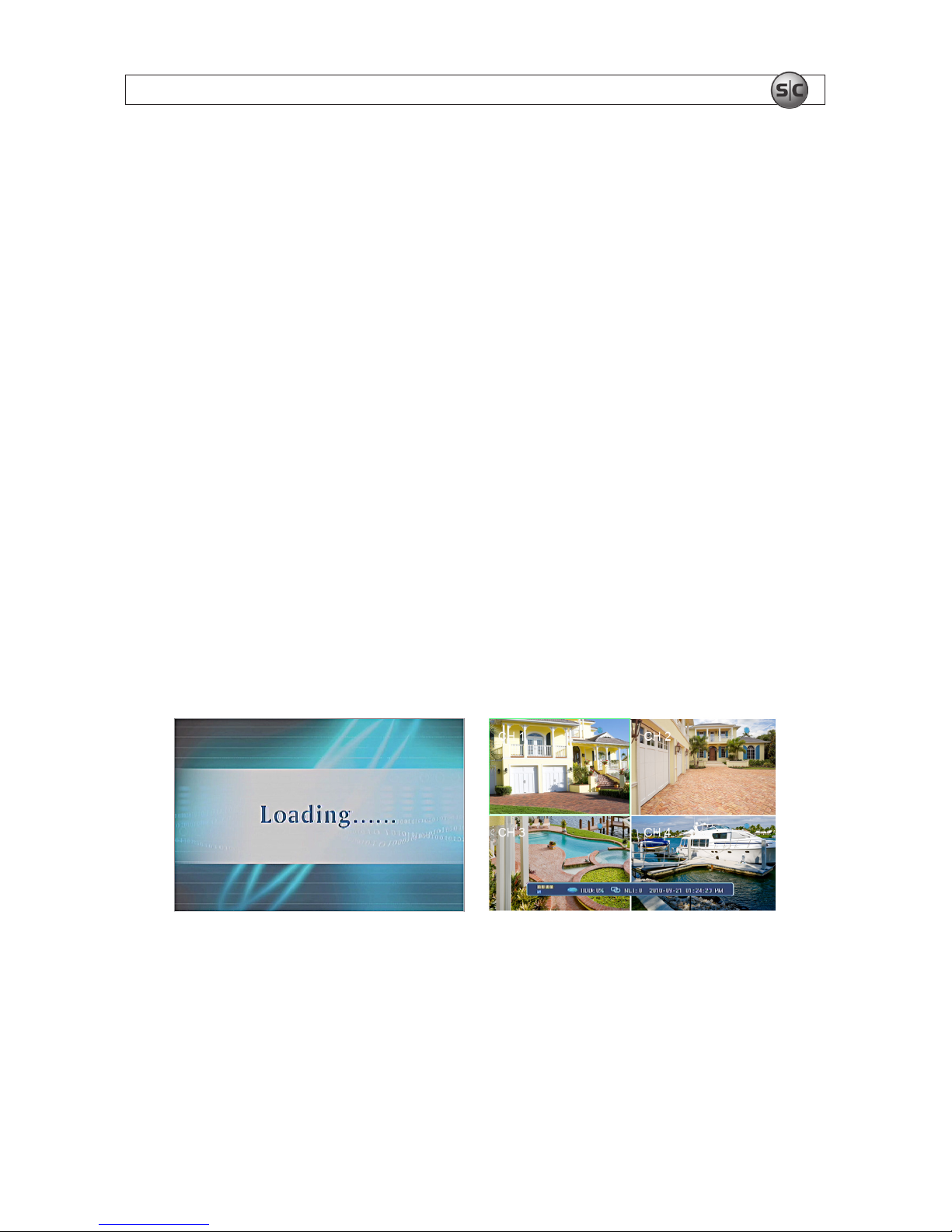
7. Power on the DVR using the POWER switch on the backpanel. A startup “Loading” screen will
appear on the display. After a few seconds, the screen will change to the camera view screen.
..
Note: The images you see from your cameras may be different from those shown here.
3.5 Aiming the Camera
1. Loosen the housing bezel until the housing can be rotated on the base.
 Loading...