

Page 1
H.264 Video Server
Quick Guide
S20712ch /S40714ch
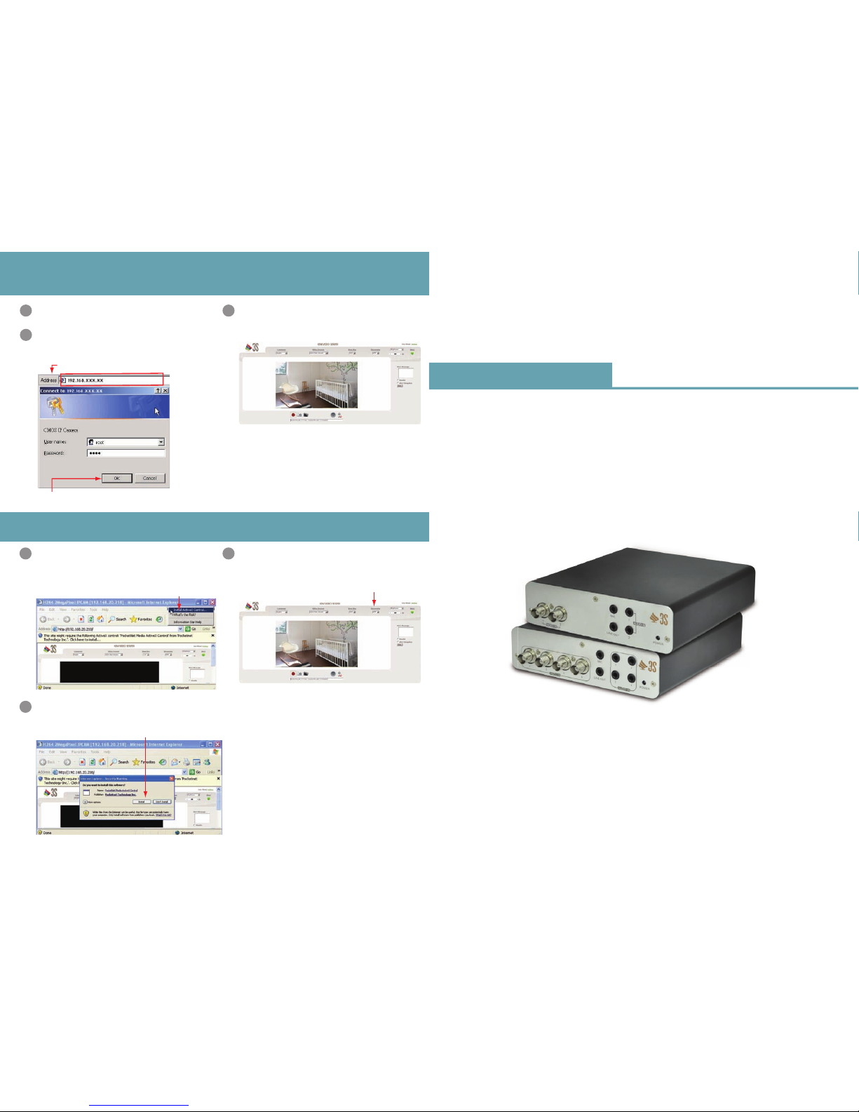
Enter the Main Page
Step
4
Install Internet Explorer Active X Controller
Step
5
Open a new Internet Explorer window.
Start
1
Enter the new IP address and key in the username
“root” and password “root”.
Enter the IP address and login
2
●
When the login screen appears, key in root in the
User Name and Password fields. Click OK.
●
Enter the IP address that you have just set.
You can enter the control screen when the username and
password are confirmed.
Enter the control screen
3
When the username and password are confirmed, a
control setup screen pops up under the IE address bar.
Click “Install ActiveX Control” to install the controls.
Install ActiveX
1
●
Click Install ActiveX Control
RMIM-01G06003 Ver:20
When ActiveX Control is installed successfully, you can
see the camera image and interface.
Camera operation and interface
3
●
Select the HTTP mode if the image is disabled.
●
Click Install
The ActiveX Control is named ActiveX Control.
This software is well certified. You can use it without any
doubts on its validity.
The security warning screen aps. Click Install.
2
- Page 3 -
Page 2
1
91011121314151617181920
234567 8 RTRX+
-
DC 12V
ALARM IN
DC OUT RS485
ALARM OUT
SD CARD
LAN
RESET
1. Make sure the analong camera is use the BNC connectors.
2. Please refer to user manual for more detailed explanation of the
hardware installation.
3. Where no switch hub is available, you can search and set up the
camera using the network peering approach. However, you may need a
jumper and need to change the LAN configuration on your PC for this
purpose. It is recommended to request a qualified engineer for the
connection or execute the network peering referring to the user's
manual .
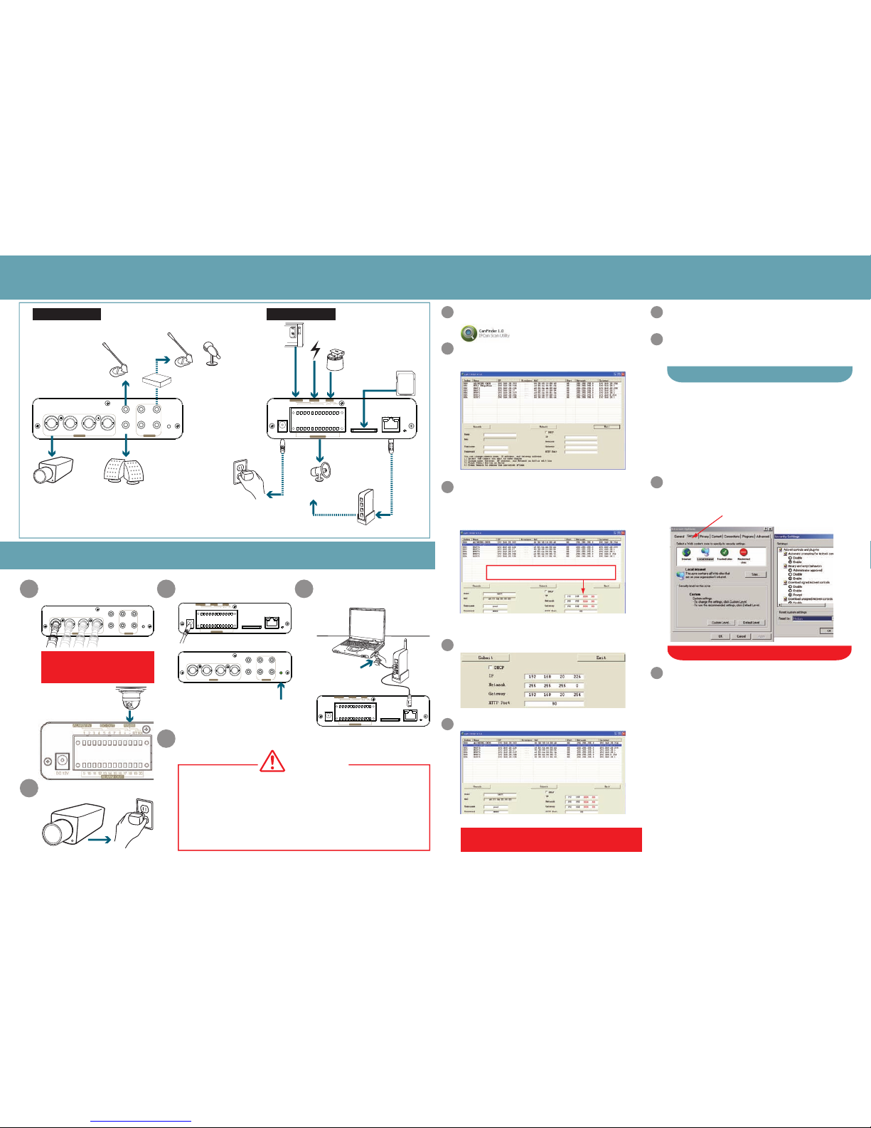
Connection diagram
Step1
1 4
5
3
2
Camera settings
Step
2
Change the Internet Explorer
settings
Step
3
●
Click Search to find the IP CAM on the LAN.
Note:
If this software cannot run successfully, check that it is not
blocked by an anti-virus software or firewall.
Execute the IP Finder.exe file from the supplied CD.
Start
1
Search for the product from your LAN. The default IP
setting 192.168.0.20 appears on the screen.
Find the camera (Search)
2
When you find the camera, click it and the settings
appear on the right side. You can change the settings
for the new network environment as you need.
Changing the IP address and related
settings for the network environment
3
Submit data (Submit)
4
●
Click Submit to apply the new settings.
Confirmation
5
●
Click Exit to quit, after all chages have been confirmed.
Open the IE browser
↓
Tools
↓
Internet Options
↓
Security
↓
Custom Level
Steps
Note: This product supports IE 6.0 or above.
●
Check that the security level is Level II.
Bring Up Your IE browser.
Start
1
Make sure that Level II, the commonly used default
security level, is set for the security.
Check
2
Make sure that Level II, the commonly used default security
level, is set for the security.
Select “medium” for security
3
Click OK to quit.
OK
4
●
Enter the settings for the new network
environment you need.
- Page 1 - - Page 2 -
VIDEO IN
123
MIC
LINE OUT POWER
4
43
12
AUDIO IN
• Video In
• Speaker
• Power
• SD Card
• PT Controller
• Direct Current Power
• Infrared Inductor
• MIC
• MIC
Front Pannel Rear Pannel
• Amplifier
• HUB
• WAN Internet
• High dB
alarm
Alarm Output
Connect the video server to the switch hub and analog camera
VIDEO IN
123
MIC
LINE OUT POWER
4
43
12
AUDIO IN
Connect the Video source to
Video IN.
Note:
Please connect RS-485 to the video
server if your analog camera supports
PTZ function.
Power on the analog camera.
Check the indicator lamp of POWER
after power on the video server.
Connect the video server and PC
to the switch hub.
Connection settings is completed.
VIDEO IN
123
MIC
LINE OUT POWER
4
43
12
AUDIO IN
• The indicator lamp of POWER will
be green when power on.
Attention
• You have to enter a new settings in the IP Netmask and
Gateway fields and keep the settings in other fields
unchanged.
or
1
91011121314151617181920
2345 678 RTRX+
-
DC 12V
ALARM IN
DC OUT RS485
ALARM OUT
SD CARD
LAN
RESET
1
91011121314151617181920
234567 8 RTRX+
-
DC 12V
ALARM IN
DC OUT RS485
ALARM OUT
SD CARD
LAN
RESET
 Loading...