

Super Circuits PC88WR Operation Manuals
BULLET BLACK & WHITE CCD CAMERA
OPER AT I ON M A N UA L
KEY F E ATURES
Th an k yo u for choo sing our hig h qu alit y ca mera . Be fore att empt ing to co nn ec t or o pera te,
pl ea se r ea d an d fo llow the se i nstr ucti ons.
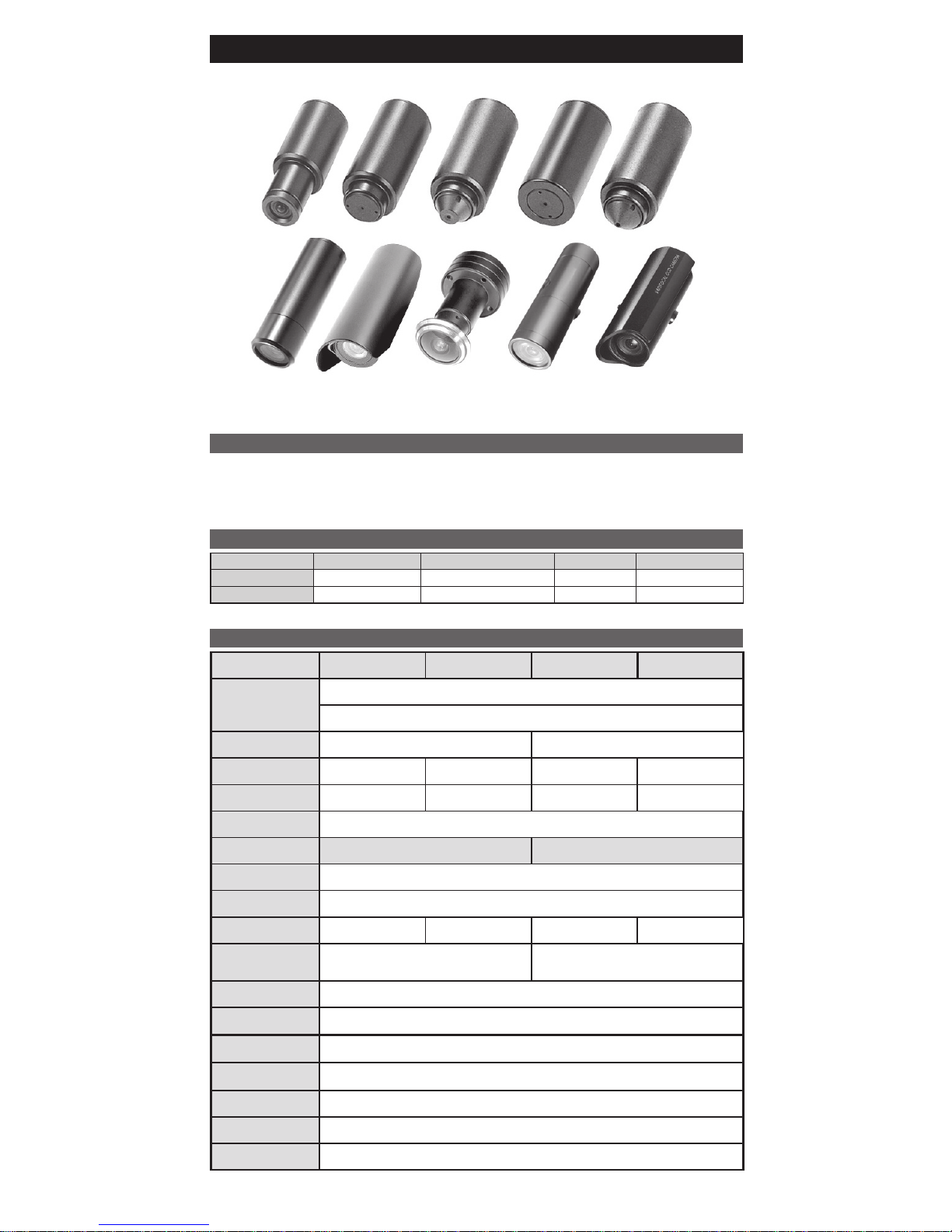
The se CCD video cameras employ a SONY 1/3” CCD solid -state imaging device which pro vide su perior
performance. These cameras can be easily in mostly indoor locations along with its very low current consumption
of 80mA or less. These cameras are not only easy to install but achieve an excellent reliability record.
ACCESS O R I E S F URN I S H E D
SPEC I F I C ATION S
Acces s o r i e s DIY c a b l e Mount i n g B r a c k e t Screw Manua l
Q'ty - 1 3 1
Optio n 1 - - -
Face Plat e : Point at the CC D wi thout obstruc ti on of light from an y other material.
Signal Format EIA CCIR EIA CCIR
Image Device
1/3" Sony Super HAD CCD
1/3" Sony Exview HAD CCD
Scanning Frequency
H:15.734[KHz], V:59.94[Hz]
H:15.625[KHz], V:50[Hz]
Total Pixels
537(H) x 505(V)
537(H) x 597(V) 811(H) x 508(V) 795(H) x 596(V)
Effective Pixels 510(H)x492(H) 500(H)x582(H) 811(H)x508(H) 795(H)x596(H)
Scanning System 2 : 1 Interlace
H.Resolution 420TV Lines 600TV Lines
S/N Ratio More than 50dB(AGC Off)
Gamma
γ=
0.45
Electronic Shutter 1/60 ~ 1/100,000sec 1/50 ~ 1/100,000sec 1/60 ~ 1/100,000sec 1/50 ~ 1/100,000sec
Min.Illumination
0.5 Lux@F2.0/30IRE
Exview 0.0003Lux/FacePlate
0.1 Lux@F2.0/30IRE
Exview 0.003Lux/FacePlate
Gamma
γ=
0.45
Video Output Composite 1[Vp-p] 75[Ω] unbalanced
Operating Temperature -10℃ ~ +50
℃
Storage Temperature -20℃ ~ +60
℃
Power Consumption DC 12V (±10%) 80mA or Less
Option 19Φ(mm), 23Φ(mm)
Lens Option Board Lens, Pinhole Lens, Door View Lens, Varifocal Lens
This device complies with Part 15 of the FCC Rules.
Operation is subject to the following two conditions;
1. This device may not cause harmful interference.
2. This device must accept any interference received, including interference that may cause undesired operation.
This equipment has been tested and found to comply with limits for a Class B digital device, pursuant
to part 15 of the FCC Rules. These limits are designed to provide reasnoable protection against
harmful interference in a residential installation.
This equipment generates, uses, and can radiate radio communications.
However, there is no guarantree that interference will not occur in a particular installation. If this
equipment off and on, the user is encouraged to try to correct the interference by one or more of the
following measures:
Note -
• Re or ie nt o r re lo cate the rec eivi ng a nten a.
• In cr ea se t he s ep arat ion betw een the equi pmen t an d re ceiv er.
• Co nn ec t th e eq ui pmen t in to a n ou tlet on a ci rcui t di ffe rent fro m th at t o
wh ic e th e re ce iv er is conn ecte d.
• Co ns ul t th e de al er o r an exp erie nced rad io / tv tech nici an f or h elf .
An y ch an ge s or m od ific atio ns i n co nstr ucti on o f th is d evie s wh ich are n ot
ex pr es sl y ap pr ov ed by the part y re spon sibl e fo r co mpli ance cou ld v oid t he
us er 's a ut ho ri ty t o op erat e th e eq uipm ent.
Caut i o n -
1. A re gula ted D C1 2V 3 00mA p ow er s up ply is r eco mm en de d for use wit h th is c amer a
fo r th e be st p ict ur e and the most st ab le ope rati on.
An unr egul ate d po we r supp ly c an ca us e da mage to the c am er a.
Wh en u nreg ulat ed po we r su pply is app li ed , pr oduc t wa rra nt y will be
ou t of sub ject .
2. I t is r ecom mend ed th at the cam era is us ed wit h a moni tor t ha t ha s a CCT V qu al it y
75 vid eo i mped anc e le vel.
If you r mo nito r i s sw itch ed t o hi gh im pe danc e th en p lea se a djus t ac cor di ng ly.
3. D o not atte mpt to di sa ssmb le t he c ame ra t o ga in a cces s t o th e in tern al co np on et s.
Re fer serv icin g t o yo ur d eale r.
4. N ev er f ace the cam er a towa rds the sun o r any brig ht o r r ef le ctiv e li ght , wh ic h may
ca use smea r on th e pi ctur e an d po ssi bl e dama ge t o th e C CD .
5. D o not remo ve t he se ri al s tick er f or th e warr anty ser vic e.
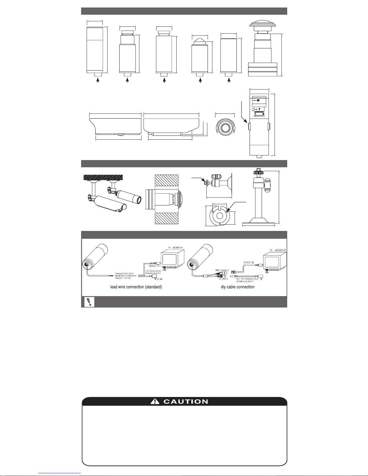
DIME N S I O N S
CAME R A M O U N TIN G P O S I T ION
Unit : mm
When y o u i n s t a l l the ca m e r a , p l e a s e glue u p t h e e n d o f cable t o
keep i t s t a b l e i n order t o p r o t e c t the cam e r a f r o m t h e humid i t y p r o b l e m s.
CONN E C T I O N
54.4
45
45
37
40.8
50.5
Mounting Hole
(1/4"-20UNC)
Mounting Hole
(1/4"-20UNC)
Mounting Hole
(1/4"-20UNC)
Mounting Hole
(1/4"-20UNC)
Mounting Hole
(1/4"-20UNC)
Φ
19
Φ
19
Φ
19
Φ
19
Φ
19
110 75.5
130 95
Φ
32.4
Φ
23
Φ
26
Φ
37
111
Mounting Hole
(1/4"-20UNC)
Φ
60
37~70
500 or 700
Mounting Hole
(1/4"-20UNC)
40
28.6
24.8
97
3 -
Φ
3.2
 Loading...