

Page 1
50 Ft IR True LPR Weatherproof Camera
User Manual
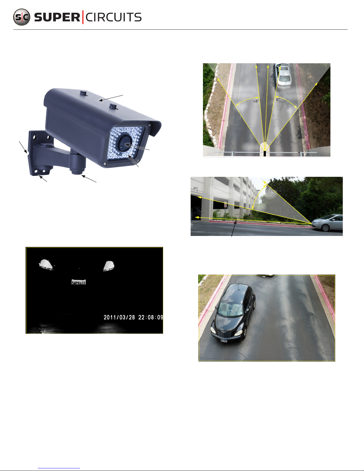
The Supercircuit s PC813IR LPR (License Plate Recognit ion) c amera is ideal for isolating images of license
plates of cars moving through an entr y point, in slow trac, or when st ationary. This camera provide a
usable license plate image, day or night.
Sun Shield
Cable
Guide
Horizon tal range: Horizont ally, the c amera must be positioned between 8° and 35° left or right of
the centerline of the vehicle.
Direction of
Camera
Sector with
best view
+35°
+8°
0°
Sector with
-8°
best view
-35°
Mounting Plate
Gimbal Set Screw
Impor tant features i nclude:
• 600 lines of resolution
• 9-22 mm lens
• 50 ft IR range
• Captures license plates on vehicles moving up to 30 mph
• Concealed bracket
• 4.88” (w) x 12.8” (l) x 7.72” (h)
Lens
LED Array
Camera
Vertic al range: Vertically, the camera must be positioned bet ween 10° and 38° of the plane the
vehicle is traveling in.
Position Camera in This
Sector for Best View
Direction of Travel
Field of vi ew: the camera field of view should be adjuste d to include the entire lane width where the
38°
10°
vehicle will travel. These adjustment s are made by aiming the camera, set ting the zoom (tele-wide),
and focus. Se e step 2.
LPR Camera Image of a Car at Night
What’s in th e box
• Mounting template
• 4 screws with wall insert s
• Hex wrench
• Power cable adapter
• This instruction shee t
Camera Placement
To capture the image of a license plate, the vehicle cannot be tr aveling more than 30 mph, and the camera
must be positioned within a specic range. Also, since some jurisdictions only require license plates to b e
displayed on the back of the vehicle (for inst ance, on motorcycles in most locations) the camera should b e
positioned to see them. The position of the cam era should meet the following four criteria:
Horizon tal distance: The camera must b e placed within 50 feet of the target license plate.
www.supercircuits.com
1
Field of View - 811 x 508 pi xels
Step 1. Installing the camera
When installing the camera, the vide o and power drop cables can be routed through the mount ing
surface behind the mounting plate (most secure), or through cable guides on the side s of the mounting
plate.
1. Find the optimal position for the camera, obser ving the Camera Posi tion guidelines above.
2. Determine and acquire fasteners adequate to att ach the camera to the mounting sur face. The screws
and wall insert s are provided with your camera work well with many sur face types.
PC813IR_CQ
Page 2
3. Apply the mounting template to the mounting surface. Mark the location of t he holes for the
fasteners.
4. Attach the camera to the mounting surface wi th 4 fasteners.
5. Connect the drop cable BNC conne ctor to a mating connector on a video extension cable. Connec t
the other end of the e xtension cable to a video recorder or monitor.
NOTE
Drop cable video and power connectors a re not waterproof.
6. Connect the c amera power drop cable to a power ex tension cable. The polarity of t he power drop
cable is shown in the f ollowing representation. An adapter f or a non-connectorized power source is
provided with the camera.
7. Connect the other end of the power e xtension cable to a 12 VDC power source. Verif y that an image
from the camera appears on the monitor.
Step 2. Camera setup
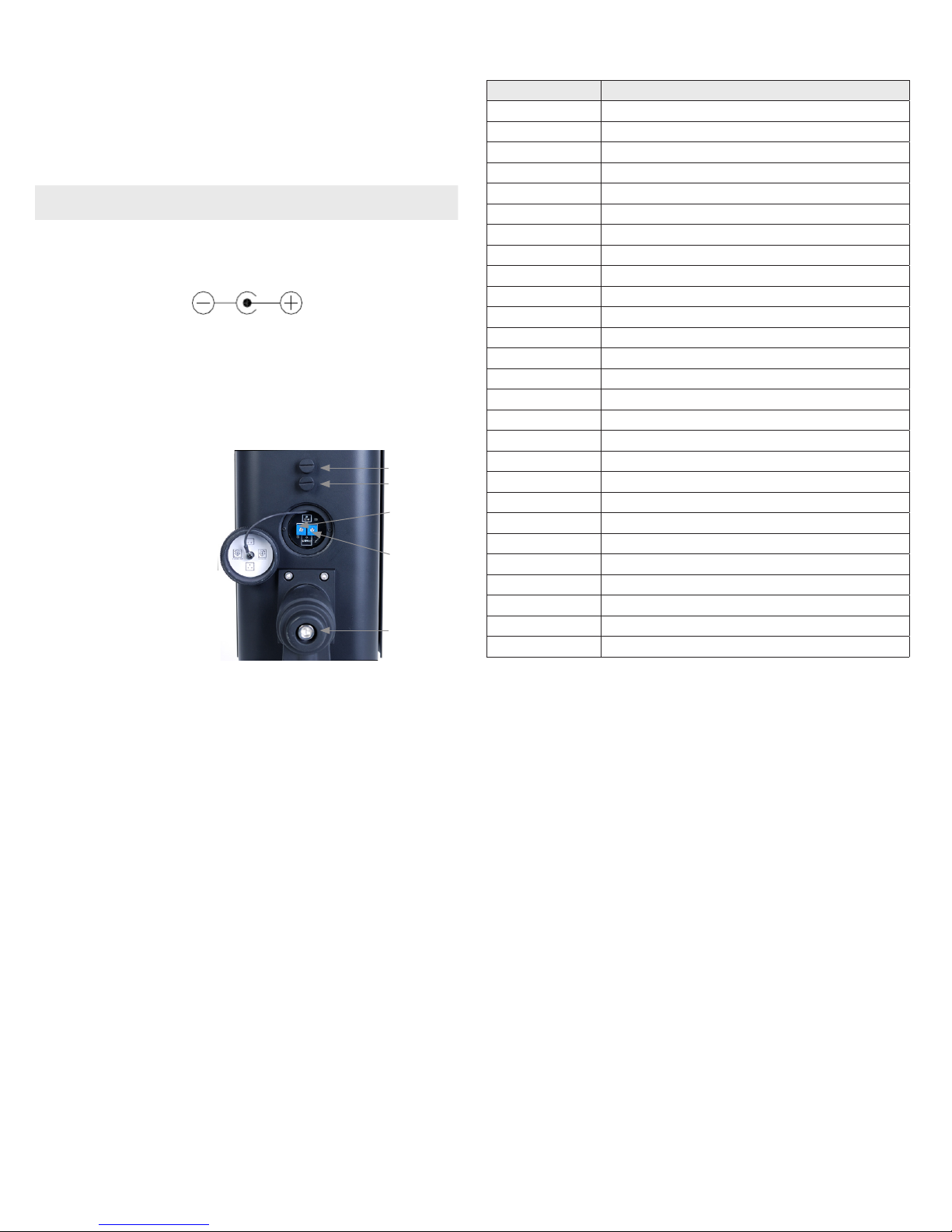
All setup adjustments are made on t he underside of the camera body.
8. While observing video from the
camera, loosen t he gimbal set screw
until the camera b ody can move freely.
9. Point the camera at the center of the
eld of view, then tighten the set
screw.
Focus
Tele-Wide
IR LED
Intensity Pot.
IR LED
Working
Time Pot.
10. Set the Tele-Wide adjust ment to ll the
image with the be st eld of view.
11. Set the focus adjustment to shar pen
the image.
Gimbal
Set Screw
Table1.Specication s
Item Speci cation
IP rating IP66
Filter Five-la yer lter
Image Sen sor 1/3” Hi-res olution Color S ony® CCD
Pixels 811 (H) x 508 (V)
Horizon tal Resolut ion 600 TV L
IR LED 80-LE D IR array
Vertica l frequenc y 60 Hz
Horizon tal Frequenc y 15.734 KH z
Clock Fre quency 28.636 MHz z
Scannin g System 2:1 Interlace
S / N Ratio ≥ 50 dB
Elect ronic Shutte r Fixed
White Bal ance Auto trac king
Back Lig ht Compensati on ON
Auto Gain Con trol ON
Gamma 0.45
Video Ou tput 1 V p-p, 75Ω
Lens 9 - 22 mm vari- focal auto- Iris lens
Viewing a ngle Diagona l: 21° / horizontal: 17° ver tical:13°
Power Suppl y 12 VDC ± 10%
Current Co nsumption 200mA
Available IR D istance 6.56 f t~ 49.18 ft (2 m~ 15 m)
Dimensio n 9.92” x 7.30 ” x 4.13 ” (252 mm x 185.5 mm x 105 mm)
Weight 4.32 lbs (1960 g)
Storage Temp erature -22° F ~ +140°F (-30°C ~ + 60°C)
Operat ing Temperature -22°F ~ +104°F (-30° C ~ +40° C)
Capture t he license plate Up to vehicle s traveling at th e speed of 30 mph
12. While viewing a license plate under the darkes t conditions, remove the cap on the underside of the
camera. Then:
a. Adjust the IR LED Intensity potentiometer to produce the best image for the normal distance
of the vehicle from t he camera. Increase the level for more distant vehicles.
b. Adjust the IR LED Working Time potentiome ter for IR use to begin at a specic light ing level.
For example, you can adjust this potent iometer to also use IR during bright conditions, such
as daylight.
c. Reinstall the cap.
www.supercircuits.com
2
© 2011 Supercircuits, Inc. All rights reserved.
 Loading...