

Page 1

Color CCD Box Camera
User Manual
Products: PC33C5G, PC33C5G-RTI, PC33C5G-RTIA,
PC153C5G, PC153C5G-RTI, PC153C5G-RTIA
Camera With Optional Lens
Please read this manual before installing and using this camera and always follow instructions for proper use.
Save this manual away for future reference.
PC33C5G_PC153C5G_CM
5/12/11
Page 2

ii
www.supercircuits.com
LEGAL NOTICE
Supercircuits products are designed to meet safety and performance
standards with the use of specic Supercircuits authorized accessories.
Supercircuits disclaims liability associated with the use of non-Supercircuits
authorized accessories.
The recording, transmission, or broadcast of any person’s voice without their
consent or a court order is strictly prohibited by law.
Supercircuits makes no representations concerning the legality of certain
product applications such as the making, transmission, or recording of video
and/or audio signals of others without their knowledge and/or consent. We
encourage you to check and comply with all applicable local, state, and federal
laws and regulations before engaging in any form of surveillance or any
transmission of radio frequencies.
Other trademarks and trade names may be used in this document to refer
to either the entities claiming the marks and names or their products.
Supercircuits, Inc. disclaims any proprietary interest in trademarks and trade
names other than its own.
No part of this document may be reproduced or distributed in any form or by
any means without the express written permission of Supercircuits, Inc.
© 2011 Supercircuits, Inc. All rights reserved.
11000 N. Mopac Expressway, Building 300, Austin, TX 78759
Sales/Support: 1.800.335.9777 | Fax: 1.866.936.7257
Page 3

iii
Color Box Camera User Manual
PRECAUTIONS
Precautions
• Do not install the camera in temperature condition or humidity that is
outside the specied operating range.
• Do not install the camera under unstable lighting.
• Do not touch the CCD element. If it is necessary to clean the element, use
a soft cloth moistened with alcohol to remove any dust build up.
• Do not drop the camera; protect it from physical shocks.
• Do not use the camera close to an gas or oil leak.
• Do not disassemble the camera.
• Never point the camera directly at intense light.
• Do not expose the camera to rain or spill beverage on it.
Page 4

iv
www.supercircuits.com
TABLE OF CONTENTS
Table of Contents
SECTION 1 Features . . . . . . . . . . . . . . . . . . . . . . . . . . . . . . . . . . . . . . . . . . . . . . . . . 1
1.1 Camera components . . . . . . . . . . . . . . . . . . . . . . . . . . . . . . . . . . . . . .2
1.2 System options. . . . . . . . . . . . . . . . . . . . . . . . . . . . . . . . . . . . . . . . . . .4
SECTION 2 Installation . . . . . . . . . . . . . . . . . . . . . . . . . . . . . . . . . . . . . . . . . . . . . . 5
2.1 What’s in the box . . . . . . . . . . . . . . . . . . . . . . . . . . . . . . . . . . . . . . . . .5
2.2 What you need. . . . . . . . . . . . . . . . . . . . . . . . . . . . . . . . . . . . . . . . . . .5
2.3 Installing the camera . . . . . . . . . . . . . . . . . . . . . . . . . . . . . . . . . . . . .5
2.4 Aiming the Camera . . . . . . . . . . . . . . . . . . . . . . . . . . . . . . . . . . . . . . .8
SECTION 3 SETUP Menu (OSD) Usage . . . . . . . . . . . . . . . . . . . . . . . . . . . . . . . . . . 9
3.1 SETUP menu options . . . . . . . . . . . . . . . . . . . . . . . . . . . . . . . . . . . . 10
SECTION 4 Cleaning . . . . . . . . . . . . . . . . . . . . . . . . . . . . . . . . . . . . . . . . . . . . . . . . 19
SECTION 5 Specications . . . . . . . . . . . . . . . . . . . . . . . . . . . . . . . . . . . . . . . . . . . 20
APPENDIX A Troubleshooting . . . . . . . . . . . . . . . . . . . . . . . . . . . . . . . . . . . . . . . . . 22
APPENDIX B Dimensions . . . . . . . . . . . . . . . . . . . . . . . . . . . . . . . . . . . . . . . . . . . . . 24
Page 5

1
Color Box Camera User Manual
SECTION 1: FEATURES
SECTION1 Features
• 1/3” Sony® CCD image sensor
• C/CS lens mount (lens not included)
• Digital Noise Reduction (DNR)
• Digital Wide Dynamic Range (D-WDR)
• Motion detection (4 zones)
• Auto white balance
• True Day & Night function
• Manual/DC drive lens support
• High sensitivity microphone
• Miscellaneous functions
• On screen Display (OSD) control
Mounting Bracket Connector
(top and bottom sides)
Auto-iris Lens Jack
C/CS Mount Lens
Optional Manual Lens
Page 6

2
www.supercircuits.com
SECTION 1: FEATURES
1.1 Camera components
Front View
1 Light sensor
2 Microphone
3 Indicator LED
Back View
1 Audio
2 Function setup joystick
3 UTP Gain
4 Power (12 VDC or 24 VAC)
5 Video
6 RS485 and UTP terminations
Page 7
3
Color Box Camera User Manual
SECTION 1: FEATURES
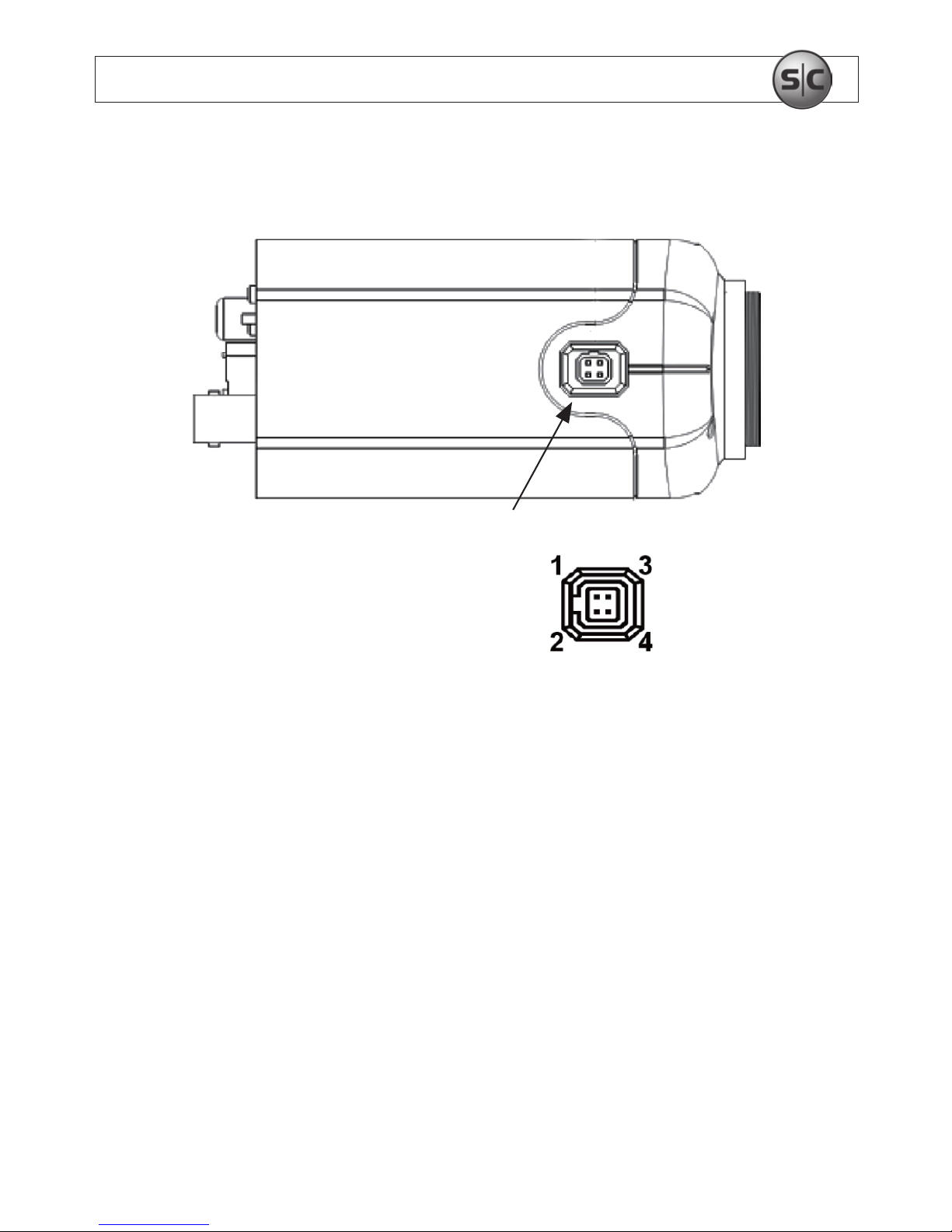
Side View
Auto-Iris Jack
Auto-IrisJack
PinAssignments
Pin DCDriver
1 - Control
2 + Control
3 - Drive
4 + Drive
Page 8
4
www.supercircuits.com
SECTION 1: FEATURES
1.2 System options
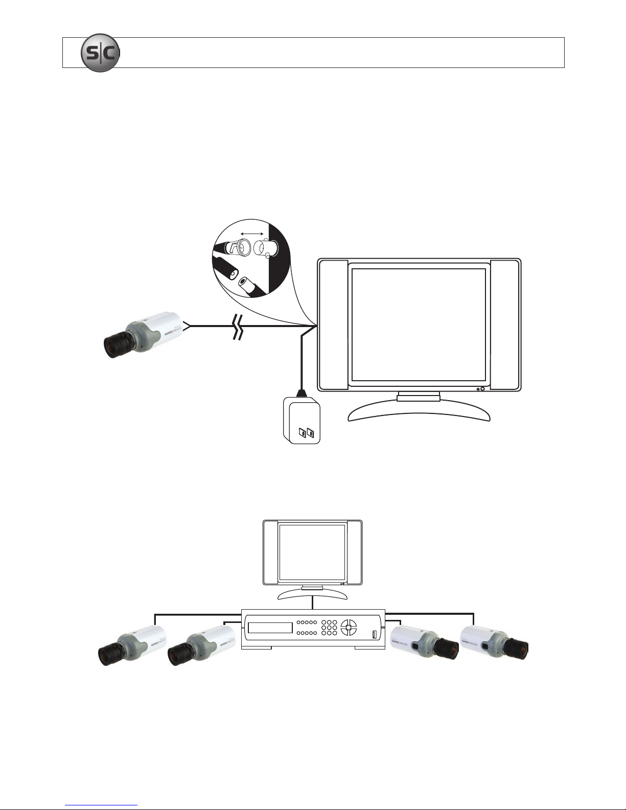
The camera can be connected to a CCTV monitor or to a DVR.
Connect
Multiple camera system with DVR and monitor
Multiple camera system with DVR and monitor
Page 9

5
Color Box Camera User Manual
SECTION 2: INSTALLATION
SECTION2 Installation
2.1 What’s in the box
The camera package contains:
• Camera assembly
• Instruction manual
• Hex wrench
2.2 What you need
To install the camera, you will need:
• C/CS type lens (PC33C5G and PC153C5G)
• Mounting bracket, such as a Supercircuits SKU MB14
• Hardware and tools to attach the mounting bracket to the mounting surface
• Video, audio, and power extension cables
• 12 VDC or 24 VAC power adapter
2.3 Installing the camera
This procedure steps through the installation of a C/CS mount box camera using the
Supercircuits MB14 mounting bracket (sold separately). If you are using a dierent
Page 10
6
www.supercircuits.com
SECTION 2: INSTALLATION
mounting bracket, this procedure can serve as a general guideline for installing your
equipment.
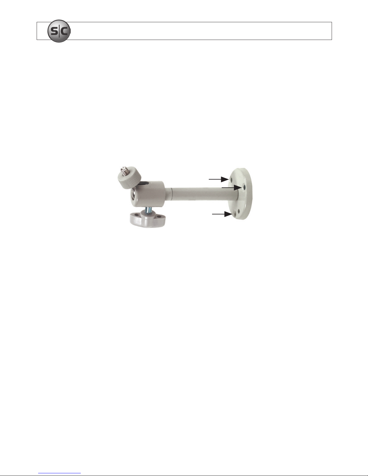
1. Using the bracket mounting plate as a template, mark the location of the mounting
screw holes on the mounting surface.
Camera attachment
screw
Mounting screw
locations
Directional
adjustment screw
Use the mounting bracket to mark holes for mounting screws
2. Drill mounting screw holes into the mounting surface.
3. Attach the bracket to the mounting surface.
4. Attach a lens assembly to the camera, if needed. Use the instructions provided with
the lens.
5. If you installed an auto-iris lens on the camera, plug the lens cable into the AUTO
IRIS connector on the side of the camera.
Page 11
7
Color Box Camera User Manual
SECTION 2: INSTALLATION
6. Loosen the directional adjustment screw so that the camera adjustment screw moves
freely.
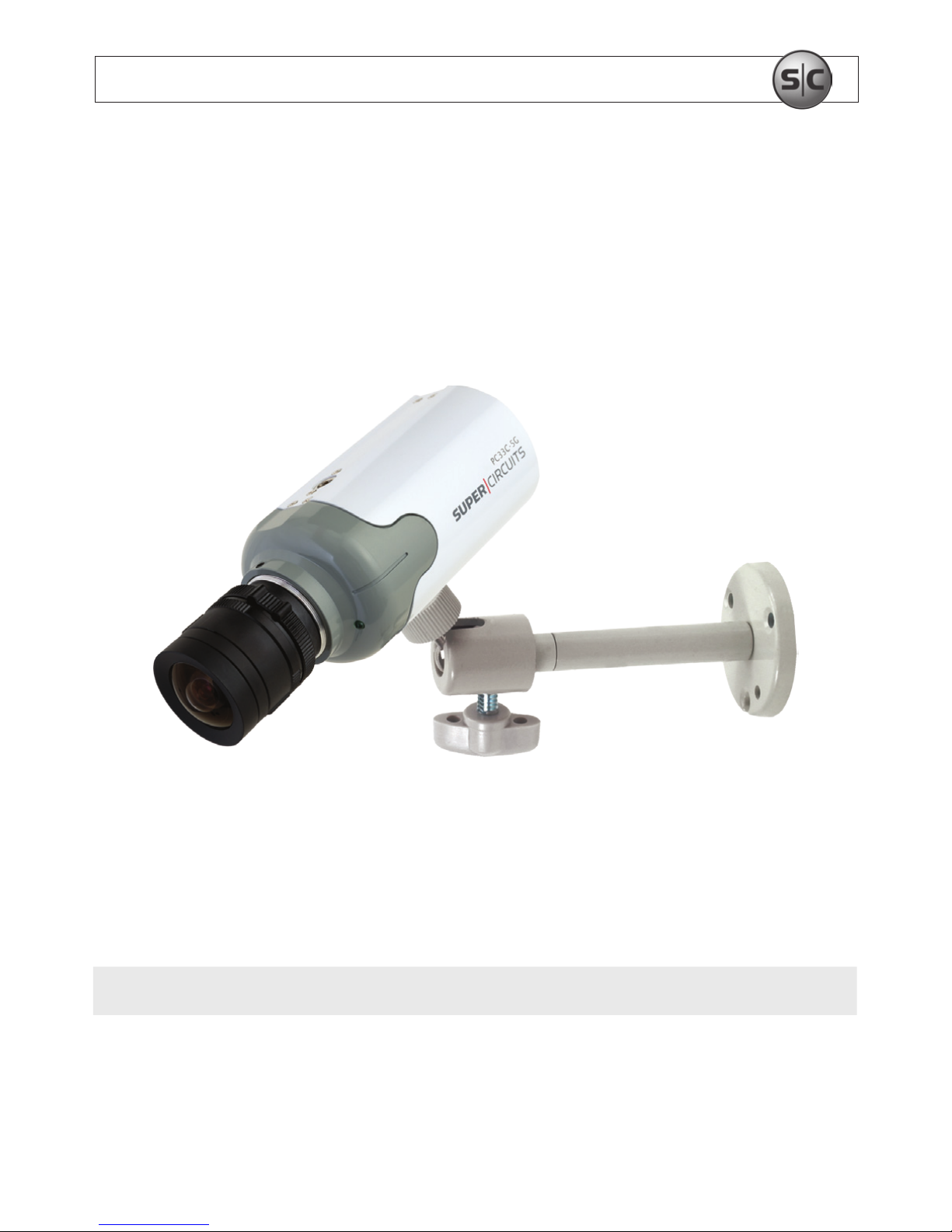
7. Attach the camera to the mounting bracket by tightening the camera attachment
screw into the mounting bracket connector.
8. Tighten the directional adjustment screw to hold the camera in position.
9. Attach video, audio, and power extension cables to the connectors on the back of the
camera.
NOTE
Connectors on power cables are usually dierent at each end.
10. Attach the video and audio extension cables to a monitor or DVR.
Page 12

8
www.supercircuits.com
SECTION 2: INSTALLATION
11. Attach the power extension cable to a 12 VDC adapter or power source and power on
the camera.
12. Verify that video from the camera can be seen on the monitor.
2.4 Aiming the Camera
1. While observing video from the camera, hold the camera in place and loosen the
directional adjustment screw until the camera can move freely.
2. Point the camera at the center of your surveillance target. Correct the horizontal
alignment of the picture, and then tighten directional adjustment screw.
3. Set the zoom and focus to produce the best framing and clarity of your surveillance
target.
a. If your camera has a manual iris adjustment, rotate the aperture ring to produce
the best picture quality.
b. If your camera lens has an direct drive auto-iris lens, adjust the LEVEL control
to produce the best picture quality during average brightness levels of your
surveillance target.
Page 13
9
Color Box Camera User Manual
SECTION 3: SETUP MENU USAGE
SECTION3 SETUP Menu (OSD) Usage
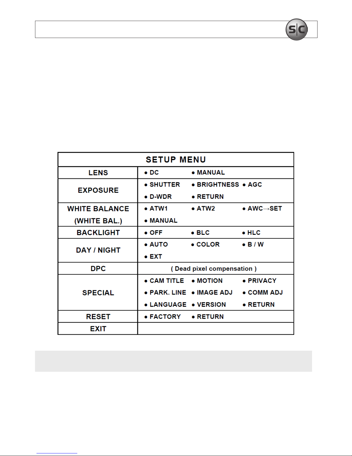
The SETUP menu can be accessed and congured using the function setup joystick on the
back of the camera, or through an RS-485 interface. It appears as an OSD over the video
image from the camera.
NOTE
Depending on the model of your camera, some SETUP menu options may not be
available.
Page 14
10
www.supercircuits.com
SECTION 3: SETUP MENU USAGE
To access the SETUP menu:
1. Connect a video monitor to the video connector on the back of the camera.
2. While observing video from the camera, press the joystick in (toward the camera
backplate) to open the SETUP menu.
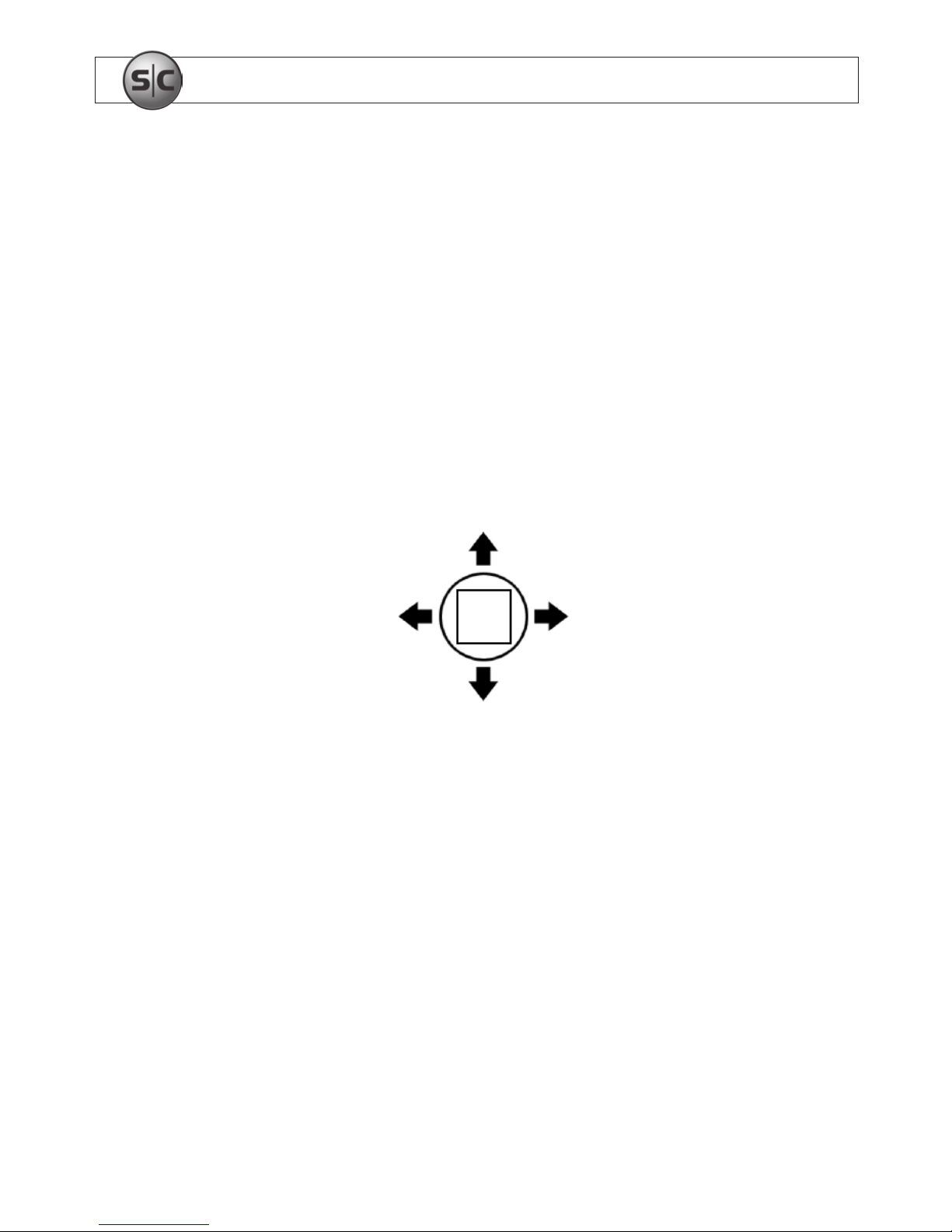
3. Navigate through the menu system and select options as needed:
— Rock the joystick up, down left, or right to navigate through the menu tree.
SET
Up
Left
Down
Right
— Press the joystick in (toward the camera backplate) to open a submenu or select
(SET) an option.
3.1 SETUP menu options
LENS
• DC: Select when using an Auto-iris lens.
Page 15

11
Color Box Camera User Manual
SECTION 3: SETUP MENU USAGE
• Manual: Select for manual lenses.
EXPOSURE
• SHUTTER: Select either auto or manual shutter.
— AUTO: Select for auto shutter. Default: 1/60 sec
— FLK: Select for Flicker shutter. Select from 1/250 ~ 1/100000 sec shutter time.
• BRIGHTNESS: Adjust as needed. Range: 0 ~ 255 steps.
• AGC (Automatic Gain Control): The higher the gain, the brighter the screen and the
higher the noise level.
— OFF: Deactivate AGC.
— LOW: Allow AGC: 0 ~ 24dB.
— MIDDLE: Allow AGC: 0 ~ 33dB.
— HIGH: Allow AGC: 0 ~ 40dB
• D-WDR (Digital Wide Dynamic Range): Used to optimize the contrast between the
brightest and darkest points in the image.
— OFF: Deactivate the D-WDR.
— ON: Activate the D-WDR. Range: 0 ~ 63 steps
WHITE BAL. (white balance)
• ATW 1 / ATW 2: Select this option when the color temperature is between 1800°K
and 10500°K.
Page 16
12
www.supercircuits.com
SECTION 3: SETUP MENU USAGE
• AWC g SET: To nd the optimal setting for the current luminance environment in
this mode, point the camera towards a sheet of white paper then press SET.
NOTE
When the environment changes, repeat this procedure.
• MANUAL: Select this mode to manually set the white balance. First, set the White
Balance using the INDOOR or OUTDOOR mode, then switch to MANUAL mode, netune the White Balance, and press SET.
— COLOR TEMP:
INDOOR: Select this when the color temperature is between 4500°K and 8500°K.
OUTDOOR: Select this when the color temperature is between 1800°K and
10500°K. (sodium light inclusion)
MANUAL: Set the appropriate color temperature that increases / decreases the
red and blue color values. Monitor the color changes of the object.
BLUE: Remove or add more blue color by rocking the joystick left or
right. Range: 0 ~ 255 steps
RED: Remove or add more red color by rocking the joystick left or
right. Range: 0 ~ 255 steps
NOTE
White Balance may not work properly under the following conditions. In this case, select
AWC mode.
1. When the color temperature of environment surrounding the subject is out of control
range (e.g. clear sky, or sunset)
2. When the ambient illumination of the subject is dim.
3. If the camera is pointed at a uorescent light or is installed in a place where
illumination changes dramatically, the White Balance operation may be unstable.
Page 17

13
Color Box Camera User Manual
SECTION 3: SETUP MENU USAGE
BACKLIGHT
• OFF: Deactivate the BACKLIGHT Function.
• BLC: Enable to select an area of a picture to view more clearly.
— AREA SEL: AREA 1 / AREA 2
— AREA STATE: ON /OFF
— GAIN: Adjust the value between. Range: 0 ~ 255 steps
— HEIGHT: Adjust the area height
— WIDTH: Adjust the area width
— LEFT / RIGHT: Move select area to the left or right
— TOP / BOTTOM: Move select area up or down
• HLC: If there is a bright light installed in a limited environment, such as an apartment
parking garage or gas station entrance, removing the light improves the view of car
license plates.
— LEVEL: Adjust the value. Range: 0 ~ 255 steps
• MODE: NIGHT ONLY / ALL DAY. Select HLC to activate during NIGHT ONLY or ALL DAY.
NOTE
Because the eectiveness of HLC depends on the amount of light area on the screen,
optimize the installation angle for best HLC performance. In a dark environment, HLC is
activated only when a high light is present. The HLC is not activated in bright or overly
dark condition.
Page 18
14
www.supercircuits.com
SECTION 3: SETUP MENU USAGE
DAY / NIGHT
• AUTO: This mode is set for color in a normal environment, but switches to B / W
mode when ambient illumination is low. To set up the switching time or speed for
AUTO mode.
— D g N LEVEL: Adjust the Start Night level. Range: 0 to 255 steps
— D g N DELAY: Adjust the Start Night Delay time. Options: 1 / 3 / 5 / 10 / 15 /
20 / 25 / 30 seconds.
— N g D LEVEL: Adjust the End Night level. Range: 0 to 255 steps
— N gD DELAY: Adjust the End Night Delay time. Options: 1 / 3 / 5 / 10 / 15 /
20 / 25 / 30 seconds.
• COLOR: The picture is always displayed in color.
• B / W: ON / OFF. When ON, the picture is always displayed in black and white.
— BURST: ON / OFF. Burst signal is o during B/W mode.
— IR SMART: ON / OFF. IR GAIN: 0 ~ 255 steps; HEIGHT: 0 ~ 8 steps;
WIDTH: 0 ~ 13 steps; LEFT/RIGHT: 0 ~ 7 steps; TOP/BOTTOM: 0 ~ 10 steps
— IR LEVEL: LOW / HIGH
• EXT: This mode is used to apply a lter to external signals.
NOTE
- When using a video auto-iris lens, automatic switching between Color and B/W may
not occur if the level is set too low.
- The AGC in the EXPOSURE menu is “OFF” when DAY / NIGHT menu is “AUTO”.
- If using IR illumination, install an Extra-low Dispersion Lens to improve camera focus.
- For IR models, the Day and Night menu contains only the “Auto” option.
Page 19
15
Color Box Camera User Manual
SECTION 3: SETUP MENU USAGE
• DPC (Dead pixel compensation). To set the DPC, cover the lens, then select DPC and
press SET.
• SPECIAL
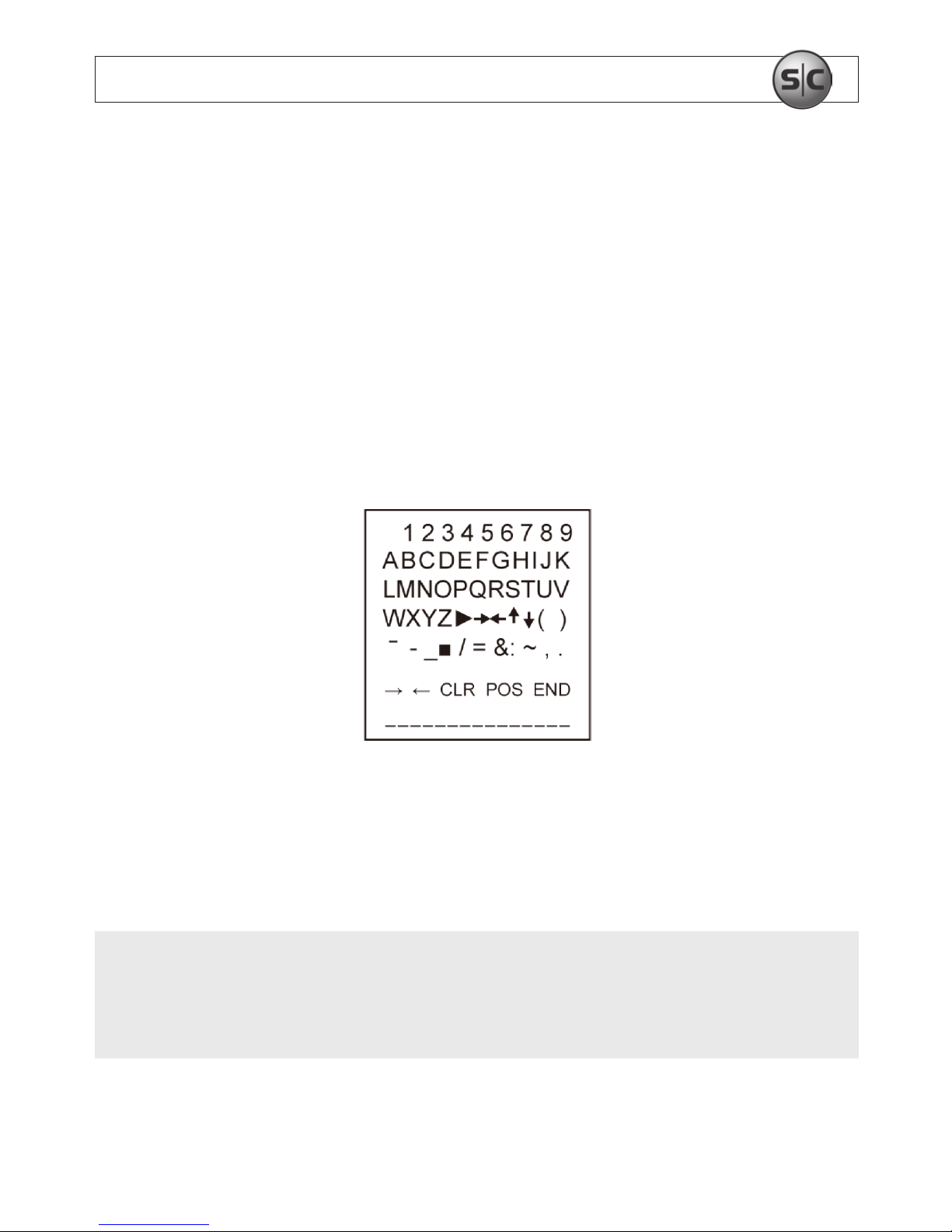
— CAM TITLE: If you enter a title, the title will appear on the image.
OFF: No title will be displayed on the monitor.
ON: Press SET to enter the submenu. Rock the joystick up, down left or right to
move to a desired letter, then press SET to select it. Repeat this method to enter
multiple letters. The CAM TITLE can be up to 15 letters in length.
To position the title on the screen, move the cursor to “POS”, then press SET. Use the
joystick to move the title to the preferred position, then press SET. Select “END” and
press the SET to return to the SPECIAL menu.
NOTE
If you move the cursor to CLR and press SET, all the letters are deleted. To edit a single
letter, move the cursor to the joystick left arrow, then press SET. Move the cursor to the
letter being removed, then press SET. Move the cursor over the letter to be inserted, then
press SET again.
Page 20

16
www.supercircuits.com
SECTION 3: SETUP MENU USAGE
• MOTION: If you connect an alarm device to the camera, you can monitor activities
more eciently because a signal is generated by the camera whenever a motion is
detected. The motion detection signal is output through the MD OUT port.
— OFF: Deactivate the MOTION function.
— ON: Activate the MOTION function.
AREA SELECT: You can select up to 4 areas to monitor for motion.
AREA STATE: Determine whether to use the area selected.
HEIGHT: Adjust the height of the area.
WIDTH: Adjust the width of the area.
LEFT / RIGHT: Adjust position of the area left or right.
TOP/BOTTOM: Adjust position of the area up or down.
DEGREE: Range: 0 ~ 255 steps
VIEW: ON / OFF
• PRIVACY: ON / OFF. The Privacy feature allows you to hide an area of the screen.
— AREA SELECT: You can select up to 8 areas.
— AREA STATE: Determines whether to use the area selected.
— HEIGHT: Adjust the height of the area.
— WIDTH: Adjust the width of the area.
— LEFT / RIGHT: Adjust position of the area.
— TOP / BOTTOM: Adjust position of the area.
— COLOR: Determine area color. You can select 15 kinds of color.
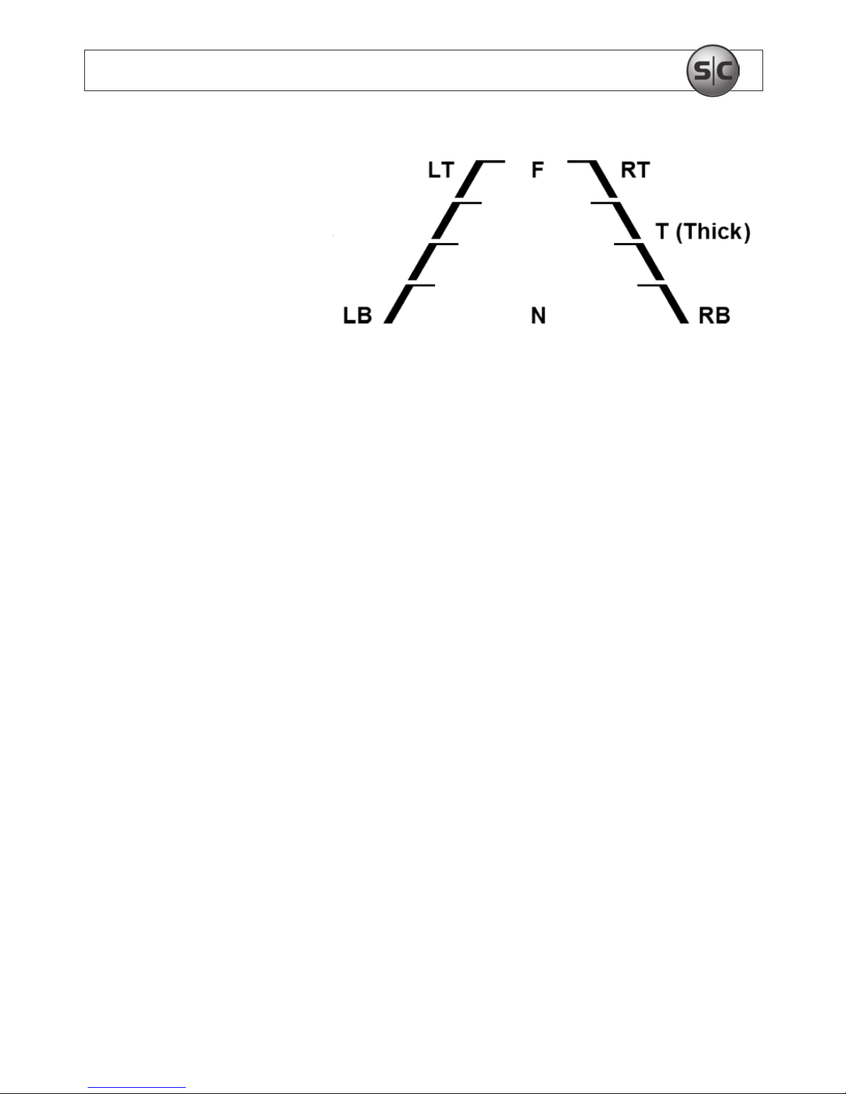
• PARK. LINE: The Park Line feature can be useful when the camera is installed in
vehicles as a backup camera. Adjust as necessary. Parameters set the position of the
parking lines. See the diagram to the right.
Page 21
17
Color Box Camera User Manual
SECTION 3: SETUP MENU USAGE
— LT: 0 ~ 194
— RT: 0 ~ 194
— LB: 0 ~ 194
— RB: 0 ~ 194
— F: 0 ~ 80
— N: 0 ~ 80
— T: 2 ~ 15
• IMAGE ADJ:
— LENS SHAD: ON / OFF. Range: O ~ 255 steps
— 2DNR: This function reduces background noise in a low luminance environment.
ON: Activate DNR.
OFF: Deactivate DNR. Noise is not reduced.
— MIRROR: ON / OFF. You can ip or rotate the image.
— FONT COLOR:
FONT: 0 ~ 15
ID / TITLE: 0 ~ 15
— CONTRAST. Range: 0 ~ 255 steps
— SHARPNESS. Range: 0 ~ 31 steps
— DISPLAY
LCD ADJUST: GAMMA, PED LEVEL, COLOR GAIN
USER ADJUST: GAMMA, PED LEVEL, COLOR GAIN
— CRT ADJUST: PED LEVEL, COLOR GAIN
• NEG. IMAGE: ON / OFF. Set a negative image eect.
Page 22

18
www.supercircuits.com
SECTION 3: SETUP MENU USAGE
NOTE
In the LENS SHAD menu, IR models provide only the OFF option.
• COMM ADJ (communication adjustment): Use function to set up the communication
status between the camera and an external controller. NOTE: PC33C5G and
PC153C5G cameras do not support PTZ.
— CAM ID: Set the camera ID number. Range: 0 ~ 255
— BAUD RATE: Select either 2400 / 4800 / 9600 / 19200 / 38400 / 57600 bps.
— PROTOCOL: Select either PELCO - D, PELCO - F, or NEX TCHIP.
— DISPLAY ID: Display camera title on the screen.
— ID POS: Use the joystick to set the position where the ID is displayed.
• LANGUAGE: Use to select the preferred menu language.
• VERSION: 21 01 10
RESET
• FACTORY: Reset the camera setting to the factory defaults.
• RETURN: Select this return to the SETUP menu.
EXIT
Press SET in the EXIT menu to save the current setting and exit the SETUP menu.
Page 23
19
Color Box Camera User Manual
SECTION 4: CLEANING
SECTION4 Cleaning
Clean the camera lens and IR lamp shield with an approved glass cleaning solution and a
lint free cloth.
• Remove all foreign particles, such as plastic or rubber materials, attached to the
camera housing. These may cause damage to the surface over time.
• Dust can be removed from the unit by wiping it with a soft damp cloth. To remove
stains, gently rub the surface with a soft cloth moistened with a mild detergent
solution, then rinse and dry it with a soft cloth.
CAUTION
Do not use benzene, thinner or other chemical products on the camera assembly;
these may dissolve the paint and promote damage of the surfaces. Before using
any chemical product, read the accompanying instructions carefully.
Page 24
20
www.supercircuits.com
SECTION 5: SPECIFICATIONS
SECTION5 Specications
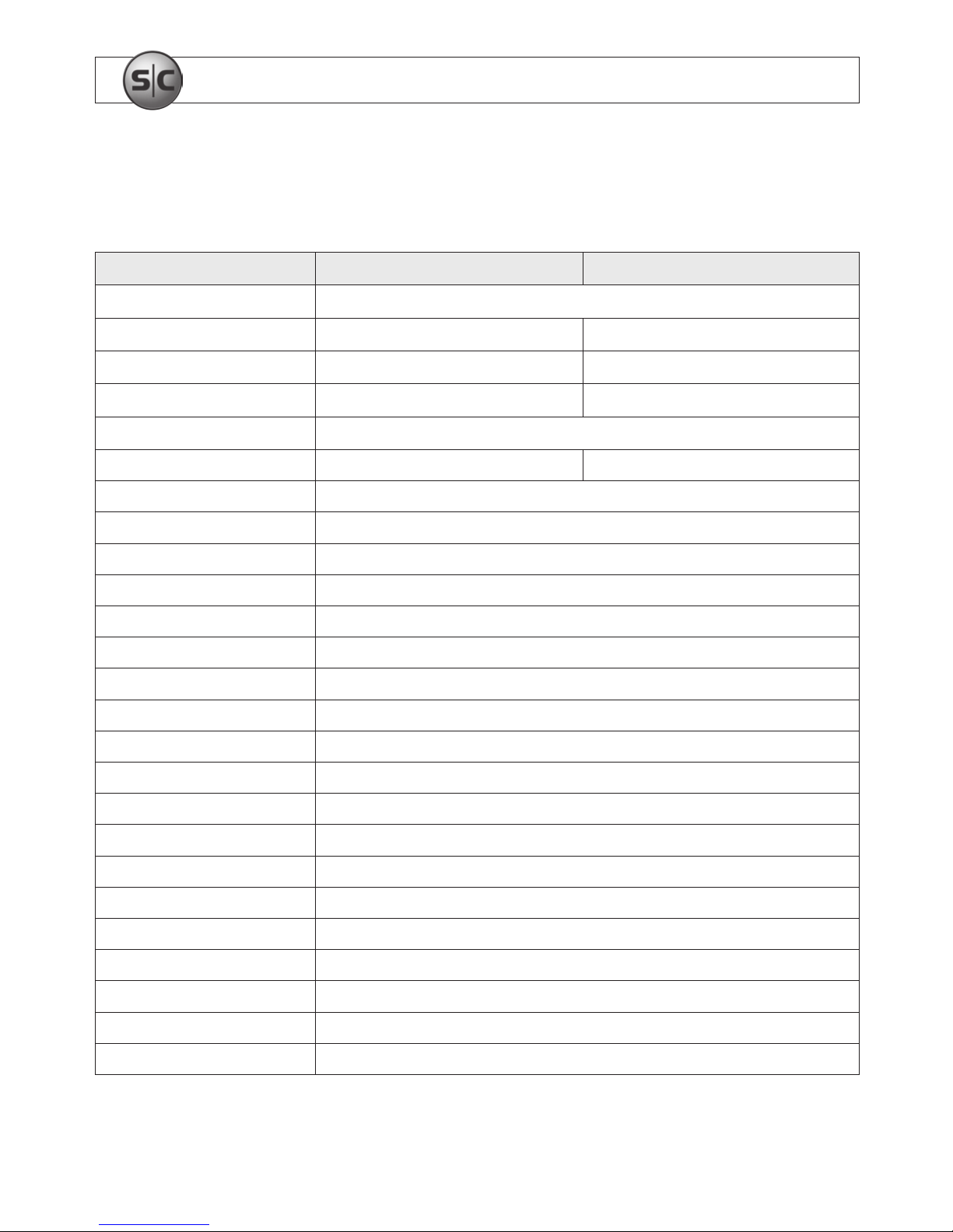
Model PC33C5G PC153C5G
Image Sensor 1/3” Sony CCD
Total Pixels 811(H) x 504(V) 537(H) x 505(V)
Eective Pixels 768(H) x 494(V) 510(H) x 492(V)
Resolution Color: 600 TV Line B/W: 700 TV Line Color: 450 TV Line B/W: 500 TV Line
S/N (Y Signal) 52dB (AGC OFF, Weight ON)
Min Illumination 0.1 LUX 0.05 LUX
Scanning System 2:1 Interlace
Synchronization Internal
DWDR OSD Control
Black Light BLC / HLC / OFF (selectable)
Electronic Shutter Speed 1/60 sec ~ 1/100,000 sec
White Balance OSD Control
Gain Control OSD Control
DNR OSD Control
D & N Selection OSD Control
Motion Detection OSD Control
Privacy OSD Control
Mirror (H-REV) OSD Control
Auto IRIS Lens Control OSD Control
Blemish Compensation OSD Control (DPC)
Video Output 1.0 Vp-p, 75 ohm LOAD
Audio High sensitivity microphone
Lens Mount C / CS
Power Supply 12 VDC / 24 VAC
Power Consumption 350mA (max) @ DC12V
Page 25
21
Color Box Camera User Manual
SECTION 5: SPECIFICATIONS
Model PC33C5G PC153C5G
Operating Temperature 14°F ~ 113°F (-10°C ~ 45°C)
Storage Temperature 44°F ~ 140°F (-20°C ~ 60°C)
Dimensions (L x W x H) 4.43” x 2.04” x 2.38” (112.5mm x 60.33mm x 51.93mm)
Weight 7.05 oz ± 0.35 oz (200 g ± 10 g), camera body
Page 26

22
www.supercircuits.com
APPENDIX A: TROUBLESHOOTING
APPENDIXA Troubleshooting
Before sending the camera for repair, please follow the suggestions listed below and make
sure that the camera is installed correctly. If it still does not perform adequately, please
consult your supplier or contact Technical Support at 1.800.335.9777.
1. No picture on the monitor screen.
a. Check that all connected devices are powered on.
b. Conrm that the voltage is correct.
c. Conrm that the power supply provides enough current to power the camera.
d. Check that all video cables are correctly connected.
2. The picture is not clear.
a. Check that your monitor is correctly adjusted.
b. Conrm that the glass in front of the lens is clean. If there is dust, dirt or
ngerprints on the glass, the image quality will be aected. To clean the glass
use a soft, dry and non-abrasive cloth or a commercially available lens cleaning
set.
3. The picture has interference.
a. The camera may be close to a high voltage source, such as a power generator.
b. The BNC cable may not be terminated properly.
Page 27
23
Color Box Camera User Manual
APPENDIX A: TROUBLESHOOTING
c. The video cables are not connected properly.
CAUTION
This camera is a precision instrument and when treated with care, will
provide years of satisfactory performance. If a problem does occur, do not
open the camera to make repairs. Servicing should always be referred to
your supplier.
Page 28
24
www.supercircuits.com
APPENDIX B: DIMENSIONS
APPENDIXB Dimensions
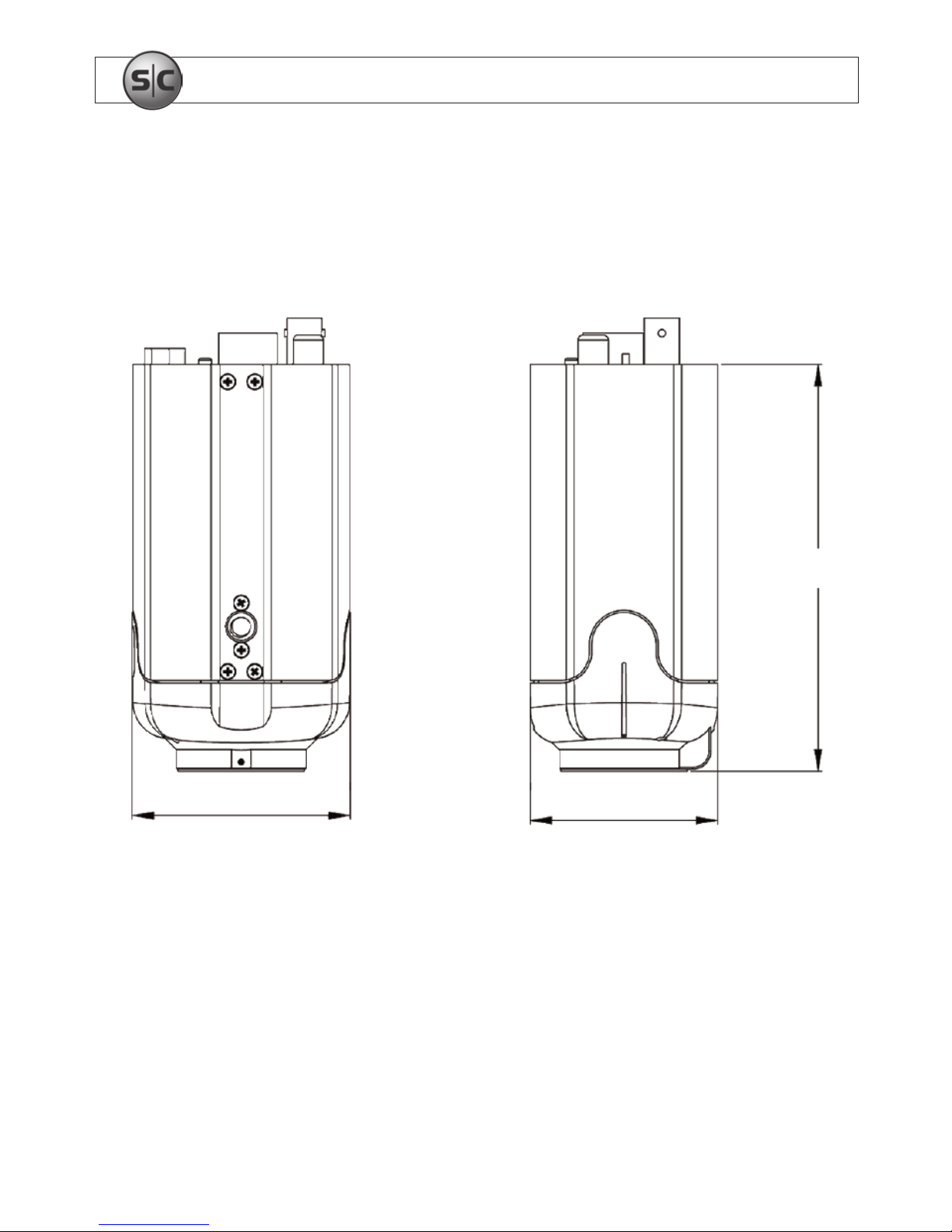
For cameras: PC33C5G_CM and PC153C5G
4.43”
2.04”
2.38”
 Loading...