

Page 1
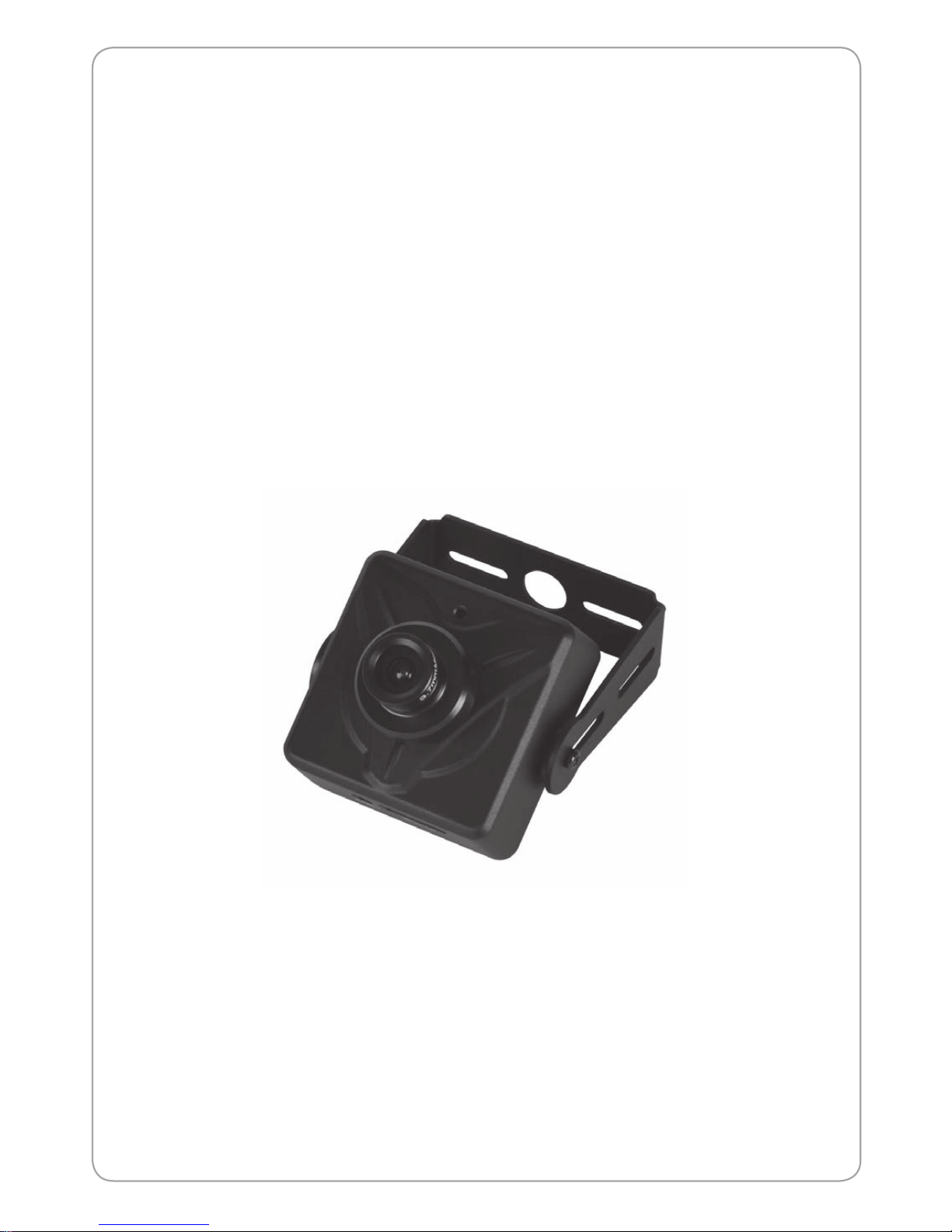
PC2MP-UXP
Megapixel Network Camera
USER MANUAL
Before installing and using the camera, please read this manual carefully,
Be sure to keep it handy for later reference
Page 2

Network Dome Camera User’s Manual
Network Dome Camera User’s Manual
2
About This Document
This manual is intended for administrators and users of the PC2MP-UX.
It includes instructions for using and managing the Network
Camera on your network. Previous experience of networking will be of use when installing and
using this product. Some knowledge of UNIX or Linux-based systems would also be beneficial, for
developing shell scripts and applications. Later versions of this document will be posted to the provider
Website, as required. See also the product’s online help, available via the Web-based interface.
Safety Notices Used In This Manual
Caution! – Indicates a potential hazard that can damage the product.
Important! – Indicates a potential hazard that can seriously impair operation.
Do not proceed beyond any of the above notice until you have fully understood the implications.
Legal Considerations
Camera and audio surveillance can be prohibited by laws that vary from country to country. Check the
laws in your local region before using the product for surveillance purposes.
Electromagnetic Compatibility
This equipment generates, uses, and can radiate radio frequency energy and, if not installed and
used in accordance with the instructions, may cause harmful interference to radio communications.
However, there is no guarantee that interference will not occur in a particular installation. If this
equipment does cause harmful interference to radio or television reception, which can be determined
by turning the equipment off and on, the user is encouraged to try to correct the interference by
one or more of the following measures: Re-orient or relocate the receiving antenna. Increase the
separation between the equipment and receiver. Connect the equipment to an outlet on a different
circuit to the receiver. Consult your dealer or an experienced radio/TV technician for help. Shielded
(STP) network cables must be used with this unit to ensure compliance with EMC standards.
USA –
This equipment has been tested and found to comply with the limits for a Class A digital
device, pursuant to Part 15 of the FCC Rules.
These limits are designed to provide reasonable protection against harmful interference when the
equipment. This equipment generates, uses, and can radiate radio frequency energy and, if not
installed and used in accordance with the instruction manual, may cause harmful interference to radio
communications.
Operation of this equipment in a residential area is likely to cause harmful interference in which case
the user will be required to correct the interference at his own expense.
WARNING
This is a class A product. In a domestic environment this product may cause radio interference in
which case the user may be required to take adequate measures.
Europe –
This digital equipment fulfills the requirements for radiated emission according to Class
A of EN55022/2006, and the requirements for immunity according to EN55024/1998 residential,
commercial, and light industry.
Liability
Every care has been taken in the preparation of this manual; please inform your provider's office
of any inaccuracies or omissions. Your provider cannot be held responsible for any technical or
typographical errors and reserves the right to make changes to the product and manuals without prior
notice. Your provider makes no warranty of any kind with regard to the material contained within
this document, including, but not limited to, the implied warranties of merchantability and fitness for
a particular purpose. Your provider shall not be liable or responsible for incidental or consequential
damages in connection with the furnishing, performance or use of this material.
Trademark Acknowledgments
Ethernet, Internet Explorer, Linux, Microsoft, Mozilla, OS/2, UNIX, Windows, WWW are registered
trademarks of the respective holders. QuickTimeTM is a trademark of Apple Inc., registered in the
U.S. and other countries. Java and all Java-based trademarks and logos are trademarks or registered
trademarks of Oracle Corporation, Inc. in the United States and other countries. MV Co., Ltd. is
independent of Oracle Corporation Inc. UPnPTM is a certification mark of the UPnPTM Implementers
Corporation.
Support Services
Should you require any technical assistance, please contact your product reseller. If your questions
cannot be answered immediately, your reseller will forward your queries through the appropriate
channels to ensure a rapid response. If you are connected to the Internet, you can:
• Download user documentation and firmware updates.
• Find answers to resolved problems in the FAQ database. Search by product, category, or phrases.
• Report problems to the provider's support staff by logging in to your private support area.
Page 3
Network Dome Camera User’s Manual
Network Dome Camera User’s Manual
3
Cautions
This device complies with Part 15 of the FCC Rules.
Operation is subject to the following two conditions;
1. This device may not cause harmful interference.
2. This device must accept any interference received, including interference that may cause undesired operation.
Note
This equipment has been tested and found to comply with the limits for a Class A digital device, pursuant
to part 15 of the FCC Rules. These limits are designed to provide reasonable protection against harmful
interference when the equipment is operated in a commercial environment. This equipment generates, uses,
and can radiate radio frequency energy and, if not installed and used in accordance with the instruction
manual, may cause harmful interference to radio communications. Operation of this equipment in a
residential area is likely to cause harmful interference in which case the user will be required to correct the
interference at his own expense.”
WARNING
This is a class A product. In a domestic environment this product may cause radio interference in which case
the user may be required to take adequate measures.
Caution
Any changes or modications in construction of this devices which are not expressly approved by the party
responsible for compliance could void the user’s authority to operate the equipment.
CAUTION
1.
2.
3.
4.
5.
6.
7.
A regulated DC12V 1A power supply is recommended for use with this camera for the best picture and the
most stable operation. An unregulated power supply can cause damage to the camera. When unregulated
power supply is applied, product warranty will be out of subject.
It is recommended that the camera is used with a monitor that has a CCTV quality 75 video impedance
level. If your monitor is switched to high impedance then please adjust accordingly.
Do not attempt to disassemble the camera to gain access to the internal components. Refer servicing to
your dealer.
Never face the camera towards the sun or any bright or reective light, which may cause smear on the
picture and possible damage to the CCD.
Do not remove the serial sticker for the warranty service.
Do not expose the camera to rain or other types of liquid.
The apparatus must be connected to a mains socket-outlet with a protective earthing connection.
Correct Disposal of This Product
(Waste Electrical & Electronic Equipment)
(Applicable in the European Union and other European countries with separate collection systems)
This marking shown on the product or its literature, indicate that it should not be disposed with other
household wastes at the end of its working life. To prevent possible harm to the environment or human health
from uncontrolled waste disposal, please separate this from other types of wastes and recycle it responsibly to
promote the sustainable reuse of material resources. This product should not be mixed with other commercial
wastes purchased this product, or their local government ofce, for details of where and how they can take
item for environmentally safe recycling. Business users should contact their supplier and check the terms
and conditions of the purchase contract. Household users should contact either the retailer where they for
disposal.
CAUTION
RISK OF ELECTRIC SHOCK DO NOT OPEN
CAUTION: TO REDUCE THE RISK OF ELECTRIC SHOCK, DO NOT REMOVE COVER (OR BACK). NO USER.
SERVICEABLE PARTS INSIDE. REFER SERVICING TO QUALIFIED SERVICE PERSONNEL
This symbol is intended to alert the user to the presence of un-insulated “dangerous voltage”
within the product’s enclosure that may be of sufcient magnitude to constitute a risk of electric
shock to persons.
This symbol is intended to alert the user to the presence of important operating and maintenance
(servicing) instructions in the literature accompanying the appliance
Page 4

Network Dome Camera User’s Manual
Network Dome Camera User’s Manual
4
IMPORTANT SAFETY INSTRUCTION
1) Read these instructions.
2) Keep these instructions.
3) Heed all warnings.
4) Follow all instructions.
5) Do not use this apparatus near water.
6) Clean only with dry cloth.
7) Do not block any ventilation openings. Install in accordance with the manufacturer’s instructions.
8) Do not install near any heat sources such as radiators, heat registers, stoves, or other apparatus
(including ampliers) that produce heat.
9) Do not defeat the safety purpose of the polarized or grounding-type plug. A polarized plug has two
blades with one wider than the other. A grounding type plug has two blades and a third grounding
prong. The wide blade or the third prong are provided for your safety. If the provided plug does not
t into your outlet, consult an electrician for replacement of the obsolete outlet.
10) Protect the power cord from being walked on or pinched particularly at plugs, convenience
receptacles, and the point where they exit from the apparatus.
11) Only use attachments/accessories specied by the manufacturer.
12) Use only with the cart, stand, tripod, bracket, or table specied by the manufacturer, or sold with
the apparatus. When a cart is used, use caution when moving the cart/apparatus combination to
avoid injury from tip-over.
13) Unplug this apparatus during lightning storms or when unused for long periods of time.
14) Refer all servicing to qualied service personnel. Servicing is required when the apparatus has
been damaged in any way, such as power-supply cord or plug is damaged, liquid has been spilled
or objects have fallen into the apparatus, the apparatus has been exposed to rain or moisture, does
not operate normally, or has been dropped.
Page 5

Network Dome Camera User’s Manual
Network Dome Camera User’s Manual
5
Table of Contents
CAUTIONS 3
IMPORTANT SAFETY INSTRUCTION 4
OVERVIEW 6
USING THE NETWORK CAMERA 9
CONFIGURING THE NETWORK CAMERA 13
BASIC > NETWORK 14
BASIC > USERS 15
BASIC > VIDEO > COMMON 16
BASIC > VIDEO > H.264 17
BASIC > VIDEO > MJPEG 18
BASIC > DATE & TIME 19
ADVANCED > CAMERA SETTING 20
ADVANCED > EVENT SERVER 21
ADVANCED > EVENT ACTIONS 22
Action conguration for [Motion Detection + Upload Image + FTP] 24
Action conguration for [Motion Detection + Upload Image + E-mail] 25
Action conguration for [Motion Detection + Activate output] 26
Action conguration for [Motion Detection + E-mail Notication] 27
Action conguration for [Sensor Input + Upload Image + FTP] 28
Action conguration for [Sensor Input + Upload Image + E-mail] 29
Action conguration for [Sensor Input + Activate Output] 30
Action conguration for [Sensor Input + E-mail Notication] 31
Action conguration for [Manual Trigger + Upload Image + FTP] 32
Action conguration for [Manual Trigger + Upload Image + E-mail] 33
Action conguration for [Manual Trigger + Activate Output] 34
Action conguration for [Manual Trigger + E-mail Notication] 35
Action conguration for [Network Fail + Activate Output] 36
Action conguration for [Reboot] 37
ADVANCED > MOTION SETTINGS 38
ADVANCED > SMTP 40
ADVANCED > ADVANCED NETWORK 41
ADVANCED > HTTPS 43
ADVANCED > MASK 45
ADVANCED > LIVE VIEW LAYOUT 47
ADVANCED > IP ADDRESS FILTER 48
MAINTENANCE > INITIALIZE & UPGRADE 49
MAINTENANCE > LOGS 50
SUPPORT > SYSTEM / HELP 51
PRODUCT SPECIFICATIONS 52
TROUBLESHOOTING 54
GLOSSARY 55
Page 6
Network Dome Camera User’s Manual
Network Dome Camera User’s Manual
Overview
Features
Thank you for purchasing a network surveillance product.
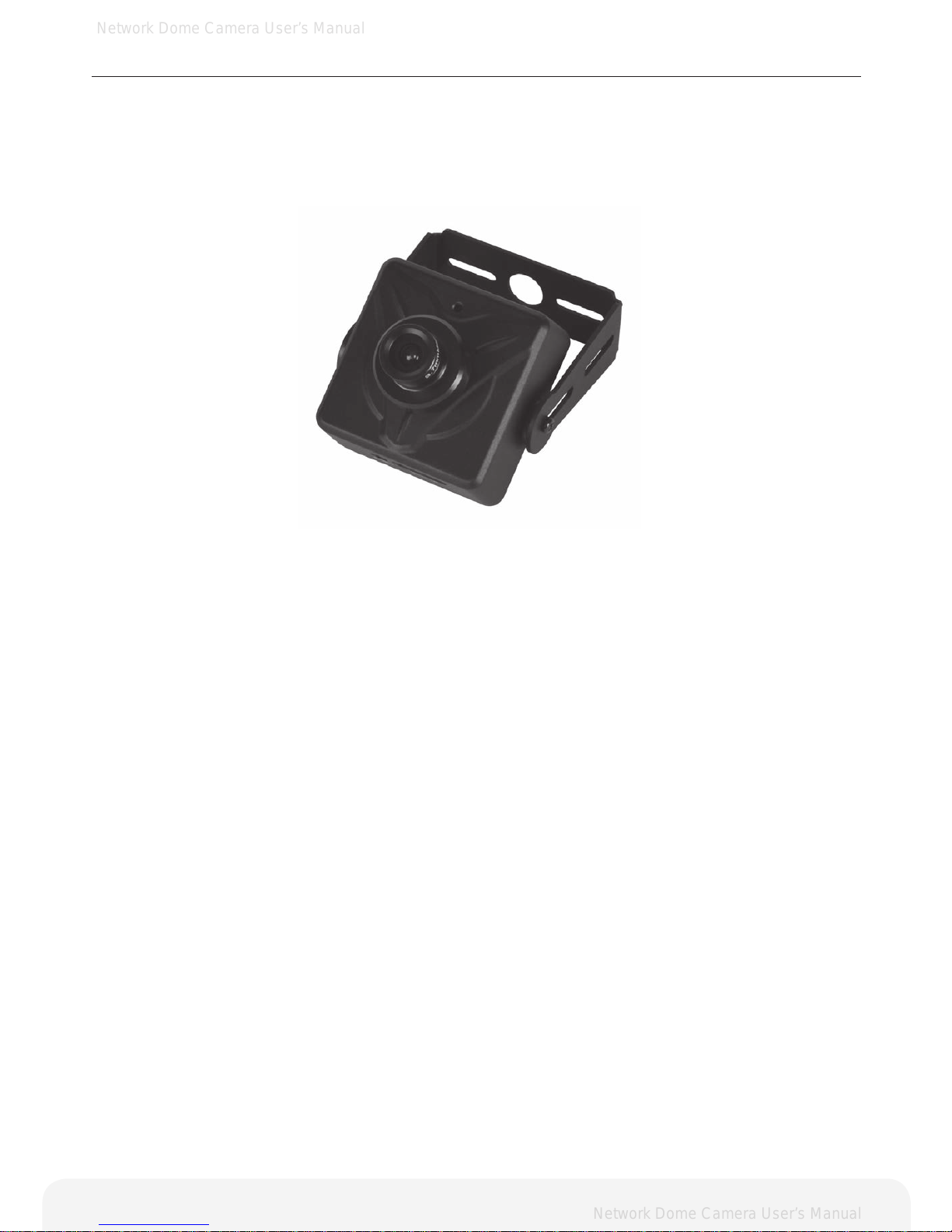
PC2MP-UXP is a high-performance, Megapixel Network Camera which offers the perfect solution for
integrating network-based video surveillance system.
Key Features
- Onvif 1.0
- Simultaneous H.264 and MJPEG video streams at up to 30 fps in 1920x1080 resolution
- Power over Ethernet (PoE Class 3)
- Multi-area motion detection
- Powerful event management
- Upgradeable rmware
System requirements for a PC
- Pentium® 4 CPU 2.4 GHz or higher, or equivalent AMD®
- 1 GB RAM
- AGP graphics card 64 MB RAM, Direct Draw
- CD-ROM drive (for using User’s Manual and software)
- Microsoft® Windows® XP, 2000, 2003 Server, Vista, Window 7
- DirectX® 9.0 or later
- Microsoft® Internet Explorer® 7.x or later(32bit)
- Adobe® Reader® (for reading User’s Manual in CD-ROM)
6
Page 7
Network Dome Camera User’s Manual
Network Dome Camera User’s Manual
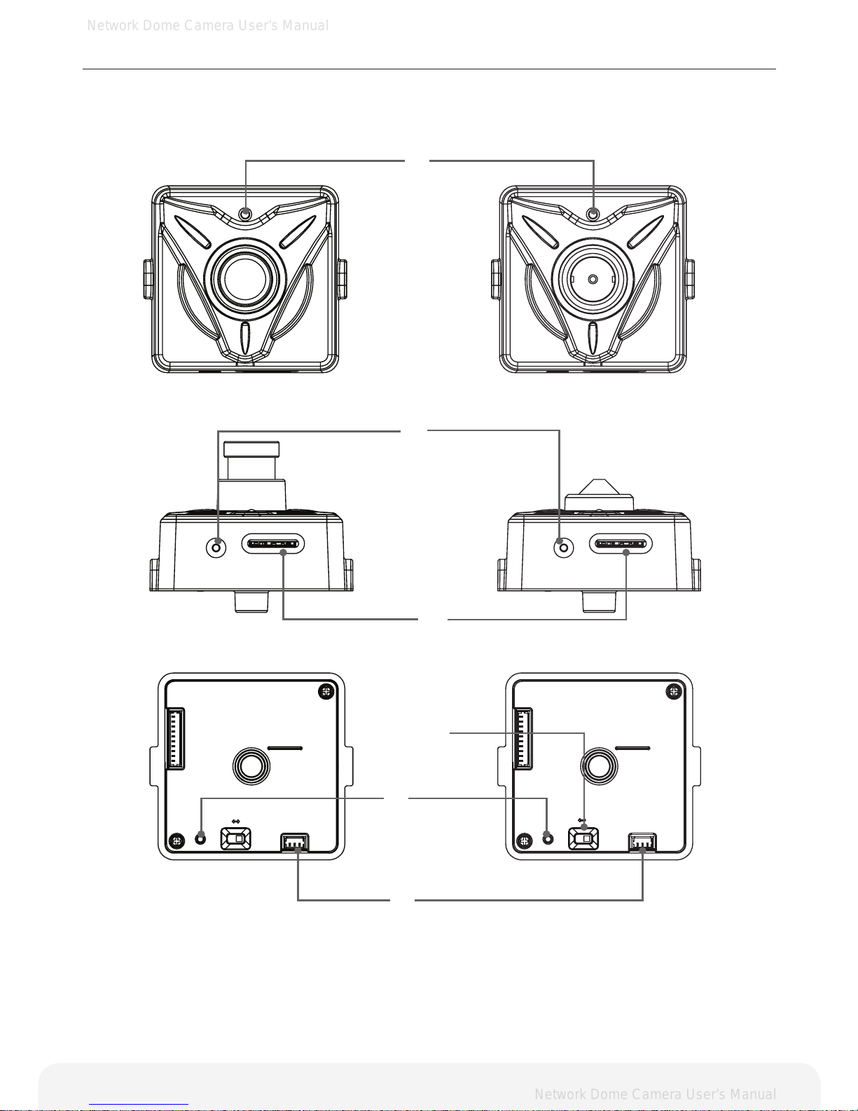
Product Description
Description and function
7
➊
➏
➋
➎
Reset
Micro SD
NTSC
SERVICE
VIDEO OUT
PAL
Reset
Micro SD
NTSC
SERVICE
VIDEO OUT
PAL
➌
➍
Page 8
Network Dome Camera User’s Manual
Network Dome Camera User’s Manual
8
Product Description
Description and function
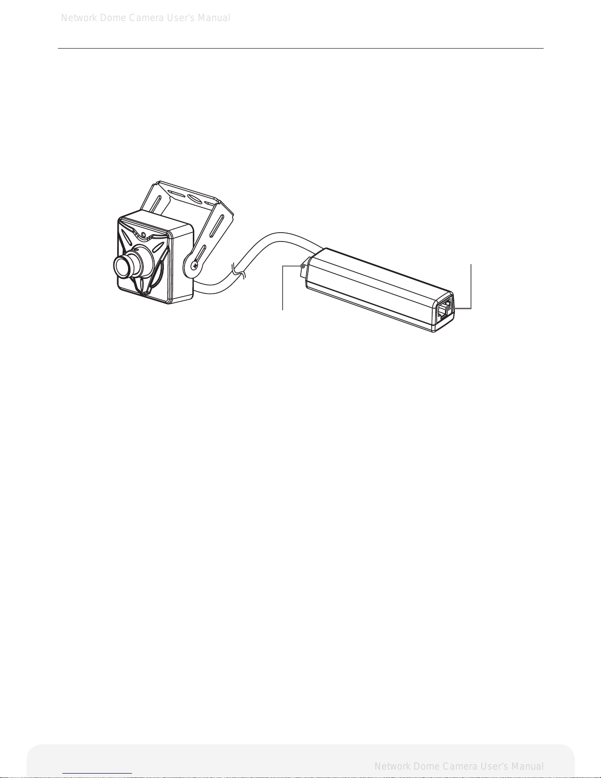
1. Reset Button – Resets the product to the factory default settings.
2. Service Video Connector – Outputs video to the monitor.
3. Status LED
4. Hole
5. Micro SD Card Socket.
6. NTSC / PAL slide Switch.
7. Power Input(DC12V) – Connect DC 12V power.
8. Network Connector –
The Network Camera connects to the network via a standard network cable, and automatically detects the
speed of the local network segment (10BaseT/100BaseTX Ethernet). PoE Supported
➐
➑
Page 9
Network Dome Camera User’s Manual
Network Dome Camera User’s Manual
9
Using the Network Camera
The Network Camera can be used with either Internet Explorer or Central Monitoring System (CMS) in
Microsoft Windows operating systems.
Note: For information on installing the Network Camera, please refer to the Installation Guide.
Accessing the Network Camera
1.
2.
3.
4.
5.
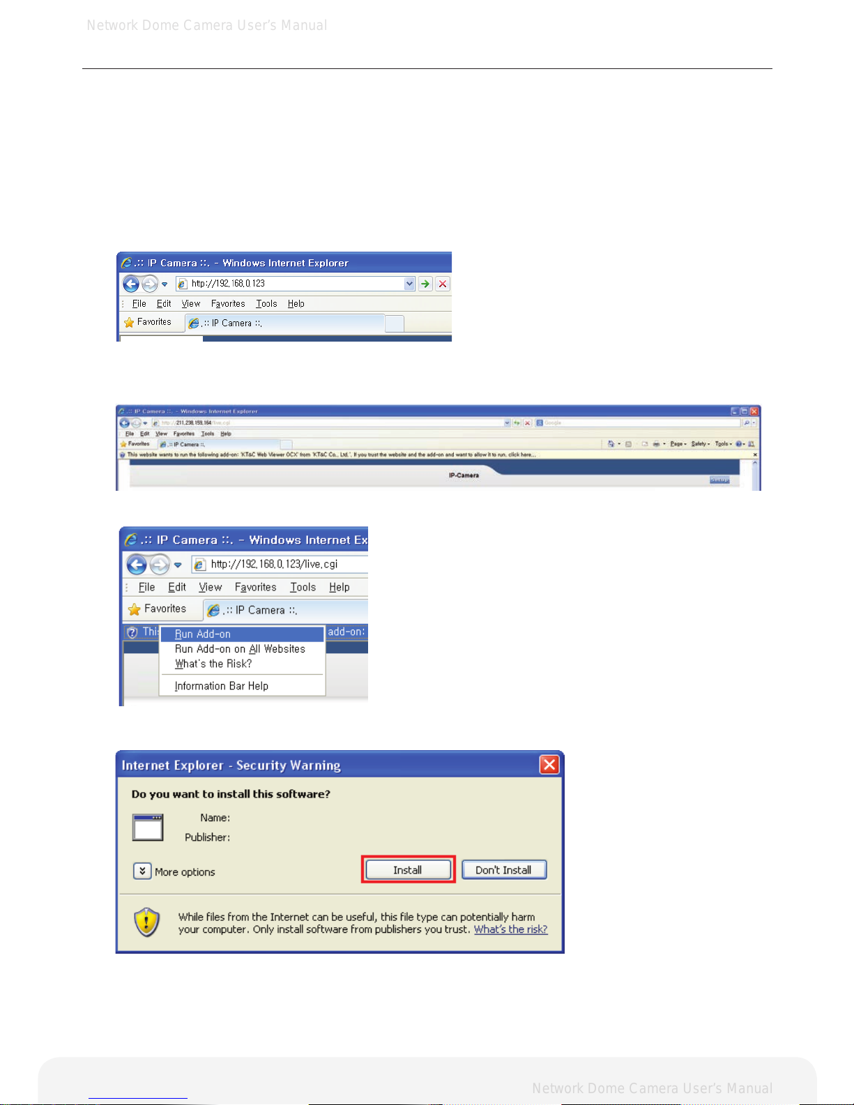
Start your browser
(when you rst run ActiveX to install, run an “IE as Administrator” on Window 7 or Vista))
Enter the IP address or host name of the Network Camera in the Address eld.
If you are accessing the Network Camera for the rst time, you will see the warning message as shown
below.
Click the warning message and select “Run Add-on” or “Install ActiveX Control…” etc.
Click “Install” to install the Web Viewer.
Page 10
Network Dome Camera User’s Manual
Network Dome Camera User’s Manual
10
Using the Network Camera
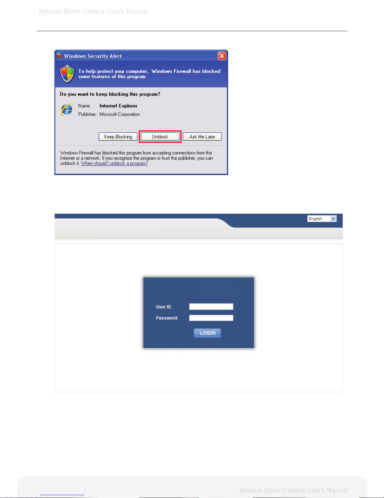
6.7.If the Windows Security Alert pop-up window appears, click the “Unblock” Button.
After installing the ActiveX Control, a Login page will be displayed. Enter the user ID and password.
Note: Default User ID and Password is [ID: admin, Password: admin]
IP CAMERA
IP CAMERA
Page 11
Network Dome Camera User’s Manual
Network Dome Camera User’s Manual
11
Using the Network Camera
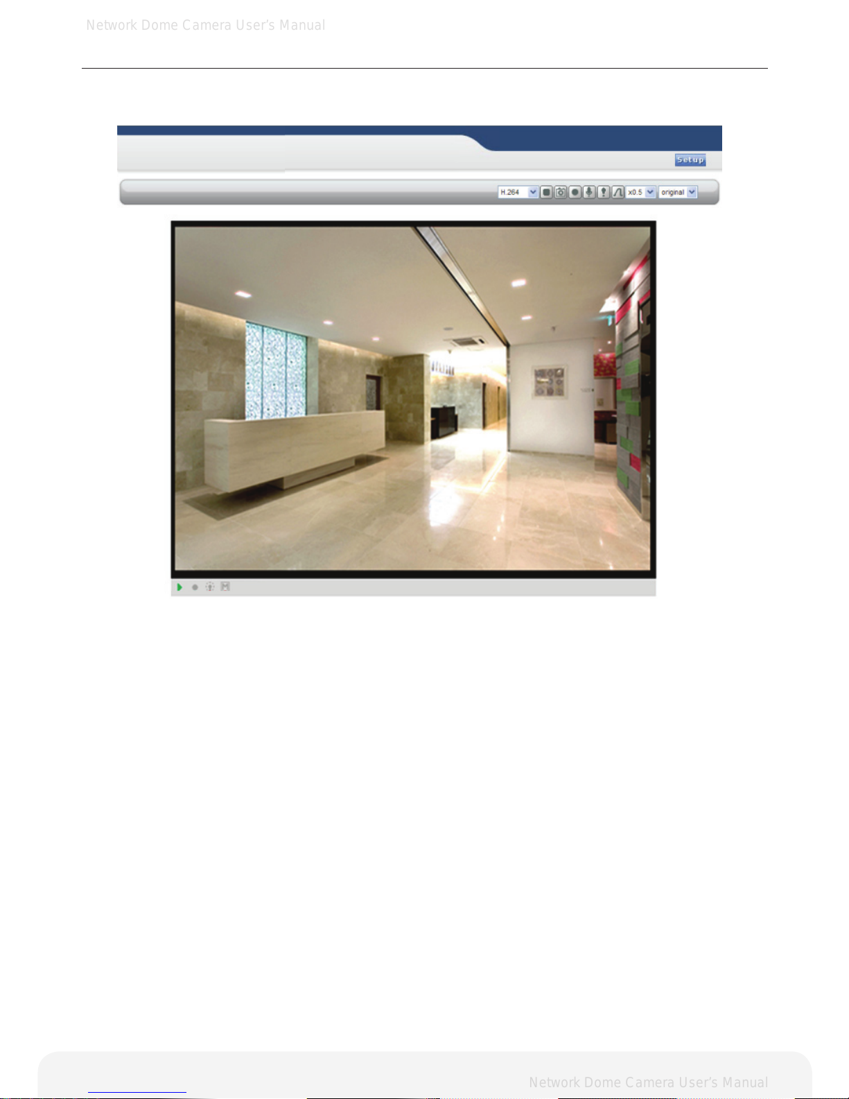
8. The video image will be displayed in your browser.
Important: To view streaming video in Microsoft Internet Explorer, you must set your browser to allow the
Web Viewer to be installed on your computer. This ActiveX component will be installed when you access
the camera for the rst time.
IP CAMERA
IP CAMERA
Page 12
Network Dome Camera User’s Manual
Network Dome Camera User’s Manual
Using the Network Camera
Live View page
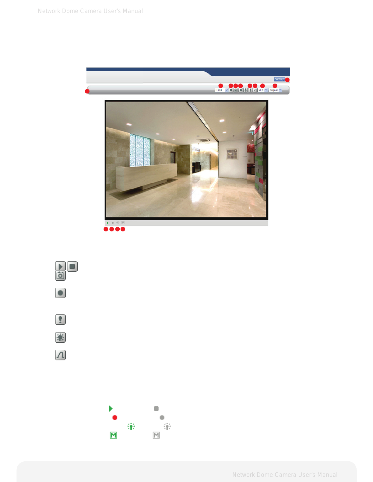
If the Network Camera has been customized on Setup>Advanced>Live View Layout, the buttons and
other items shown below may or may not be displayed on the Live View page. The following diagram
provides an overview of each available button.
1. Host Name – Displays the host name.
2. Video Format – The Video Format drop-down list allows the video format to change
instantly on the Live View page.
3.
Play/Stop – The Play/Stop button starts and stops the media stream.
4.
Snapshot – The Snapshot button takes a snapshot of the live image.
The target directory for saving snapshots are …/My document//Snapshots
5.
Record – The Record button is used to record the current video stream to the local hard drive.
The target directory for saving video clip are …/My document//Video
Note: Video recording will be terminated automatically after 5 minutes.
6.
Manual Trigger – The Manual Trigger button triggers an event directly from the Live View page.
Click this button to manually start the events instantly.
7.
Active/Inactive – Click this button to manually start and stop the device which is connected to
the digital output terminal, such as an alarm or light.
Pulse – Click this button to activate the digital output terminal for a dened period of time.
(e.g. to switch on a light for 10 seconds)
8. Viewer Magnication – The magnication drop-down list allows the video screen to amplify or
shrink in live view mode. (0.5x, 1x, 1.5x, 2x)
9. Setup – Click the button to congure Network Camera. Please refer to Conguring Network Camera.
10.Ratio – Resizing the aspect ratio to 16:9 or 4:3 is only possible with the H.264 video format.
11. Video Indicator –
- Streaming / - Stopped.
12. Record Indicator –
- Recording / - Stopped.
13. Alarm Output Indicator –
- Active / - Inactive.
14. Motion Indicator –
- detected / - Undetected.
IP CAMERA
IP CAMERA
12
1
2 3 4 5 6 7 8910
11 12 13 14
Page 13
Network Dome Camera User’s Manual
Network Dome Camera User’s Manual
IP CAMERA
IP CAMERA
13
Conguring the Network Camera
This section describes how to congure the Network Camera and is intended for:
• Administrators, who have unrestricted access to the entire Setup menu.
• Operators, who have access to the Video & Image and Event Conguration settings.
The Network Camera is congured from the Setup menu in a standard web browser.
Accessing the Setup menu
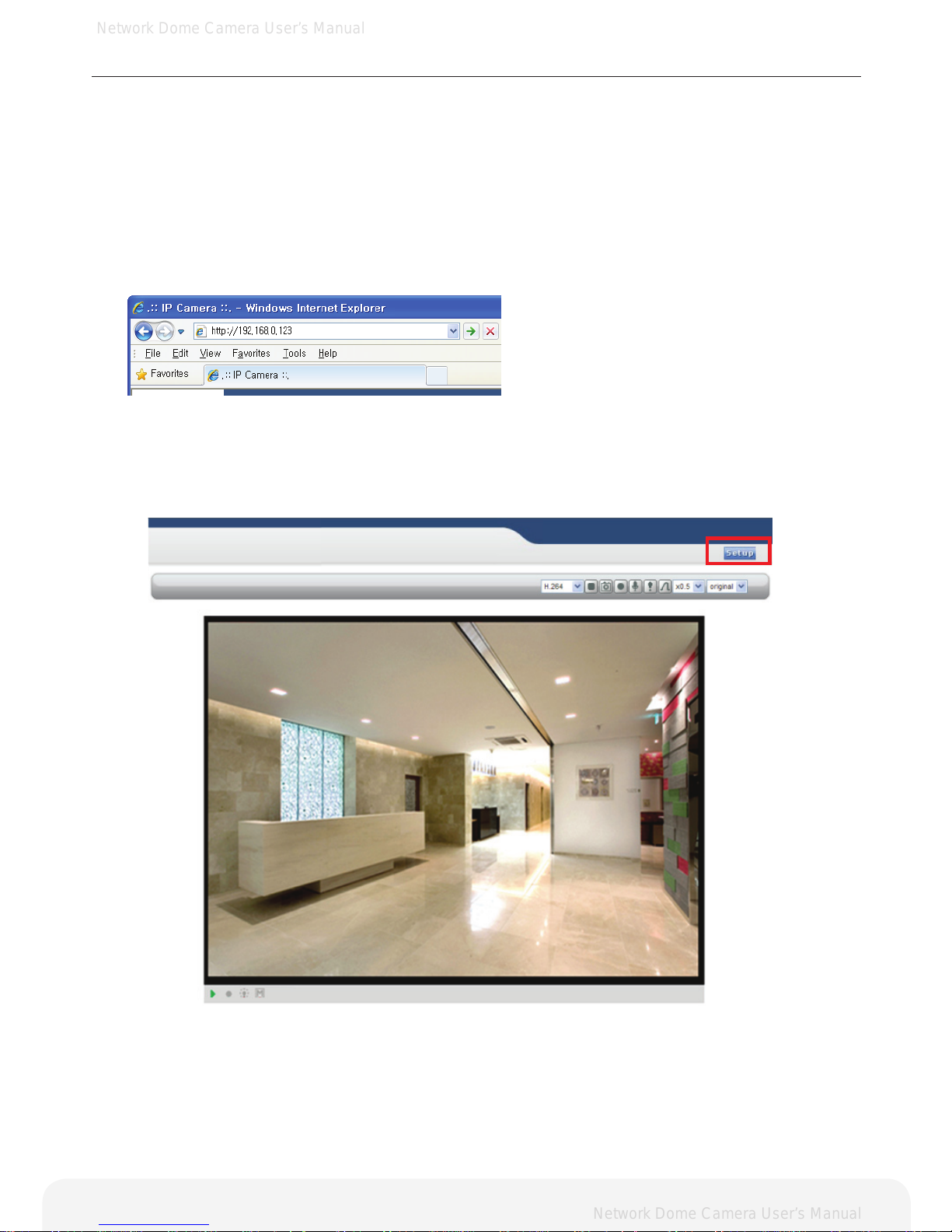
Follow the instructions below to access the Setup menu from a browser.
1. Start the browser and enter the IP address or host name of the Network Camera in the
location / address eld.
2. The Live View page is now being displayed. Click Setup to display the Setup menu.
Page 14
Network Dome Camera User’s Manual
Network Dome Camera User’s Manual
14
Conguring the Network Camera
Basic > Network
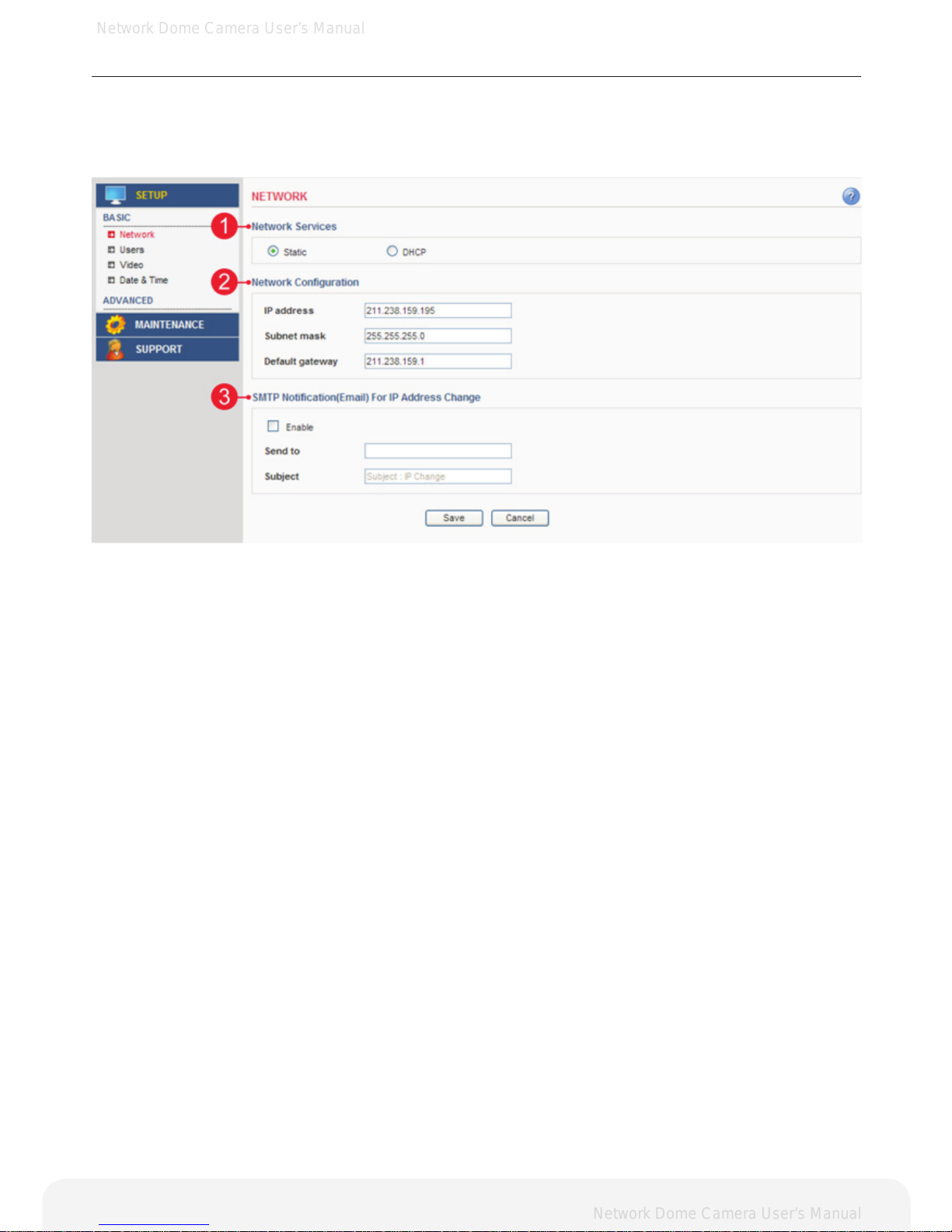
This section describes the basic network settings and SMTP notication. If the SMTP notication feature is
enabled, user can receive an IP change notication by e-mail when the IP address is changed by the DHCP
server.
1. Network Services
A. Static – Assigns a static IP address manually.
B. DHCP – Assigns a dynamic IP address automatically from the DHCP server on your network.
Important: DHCP should be enabled only if you are using the SMTP notication for the IP address change, or
if your DHCP server can update a DNS server, which allows you to access the Network Camera by the host
name. If DHCP is enabled and you cannot access the unit, then you may have to reset the unit to the factory
default and redo the installation again.
2. Network Conguration
A. IP Address – Specify a unique IP address for your Network Camera.
B. Subnet mask – Specify the mask of the Network Camera located subnet.
C. Default gateway – Specify the IP address of the default gateway (router) used for connecting devices
to the network.
3. SMTP Notication(E-mail) for IP Address Change
A. Send to – Enter the e-mail address of receiver.
B. Subject – Enter the e-mail subject as desired.
Important: Before using the SMTP Notication for IP address change, SMTP server has to be set on
Advanced > SMTP.
Note: DHCP is a protocol for automatic IP address assignment on a network. IP address assignment via
DHCP may lead to a situation where the IP address changes and you lose connection with the Network
Camera. Enable the SMTP Notication of IP address change to receive a notication from the Network
Camera when the IP address changes.
Page 15
Network Dome Camera User’s Manual
Network Dome Camera User’s Manual
15
Conguring the Network Camera
Basic > Users
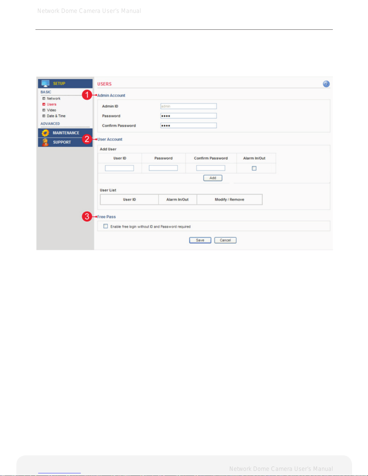
This section describes the administrator and user account settings. Each user can be congured to different
authority levels.
1. Admin Account
A. Admin ID – Enter the administrator ID.
B. Admin Password – Enter the administrator password.
Important: Factory default value is ID: admin, Password: admin.
2. User Account
A. Add User – Add a user account. Enter the user ID and Password. Each user can be congured to
a different level of authority for Alarm In/Out, PTZ, etc.
B. User List – Displays list of authorized user for the network camera. Click the modify button to modify
the authority. Click the remove button to erase the user account.
3. Free Pass
Free Pass means that anybody on the network can access the Network Camera and its images (but not the
Setup tools) from a browser without login in to the unit. To enable the feature, check the box to Enable Free
Pass.
Important: If this feature is enabled, all users can access the Live View page without a login process. If the
Network Camera is installed at an area needing privacy, this feature must be disabled.
Page 16
Network Dome Camera User’s Manual
Network Dome Camera User’s Manual
16
Conguring the Network Camera
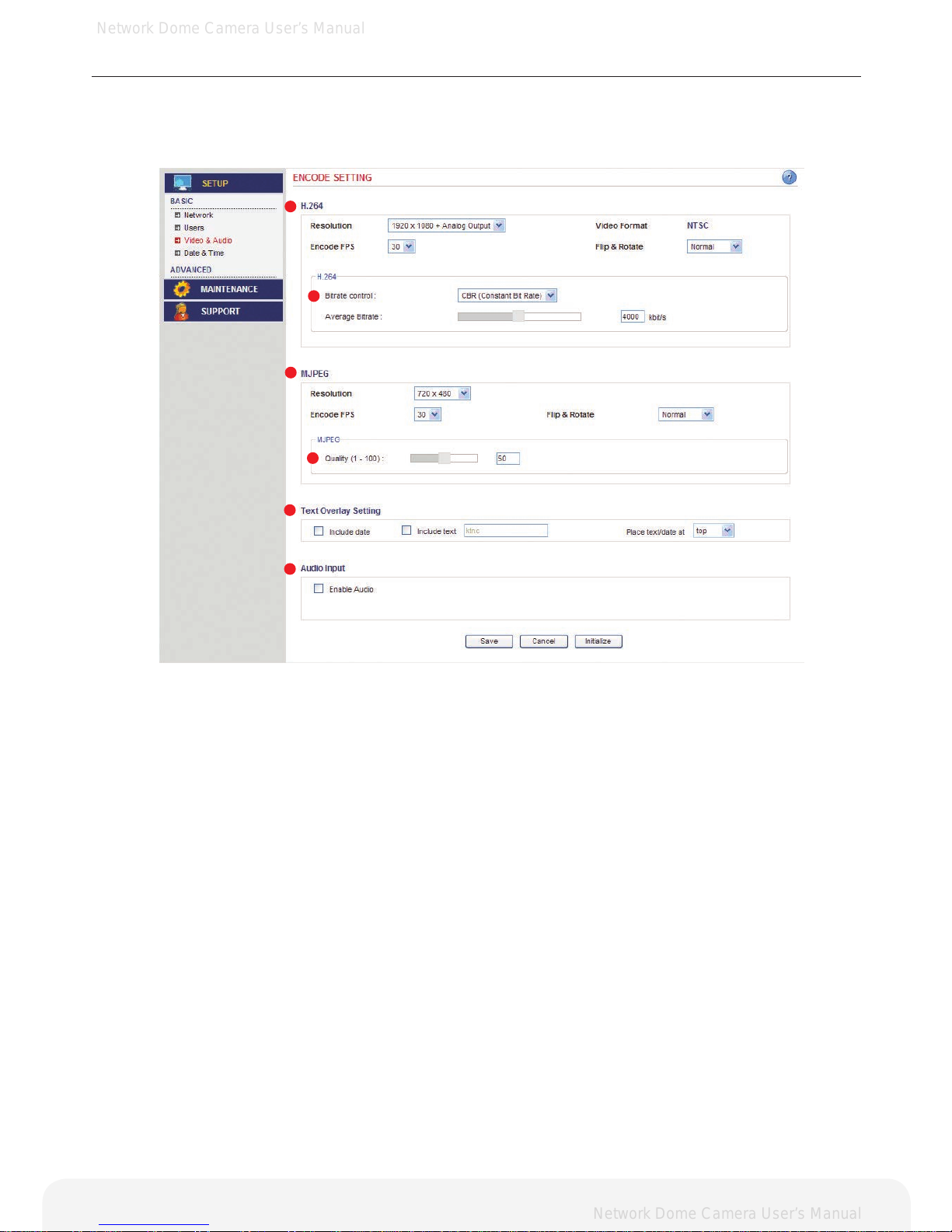
Basic > Video > Common
This section the basic settings for videos. NOTE: Audio output is not supported.
Important: These setting values will affect the original video and images.
1. H.264
A. Resolution – Select the resolution to use for the H.264 and JPEG image.
B. Video Format –The analog video format.
C. Maximum Frame rate - This feature is used to limit the frame rate. The frame rate can be set by selecting
values from the drop down list.
D. Flip & Rotate – Flip the picture.
2. Bit Rate Control
A. Variable bit rate (VBR) – Set the Network Camera to produce the variable bit rate H.264 video.
B. Constant bit rate (CBR) – Set the Network Camera to produce the constant bit rate H.264 video.
C. Target bit rate – The target bit rate can be adjusted in the range 256Kbps-8000Kbps.
High value improves video quality, but uses more bandwidth.
Note: When the variable bit rate is applied, the target bit rate will be a maximum bit rate of the VBR H.264 video. If the
constant bit rate is applied, the bit rate of CBR H.264 video will be xed to the target bit rate.
3. MJPEG
A. Resolution – Select the resolution to use for the H.264 and JPEG image.
B. Maximum Frame rate - This feature is used to limit the frame rate. The frame rate can be set by selecting
values from the drop down list.
C. Flip & Rotate – Flip the picture.
4. MJPEG Quality
A. Quality – Changing the image quality affects the amount of bandwidth required.
High value improves image quality, but uses more bandwidth.
1
2
3
4
5
6
Page 17
Network Dome Camera User’s Manual
Network Dome Camera User’s Manual
17
Conguring the Network Camera
5. Text Overlay Settings
A. Include date – Includes date in the video image as congured.
B. Include time – Includes time in the video image as congured.
C. Include text –Enter your own text in the eld to overlay text in the video image.
Note: The maximum number of characters in this eld is 17 characters. You can see the whole text (max 17 characters) in
the video image. But if you use 320x240 resolution, you can only view up to 2 characters.
D. Place text/date/time at – Select top or bottom position to display text, date, time.
6. Audio Settings
A. Enable Audio – Audio output is not supported.
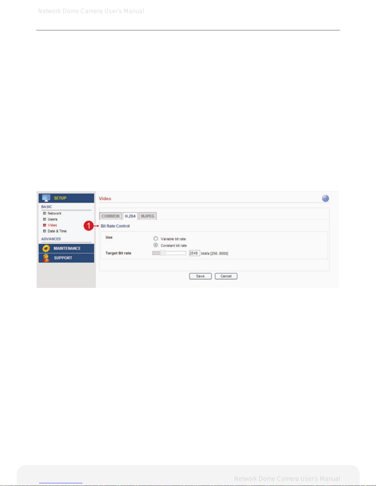
Basic > Video > H.264
This section describes the basic setting for the H.264.
Note: These setting values do not apply to the MJPEG video.
1. Bit Rate Control
A. Variable bit rate (VBR) – Set the Network Camera to produce the variable bit rate H.264 video.
B. Constant bit rate (CBR) – Set the Network Camera to produce the constant bit rate H.264 video.
C. Target bit rate – The target bit rate can be adjusted in the range 256Kbps-8000Kbps.
High value improves video quality, but uses more bandwidth.
Note: When the variable bit rate is applied, the target bit rate will be a maximum bit rate of the VBR H.264 video.
If the constant bit rate is applied, the bit rate of CBR H.264 video will be xed to the target bit rate.
Page 18
Network Dome Camera User’s Manual
Network Dome Camera User’s Manual
18
Conguring the Network Camera
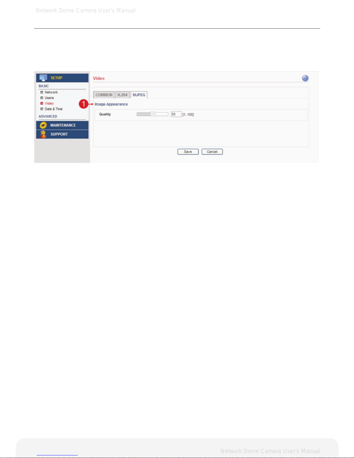
Basic > Video > MJPEG
This section describes basic setting for MJPEG video.
Note: These setting values do not apply to H.246 video.
1. Image Appearance
Quality – Changing the image quality affects the amount of bandwidth required.
High value improves image quality, but uses more bandwidth.
Page 19
Network Dome Camera User’s Manual
Network Dome Camera User’s Manual
19
Conguring the Network Camera
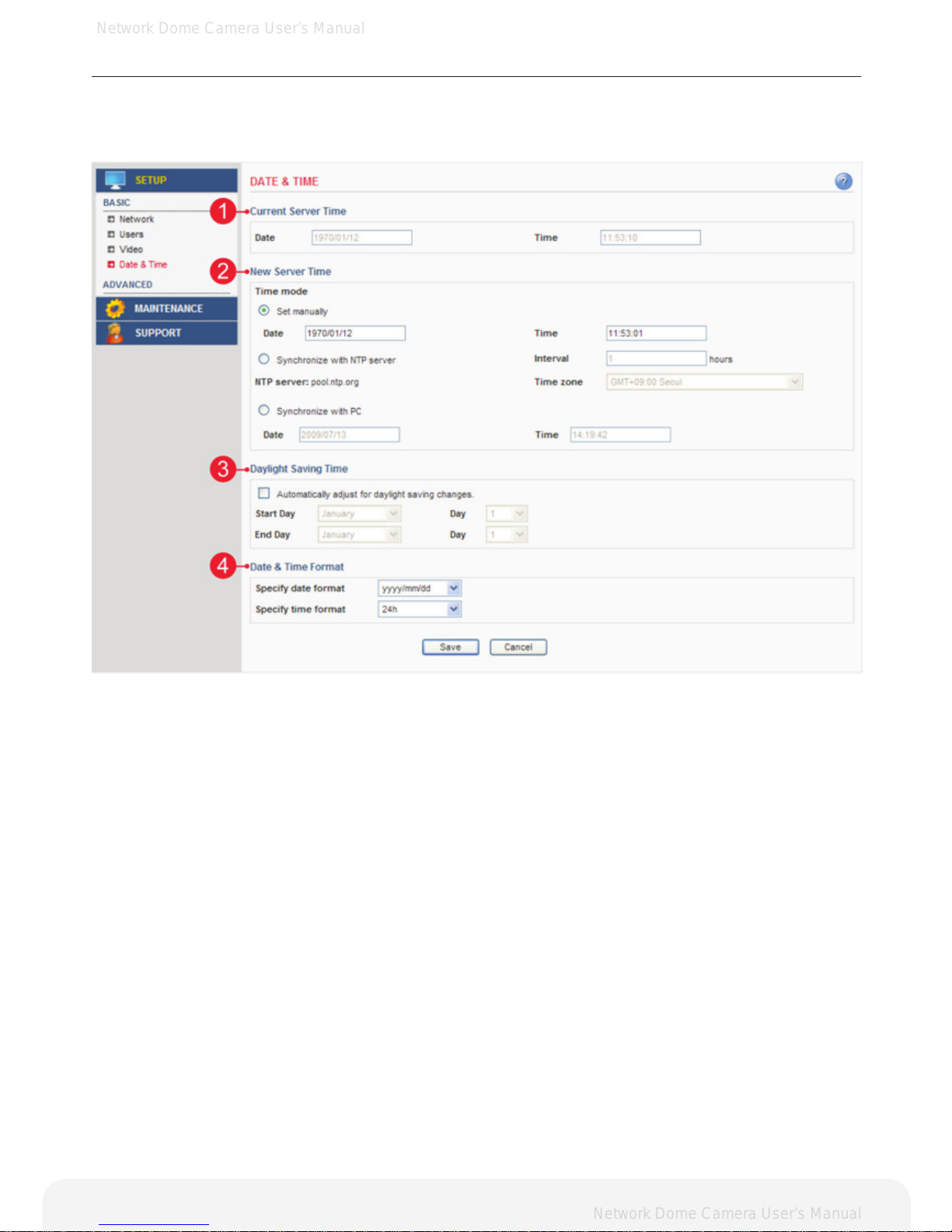
Basic > Date & Time
This section describes about the date and time settings.
1. Current Server Time
A. Date – Displays current date of Network Camera.
B. Time – Displays current time of Network Camera.
2. New Server Time
A. Set manually – Using this option allows you to enter the time and date manually.
B. Synchronize with NTP server – The Network Camera will sync the time with a NTP server.
The NTP server’s IP address or host name is specied in the Setup>Advanced Network>NTP Setting
C. Synchronize with PC – sync the time with a local computer.
3. Daylight Saving Time
A. Enable this feature to adjust automatically to the daylight savings time.
B. Set the start and end date.
4. Date & Time Format
This format will be used when displaying the date and time as overlay in the video image.
Note: As a real-time clock(RTC) is not supported, you must always set the current time after
turning on the device.
Page 20
Network Dome Camera User’s Manual
Network Dome Camera User’s Manual
20
Conguring the Network Camera
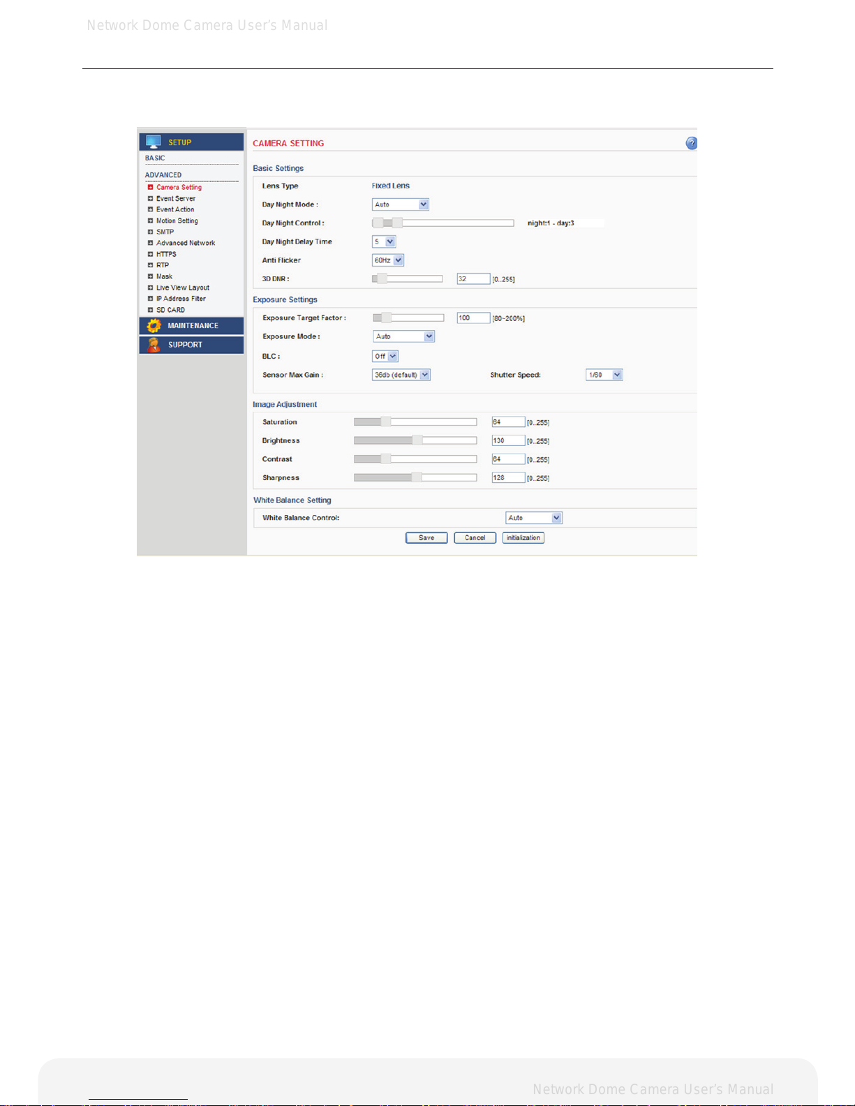
Advanced > Camera Setting
This section describes the advanced settings of the camera.
1. Basic Settings
A. Lens Type – The camera lens type.
B. Day and Night Mode – The day and night mode can be selected from the drop down list.
Auto – the camera will automatically switch between IR cut lter On and Off,
according to the current lighting conditions.
Color – the ip camera will always stay in color mode.
Black and White – This camera will be able to “see” infrared light, e.g. at night.,
thus making the image clearer.
C. Day Night Control – Adjust day and night lux level.
D. Day Night Delay Time – Adjust day and night delay time.
E. Anti Flicker – This setting is used to remove 50/60 Hz icker.
F. Digital Noise Reduction – The digital noise reduction can help depress noise under low light situation
but also blur some of the image detail. So it is better to set this value higher
under low light situation, and set it lower under good light condition.
2. Exposure Setting
A. Exposure Target Factor – Adjust the exposure target.
B. Exposure Mode – The camera’s exposure mode can be set to auto or manual by selecting Auto/Manual.
C. Auto – The ip camera will adjust the exposure automatically.
D. Manual – The exposure in the ip camera can be controlled manually by Max gain and shutter speed.
E. Back Light Compensation - Backlight compensation makes the subject appear clearer when the image
background is too bright, or the subject is too dark.
3. Image Adjustment
A. Saturation – Select an appropriate level by entering a value in the range between 0-255.
Lower values mean less color saturation and the value 255 gives maximum color saturation.
B. Brightness – The image brightness can be adjusted in the range between 0-255,
where a higher value produces a brighter image.
C. Contrast – The image contrast can be adjusted in the range between 0-255,
where a higher value produces a high contrasted image.
D. Sharpness – The image sharpness can be adjusted by selecting values,
where a higher value produces a sharper image.
4. White Balance Setting
A. White Balance – The image quality can be modied by selecting one of the white balance modes.
Page 21
Network Dome Camera User’s Manual
Network Dome Camera User’s Manual
21
Conguring the Network Camera
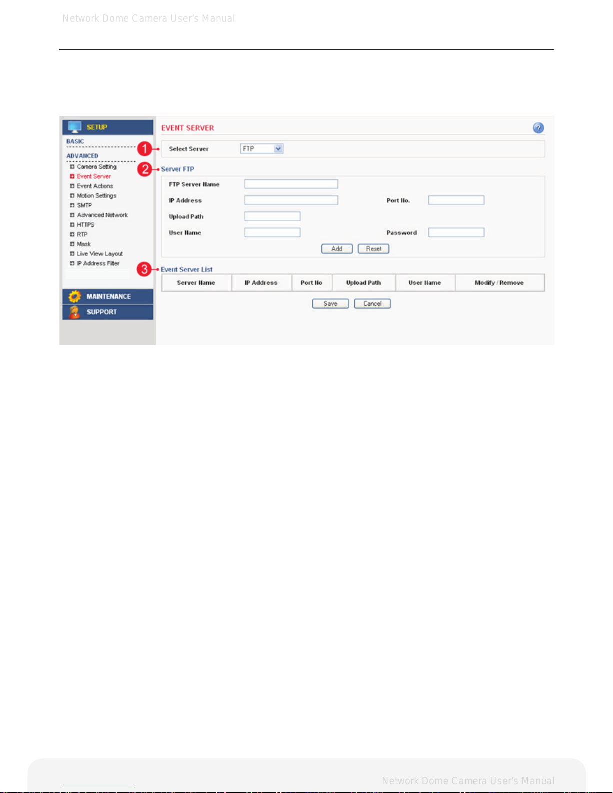
Advanced > Event Server
This section describes conguring the event server used in the event action section.
1. Select Server
A. Select the server type to congure. Conguration is only available for FTP servers.
2. Server FTP
- FTP Server Name – Enter the any descriptive name.
- IP Address – Enter the server’s IP address or host name.
Important: DNS server must be specied in the Setup>Advanced>Advanced network if you are
using a host name.
- Port No. – Enter the port number used by the FTP server. The default is 21.
- Upload Path – Specify the path to the directory where the uploaded images will be stored.
Note that a directory must be created in the FTP server before using this feature.
- User Name – Enter the User ID.
- Password – Enter the Password.
3. Event Server List
- Display all of the congured servers. Click modify button to modify setting values.
Click remove button to erase the event server.
Note: A total of 3 event servers can be congured.
Page 22
Network Dome Camera User’s Manual
Network Dome Camera User’s Manual
22
Conguring the Network Camera
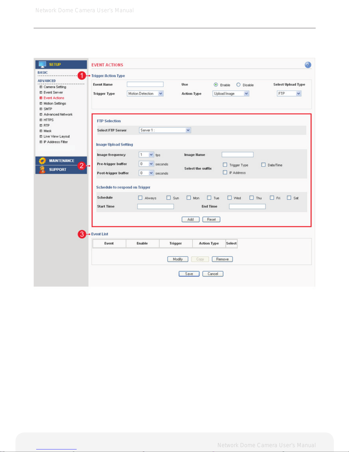
Advanced > Event Actions
This section describes how to congure the Network Camera for event handling. Various actions can be
congured to run when certain types of event occur.
1. Trigger / Action Type
Denes the trigger type or action type.
2. Action Conguration
Congures parameters of event action describing how and when the Network Camera is going to
perform the certain actions.
3. Event List
Displays all of the congured actions. Click the modify button to modify the setting values.
Click the remove button to erase the event action.
Page 23
Network Dome Camera User’s Manual
Network Dome Camera User’s Manual
23
Conguring the Network Camera
Prepare to congure event action
Event Servers are used for receiving uploaded image les and/or notication messages. To set up an Event
server for your Network Camera, go to Setup > Advanced > Event Server or Setup > Advanced > SMTP
and enter the required information according to the selected server type.
Note: When High image resolution and/or lower compression levels is used for uploading images to FTP
server, SMTP server, individual images may be missing.
If this occurs, Lower image resolution and/or lower compression levels must be used for seamless uploading.
Server Type Purpose Information required
FTP Server Receives uploaded images - Descriptive name of your choice
- User Name and Password (to FTP server)
- Upload path
- Port number
E-mail (SMTP) Receives uploaded images
Receives notication messages
- Descriptive name of your choice
- User Name and Password (to SMTP server)
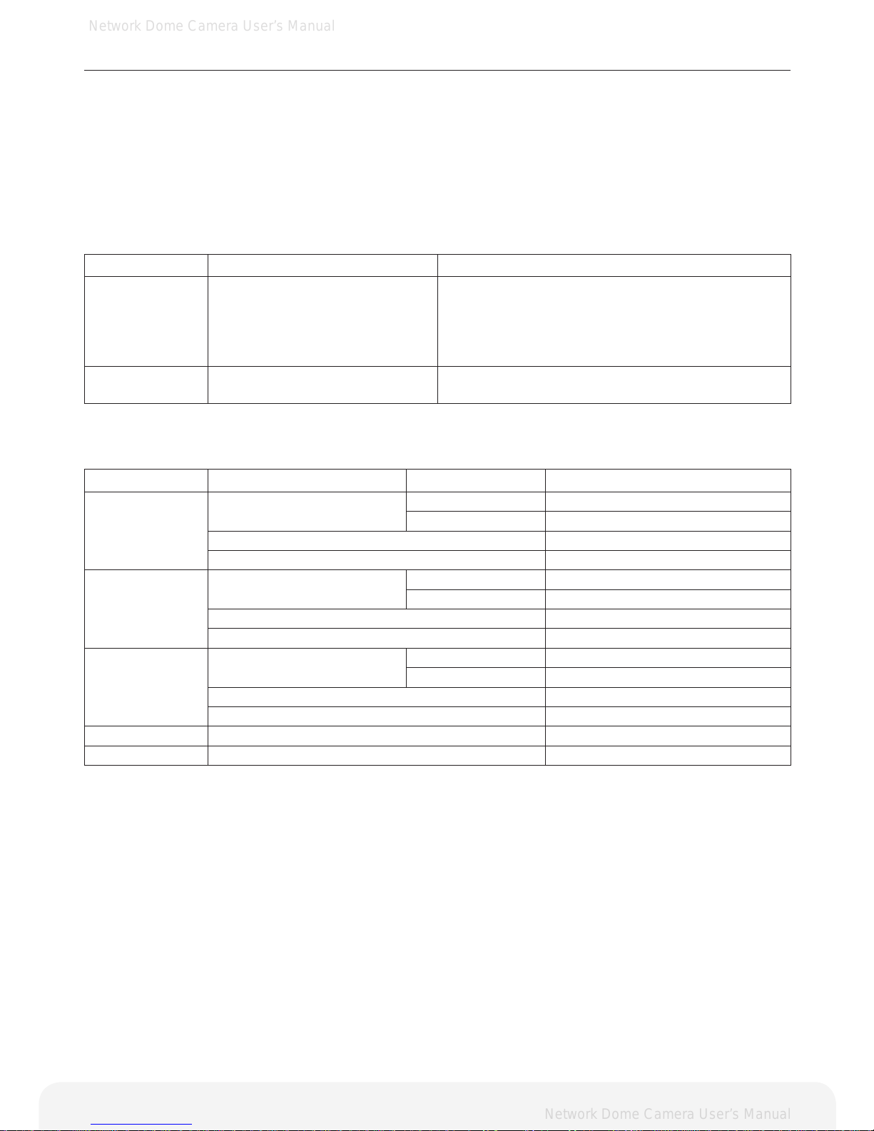
Variation of event action conguration
Trigger Type Action Type Upload Type Consequence
Motion detection Upload image FTP Upload images to FTP server
E-mail Upload images via E-mail.
Activate output Activate digital output
E-mail notication Send a notication message
Sensor in Upload image FTP Upload images to FTP server
E-mail Upload images via E-mail.
Activate output Activate digital output
E-mail notication Send a notication message
Manual Trigger Upload image FTP Upload images to FTP server
E-mail Upload images via E-mail.
Activate output Activate digital output
E-mail notication Send a notication message
Network Fail Activate Output Activate digital output.
Reboot E-mail notication Send a notication message
Page 24
Network Dome Camera User’s Manual
Network Dome Camera User’s Manual
Conguring the Network Camera
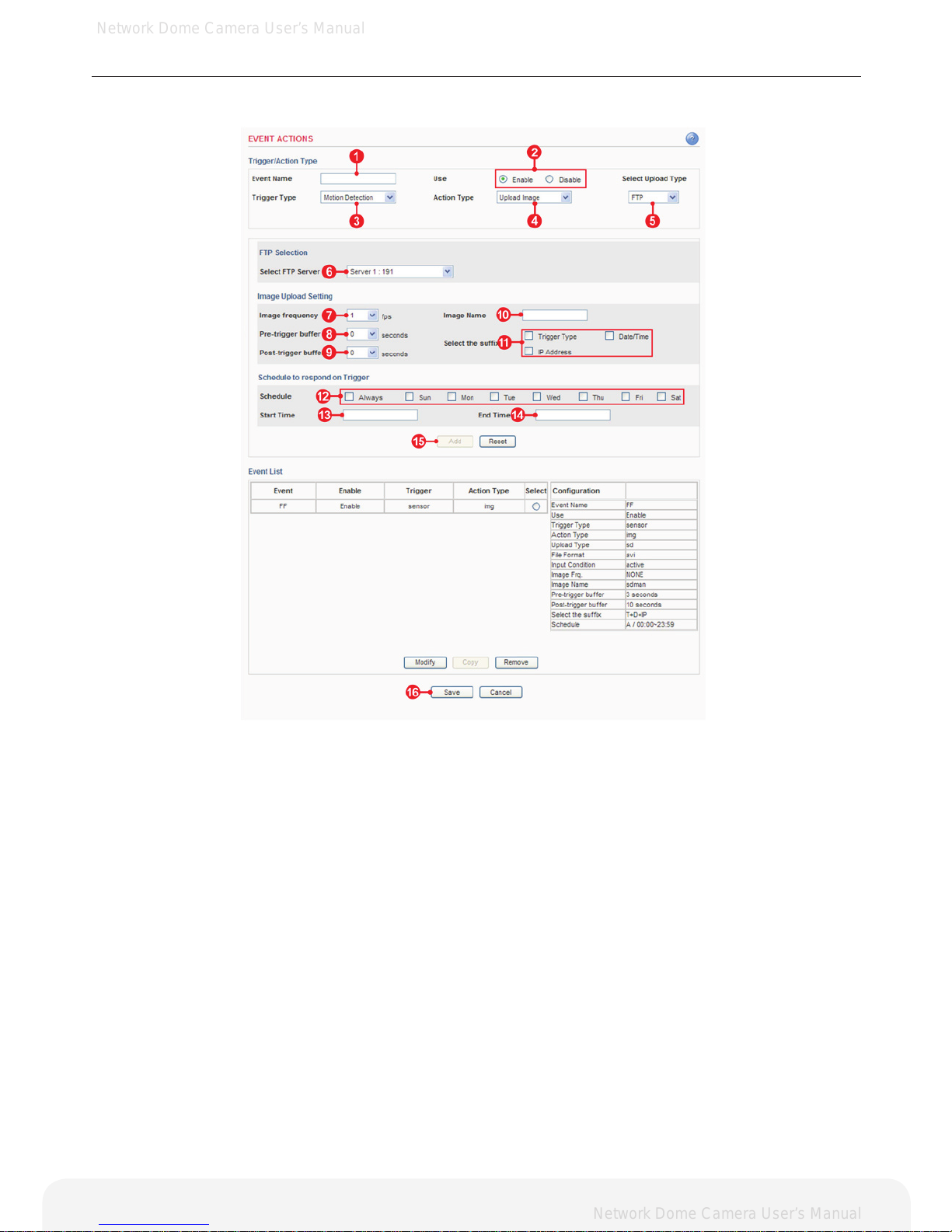
Action configuration for [Motion Detection + Upload Image + FTP]
1. Enter a descriptive event name.
2. Select the enable
3. Select the trigger type to motion detection.
4. Select the action type to upload image.
5. Select the upload type to FTP.
6. Select the FTP server that will receive uploaded image files.
7. Select the image frequency. (frame per second)
8. Select the pre-trigger buffer.
9. Select the post-trigger buffer.
10. Enter a descriptive image name.
11. Select the suffix of image name.
12. Select the schedule by a day of the week.
13. Enter the start time in a 24hour format.
14. Enter the end time in a 24hour format.
15. Click the Add button to add configuration on the event list.
16. Click the Save button to save configuration.
Note: Pre-trigger buffer - A pre-trigger buffer contains images/video from the time immediately preceding the
trigger. These are stored internally in the camera. This buffer can be very useful
when checking to see what caused the trigger.
Post-trigger buffer - This function is the counterpart to the pre-trigger buffer described above and contains
images/video from the time immediately after the trigger.
Important: Image frequency and Pre-trigger buffer can be changed depending on the settings of
JPEG frame rate.
24
Page 25
Network Dome Camera User’s Manual
Network Dome Camera User’s Manual
25
Conguring the Network Camera
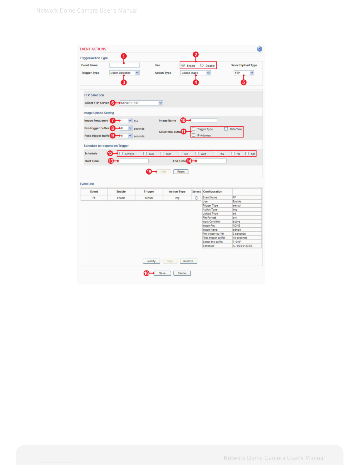
Action configuration for [Motion Detection + Upload Image + E-mail]
1. Enter a descriptive event name.
2. Select the enable
3. Select the trigger type to motion detection.
4. Select the action type to upload image.
5. Select the upload type to FTP.
6. Select the FTP server that will receive uploaded image files.
7. Select the image frequency. (frame per second)
8. Select the pre-trigger buffer.
9. Select the post-trigger buffer.
10. Enter a descriptive image name.
11. Select the suffix of image name.
12. Select the schedule by a day of the week.
13. Enter the start time in a 24hour format.
14. Enter the end time in a 24hour format.
15. Click the Add button to add configuration on the event list.
16. Click the Save button to save configuration.
Note: Pre-trigger buffer - A pre-trigger buffer contains images/video from the time immediately preceding the
trigger. These are stored internally in the camera. This buffer can be very useful when checking to see
what caused the trigger.
Post-trigger buffer - This function is the counterpart to the pre-trigger buffer described above and
contains images/video from the time immediately after the trigger.
Important: Image frequency and Pre-trigger buffer can be changed depending on the settings of
JPEG frame rate.
Page 26
Network Dome Camera User’s Manual
Network Dome Camera User’s Manual
26
Conguring the Network Camera
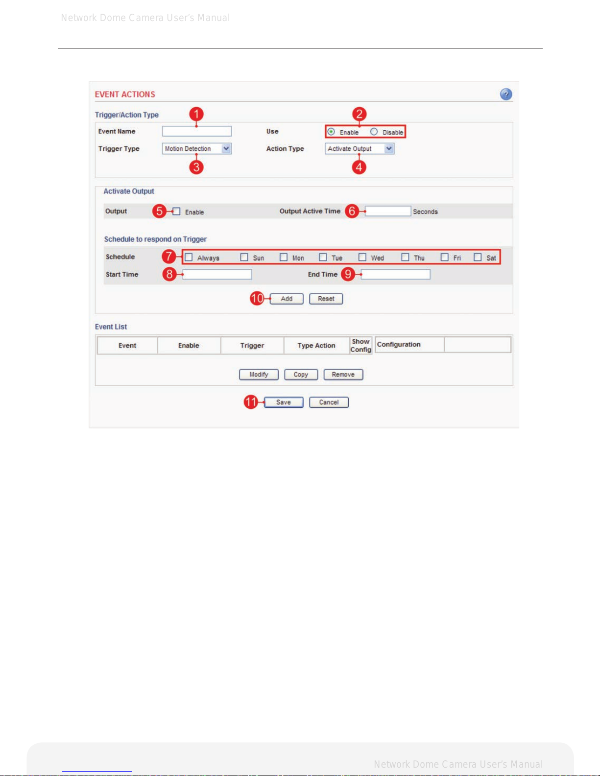
Action configuration for [Motion Detection + Activate output]
1. Enter a descriptive event name.
2. Select the enable.
3. Select the trigger type to motion detection.
4. Select the action type to activate output.
5. Check the enable.
6. Enter the output active time.
7. Select the schedule by a day of the week.
8. Enter the start time in a 24hour format.
9. Enter the end time in a 24hour format.
10. Click the Add button to add configuration on the event list.
11. Click the Save button to save configuration.
Page 27
Network Dome Camera User’s Manual
Network Dome Camera User’s Manual
27
Conguring the Network Camera
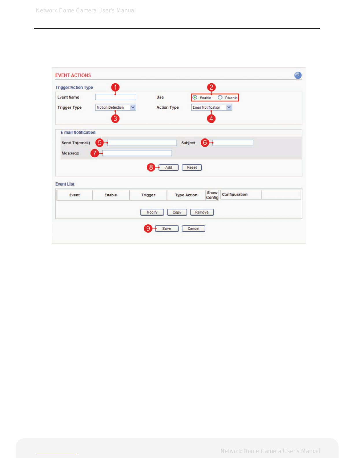
Action configuration for [Motion Detection + E-mail Notification]
1. Enter a descriptive event name.
2. Select the enable.
3. Select the trigger type to motion detection.
4. Select the action type to e-mail notification.
5. Enter the e-mail address which receives notification.
6. Enter a descriptive subject.
7. Enter a descriptive message.
8. Click the Add button to add configuration on the event list.
9. Click the Save button to save configuration.
Page 28
Network Dome Camera User’s Manual
Network Dome Camera User’s Manual
28
Conguring the Network Camera
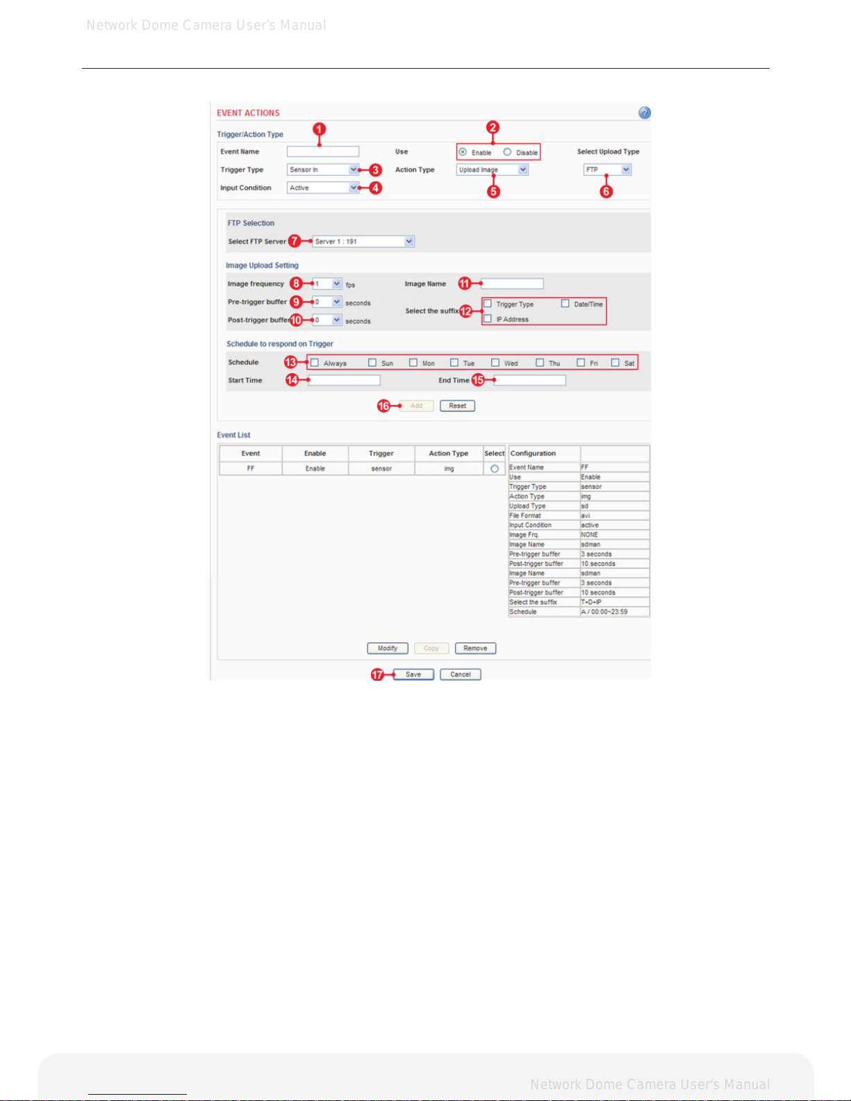
Action configuration for [Sensor Input + Upload Image + FTP]
1. Enter a descriptive event name.
2. Select the enable.
3. Select the trigger type to sensor in.
4. Select the input condition
A. Active – Event will trigger when the input condition is active.
B. Inactive – Event will trigger when the input condition is inactive.
C. Change – Event will trigger when input condition is changed.
5. Select the action type to upload image.
6. Select the upload type to FTP.
7. Select the FTP server that receives uploaded image files.
8. Select the image frequency. (frame per second)
9. Select the pre-trigger buffer.
10. Select the post-trigger buffer.
11. Enter a descriptive image name.
12. Select the suffix of image name.
13. Select the schedule by a day of the week.
14. Enter the start time in a 24hour format.
15. Enter the end time in a 24hour format.
16. Click the Add button to add configuration on the event list.
17. Click the Save button to save configuration.
Note: Pre-trigger buffer - A pre-trigger buffer contains images/video from the time immediately preceding the
trigger. These are stored internally in the camera. This buffer can be very useful when checking to see what
caused the trigger.
Post-trigger buffer - This function is the counterpart to the pre-trigger buffer described above and contains
images/video from the time immediately after the trigger.
Important: Image frequency and Pre-trigger buffer can be changed depending on
the settings of JPEG frame rate.
Page 29
Network Dome Camera User’s Manual
Network Dome Camera User’s Manual
29
Conguring the Network Camera
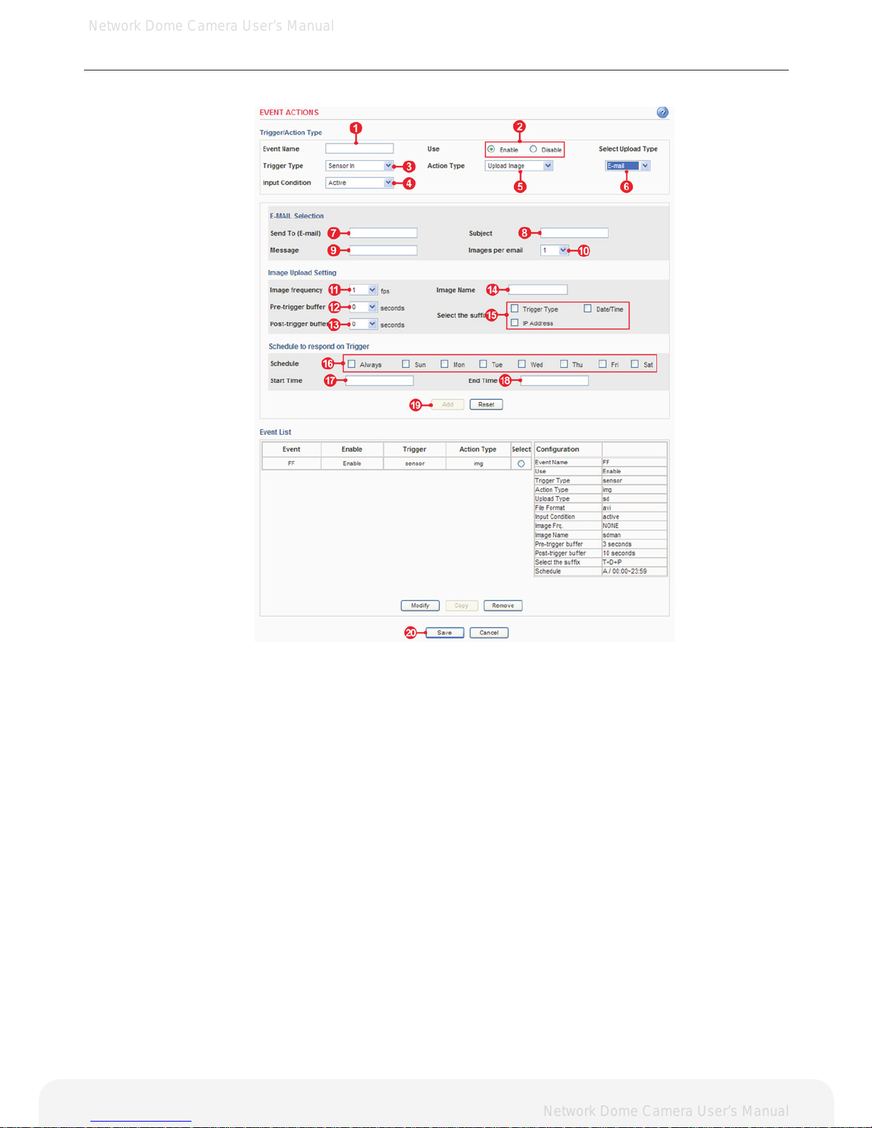
Action configuration for [Sensor Input + Upload Image + E-mail]
1. Enter a descriptive event name.
2. Select the enable.
3. Select the trigger type to sensor in.
4. Select the input condition
A. Active – Event will trigger when input
condition is active.
B. Inactive – Event will trigger when input
condition is inactive.
C. Change – Event will trigger when input
condition is changed
5. Select the action type to upload image.
6. Select upload type to E-mail.
7. Enter the e-mail address which receives
image les.
8. Enter a descriptive subject.
9. Enter a descriptive message.
10. Select the number of images.
11. Select the image frequency. (frame per second)
12. Select the pre-trigger buffer.
13. Select the post-trigger buffer.
14. Enter a descriptive image name.
15. Select the sufx of image name.
16. Select the schedule by a day of the week.
17. Enter the start time in a 24hour format.
18. Enter the end time in a 24hour format.
19. Click the Add button to add conguration
on the event list.
20. Click the Save button to save conguration.
Note: Pre-trigger buffer - A pre-trigger buffer contains images/video from the time immediately preceding the
trigger. These are stored internally in the camera. This buffer can be very useful when checking to see what
caused the trigger.
Post-trigger buffer - This function is the counterpart to the pre-trigger buffer described above and contains
images/video from the time immediately after the trigger.
Important: Image frequency and Pre-trigger buffer can be changed depending on the settings
of JPEG frame rate.
Page 30
Network Dome Camera User’s Manual
Network Dome Camera User’s Manual
30
Conguring the Network Camera
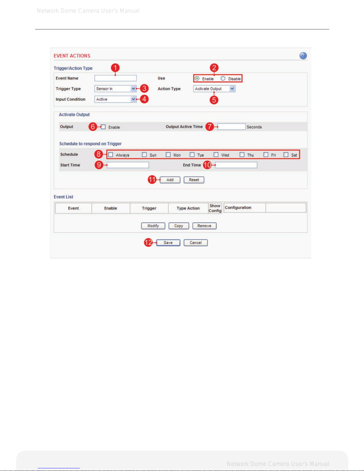
Action configuration for [Sensor Input + Activate Output]
1. Enter a descriptive event name.
2. Select the enable.
3. Select the trigger type to sensor in.
4. Select the input condition
A. Active – Event will trigger when input condition is active.
B. Inactive – Event will trigger when input condition is inactive.
C. Change – Event will trigger when input condition is changed.
5. Select the action type to activate output.
6. Check the enable.
7. Enter the output active time.
8. Select the schedule by a day of the week.
9. Enter the start time in a 24hour format.
10. Enter the end time in a 24hour format.
11. Click the Add button to add configuration on the event list.
12. Click the Save button to save configuration.
Page 31
Network Dome Camera User’s Manual
Network Dome Camera User’s Manual
31
Conguring the Network Camera
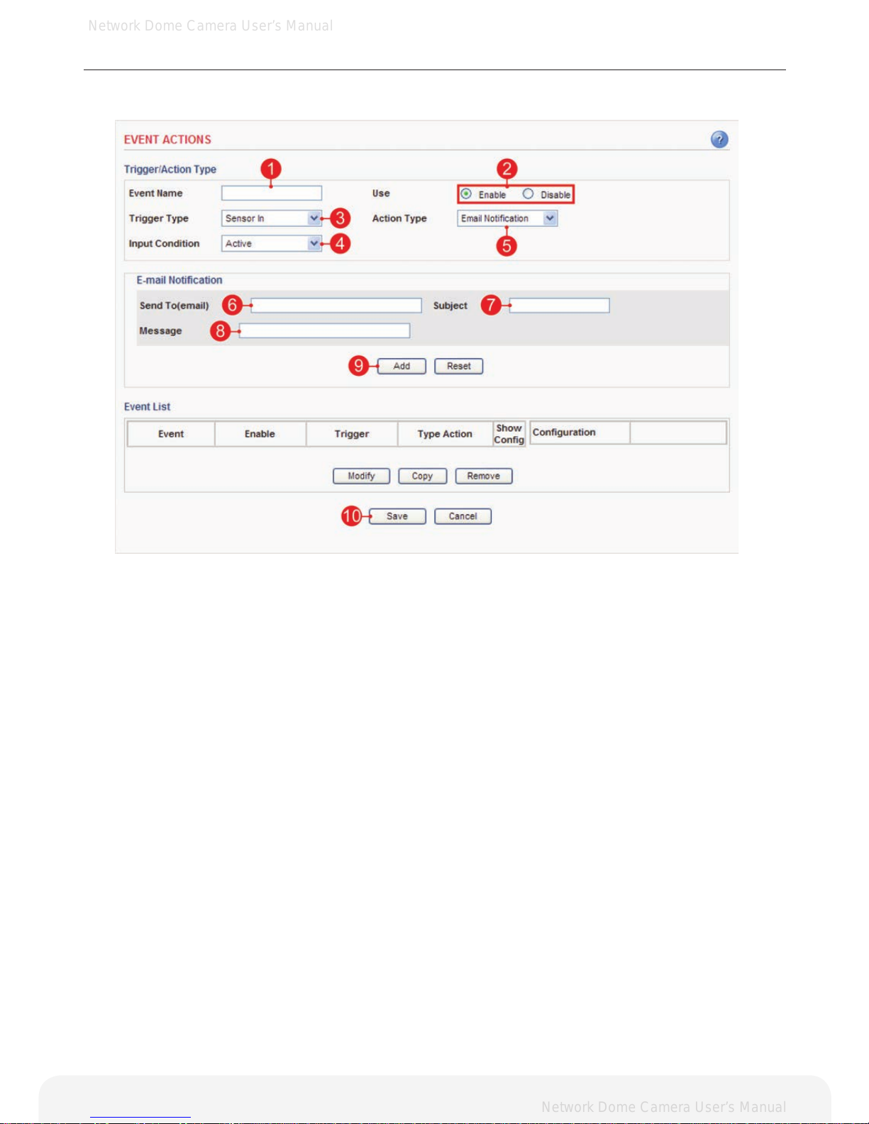
Action configuration for [Sensor Input + E-mail Notification]
1. Enter a descriptive event name.
2. Select the enable.
3. Select the trigger type to sensor in.
4. Select the input condition
A. Active – Event will trigger when input condition is active.
B. Inactive – Event will trigger when input condition is inactive.
C. Change – Event will trigger when input condition is changed.
5. Select the action type to e-mail notification.
6. Enter the e-mail address which receives notification.
7. Enter a descriptive subject.
8. Enter a descriptive message.
9. Click the Add button to add configuration on the event list.
10. Click the Save button to save configuration.
Page 32
Network Dome Camera User’s Manual
Network Dome Camera User’s Manual
32
Conguring the Network Camera
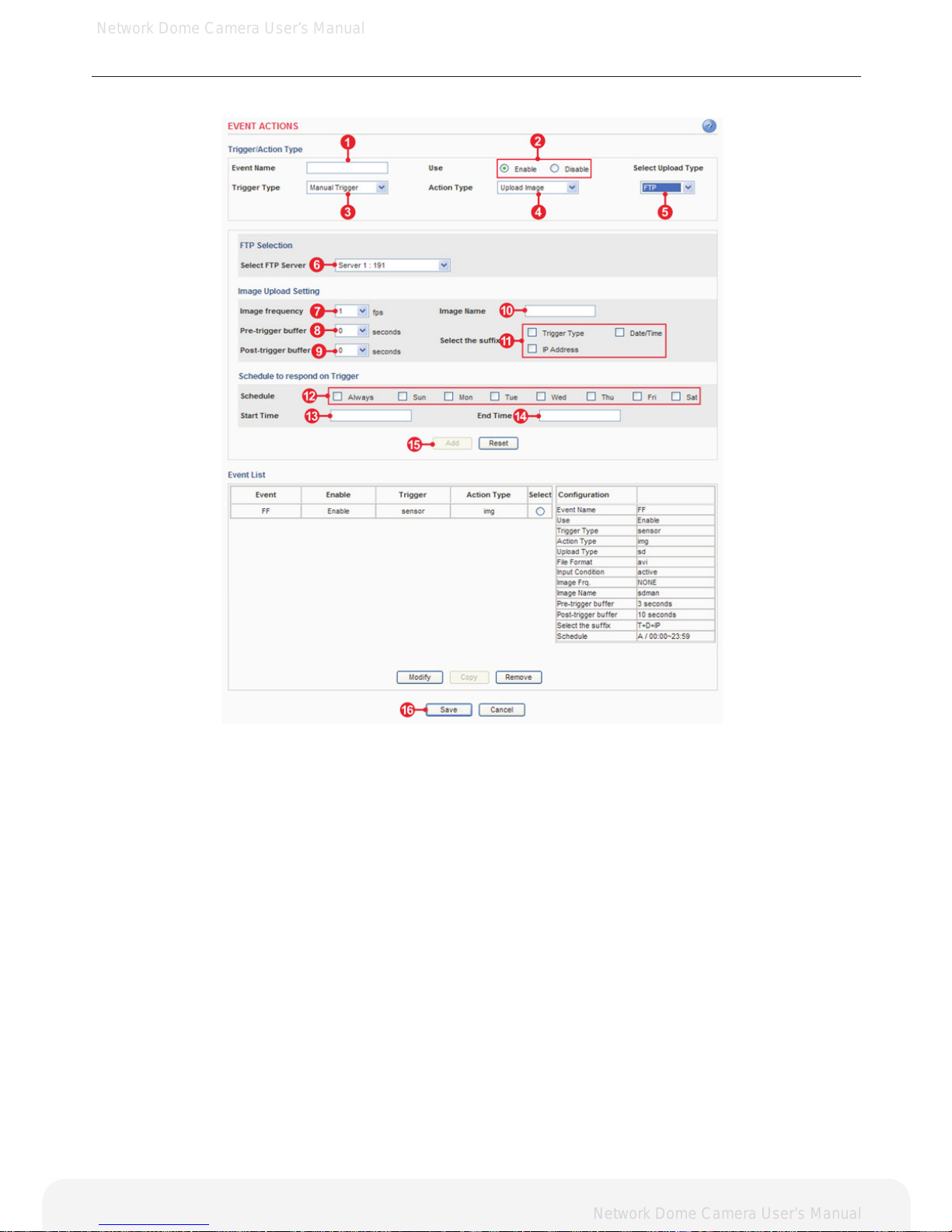
Action configuration for [Manual Trigger + Upload Image + FTP]
1. Enter a descriptive event name.
2. Select the enable.
3. Select the trigger type to manual trigger.
4. Select the action type to upload image.
5. Select the upload type to FTP.
6. Select the FTP server that receives uploaded image files.
7. Select the image frequency. (frame per second)
8. Select the pre-trigger buffer.
9. Select the post-trigger buffer.
10. Enter a descriptive image name.
11. Select the suffix of image name.
12. Select the schedule by a day of the week.
13. Enter the start time in a 24hour format.
14. Enter the end time in a 24hour format.
15. Click the Add button to add configuration on the event list.
16. Click the Save button to save configuration.
Note: Pre-trigger buffer - A pre-trigger buffer contains images/video from the time immediately preceding the
trigger. These are stored internally in the camera. This buffer can be very useful when checking to see what
caused the trigger.
Post-trigger buffer - This function is the counterpart to the pre-trigger buffer described above and contains
images/video from the time immediately after the trigger.
Important: Image frequency and pre-trigger buffer can be changed depending on the
settings of JPEG frame rate.
Page 33
Network Dome Camera User’s Manual
Network Dome Camera User’s Manual
33
Conguring the Network Camera
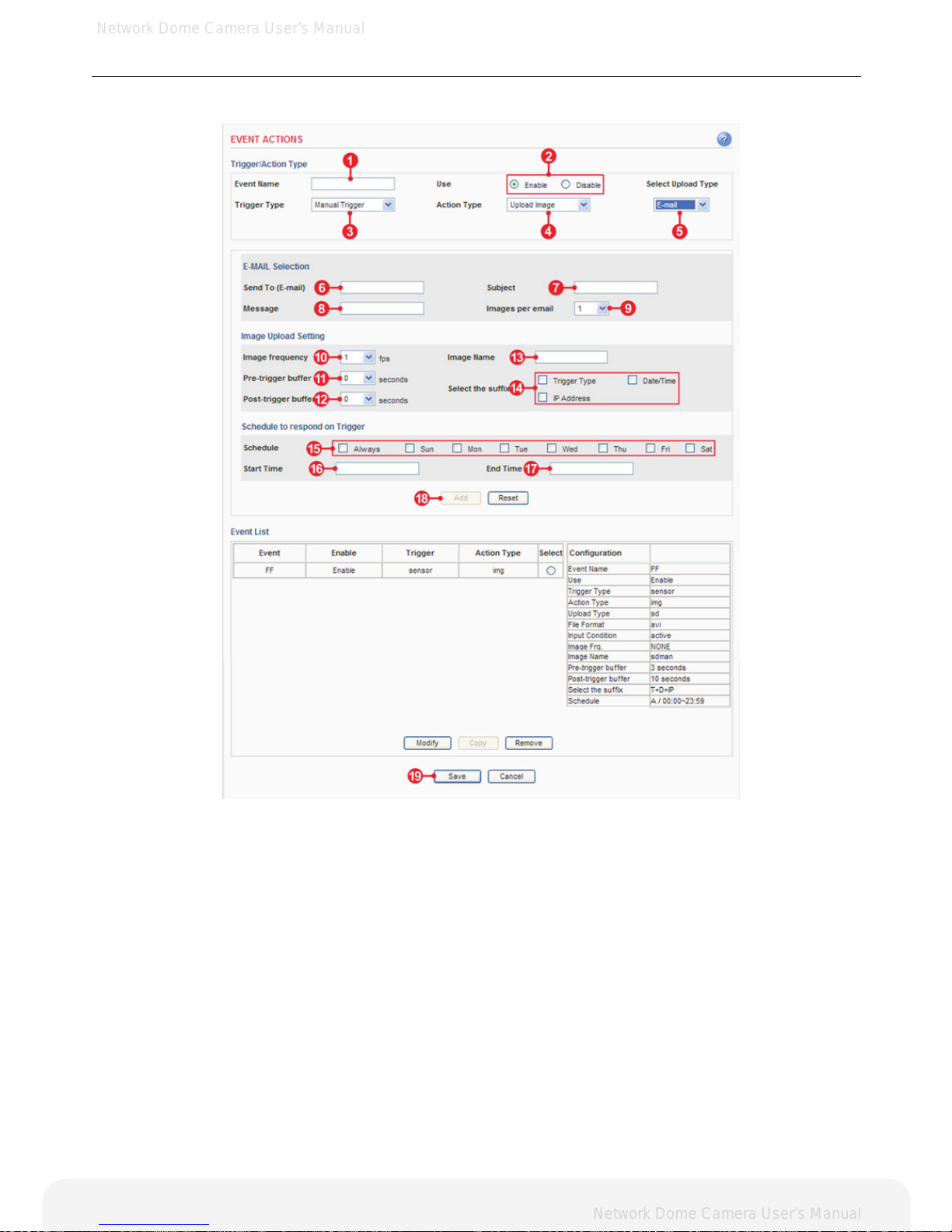
Action configuration for [Manual Trigger + Upload Image + E-mail]
1. Enter a descriptive event name.
2. Select the enable.
3. Select the trigger type to manual trigger.
4. Select the action type to upload image.
5. Select the upload type to E-mail.
6. Enter the e-mail address which receives
image files.
7. Enter a descriptive subject.
8. Enter a descriptive message.
9. Select the number of images.
10. Select the image frequency.
(frame per second)
11. Select pre-trigger buffer.
12. Select post-trigger buffer.
13. Enter a descriptive image name.
14. Select the suffix of image name.
15. Select the schedule by a day of the week.
16. Enter the start time in a 24hour format.
17. Enter the end time in a 24hour format.
18. Click the Add button to add configuration
on the event list.
19. Click the Save button to save configuration.
Note: Pre-trigger buffer - A pre-trigger buffer contains images/video from the time immediately preceding the
trigger. These are stored internally in the camera. This buffer can be very useful when checking to see what
caused the trigger.
Post-trigger buffer - This function is the counterpart to the pre-trigger buffer described above and contains
images/video from the time immediately after the trigger.
Important: Image frequency and pre-trigger buffer can be changed depending on
the settings of JPEG frame rate.
Page 34
Network Dome Camera User’s Manual
Network Dome Camera User’s Manual
34
Conguring the Network Camera
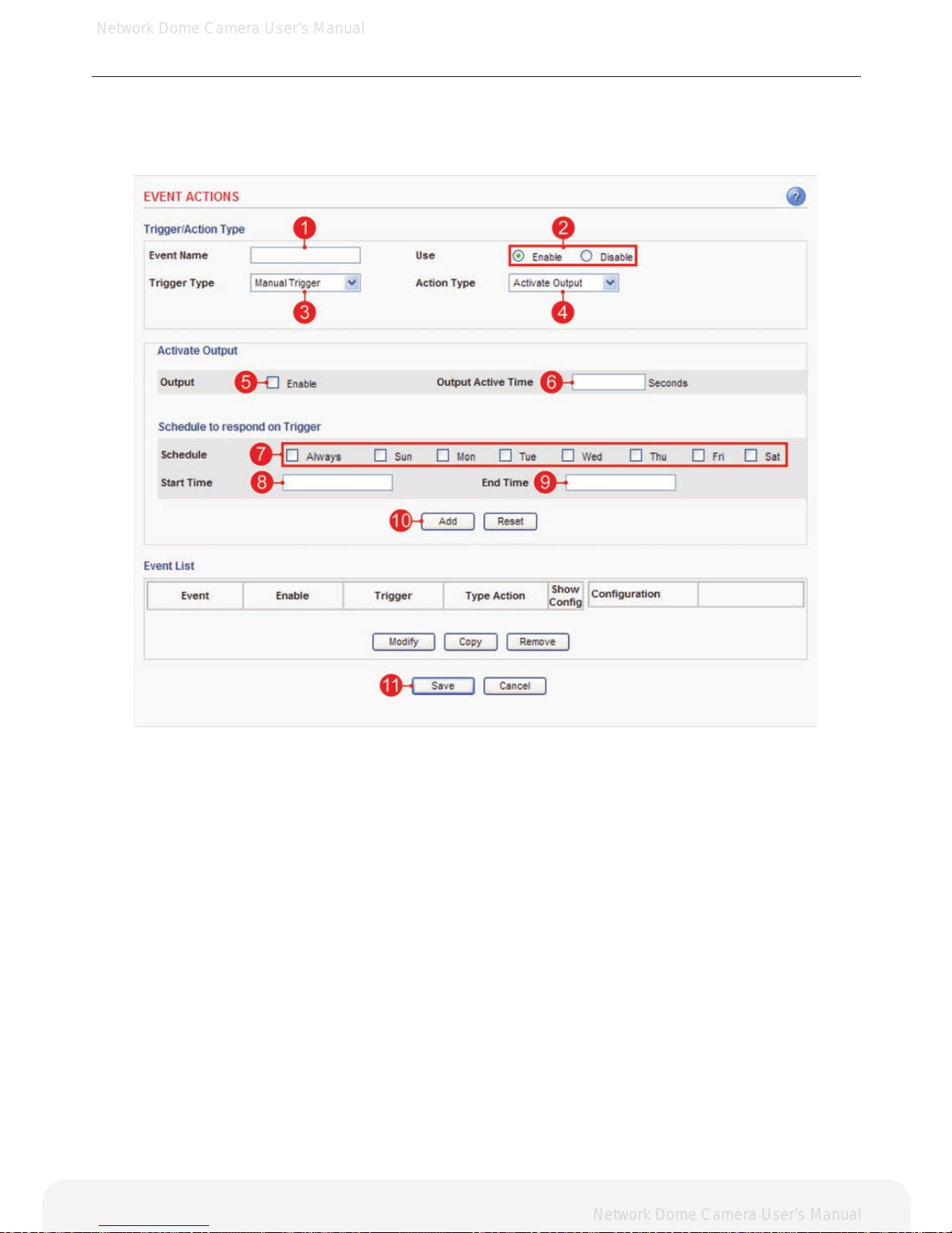
Action configuration for [Manual Trigger + Activate Output]
1. Enter a descriptive event name.
2. Select the enable.
3. Select the trigger type to manual trigger.
4. Select the action type to activate output.
5. Check the enable.
6. Enter the output active time.
7. Select the schedule by a day of the week.
8. Enter the start time in a 24hour format.
9. Enter the end time in a 24hour format.
10. Click the Add button to add configuration on the event list.
11. Click the Save button to save configuration.
Page 35
Network Dome Camera User’s Manual
Network Dome Camera User’s Manual
35
Conguring the Network Camera
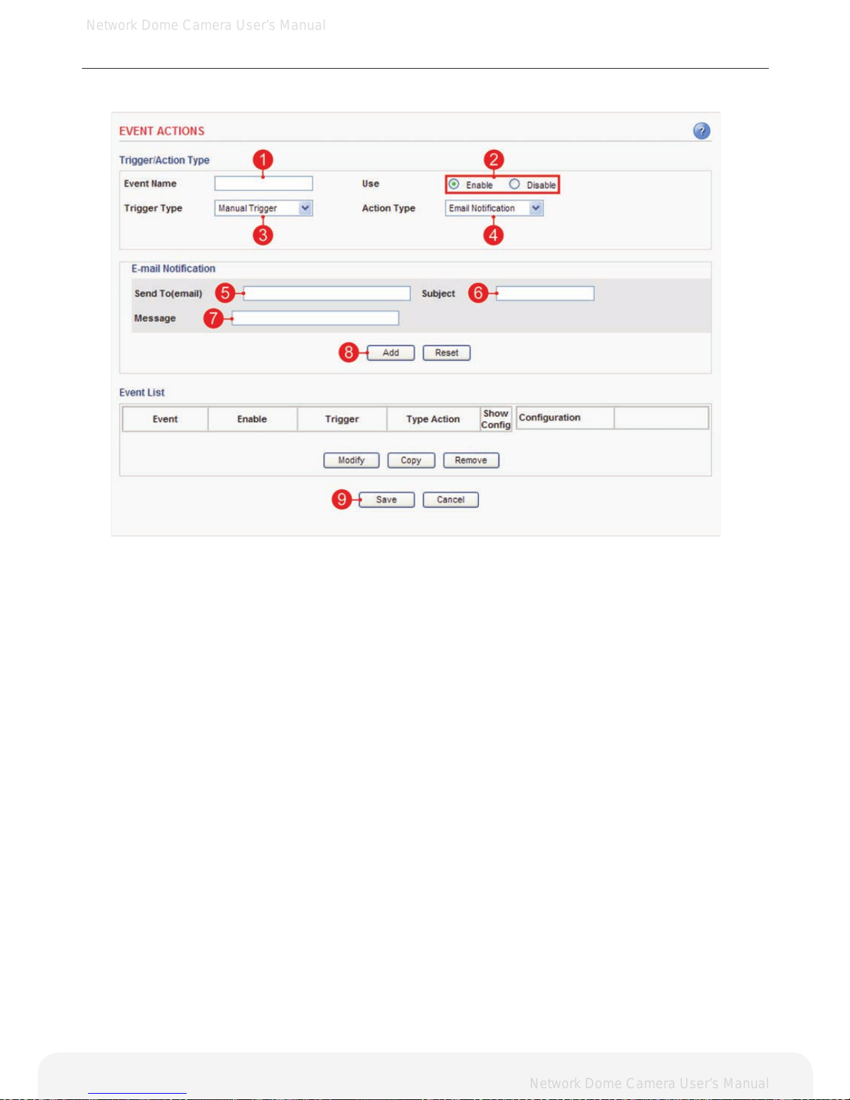
Action configuration for [Manual Trigger + E-mail Notification]
1. Enter a descriptive event name.
2. Select the enable.
3. Select the trigger type to manual trigger.
4. Select the action type to e-mail notification.
5. Enter the e-mail address which receives notification.
6. Enter a descriptive subject.
7. Enter a descriptive message.
8. Click the Add button to add configuration on the event list.
9. Click the Save button to save configuration.
Page 36
Network Dome Camera User’s Manual
Network Dome Camera User’s Manual
36
Conguring the Network Camera
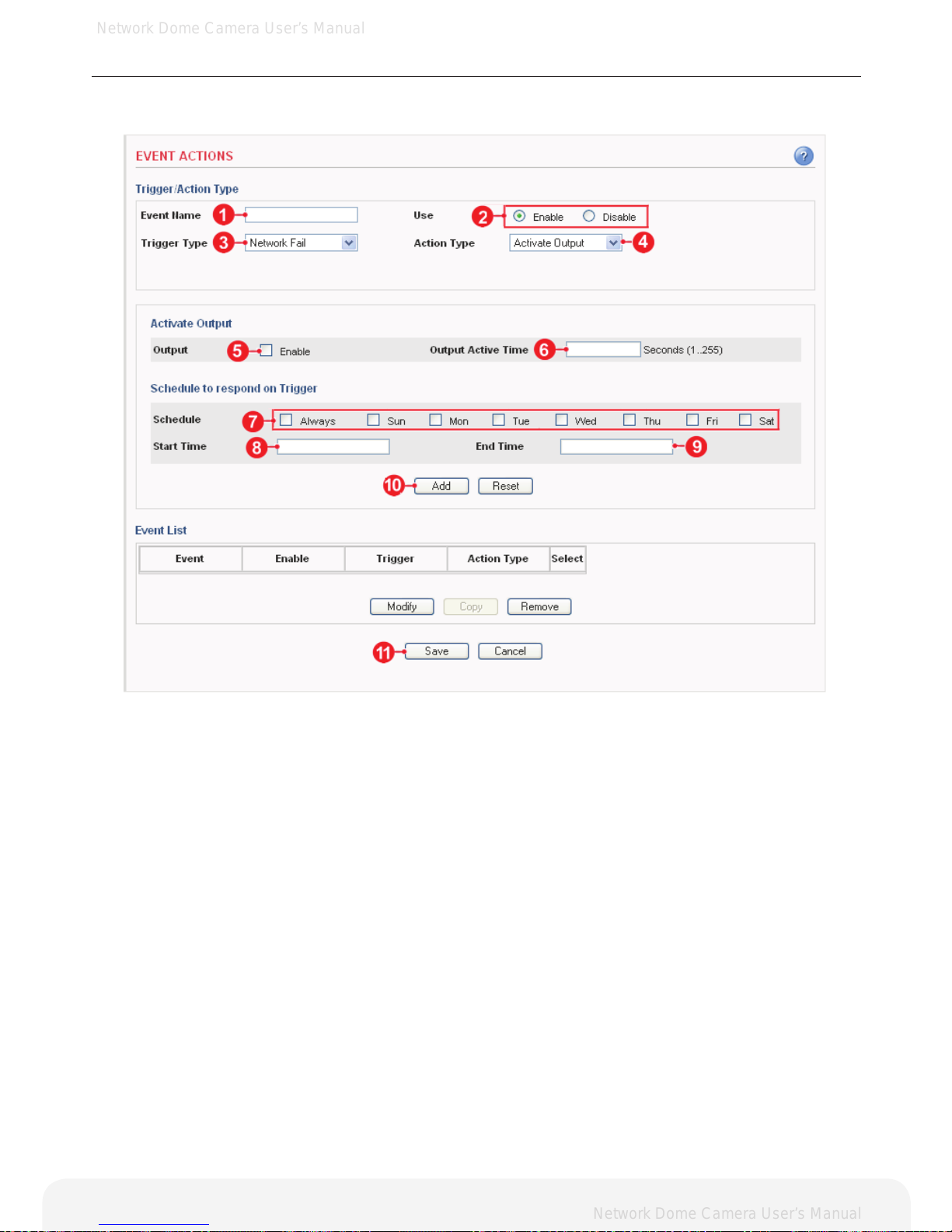
Action configuration for [Network Fail + Activate Output]
1. Enter a descriptive event name.
2. Select the enable.
3. Select the trigger type to network fail.
4. Select the action type to activate output.
5. Check the enable.
6. Enter the output active time.
7. Select the schedule by a day of the week.
8. Enter the start time in a 24hour format.
9. Enter the end time in a 24hour format.
10. Click the Add button to add configuration on the event list.
11. Click the Save button to save configuration.
Page 37
Network Dome Camera User’s Manual
Network Dome Camera User’s Manual
37
Conguring the Network Camera
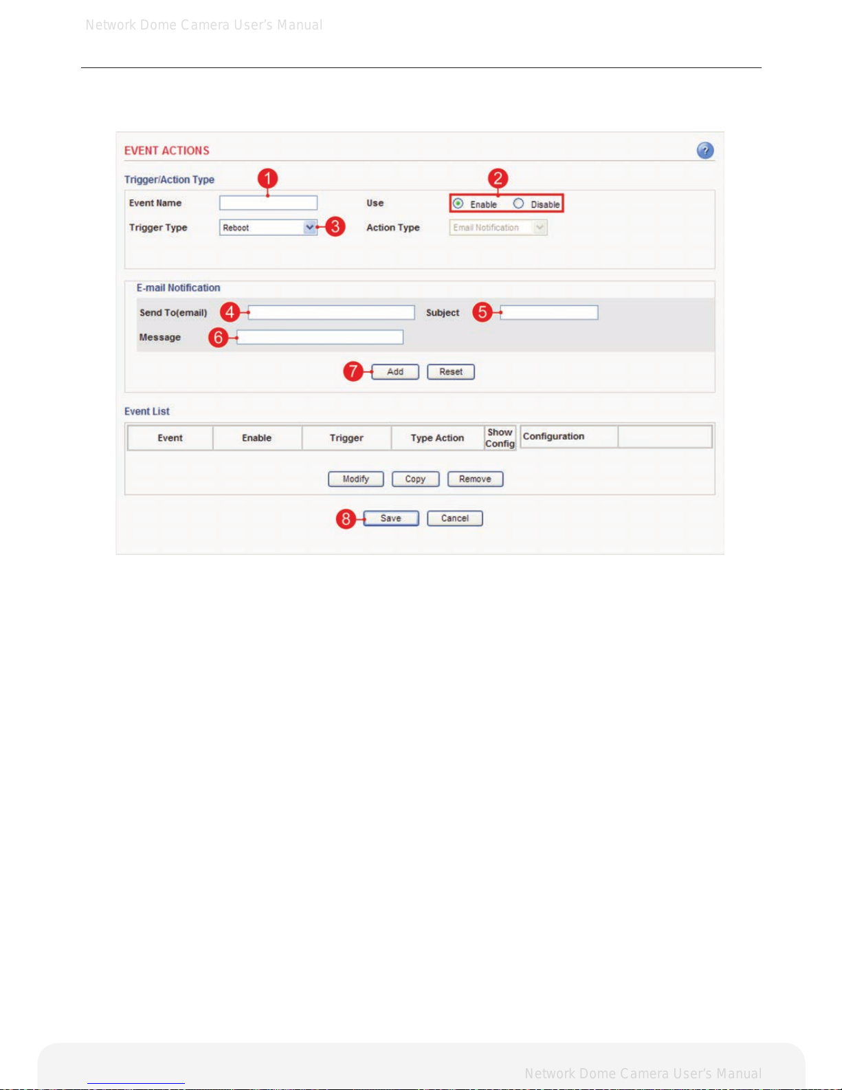
Action configuration for [Reboot]
1. Enter a descriptive event name.
2. Select the enable.
3. Select the trigger type to reboot.
Note: Action type is pre-selected to e-mail notication.
4. Enter the e-mail address which receives notification.
5. Enter a descriptive subject.
6. Enter a descriptive message.
7. Click the Add button to add configuration on the event list.
8. Click the Save button to save configuration.
Page 38
Network Dome Camera User’s Manual
Network Dome Camera User’s Manual
38
Conguring the Network Camera
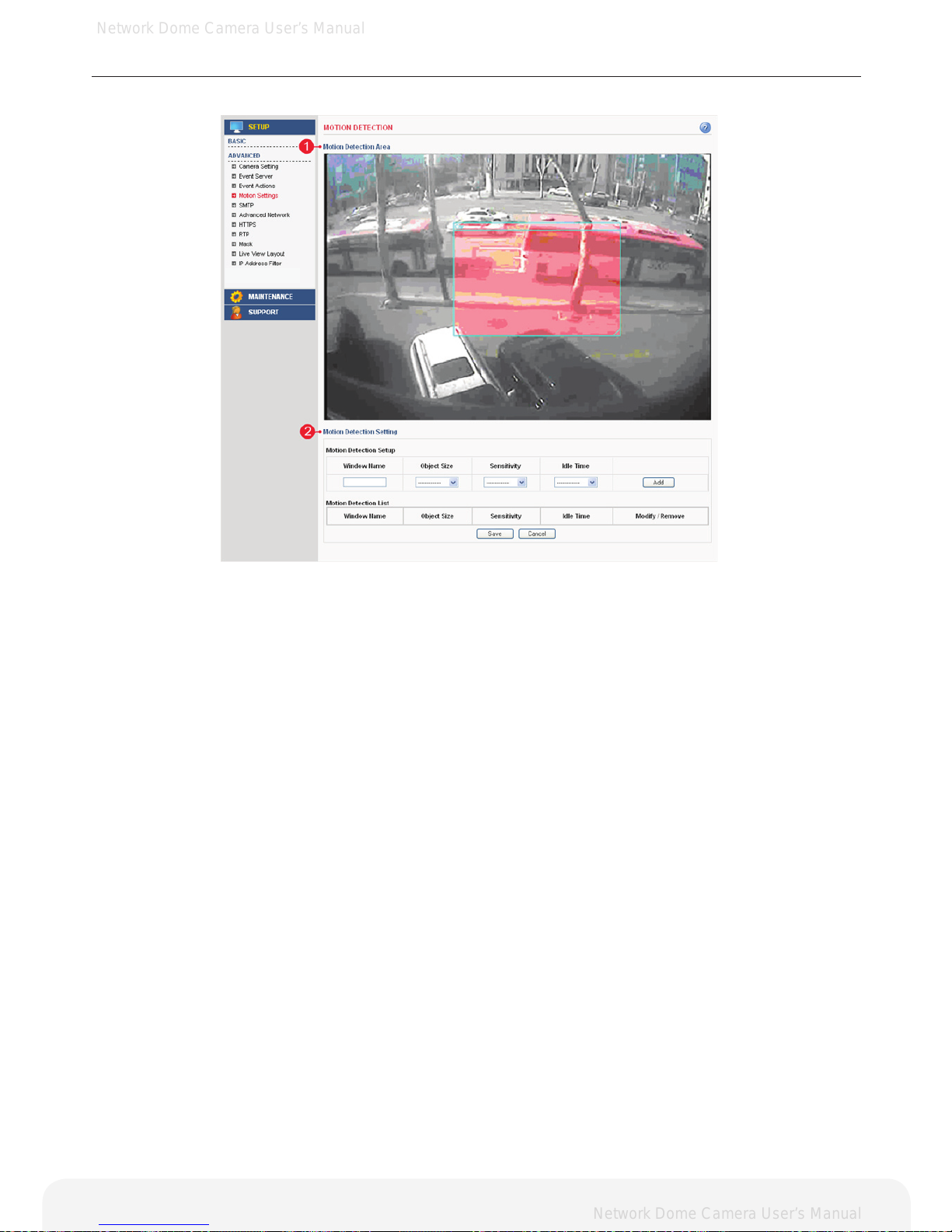
Advanced > Motion Settings
1. Motion Detection Area
A. This screen displays the live video image and users can configure the motion
detection field as desired on the screen.
2. Motion Detection Setting
A. Motion Detection Setup – Creates Motion Detection field. Enter the name of the Motion
Detection field, Object Size, Sensitivity and Idle Time. Click the add button to create the
new field.
B. Motion Detection List – Display all of the Motion Detection fields. Click the modify button to
modify setting values. Click the remove button to erase the Motion Detection field.
Note: A total of 5 motion elds can be congured.
Page 39
Network Dome Camera User’s Manual
Network Dome Camera User’s Manual
39
Conguring the Network Camera
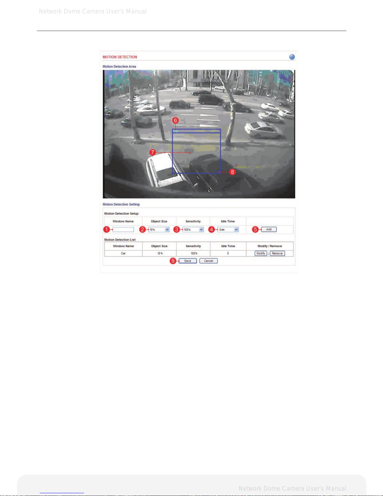
Configuration of motion detection
1. Enter a descriptive window name.
2. Select the Object Size.
Note: Higher level – Only very large objects trigger motion detection.
Lower level – Even small objects trigger motion detection.
(Recommended values: 10 ~ 20%)
3. Select Sensitivity.
Note: Higher level – Ordinary colored objects on ordinary backgrounds will trigger the motion detection.
Lower level – Only very bright objects on a dark background will trigger the motion detection.
(Recommended values: 40 ~ 50%)
4. Select Idle Time.
Note: Set the idle time to avoid continued event triggering by motion detection. Event will not be triggered
again during this period of time.
5. Click the add button to create a new Motion Detection window.
6. Display the name of Motion Detection window.
7. Click the center of the window and drag to the desired position.
8. Drag the bottom right-hand corner to adjust the window size.
9. Click the save button to save conguration.
Examples:
A. Avoid triggering on small objects in the video image by setting the Object Size level to high.
B. To reduce the number of triggers when there are a lot of movements during a short period of time, select
a high Idle Time level.
C. To only detect ashing light, low Sensitivity should be selected. In other cases, a high Sensitivity level is
recommended.
Page 40
Network Dome Camera User’s Manual
Network Dome Camera User’s Manual
40
Conguring the Network Camera
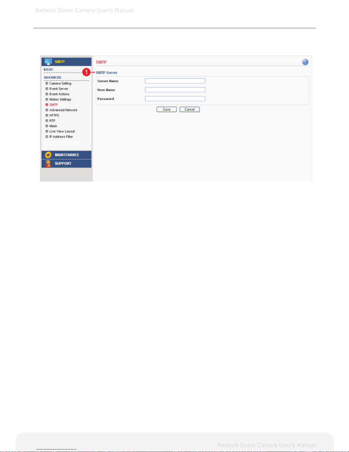
Advanced > SMTP
This section describes how to configure the SMTP server.
1. SMTP Server
A. Server Name – Enter the SMTP server’s Network address or host name.
Important: A DNS server must be specied in the Setup>Advanced>Advanced network if you are using a
host name.
B. User Name – Enter the user account which is registered with the SMTP server.
C. Password – Enter the user password.
Note: If your mail server does not require authentication, you don’t need to enter the user name and
password.
Page 41
Network Dome Camera User’s Manual
Network Dome Camera User’s Manual
41
Conguring the Network Camera
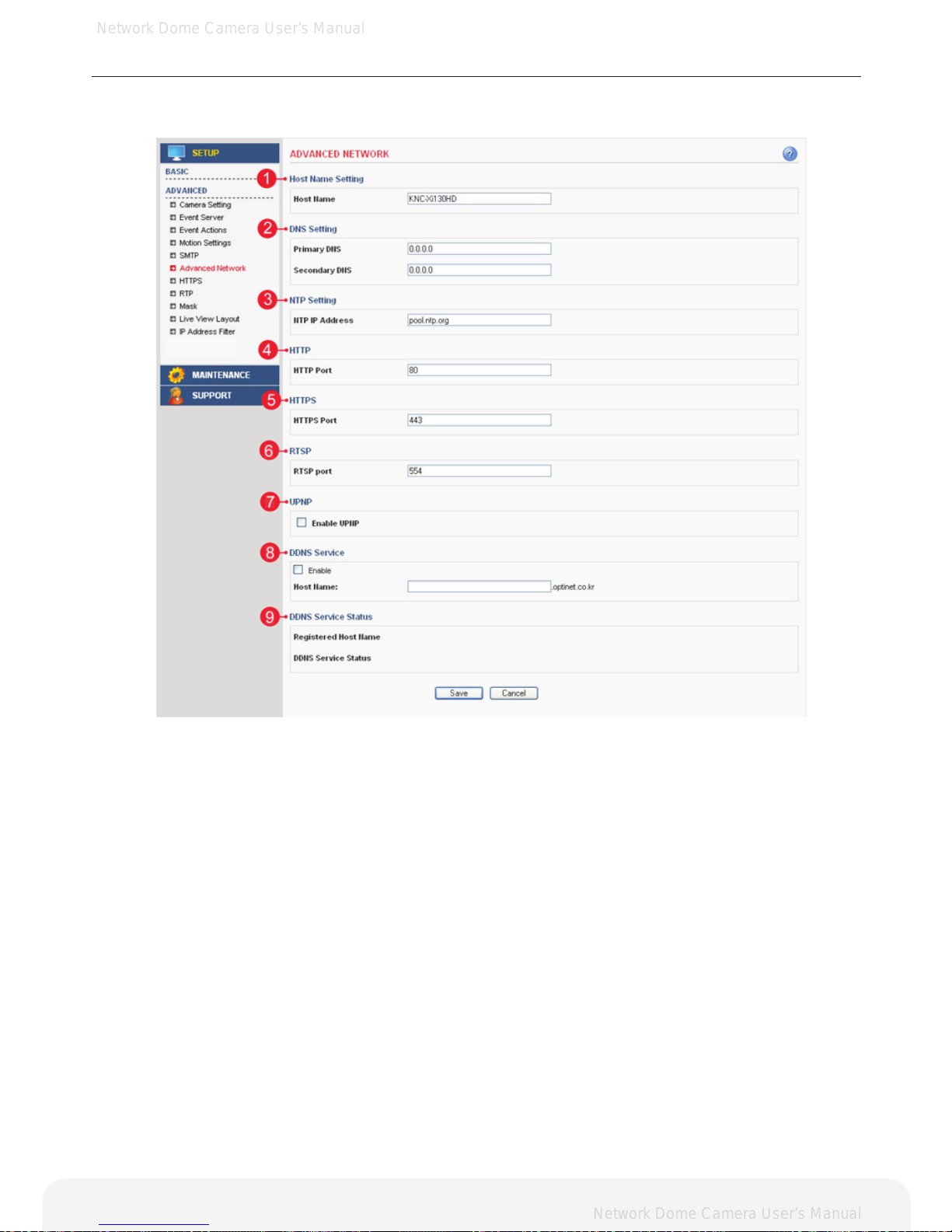
Advanced > Advanced Network
This section describes the advanced network settings.
1. Host Name Setting
A.Host Name – The Network Camera can be accessed using a host name instead of an IP address.
The host name is usually the same as the assigned DNS name. It is always the rst part of a fully qualied
domain name and is always one word, with no period.
2. DNS Setting
A. Primary DNS - Enter the IP address of the primary DNS server. This server provides the translation of
host names to the IP addresses on your network.
B. Secondary DNS - Specify the IP address of the secondary DNS server.
This will be used if the primary DNS server is unavailable.
Note: When setting up the Network Camera to use DHCP servers for obtaining network settings, the
Network Camera will automatically look up and use the DNS server settings as provided by DHCP.
Page 42

Network Dome Camera User’s Manual
Network Dome Camera User’s Manual
42
Conguring the Network Camera
3. NTP Setting
A. NTP IP Address – Enter the NTP server’s IP address or host name.
Important: The DNS server must be specied if you are using a host name.
4. HTTP
A. HTTP Port – Enter the HTTP port the Network Camera will use. The default port is 80. Alternatively, any
port in the range 1024-65535 may be used, but check rst with your system administrator before changing
the default setting.
5. HTTPS
A. HTTPS Port – Enter the HTTPS port the Network Camera will use. The default port is 443. Alternatively,
any port in the range 1024-65535 may be used, but check rst with your system administrator before
changing the default setting.
6. RTSP
A. RTSP Port – Enter the RTSP port number the Network Camera will use. The default port is 554.
7. DDNS Service
A. Enable – Check this box to enable DDNS service.
B. Host Name – Enter the host name which you want to use for DDNS service.
8. UPNP
A. Enable UPNP – Check this box to enable UPNP.
9. DDNS Service Status
A. Displays the DDNS service’s status in your ip product.
Page 43
Network Dome Camera User’s Manual
Network Dome Camera User’s Manual
43
Conguring the Network Camera
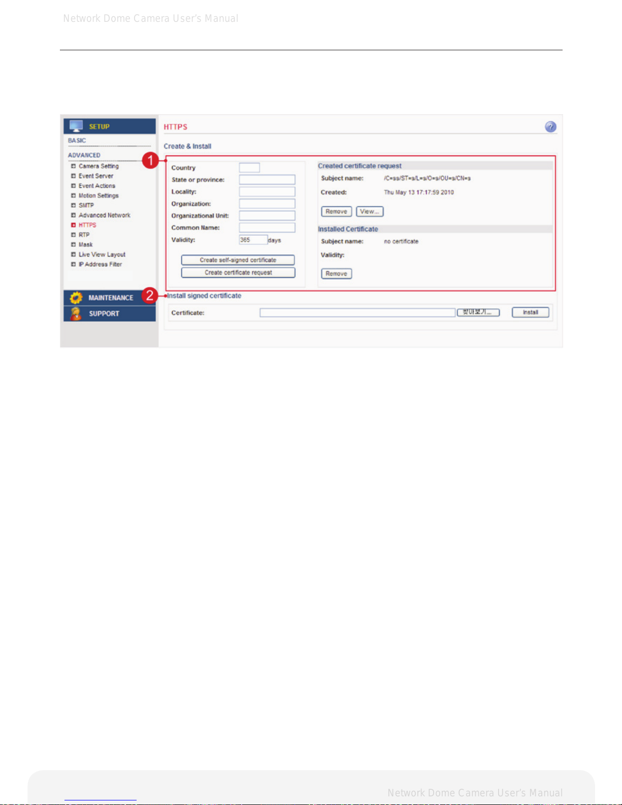
Advanced > HTTPS
This section describes the HTTPS settings. HTTPS provides encryption and secure identification
of the server over an insecure network.
1. Create
A. Country – Enter a 2 letter code name of the country where the certicate will be used.
B. State or province – Enter the name of the local administrative region where the certicate will be used.
C. Locality – Enter any other geographical information of the place where the certicate will be used.
D. Organization – Enter the name of the organization to which the entity identied in the
‘Common Name’ belongs to.
E. Organizational Unit – Enter the name of the organizational unit or a department to which the
entity identied in the ‘Common Name’ belongs to.
F. Common Name – Enter the name of a person or an entity that the certicate identies with.
G. Validity – Enter the number of days for which the certicate is valid, used in the case of
self-signed certicate only.
H. Create self-signed certicate – Clicking this button after lling all the above details creates a
self-singed certicate.
I. Create certicate request – Clicking this button after lling all the above details except for
Validity(validity is used only for a self signed certicate) creates a certicate request which is in the form
of PEM formatted data.
J. Created Certicate Request – Shows the details of the certicate request currently present in the server.
• Remove – Removes an already existing certicate.
• View – Shows the PEM formatted certicate request.
K. Installed Certicate – Shows the details of the self signed certicate.
• Remove – Removes an already existing certicate.
2. Install signed certicate
A.Certicate – The certicate is installed by browsing to the location of the certicate and then clicking Install.
Note: Only one certicate can be installed at a time. To install a new certicate any existing certicate
should be removed rst.
Page 44
Network Dome Camera User’s Manual
Network Dome Camera User’s Manual
44
Conguring the Network Camera
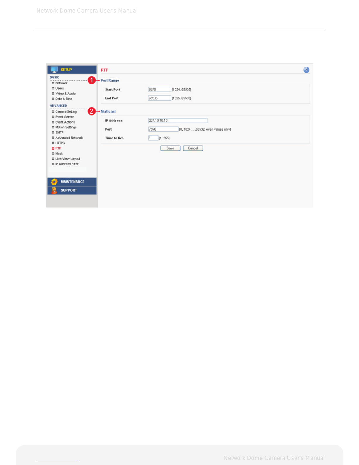
Advanced > RTP
This section describes the RTP settings. The RTP settings manage the IP addresses and port
numbers to use for video streams.
1. Port Range
A. The RTP port range denes the range of ports that the video streams will automatically use. Limit the
range of ports permitted for RTP unicast or multicast by entering the Start port and End port in the provided
elds with the value between 1024 and 65535.
2. Multicast
A. IP Address – Enter the IP address that the Network Camera will use for multicast. Multicast IP address
has to be specied in the range 224.xxx.xxx.xxx-239.xxx.xxx.xxx.
B. Port – Enter the multicast port the Network Camera will use for multicast. The multicast port can be
adjusted in the range 1024-65534 but it has to be even values. If the multicast port is 0, the Network
Camera will assign the multicast port automatically.
C. Time to Live – If IP packets (i.e. data) fail to get delivered to their destination within a reasonable length of
time (which could be for various reasons), this setting will tell network routers when to discard the packet.
The value is usually measured in ‘hops’, i.e. the number of network routers that can be passed before the
packet arrives at its destination or drops in the middle.
Page 45
Network Dome Camera User’s Manual
Network Dome Camera User’s Manual
45
Conguring the Network Camera
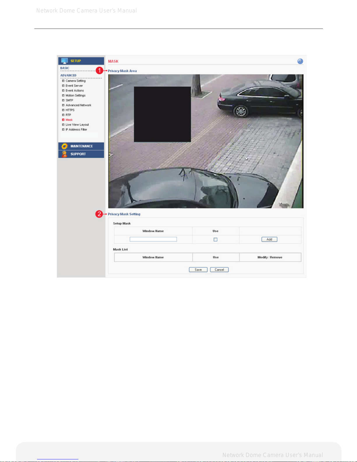
Advanced > Mask
This section describes how to configure privacy mask.
1. Privacy Mask Area
A. This screen displays the live video image and user can congure a Privacy Mask window as
desired on the screen.
2. Privacy Mask Setting
A. Setup Mask – Creates Privacy Mask window. Enter the name of the Privacy Mask window,
enable the check box for use then click the add button to create a new window.
B. Mask List – Display all of the Privacy Mask windows. Click the modify button to modify setting values.
Click the remove button to erase the Privacy Mask window.
Note: A total of 2 Privacy Mask window can be congured.
Page 46
Network Dome Camera User’s Manual
Network Dome Camera User’s Manual
46
Conguring the Network Camera
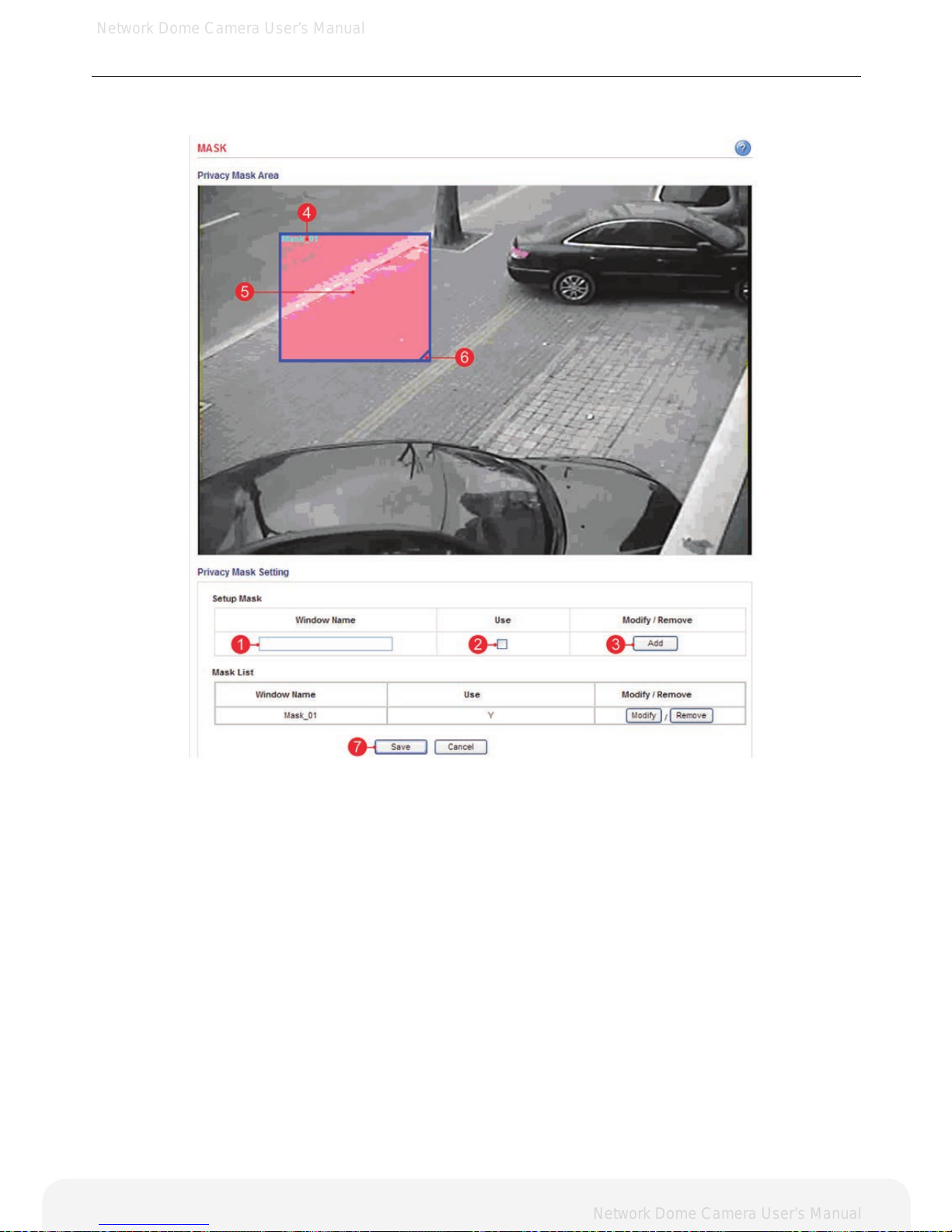
Configuration of privacy mask
Create a Privacy Mask window with the following steps as shown below.
1. Enter a descriptive window name.
2. Check the check box for use.
3. Click the add button to create the new Privacy Mask window.
4. Displays the name of Privacy Mask window.
5. Click the center of the window and drag to the desired position.
6. Drag the bottom right-hand corner to adjust the window size.
7. Click the save button to save the conguration.
Page 47
Network Dome Camera User’s Manual
Network Dome Camera User’s Manual
47
Conguring the Network Camera
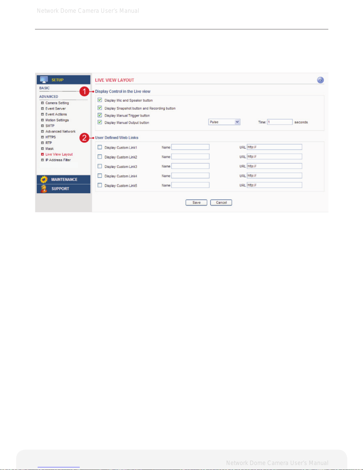
Advanced > Live View Layout
This section describes the settings of the live view layout.
1. Display Control in the Live View
- The live view page can be customized as desired. To enable the control buttons,
check the preferred check box.
- In case of Manual alarm button, users can select pulse or active/inactive mode.
2. User Dened Web Links
- Displays the web link specied by the user in the live view page.
Page 48
Network Dome Camera User’s Manual
Network Dome Camera User’s Manual
Conguring the Network Camera
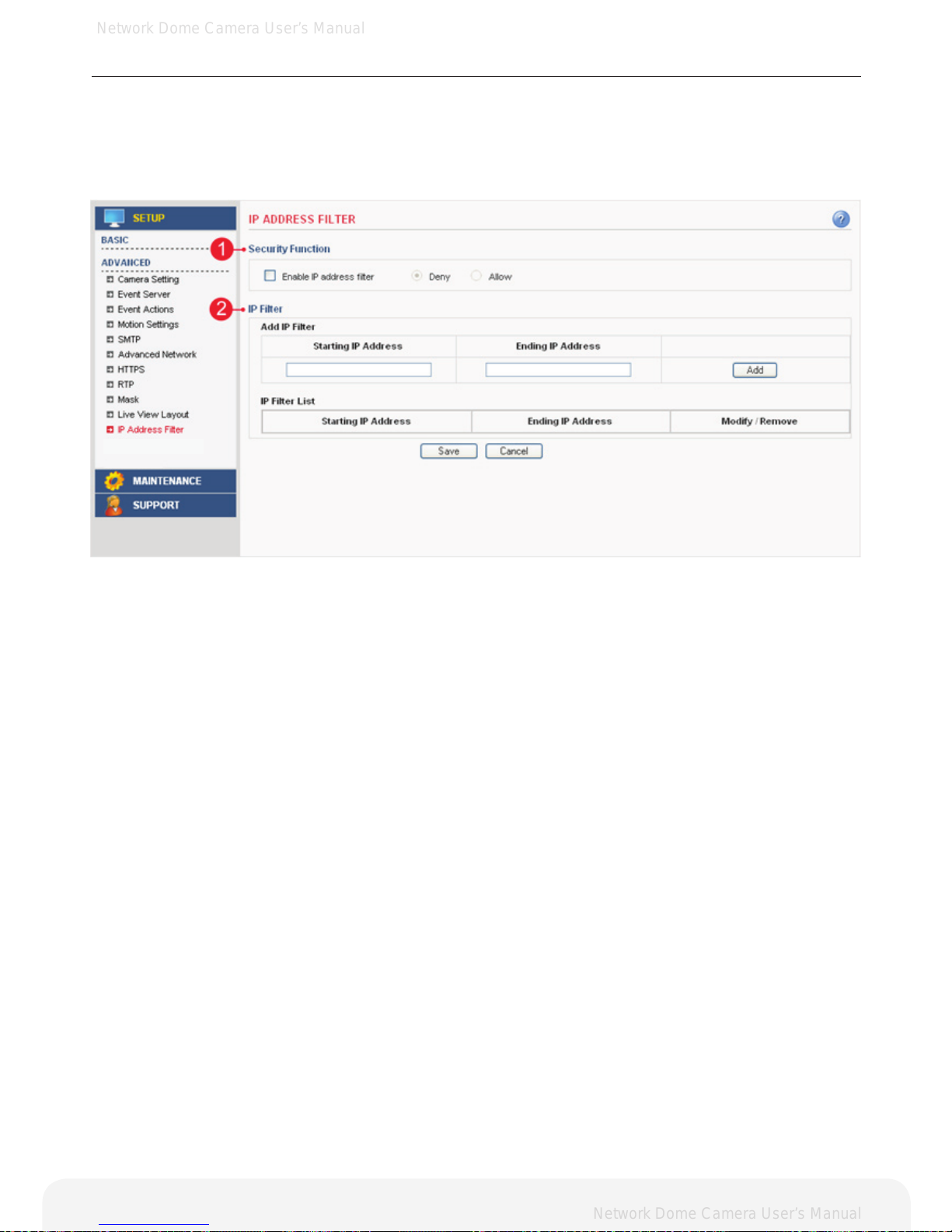
Advanced > IP Address Filter
This section describes how to deny access to the Network Camera from a specific IP address.
1. Security Function: Deny
A. Enable IP address lter – Checking this option will allow the user to either deny or allow access to the
ip address in the list, which can be controlled by clicking on Deny or Allow option.
2. IP Filter
A. Add IP Filter – Enter the IP address that you want to reject. The IP address can be entered by range.
B. IP Filter List – Displays all of the denied IP address. Click the modify button to modify setting values.
Click the remove button to erase the IP address.
48
Page 49
Network Dome Camera User’s Manual
Network Dome Camera User’s Manual
Conguring the Network Camera
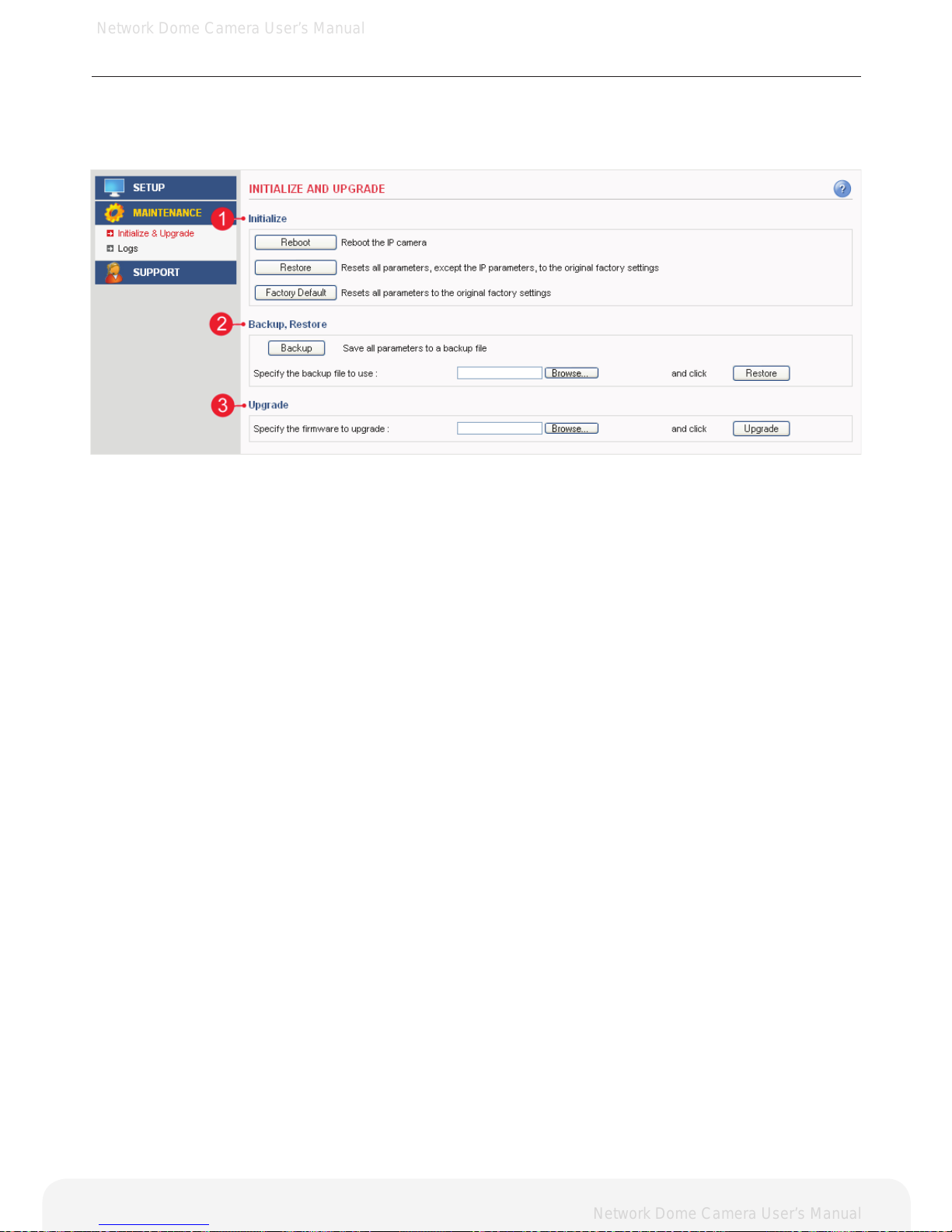
Maintenance > Initialize & Upgrade
This section describes how to reset the Network Camera and upgrade the firmware.
1. Initialize
A. Reboot – Reboot the Network Camera.
B. Restore – Reset all setting values, except network setting values.
C. Factory Default – Reset all setting values to the original factory settings.
Important: The Default button should be used with caution. Pressing this will return all settings to the factory
default values, which also means that the IP address will need to be set again to make the unit accessible.
2. Backup, Restore
A. Backup – Click the backup button to make a backup of all of the setting values in the Network Camera.
B. Restore – If it is necessary to restore the camera to previous backed up settings, click the browse button
to locate the saved backup le and then click the restore button.
3. Upgrade
Upgrade – To upgrade the rmware for the Network Camera, click the browse button to nd the rmware le
and then click the upgrade button.
49
Page 50
Network Dome Camera User’s Manual
Network Dome Camera User’s Manual
Conguring the Network Camera
Maintenance > Logs
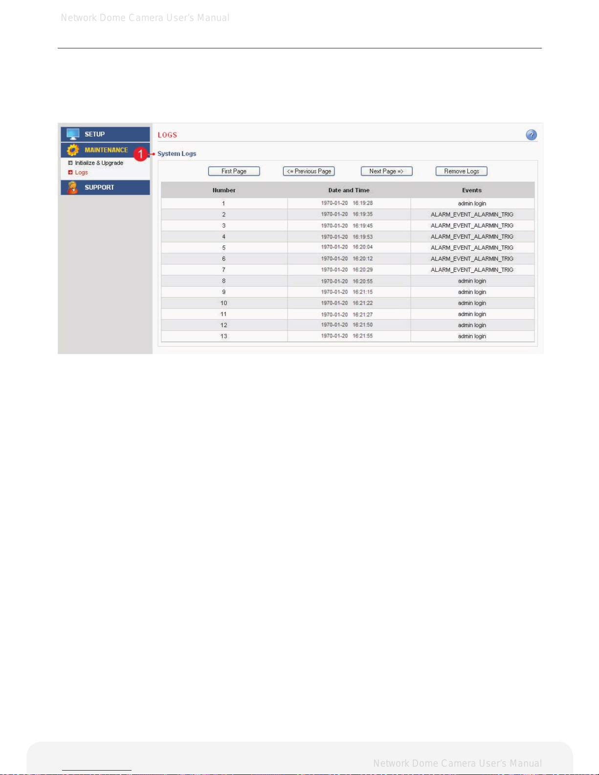
This section describes the system logs.
1. System Logs
The Network Camera records when a particular event occurs in the log record.
A. First Page – Go to the rst page of the log record.
B. Previous Page – Go to the previous page of the log record.
C. Next Page – Go to the next page of the log record.
D. Remove Logs – Remove all of the log record.
50
Page 51
Network Dome Camera User’s Manual
Network Dome Camera User’s Manual
Conguring the Network Camera
Support > System / Help
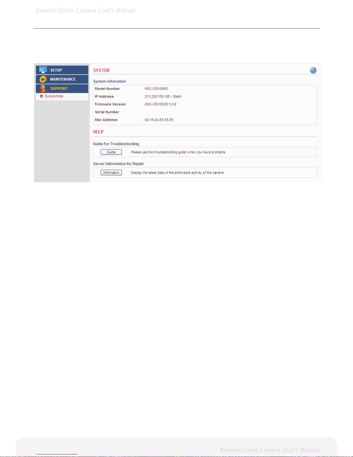
This section describes the system information and help menu.
1. System Information
Displays the system information of the Network Camera.
2. Guide for Troubleshooting
If you suspect a problem is being caused by incorrect conguration or some other minor problem,
consult the troubleshooting guide.
3. Server Information for Repair
It would be helpful when you contacting your support channel with this report.
51
Page 52
Network Dome Camera User’s Manual
Network Dome Camera User’s Manual
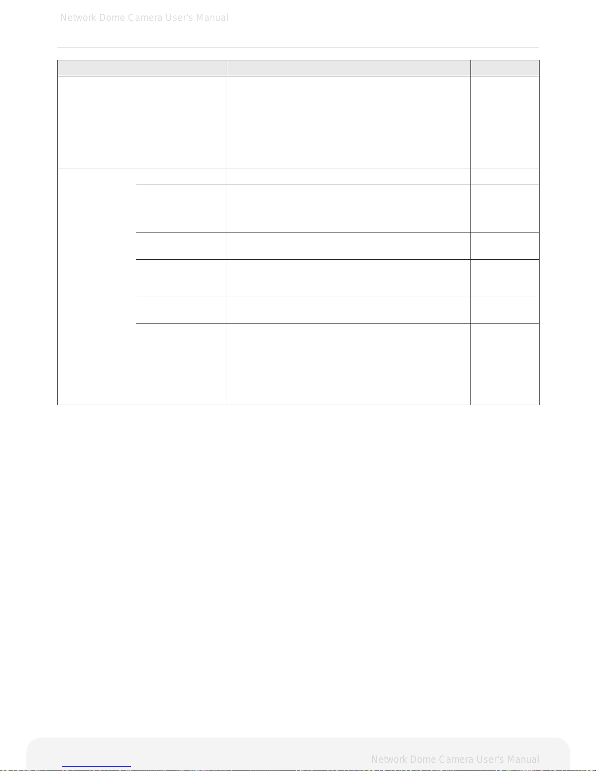
Product Specications
ITEM DESCRIPTION NOTE
Image Device 1/3” SONY 2.1M Progressive Scan CMOS
Lens Pinhole Lens , Board Lens Unit: mm
Day and Night True Day & Night with ICR Mechanism
Minimum Illumination Color: 0.625 lux, B/W: 0.31 lux
Video
Video Codec
H.264 Main Prole
Motion JPEG
Resolutions
(H.264/MJPEG)
H.264 : MAX 1920x1080 + Analog Output @ 30fps
MJPEG : MAX 1280x720 @30fps
Video Streaming
Simultaneous Motion JPEG and H.264
Controllable frame rate and bandwidth
Constant and variable bit rate (H.264)
Image Settings
Brightness, Contrast, Saturation, Sharpness, White
Balance, Exposure Control, Back Light Compensation
Compression levels : 100 (Motion JPEG)
Viewer Magnication : 0.5x, 1x, 1.5x, 2x
Overlay capabilities : time, date, text, privacy mask
Network
Security
Multiple user access levels with password protection
IP address ltering: Deny, Allow
Supported
Protocols
IPv4, HTTP, HTTPS, TCP, RTSP, RTP, UDP, IGMP,
RTCP, SMTP, FTP, ICMP, DHCP, ARP, DNS, DDNS,
UPnP
System
Integration
API
Onvif 1.0
Open API for software integration, including API, SDK
Intelligent Video Video motion detection
Alarm Triggers
Intelligent video, external inputs, manual triggers,
Network Fail, Reboot, Schedule
Alarm Events File upload via FTP, e-mail, Notication via e-mail
52
Page 53
Network Dome Camera User’s Manual
Network Dome Camera User’s Manual
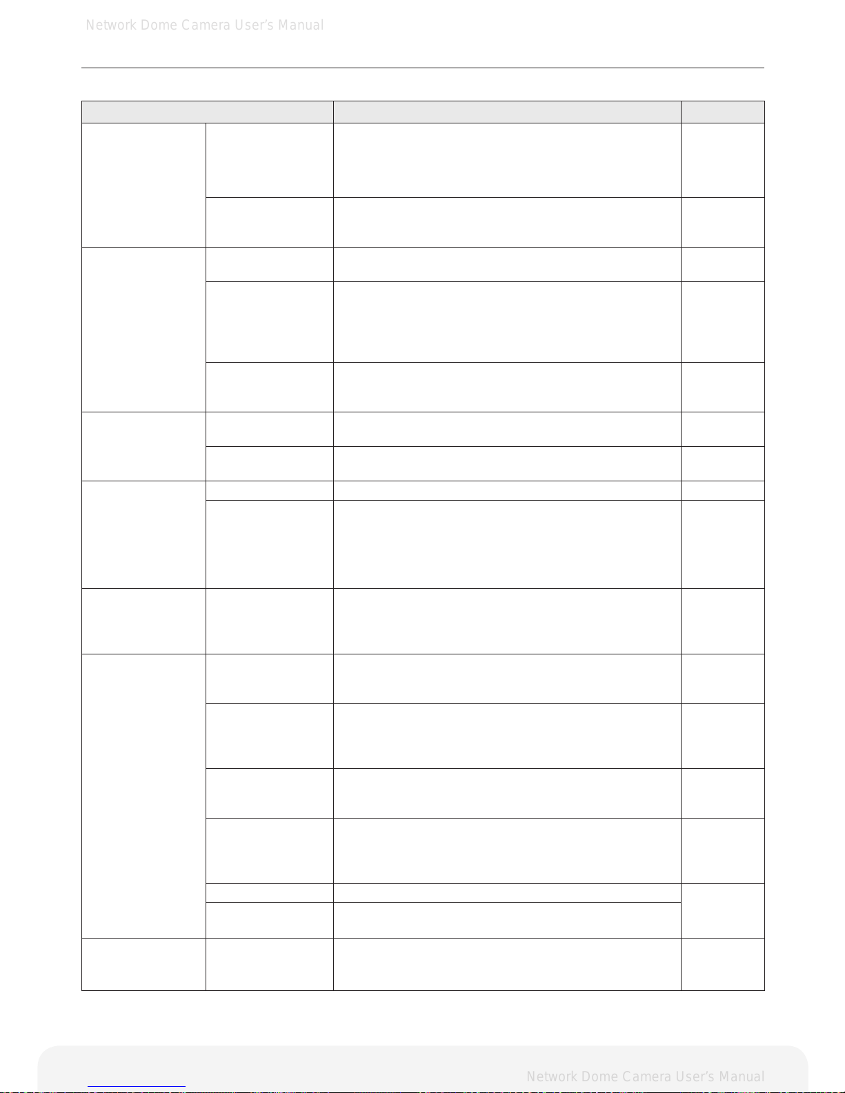
Product Specications
ITEM DESCRIPTION NOTE
Web Viewer
Video format change
Stream play / stop
Snapshot
Instant recording(Max 5. minutes)
Manual trigger
Output control
Screen magnication
Status indicator (video, record, alarm, motion)
General
Enclosure Plastic case
Processors and
Memory
CPU : ARM 926EJ-S
RAM : 128 MB
Flash : 64 MB
Real-time clock with backup battery
Power
DC12V 210mA
Power over Ethernet Class 3 (IEEE 802.3af)
Interfaces
RJ-45 for Ethernet 10baseT/100baseTX with PoE
3.5mm Power Input: DC 12V
connector for Service Video
Operating
Conditions
Temperature: - 10°C ~ +50°C (14°F ~ 122°)
Humidity 20-80% RH (non-condensing)
Accessories
Installation Guide, CD with installation and management tools, CMS software, installation guide and
User’s guide
53
Page 54
Network Dome Camera User’s Manual
Network Dome Camera User’s Manual
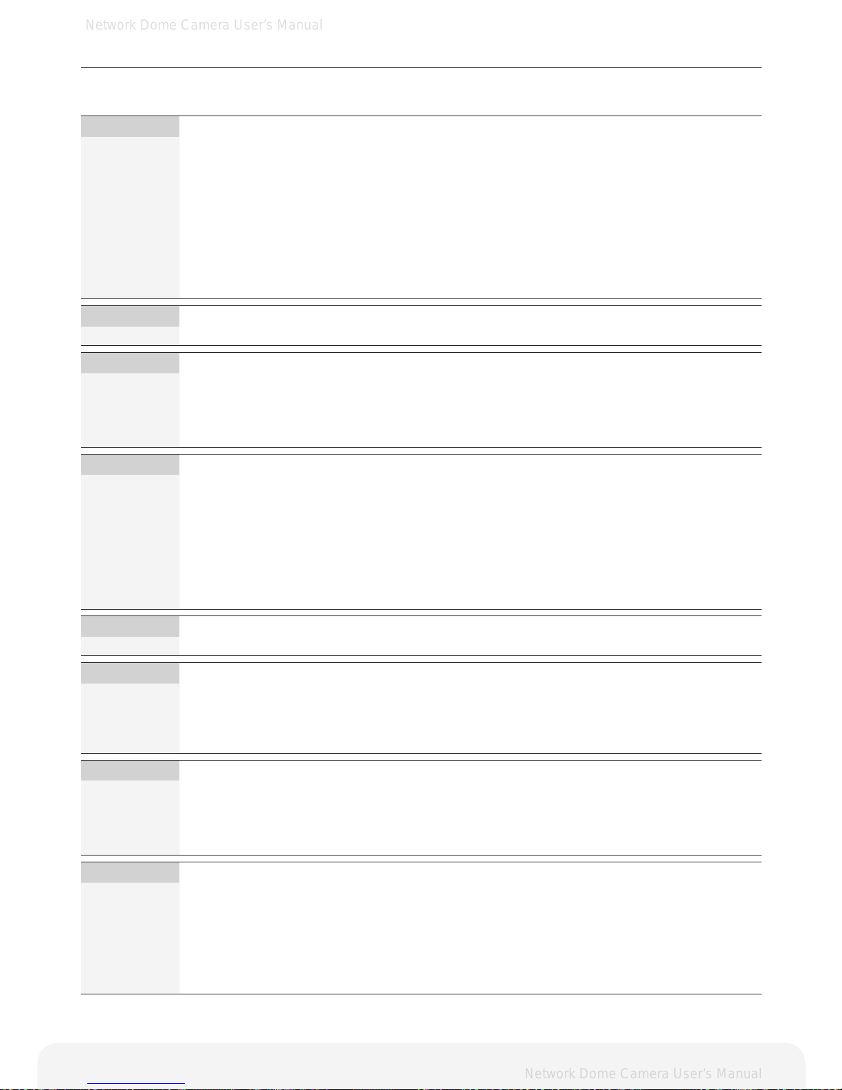
Troubleshooting
This section describes the symptoms, possible causes and corrective actions.
Symptoms Remedial Actions Reference
Problems with IP
address setting
The Network
Camera is located
on a different
subnet.
If the Network Camera and your computer are located
on different subnets, you will not be able to set the
IP address. Contact your network administrator for
obtaining an IP address on the same subnet as the
computer that you are performing installation from.
The IP address
is being used by
another device.
Contact your network administrator. You must obtain a
new IP address and reinstall the Network Camera.
The Network
Camera cannot
be accessed from
a web browser.
Cannot log in
Check if the user ID and password is correct. The ID
and password are case sensitive.
IP address has
been changed by
DHCP
Recongure the IP address using the IP Installer.
If a dynamic IP address via DHCP is required,
enable the DHCP and congure the SMTP Noti-
cation (Email) For IP Address Change from the
Setup>Basic>Network settings.
Installation
Guide
Other networking
problems
Check the network cable by connecting it to another
network device, then Ping the device from your computer.
The Network
Camera cannot
be accessed
externally
Firewall protection
Check the Internet rewall with your network administrator.
Default gateway
required
Check if you need to congure the default gateway
settings.
13p
The Network
Camera does not
turn on
DC power supply Check the power.
PoE power supply
Check the Ethernet (CAT 5) cable that is connected
to a PoE compatible power supply unit. Some power
supply unit may not provide power when the total
power supply limitation is exceeded. Check the Operating Instructions of the PoE power supply unit for
maximum power output.
No image dis-
played in the web
viewer
ActiveX
To run the View Program in Microsoft Internet Explor-
er, congure your Web browser to allow the ActiveX
controls. Also, make sure that Web Viewer component
is installed on your PC.
9p
Video image
problems
Missing images in
uploads
This can occur when trying to use a larger image buffer than is actually available. Try lowering the frame
rate or the upload period.
Slow performance
Slow performance may be caused by e.g. heavy
network trafc, multiple users accessing the Network
Camera, low performance computer, using features
such as Motion Detection, Event action.
Image is not clear
Adjust the focus of the camera.
Check the target bit late (H.264) or image quality
(JPEG) is not congured too low.
16p ~ 18p
Video is stopped
Check if the network cable of the Network Camera is
correctly connected. In case user uses switches or
routers, check whether these network equipments are
working properly.
Installation
guide
Blank Screen Check the power source of the connected camera.
Video is often
broken
Lower the target bit late (H.264) or image quality
(JPEG)
Motion Detection
Function is not
working
Check if the Motion Detection is enabled.
Check the sensitivity level
Check the setting of the Motion Detection area.
44p ~ 46p
54
Page 55
Network Dome Camera User’s Manual
Network Dome Camera User’s Manual
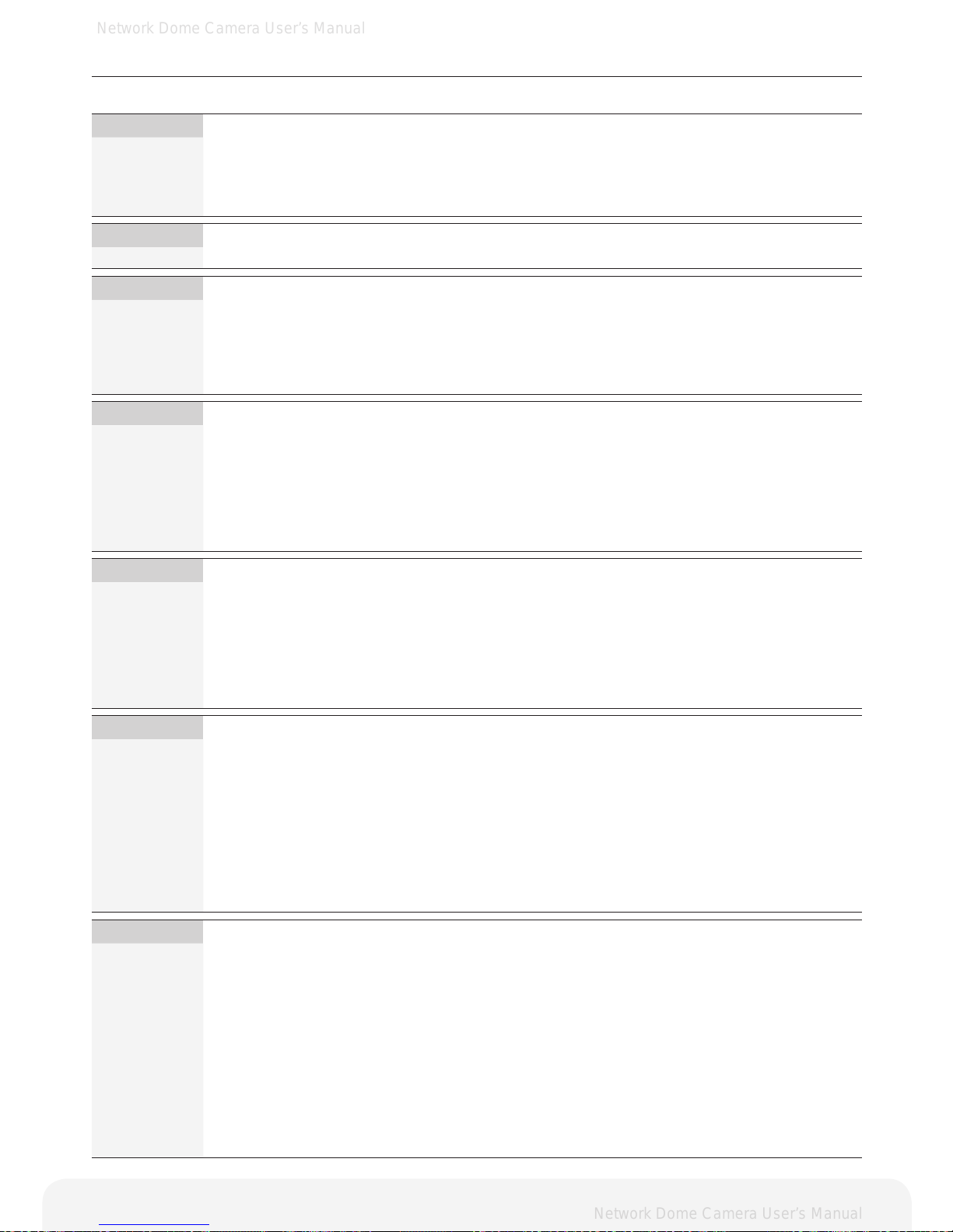
Glossary
This section provides glossary for understanding the Network Camera.
A.
ActiveX: A control (or set of rules) used by a browser. ActiveX controls are often downloaded and
installed automatically as required.
API: Application Programming Interface. The API can be used for integrating products into other
applications.
ARP: Address Resolution Protocol. Used to associate an IP address to a hardware MAC address.
A request is broadcasted on the local network to nd out what the MAC address is for the IP
address.
Aspect ratio: A ratio of width to height in images. A common aspect ratio used for television screens and
computer monitors is 4:3. High-denition television (HDTV) uses an aspect ratio of 16:9.
B.
BOOTP : A protocol that can automatically congure a network device (give it an IP address).
C.
CGI: Common Gateway Interface. A set of rules (or a program) that allows a Web Server to com-
municate with other programs.
Client/Server: Describes the network relationship between two computer programs, in which one, the client
makes a service request from another - the server.
D.
DC-iri: The iris, a mechanism that automatically regulates the amount of light allowed entering to
CCD, is electrically controlled by the camera
dB (Decibels): A unit to measure sound level changes. A 3dB change is the smallest level change we can
hear. A gain of 0dB will leave the signal level unchanged.
De-interlacing: De-interlacing is the process of converting a stream of interlaced frames to a stream of pro-
gressive frames.
A-DSL : Digital Subscriber Line. A means of transferring data via standard phone line.
E.
Ethernet: A widely used networking standard.
F.
Firewall: A virtual barrier between a LAN (Local Area Network) and other networks, e.g. the internet.
FTP: File Transfer Protocol. Used for the simple transfer of les to and from an FTP server.
Full-duplex: Transmission of data in two directions simultaneously.
G.
G.711: G.711 is the international standard for encoding telephone audio on 64 Kbps channel. It is a
pulse code modulation (PCM) scheme operating at 8 kHz sample rate.
G.726: Frequently used speech-compression algorithm in telecommunications due to its high per-
ceived speech quality and low resource requirements.
H.
Half-duplex: A half-duplex link communicates in one direction at a time only, Just like a walkie-talkie. Two
way communications is possible, but not simultaneously.
HTTP: Hypertext Transfer Protocol. The set of rules for exchanging les (text, images, sound, video,
and other les) on the World Wide Web.
HTTP-S:
(HTTPS)
An extension to the HTTP protocol to support the transmitting data securely over the World
Wide Web.
55
Page 56
Network Dome Camera User’s Manual
Network Dome Camera User’s Manual
Glossary
I.
Intranet : A private network limited to an organization or corporation. Usually closed to external trafc.
IP: Internet Protocol.
IP address: A unique set of numbers used by a computer on the network to allow it to be identied and found.
J.
JPEG: A standard image format, used widely for photographs. Also known as JPG
L.
LAN: A local area network (LAN) is a group of computers and associated devices that typically
share common resources within a limited geographical area.
Linux: A popular operating system that is “open source” and practically free of charge.
Lux: A standard unit for light measurement.
M.
Mbit/s: Megabits per second. A unit for measuring speeds in networks.
A LAN might run at 10 or 100 Mbit/s
MPEG4: A video compression standard that makes good use of bandwidth.
It can provide DVD-quality video streams at less than 1 Mbit/s.
Multicast: A bandwidth-conserving technology that reduces bandwidth usage by simultaneously
delivering a single stream of information to multiple network recipients.
P.
Ping: A small utility used for sending data packets to network resources to check that they are
working and that the network is intact.
Pre / post
alarm image:
The images from immediately before and after an alarm.
Protocol: A special set of rules governing how two entities will communicate. Protocols are found at
many levels of communication, and there are hardware protocols and software protocols.
R.
Router: A device that determines the next network point to which a packet should be forwarded on its
way to its nal destination. A router is often included as part of a network switch.
RTP: Real Time Transfer Protocol. A transfer protocol designed for the delivery of live content, e.g.
MPEG4.
RTSP: Real Time Streaming Protocol is a network control(e.g. play, stop, etc) protocol used in mul-
timedia, and a starting point for negotiating transports such as RTP, multicast and Unicast.
RTSP can be considered a “remote control” for controlling the media stream delivered by
a media server. RTSP servers typically use RTP as the protocol for the actual transport of
audio/video data.
S.
SMTP: Simple Mail Transfer Protocol is the protocol used to send e-mail across the Internet. SMTP
authentication is a way of allowing people outside of a domain to use an SMTP server when
sending e-mail.
SNMP: Simple Network Management Protocol. An application layer protocol that facilitates the
exchange of management information between network devices. It is part of the TCP/IP
(Transmission Control Protocol/Internet Protocol) protocol suite.
Subnet Mask: An IP address consists of two components: the network address and the host address. “Sub-
netting” enables a network administrator to further divide the host part of the address into two
or more subnets. The subnet mask identies the subnet to which an IP address belongs.
Switch: Whilst a simple hub transmits all data to all devices connected to it, a switch only transmits
the data to the device it is specically intended for.
56
Page 57
Network Dome Camera User’s Manual
Network Dome Camera User’s Manual
Glossary
T.
TCP / IP: Transmission Control Protocol/Internet Protocol. A suite of network protocols that determine
how data is transmitted. TCP/IP is used on many networks, including the Internet. TCP keeps
track of the individual packets of information and IP contains the rules for how the packets
are actually sent and received.
U.
UDP: The User Datagram Protocol is a communication protocol that offers a limited amount of ser-
vice when messages are exchanged between computers in a network that uses the IP. UDP
is an alternative to the TCP and, together with IP, is also known as UDP/IP.
Unicast: Communication between a single sender and a single receiver over a network.
A new connection is established for each new user.
URL: Uniform Resource Locator. An “address” on the network.
V.
Varifocal: A varifocal lens provides a various range of focal length, as opposed to a lens with a xed
focal length, which only provides one.
W.
WAN: Wide Area Network. Similar to a LAN, but on a larger geographical scale.
Web server: A program on a computer that delivers the resources requested by the web use
57
 Loading...