

Page 1
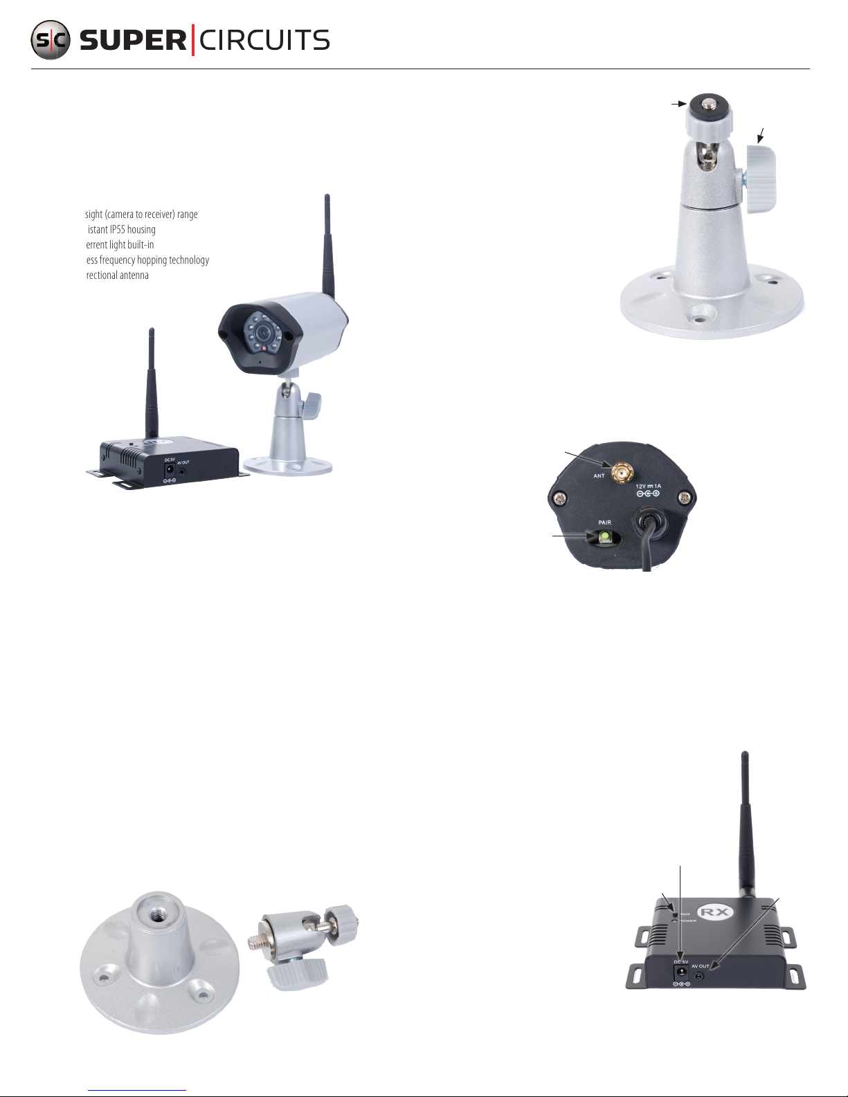
MVL24KIT Digital Camera/Receiver System
Setup and Usage Guide
The MVL24KIT 420 Line 2.4GHz Digi tal Wireless video IR camera ki t is a reliable and exceptionally easy to
install monitor ing solution for home or oce. It includes these features:
• 30’ IR Range
• 500’ line of sight (camera to receiver) range
• Weather-resistant IP55 housing
• Red LED deterrent light built-in
• Digital wireless f requency hopping techno logy
• 3 dB omnidirectional antenna
1. Tighten the adjustment knob on the side
of the gimbal assemb ly, then screw the
Rubber
washer
gimbal assembly onto the mounting
bracket until it is tight.
2. Anchor the camer a mounting bracket and
gimbal assembly onto a at surface at the
surveillance location. The hardware kit
provided is use ful for securing the bracket
onto most sur faces.
3. Attach the rubber washer (included in the
hardware kit) onto the gimbal bolt.
4. Loosen the adjus tment knob.
5. Screw the gimbal b olt into the threaded hole on the under side of the camera.
6. Aim the camera at your surveillance target, then tighten the adjus tment knob.
7. Attach the antenna to the back of the camer a assembly.
Antenna
connector
Adjustment
knob
A local area can accommodate up to 4 camera - receiver s ystems concurrently.
The MVL24KIT is compos ed of three SKUs: MVL24CM Digital Wireless IR Camera, MVL24RX 2.4GHz Digital
Wireless Receiver, and CON-4 female RCA to male BNC Adapter. An optional hi-gain antenna is available
for the MVL24RX re ceiver to improve reception and extend t he range of the system.
What’s in the box:
MVL24CM Digital Wireless IR Camera:
• Camera assembly
• 12 VDC power adapter
• Antenna (1)
• Mounting bracket and gimbal assembly
• Hardware kit
MVL24RX 2.4GHz Digital Wireless Receiver :
• Receiver (RX) module
• 5 VDC power adapter
• Antenna (1)
• A/V cable
• Hardware kit
Step 1. Installation - camera
The camera is ins talled onto a mounting bracket and gimbal assembly, then powered on.
Mounting Bracket
Gimbal Assembly
PAIR button
(under cap)
Power cord
8. Plug the camera power cord into the 12 VDC power adapter provided, then plug the power adapter
into a standard 120 VAC outlet. WARNING: Do not use the 5 VDC power adapter provided for the
RX module wit h the MVL24CM camera.
Step 2. Installation - RX module
1. Find a location f or the RX module that is within 50 0’ of the camera. If obstructions (walls, etc.)
exist between the camera and RX module, the module must be positioned closer to the camera.
The RX module c an be anchored to the mounting sur face, if necessary. The hardware k it provided is
useful for securing the module onto most sur faces.
2. Attach the A/V cable provided to the RX
module A/V OUT connector, then plug the
yellow RCA jack into a video recorder or
monitoring sy stem. (NOTE: This kit does not
support audio monitoring.)
DC5V
PAIR
button
power
connector
A/V OUT
connector
3. Attach the R X module antenna to the antenna
connector on t he back of the module.
4. Plug the RX module 5 VDC power adapter
into the DC5V connector on the R X module,
then into a standard 120 VAC outlet.
WARNING: Do not use the 12 VDC power
adapter provided for the MVL24CM camera
with the RX module.
www.supercircuits.com
1
MVL24KIT_SQ
Page 2
Step 3. PAIRing the camera and RX module
Specic ations - system
To PAIR the camera and RX module is the p rocess for establishing a communic ation link between them.
Eective PAIRing is achieved when vide o from the receiver module can be seen at the video monitoring
equipment.
Single camera - RX mo dule system
PAIRing a single camera - RX mo dule system occurs automatic ally when the camera and RX module are
powered on. The POWE R LED on the camera and receiver module a sh initially, then remain on constantly
when camera and R X module are PAIRed. If PAIRing is lost, it can be re-established by powering o, then
powering on one or both of the units.
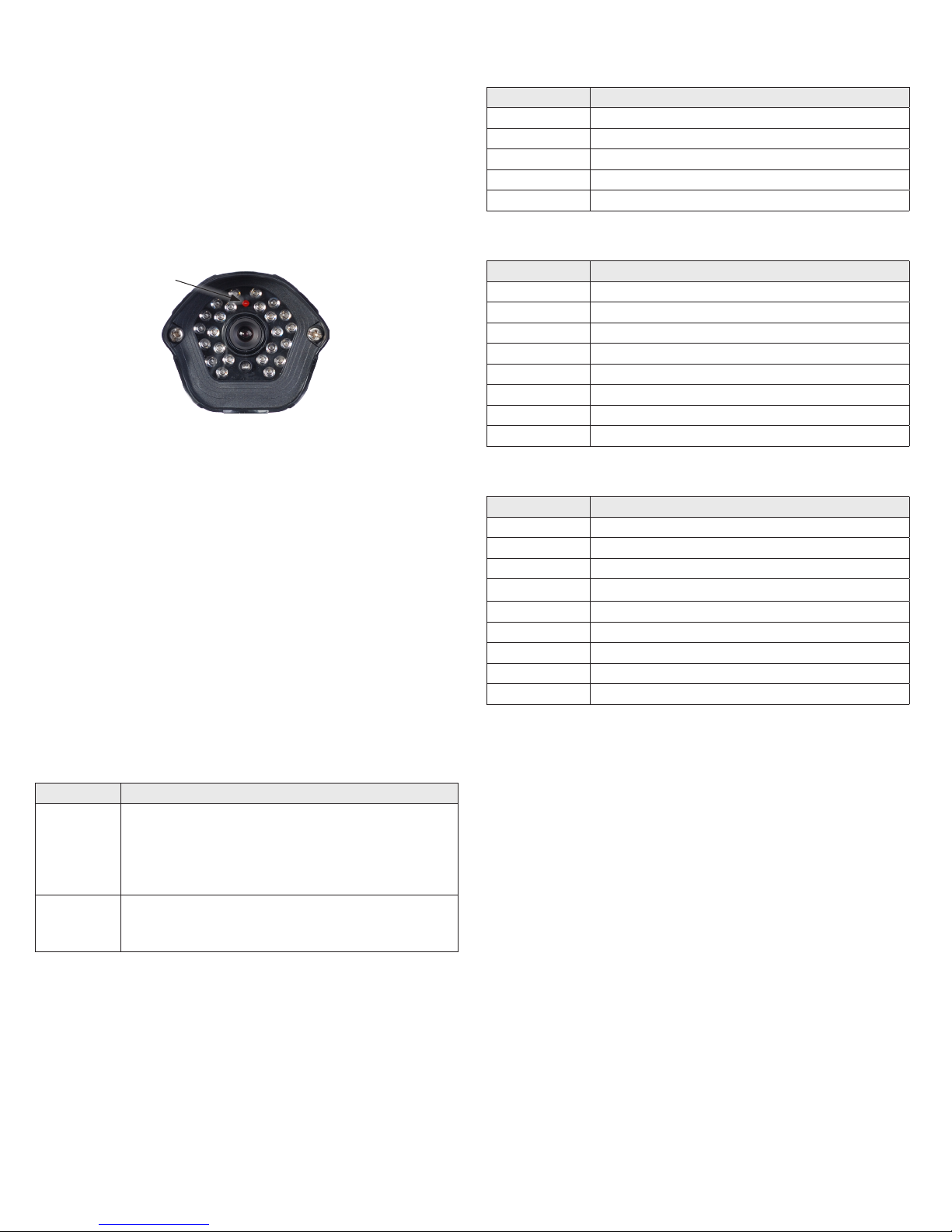
POWER LED
NOTE: After powering o either unit , wait about 10 seconds before powering it on again.
Multiple c amera - receiver sy stems
In a multiple camera - R X module systems, placed the R X modules at least 1 foot apar t. PAIRing can be
perfor med by powering on each camera and R X module system one at a time and waiting until they
PAIR. If PAIRing is lost betwe en one camera and RX module system, it can be re- established by powering
o, then powering on either the camera or R X module of the system, then allowing them to PAIR
automatically.
Manual PAIRing
If PAIRing was not achieved automatically (no video signal f rom the receiver module), it can be manually
initiated by pressing and holding the PAIR button on the camera and/or RX module for 5 seconds. The
POWER LED will ash for about 10 seconds, then remain on continuously when t he units are PAIRed.
The PAIR button on the c amera is located on the back of the uni t beneath a rubber cap. On the RX mo dule,
the PAIR button is located on the top of the unit.
Item Speci cation
Transmissi on channels 80 channe ls, auto selec ted
Video bi t rate Up to 12 Mbps
ID codes Up to 4 M
Video re solution 720 x 480 @ 30 fps (N TSC)
Operat ional range 500 ft ( line of sight)
Specic ations - camera
Item Speci cation
Operat ing frequenc y 2.4000 GHz – 2.4835GHz
Transmit pow er 100mW (maximum)
Modulati on 16 QAM / QPSK / BPSK
Antenna Omnidirect ional
Power consu mption 1.9 W
Voltage 12 VDC / 1A
Dimensio ns 5.12” x 2.76” x 2.28” (130mm x 70mm x 58mm)
Weight 21.87oz (620g )
Specic ations - RX module
Item Speci cation
Operat ing frequenc y 2.4000 GHz – 2.4835GHz
Receiver s ensitivit y -8 0dBm minimum
Video ou tput level 1 ± 0.2 Vp-p @ 75 Ω
Audio out put level 1 ± 0.2 Vp-p @ 60 0 Ω (stereo) (NOTE: t he MVL24CM doe s not provide an au dio signal.)
Antenna 3 dB, omnidirec tional
Power consu mption 1.9 W
Power suppl y 5V / 1A
Dimensio ns 2.99” x 2.876” x .94” ( 76mm x 73mm x 24mm)
Weight 2 .89 oz (82g)
Troubleshooting
Proble m Possib le Solution s
• Check power and A/ V cable connections.
• Verify that the camera and RX module are powered on.
No video
• Verify that the re cording/video monitoring equipment is functioning properly.
• Verify that the POWER LEDs are lit constantly. If the POWER LEDs are ashing,
use the procedure above to PAIR the units.
• Adjust the orientation of the camera and RX module antennas.
Interf erence in video
• Move the equipment away f rom devices that emit high radiation, such as
microwave ovens, wireles s phones, etc.
www.supercircuits.com
2
© 2011 Supercircuits, Inc. All rights reserved.
 Loading...