

Page 1
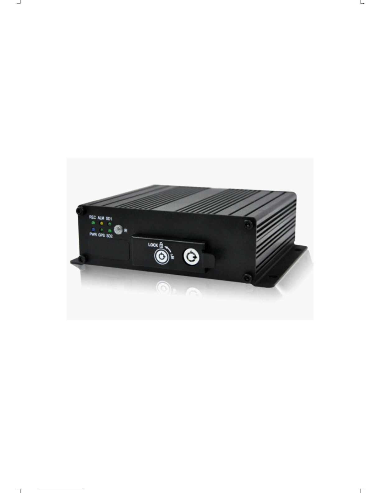
MDVR50 Mobile DVR
User Manual
V1.07E
V1.07E
Page 2
CHAPTER 1:PRODUCT APPLICATION AND PARAMETER---- -------- -------- ----------------------CHAPTER 2:PRODUCT INTERFACE DEFINITION AND FUNCTION DESCRIPTION-- ---------- -- -
2.1:MDV R Out-design and Dimension-------------------------------------------------- --------
2.4:Brief instructio n of commonly used interface cable------------------------------- ------
2.6:Instructions of function keys on re mote controller------- -------- -------- ------- ----- --CHAPTER 3: ------- -------- -------- -------- -------- -
3.1:Demo working and user login---------------------------------------------------------------
3.2:System menu construction chart- -------- -------- -------- -------- -------- -------- ----------
3.3:System setup------- -------- -------- -------- -------- -------- -------- -------- -------- -------------
3.3-1:B asic- -------- -------- -------- -------- -------- -------- -------- -------- -------- -------- ----------
3.4: Recording setup---------------------------------------------------------------------------- ----
3.4-1 :N ormal setup----------------------------------------------------------------------------- ---
3.4-2 :C hannel setu p-------------------------------------------------------------------------------
3.4-3 :Timing setup -------- -------- -------- -------- -------- ----------------------------------------
3.5 :Vehicle information---------------------------------------------------------------------------
3.5-1 :Sensor setup-(alarm input)----- -------- -------- -------- -------- -------- -------- ---------
3.5-2 :G -Sensor setup-----------------------------------------------------------------------------
3.5-3 :Speed s etup---------------------------------------------------------------------------------
3.6: TOOLS--- -------- -------- -------- -------- -------- -------- -------- -------- -------- -------- ---------
3.6-1:F ormat disk manageme nt----------------------------------------------------------------
3.6-3:M otion detection--------------------------------- -------- -------- -------- -------- ----------
3.6-4:S ystem upgrade----------------------------------------------------------------------------
3.7 MODULE MANAGE----- -------- -------- -------- -------- -------- -------- -------- -------- ---------
3.7-1:PTZ set up--------------------------------------------------------------------------------- ---
3.8 :System info rmation---------------------------------------------------------------------------
3.9 :Recording p layba ck----------------------------------- -------- -------- -------- -------- -------CHAPTER 4: COMMON SHORTCUT SETUP------- -------- -------- -------- ---------------------------
4.1 :Cables testing and power on-------- -------- -------- -------- -------- -------- -------- --------
4.2 :Recording setup----------------------------------------- -------- -------- -------- -------- ------
4.3 :PTZ connect ion and setup--------------------------------------------------------------- ---- 22
APPE NDIX 1 : FAQ --------------------------------------------------------------------------------- APPE NDIX 2 : STORAGE SPACE REQIREMENTS-------------------------------------------------
SYSTEM MENU SETTING INSTRUCTIONS
Contents
1
4
4
5
5
7
8
8
9
9
10
10
1 1
11
1 2
1 2
1 3
1 3
1 3
1 4
1 4
1 4
1 5
1 5
1 6
17
1 7
18
1 8
2 0
2 0
20
2 3
2 4
25
Page 3
1.1 The MDVR-50 is a function extensibile, device designed for on-board video
monitoring and remote monitoring, It employs an embedded Linux platform, combined with the
most advanced H.264 video compression / decompression technology and GPS.
With an SD an card for storage, the MDVR can perform many functions such as
audio-video recording, vehicle's driving information recording and remote m
anagement.
With central control software, it can realize the central control of alarm linkage, remote
management and playback analysis.
With a simple and modern appearance, the MDVR
is vibration-proof and installation-friendly, with advanced features.
CHAPTER 1: PRODUCT APPLICATIONS AND PARAMETERS
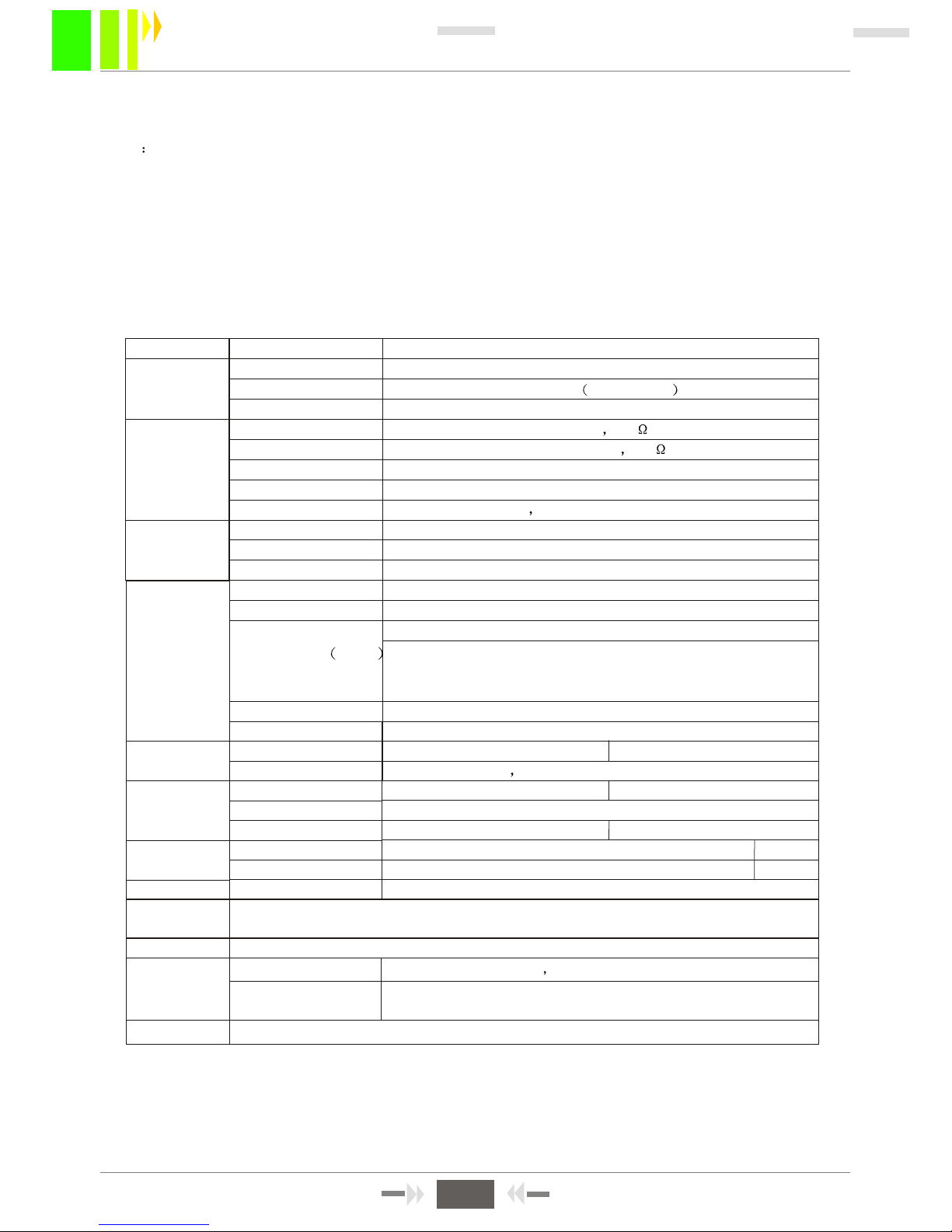
FORM 1 : MDVR PRODUCT'S SPECIFICATION PARAMETERS
1
Items
System
Video
Parameters
Language
OSD
Password
Video input
Video output
Preview
Recording Rate
Image Compression
Audio input
Audio output
Recording mode
Video format
Video stream
Specifications
Chinese/English
Graphical User interface OSD menu
Users Password/ Administrator Password
4CH VIDEO INPUT 1.0Vp-p 75
1CH VIDEO OUTPUT 1.0Vp-p 75
1 CH/ 4 CH Preview.
PAL 25 Frame/s NTSC 30 Frame/s
H.264 Main profile 100fps/s
4-CH
2-CH
Audio & Video sync.
D1/HD1/CIF
ISO14496-10
D1: 2048Kbps ~ 400Kbps
Audio
Audio Bitrate
Storage
Alarm input
Alarm output
Rs485 Interface
RS232 Interface
control panel
Audio power amplifier
Not available.
Built-in GPS module, geographic co-ordinates, speed can be read in coding
flow, and can be wireless uploaded.(optional)
Built-in G-Sensor
PC playback
Support SD cards upgrade.
HD1: 2048Kbps ~ 380Kbps
8 levels optional. Highest: level 1
8KB/s
Supports 1 or 2 SD cards, maximum 32GB for each.
6 alarm input 2 alarm input
2 alarm output, high level 12V output
Support 2-RS485 interface Support 1-RS485 interface
Support 1-RS232 interface
Connect to station reporter or control panel no
Support 2-ch audio power amplifier output no
Video playback on PC and analyze the vehicle info file
Alarm
Communication
Port
Extended
interface
WIRELESS
GPS
G-SENSOR
Software
Upgrade
Video Rate kbps
Image
processing &
storage
MDVR-50 User Manual
CIF: 1536Kbps ~ 128Kbps
Page 4
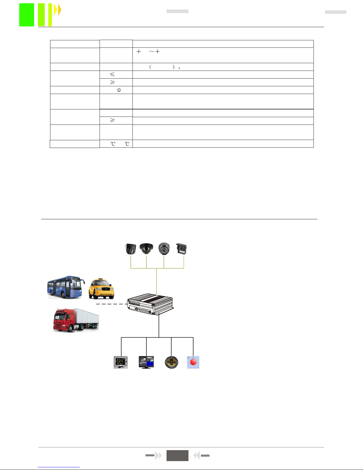
FORM 2 : MDVR BASIC ELECTRICAL PARAMETERS LIST
1.2 MDVR PRODUCT APPLICATION CONNECTION SCHEMATIC DIAGRAM
Figure1-1, MDVR can be used both in common and special vehicles for video monitoring, remote
monitoring, and vehicle positioning. . Vehicles include buses , logistics car, freight car, taxi, tanker,
police car etc. Input acquires signals from a camera through special video line transfer to the MDVR
to process video compression and local storage on an SD card.
A schematic diagram with common applications is shown below.
Functionality depends on the modules installed.
Items
12V
4V
5V
75
<4V
4V
-40 -80
Specifications
8 36Vdc, When long-term under 8Vdc, or long-term
over 36V,auto power off and enter protection mode.
12V +/-0.2V Max:2A.
OFF
On
75Ù for each video input
Input 2Vp-p CVBS analog signal, device input requires 75Ù
impedance
Low level alarm
High level alarm
1.Maximum 32GB for each card.
2.SD card used for storage, support, recording, upgrade, etc.
Well-ventilated enviroment.
DC8-36V
2Vp-p
o 1/ 2 SD cards
Power input
Vehicle key signal
Video output Volt
I/O interface
SD-card interface
Operating Temp
Impedance
Power output
Parameters
Figure 1-1
Control Panel
Monitor
Speaker
Alarm
MDVR
2
MDVR-50 User Manual
Page 5

1.3: MDVR NOTICE:
To use your MDVR safely, acquire satisfactory performance, and extend the service life
of the equipment, please follow the instructions below.
1. When you install and operate this equipment , please obey the products guidelines and the
requirements of equipment connected to it.
2.Power supply and equipment ground: Voltage input range of the power source is DC 8V-36V .
Do not apply inverted power. Use local codes to select power wiring. When the equipment is shut
down , it may be charged, so please avoid short circuit . Before connect with other external devices,
disconnection the equipment from the power supply. The input mode of equipment sensor is level
mode. Input voltage below 4V is considered as low level, above 4V and below 30V is considered
high level. Above 30V will damage the equipment. Correctly connect the ground wires of the device
to the vehicle. If you don't use this MDVR for an extended period, disconnect the power source
to extend service life.
3.Humidity requirements: Install equipment in a dry environment. Avoid damp, misty places.
Don't put the equipment where water can drip onto it. Do not touch the device with a wet hand.
Do not stand in water or touch a wet sureface while contacting the equipment; you may be shocked.
4.Installation position:
To extend the life of the equipment, install it in a place with low vibration, such as behind the
driver's seat. The equipment should be installed near the vehicle's ventilation outlet.
Equipment should be at least 6 inches (15 centimeters) away from other objects to assure
good air flow for heat dissipation. Don't install it in an enclosed area, such as car trunk.
The MDVR can be installed on its right side. The external wiring must be anchored properly
and have flame retardant protection; wiring should not be bent or subject to wear and vibration.
Keep the equipment away from heat sources.
5.Equipment safety:
Ensure passengers in the driver can't interfer with or damage the MDVR, camera, wire and
other accessories. Don't install the equipment near other components in vehicle. When you install
equipment components including the MDVR, camera, accessories and wire, ensure they are
anchored properly before moving the vehicle to prevent damage to those components.
Installation notes:
1. Equipment contains the electronic devices, please handle gently during transport.
2. All installation and maintenance must be performed by a qualified professional.
3. Don't installed this product where corrosion from rain or other liquids exists.
4. Installation hardware must be able to support the weight of the MDVR.
5. Keep the MDVR away from the heat sources, dust and strong magnetic fields.
6. Do not put heavy objects on the MDVR.
7. Never expose the equipment to liquids when cleaning the vehicle.
8. Do not connect the output power to devices that are not recommended for it.
9. Keep fingers and other objects away from connectors while operating the equipment.
10. Please do not open the equipment without professional guidance.
11. Don't change any modules in the MDVR when it is is powered on.
3
MDVR-50 User Manual
Page 6

47
162
80
180
5
138
CHAPTER 2 : INTERFACE AND DESCRIPTION OF THE FUNCTIONS
2.1 MDVR OUTER DESIGN AND DIMENSIONS
Figure 2-1
Figure2-3
Function type MDVR dimension and installation holes (double SD card
model), is shown in Figure 2-1
Unit mm
Panel Indicator Light
Description
V-OUT Video OUT
SD1/SD2: Recording SD card
indicator light. Light is on
when the SD card is installed.
REC: Light is on when
recording
GPS: Light is on if GPS installed
POWER: Light is on when the
power supply is working normally
ALM: Light is on when the MDVR
is has an abnormal statusn
WIFI: Not used.
2G/3G: Not used
IR: Infrared sensor is receiving
a remote control signal
Figure 2-2: hold the back of the SD card label side up,
slide the card it into the SD card slot, then pull on the card slot
LOCK : It can be powered on normally only when electricity is
applied to the LOCK gear. Opening the electronic lock when
working will upload the SD card. Delay power off
according to the menu setting.
SD-1 SD-2
Figure 2-2
Push the card protection cap
to the right after it is unlocked
128
5
162
47
80
138
Figure 2-4
Simple type MDVR size and installation hole site
(single/double SD card) is shown in Figure 2-4
Panel Indicator Light Description :
SD1/SD2: Light is on when an SD
card is installed.
REC: Light is on when recording
GPS: Light is on if GPS installed
POWER: Light is on when the
power supply is working normally
ALM: Light is on when the MDVR has
abnormal status
IR: Infrared sensor is receiving a
remote control signal
Figure 2-5
Figure 2-6
Figure 2-7
Use a key to open the LOCK, open the SD card protection cover, as Figure 2-5 , then put the back of the
SD card upside , insert it to the SD card slot, press it into the right place. As Figure 2-6 , finnally , cover the
chassis. Always format new SD cards after installing them in the MDVR.
LOCK:It can be powered on normally only when the electricity is locked to the LOCK gear. In working period ,
open the electronic lock , the system will upload the SD card. Delay power off according to the menu setting.
Unit mm
4
MDVR-50 User Manual
Page 7
1--12VOUT
2--GND
3--A-IN
4--V-IN
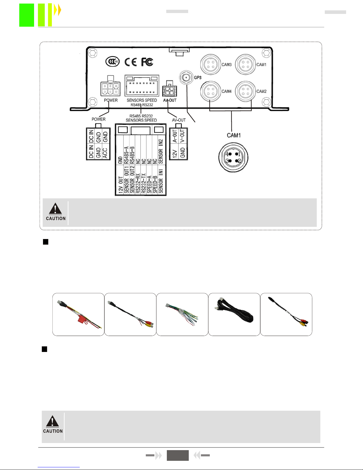
2.3: DEFINITION OF SIMPLE TYPE MDVR BACK PANEL INTERFACE
AVIATION HEAD
VIDEO & AUDIO INPUT
Figure 2-9
GPS Antenna
POWER INPUT
VIDEO/AUDIO OUTPUT
1: Interface specifications, please refer to table 3, V-in & A-in with aviation head
2: 2-channel alarm input , 2 channel alarm output, a pair of school interface
2.4: COMMONLY USED INTERFACE CABLES
Power cable:
As the following photo shows, one end has a 6-pin white plug; connect it to the white connector on
backpanel. Connect the red and black wires directly to the car battery. The red cable is connected to
the positive terminal, the black cable is connected to the negative terminal. Connect the yellow cable
to the ignition line. MDVR equipment starts automatically after starting the car with the car key.
Autodelay stops the MDVR after shutting off the car. The yellow cable connects to the wire
where the car key powers on the dashboard lights (the key position before starting the motor).
Power cable
4PIN A/V test cable
Alarm cable
RS485 RS232
SENSORS SPEED
1. Ensure the battery voltage is between 8V-36V before connection. Otherwise, it
will damage the equipment.
2. Before the battery cable is connected, ensure the insulation between the
conductors is sufficient prevent short circuits.
If a functional MDVR has above kinds of accessories, the 4-pin test cable is only used during
the test; please do not use it for the installation. When installing equipment, to use the 4-pin
audio extention cable. Function model MDVR uses the 4 PIN-AV cable when connecting to the
audio input. Do not use this cable for video only input. Use the AV interface on the front panel
only. To use GPS, a GPS antenna must be installed.
Video cable of the simple MDVR is aviation head
; there
are
some differences between the
corresponding
interfaces. See Figure 2-11.
4PIN A/V cable
4PIN-AV OUTPUT
Audio/video cable
Figure 2-10 Functional MDVR interface roughly matched wiring
5
MDVR-50 User Manual
Page 8
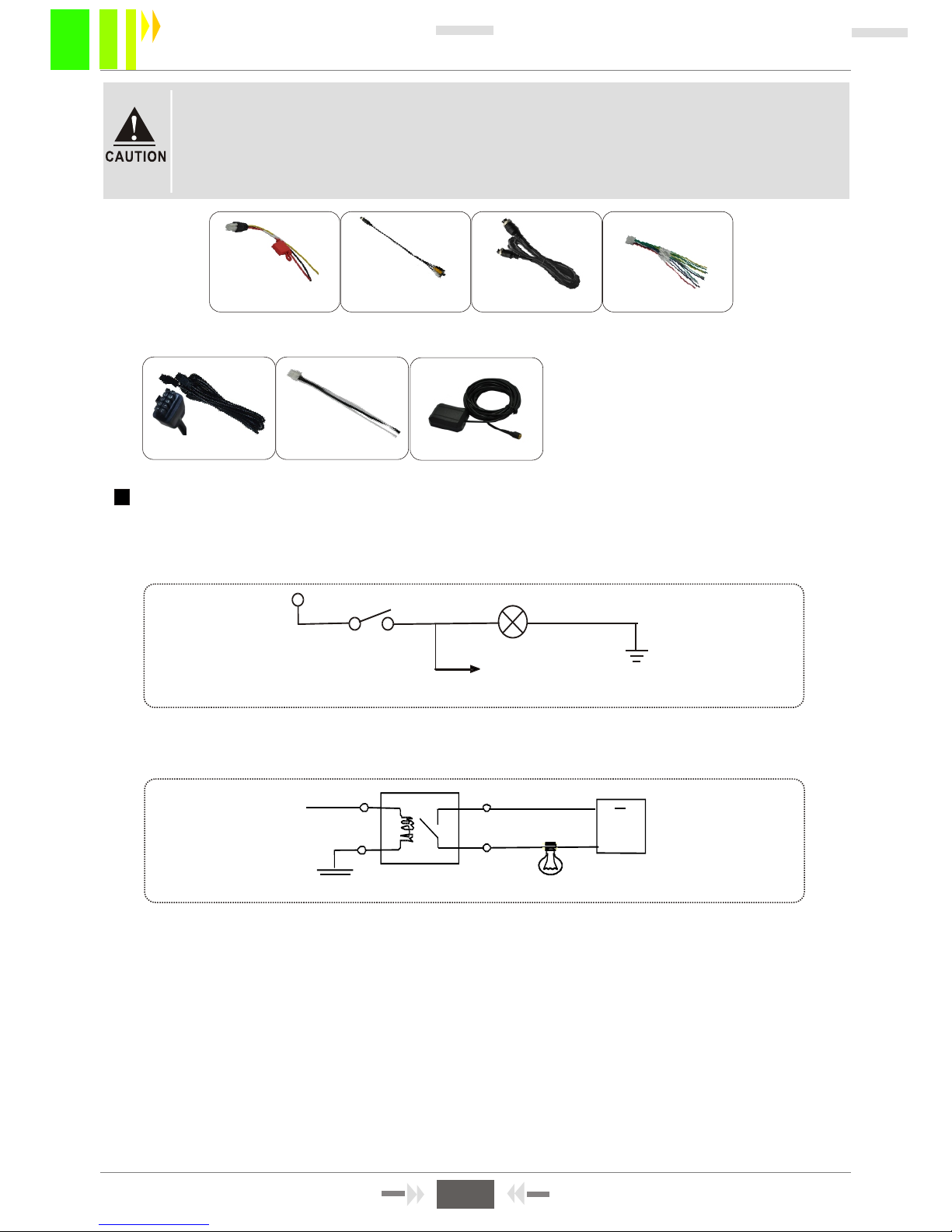
Alarm outputs are voltage level outputs, The output drive maximum is 200 mA. To power larger
devices, you must connect them to external relays. Below is the optoelectronic alarm wiring
diagram for anMDVR alarm output.
+24V
MDVR alarm output
MDVR SENSOR
Braking light
+12V
Brake switch
Figure 2-13
Figure 2-14
1
2
3
4
Alarm input and output
This equipment has six alarm input interface and two alarm output interface (simple MDVR has
two alarm inputs). Alarm input detection is voltage level detection. It can connect to various
vehicles driving status such as brakes, turns, door switches, emergency buttons, etc. When you
press the brake pedal, the MDVR can detect a high level or low level voltage.
EXTENSION
SPEAKER
Power supply cable
RS485 RS232
SENSORS SPEED
AVIATION HEAD
A/V test cable
AVIATION HEAD
A/V cable
FIGURE 2-11 SIMPLE TYPE MDVR INTERFACE MATCHED CABLE.
FIGURE 2-12 MDVR USES CORRESPONGDING CABLES ACCORDING TO FUNCTIONS
Alarm cable
3. The yellow cable must be installed on the ignition line to support the delay
shut down. Otherwise, the last video recording may be lost.
4. The MDVR must receive power directly from the battery. Don't use iron wire
for the ground line; it may produce a negative pulse that will jam the normal
operation of the processor. Use wire of 1.5 mm or larger to power the MDVR.
6
MDVR-50 User Manual
GPS antenna
Page 9

Power on /power off
LOGIN
INFO
Figure keys 1, 2, 3, 4
RETURN
PAUSE/STEP
GOTO
FRAME
PLAY
Forward
REW
Stop REC
Recording
NEXT
PREV
PTZ
NOTE: Tthis function is not used temporarily
If a password is set in the MDVR, press LOGIN key, then enter the password. The system does
not have a recovery and reset function, so please remember the password.
Information
Under the surveillance images, it can be used to switch between single and four images
Press the image segmentation key to show the 4 images; under the surveillance image,
press this key ; it will show switch sequence as follows: CH1-CH2-CH3-CH4.
Exit to the last sub menu. Lastly, return to the menu setting and the surveillance images
Suspend key and single step key when playback video material. Press the key once to
play one step. Press the play key to return to the normal playing speed
Playing back , it can jump to point time to start playing
Press this key to frame
Press to play
Press the forward button during video playback. There are four speeds:2X,4X,8X,16X.
Press the rewind button during video playback. There are four speeds: 2X, 4X, 8X, 16X
Stop manual video record button
Start manual video record button
During play, go to the next page/next file;
During play, go to the last page/last file;
Automatic, preset, adjustment, variable times +, variable times-, focus +, focus-, aperture +,
aperture-, PTZ PRESET RECALL BRUSH
F1 F2 F3
F1 is shortcut key , F2, F3 is spare key
LOGIN
Power on /off
(mpt used)
System information
Number key area
Exit / return
Picture adjustment
PTZ control
Direction key area
Play back operation key area
4 images segmentation
PTZ control key area
Shortcut key / test key
Delete / cancel
2.6 INSTRUCTIONS OF FUNCTION KEYS ON REMOTE CONTROLLER
7
MDVR-50 User Manual
System information
Page 10
CHAPTER 3 SYSTEM MENU SETTING INSTRUCTIONS
3.1: DEMO WORKING AND USER LOGIN.
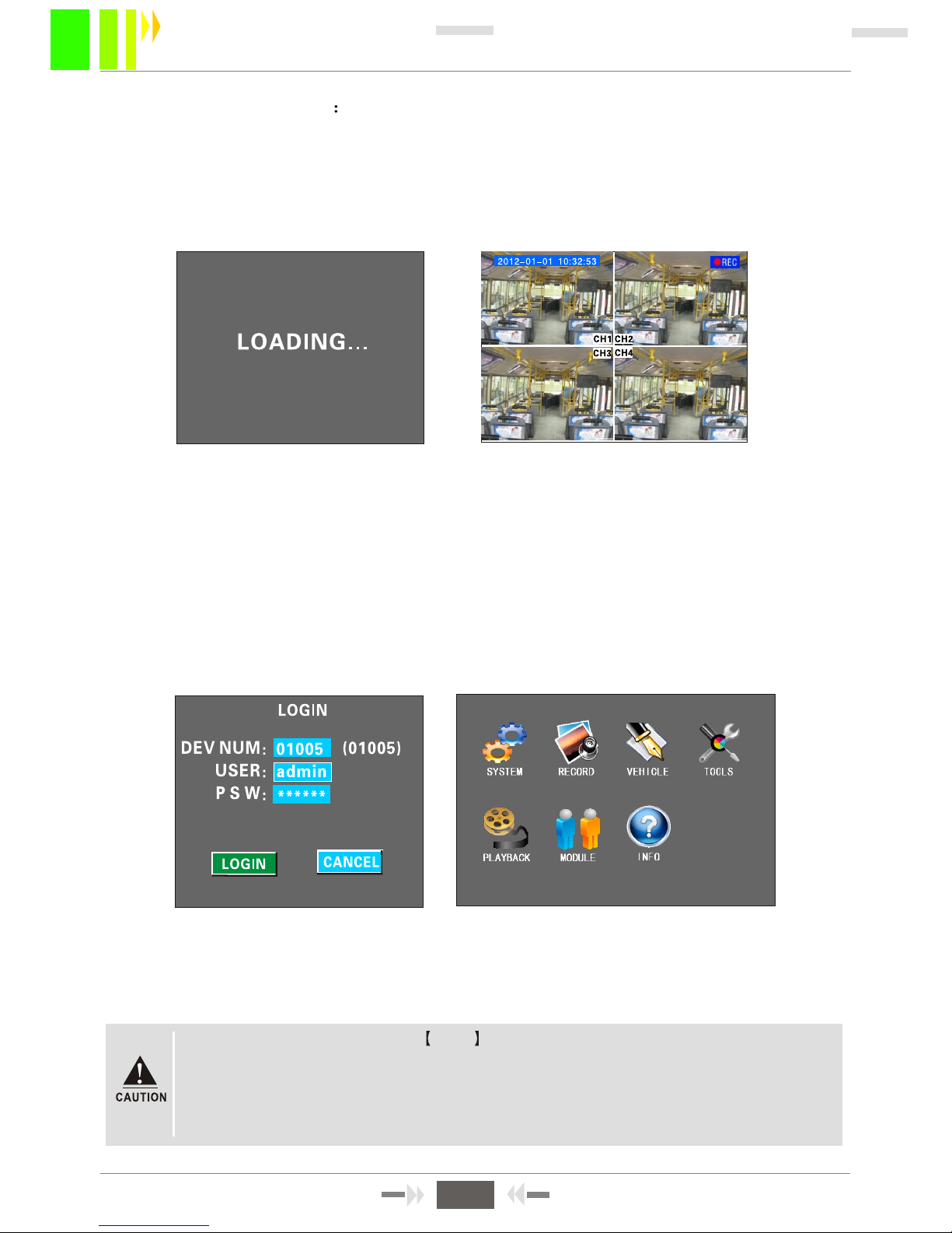
Power on the MDVR after the power supply and other connecting devices are powered on.
Always follow installation guidance. After Loading, a four-image monitoring interface appears.
Press the remote control LOGIN button to open the login interface. See Figure 3-3.
INSTRUCTONS:
:
"" " "
""
DEVICE NUM: Set number for every device.The number will appear to the right of the number input
box. Enter the number as shown, one number only for one device.
USER NAME: Including admin or normal user name. normal users have permission to open video
searching, playback, information and other menus, but cannot set the menu elements or data. Admin
users have permission to modify system parameters.
PASSWORD: Enter the password for user name entered. When the password is correct, press the
down button to select LOGIN, then press ENTER to log in. If the password is incorrect, press
CANCEL and delete, then enter the correct passwo
rd. The password for admin is 111111. The
screen shown after entering password is shown in Figure 3-4.
Figure 3-1 Figure 3-2
The system includes seven submenus: SYSTEM, RECORD, VEHICLE, TOOLS, PLAYBACK,
MODULE, and INFO. Main menu is shown in Figure 3-4.
Figure 3-3 Figure 3-4
1. All submenu settings must save to be in effect. Otherwise, no change occurs.
2. A filled check box indicates selected. Not filled means function not selected.
3 Enter number inputs using the number buttons on the remote control, or enter
them directly with the soft keyboard. Lettersare entered with the soft keyboard
only. Press the RETURN button to go to the previous menu/page.
""
8
MDVR-50 User Manual
Page 11
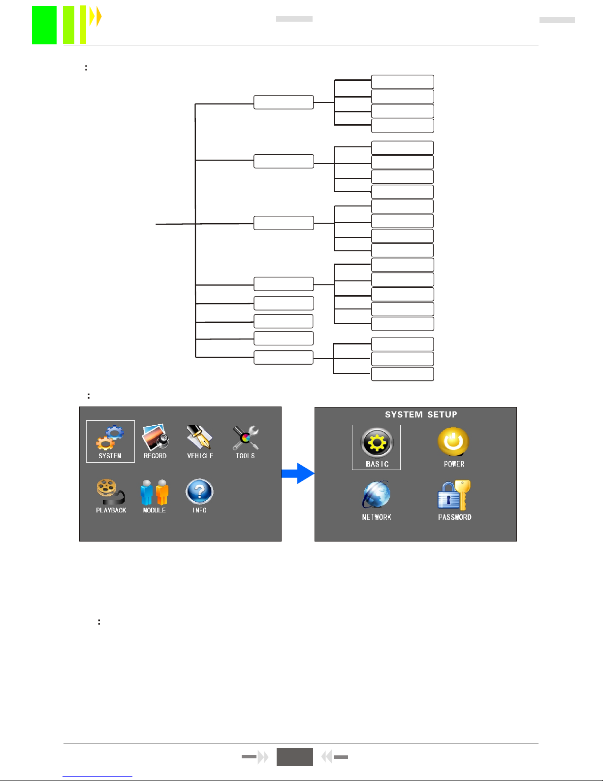
3.3 SYSTEM SETUP
The SYSTEM submenu includes BASIC setup, POWER setup, NETWORK setup (not used), and
PASSWORD setup.
3.3-1 BASIC SETUP
Basic setting: Basic setup is used for setting system time and other basic function setting.
1. DATE FORMAT: Press ENTER to type Y-M-D/ D-M-N.
2. DATE AND TIME Setup: Press ENTER, and then press "-" or"+" to set the data, press ENTER
to confirm.
3. During operation timeout (can set from 30-3600 seconds) and device number modification, press
CANCEL to delete, and then press the number button.
Figure 3-6
Figure 3-7
BASIC
POWER
NETWORK
PASSWORD
NORMAL
CHANNEL
TIME LIS T
SENSOR
SPEED
G-SENSO R
FORMAT
CINFIGURE
UPGRADE
LOG
DETECTION
SYSTEM
RECORD
VEHICLE
MODULE
INFO
SHORTCUT
PLAYBACK
LOGIN
TOOLS
3.2 SYSTEM MENUS CONSTRUCTION CHART
SUB-STREAM
TEMPERATURE
Figure 3-5
9
MDVR-50 User Manual
Page 12
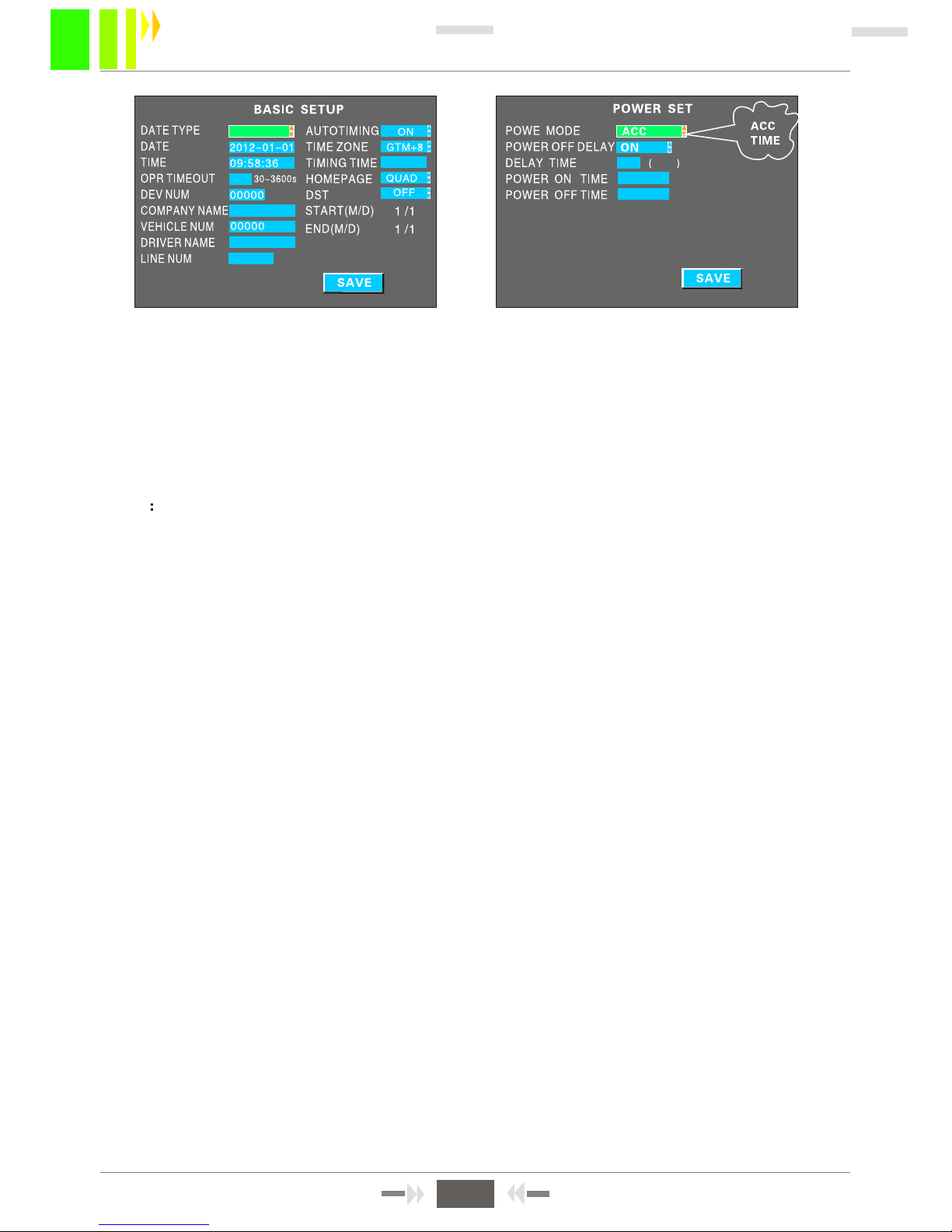
1. Power on/off mode: Select from TIME /ACC mode, and press ENTER to save the setting.
ACC mode means when the vehicle powers on, the device will start (recommended). In TIME
mode, the device will power on and power off at fixed times.
2. Delaying off setting: When you select ACC mode or TIME mode, you can set the POWER OFF
DELAY (ON/OFF) and the delay time (3-240 min). Click SAVE to retain the settings.
3.3-2 POWER OFF/ON SETUP
4. "COMPANY NAME", "VEHICLE NUM", "DRIVER NAME""LINE NUM" Setting: Press ENTER to
open the keyboard window, then use left/right/up/down/enter keys to enter the values.
5. HOME PAGE: Two options are availabe: "DEV STA" and "QUAD". QUAD open the normal
monitoring screen when the device is turned on. If DEV STA is selected, system information wil
appear in the four normal screens. It is equal to the function when the INFO button is pressed.
6. When the autotiming function is ON, the system will adjust the time via GPS automatically at the
time for adjustment (TIMING TIME).
Figure 3-8
YMD
30 ( )
06:00:00
Figure 3-9
5 MIN
06:00:00
22:00:00
10
MDVR-50 User Manual
Page 13
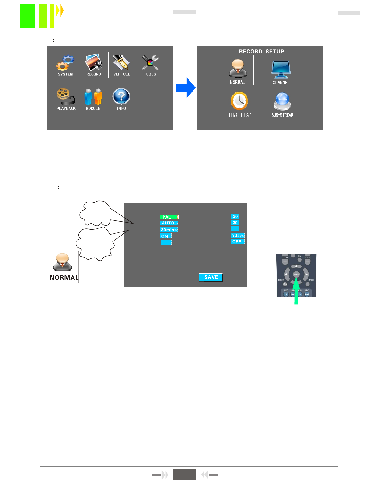
3.4 RECORD SETUP
RECORD includes: NORMAL setting, CHANNEL setting and TIME LIST setting.
It can acheive the highest quality recording after settings. With default settings, the device
will start recording after being powered on. But in order to reach better recording function, you can
modify the related parameters. The RECORD menu is shown in Figure 3-13.
Figure 3-12
Figure 3-13
1. TV SYSTEM: Press ENTER to select PAL/NTSC system. NTSC is a video standard in the USA.
2. REC MODE: Press ENTER to select Auto/ Alarm/Timing mode.
3. PACKET TIME: It is the duration of a recording that is packed into one file. Select either 15/30/45/60
minutes. Options 15 and 30 minutes are recommended.
4. Automatic recording overwrite can be selected ON or OFF. If ON and the SD card is full, the next
recording will overwrite the first recording automatically (FIFO).
5. ALARM PRE-REC TIME(S): When an alarm occurs, it will prefix the period before the alarm to the
Alarm recording. (range 0-60 seconds)
6. ALARM REC DELAY(S): After the alarm stops, it will continue to record for a period and append it
to the alarm recording.
7.ALARM OUTPUT TIME(S): This option sets the alarm output time delay when alarm occurs and
connects to the output device.(range 5-240 seconds )
8. REC PROTECH TIME: This option sets minimum life of a recording stored on an SD card. When the
SD card is full, the recording will not be overwritten. Press ENTER to select either 1/3/5/7/10/15 days.
9. REC VEHICLE INFO: Select ON/OFF. When ON, recordings will contain all the alarm, GPS and
other information which can be viewed via playback software.
10. 1-15 Optional.VOLUME OUT:
3.4-1 NORMAL SETUP
Figure 3-14
During settings modification, select menu, then press ENTER to switch, or press
ancel before entering numbers.
"C "
AUTO
TIMED
ALARM
15mins
30mins
45mins
60mins
1-15 days
NORMAL SETUP
SYSTEM:
REC MODE:
PACKET TIME:
OVERWRITTEN:
ALM PRE-REC TIME(s)
ALM REC DELAY(s):
ALM OUTPUT TIME(s)
REC PROTECT TIME:
REC VEHICLE INFO:
15
11
MDVR-50 User Manual
VOLUME OUT:
15
Page 14
00:00--23:59 00:00--00:00
00:00--00:00 00:00--00:00
00:00--00:00 00:00--00:00
00:00--00:00 00:00--00:00
00:00--00:00 00:00--00:00
00:00--00:00 00:00--00:00
00:00--00:00 00:00--00:00
00:00--00:00 00:00--00:00
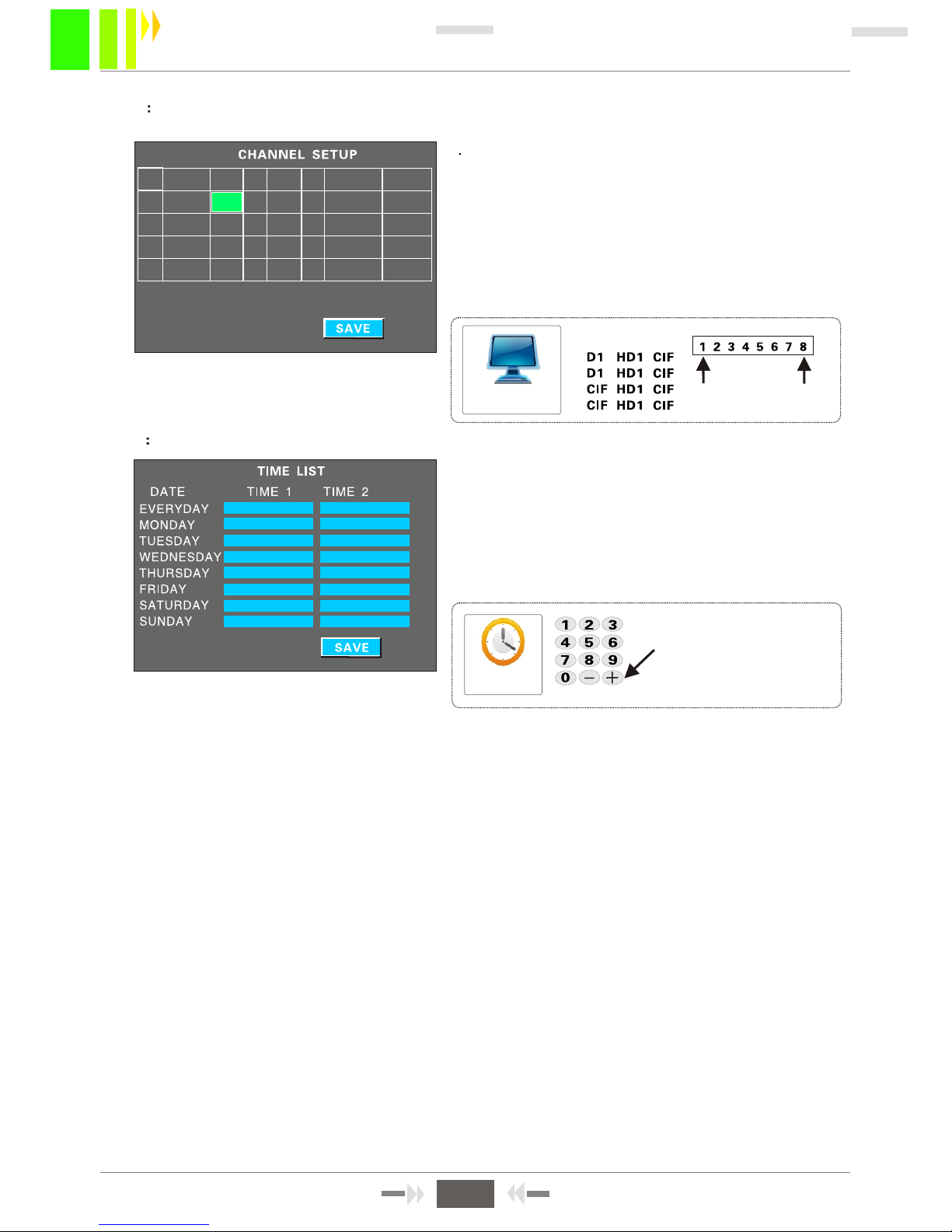
3.4-2 CHANNELS SETUP
1 Set properties for each channel, including RES,
QUAl MIC AUDIO,VOLUME etc .
FPS: 1-25 optional. 25 frames per second is real-time
recording. 1-8 grade QUA optional. Grade 3 is the
default. 1 is the highest, 8 is the lowest. If some
channels do not need video or audio recording, turn
them off to save the storage space.
MIC: Must be set "ON" to record and monitor audio.
3.4-3 TIME LIST SETUP
INSTRUCTIONS:
1.See Figure 3-14 in REC MODE. Select
"TIME LIST " mode, then set the time for recording.
Move to the time field, then press plus or minus
key and move to the numbers that need setup.
Setup each time using the number keys.
Time list
Figure 3-15
Figure 3-16
Cursor move to the
time, then press plus
and minus key to
operate
CHANNEL SETUP
RES.
QUA
HIGH
LOW
CH ENABLE RES. FPS QUAL MIC PREVIEW VOLUME
CH1 ON D1 25 3 ON ON 15
CH2 ON D1 25 3 ON ON 15
CH3 ON CIF 25 3 ON ON 10
CH4 ON CIF 25 3 ON ON 10
12
MDVR-50 User Manual
Page 15
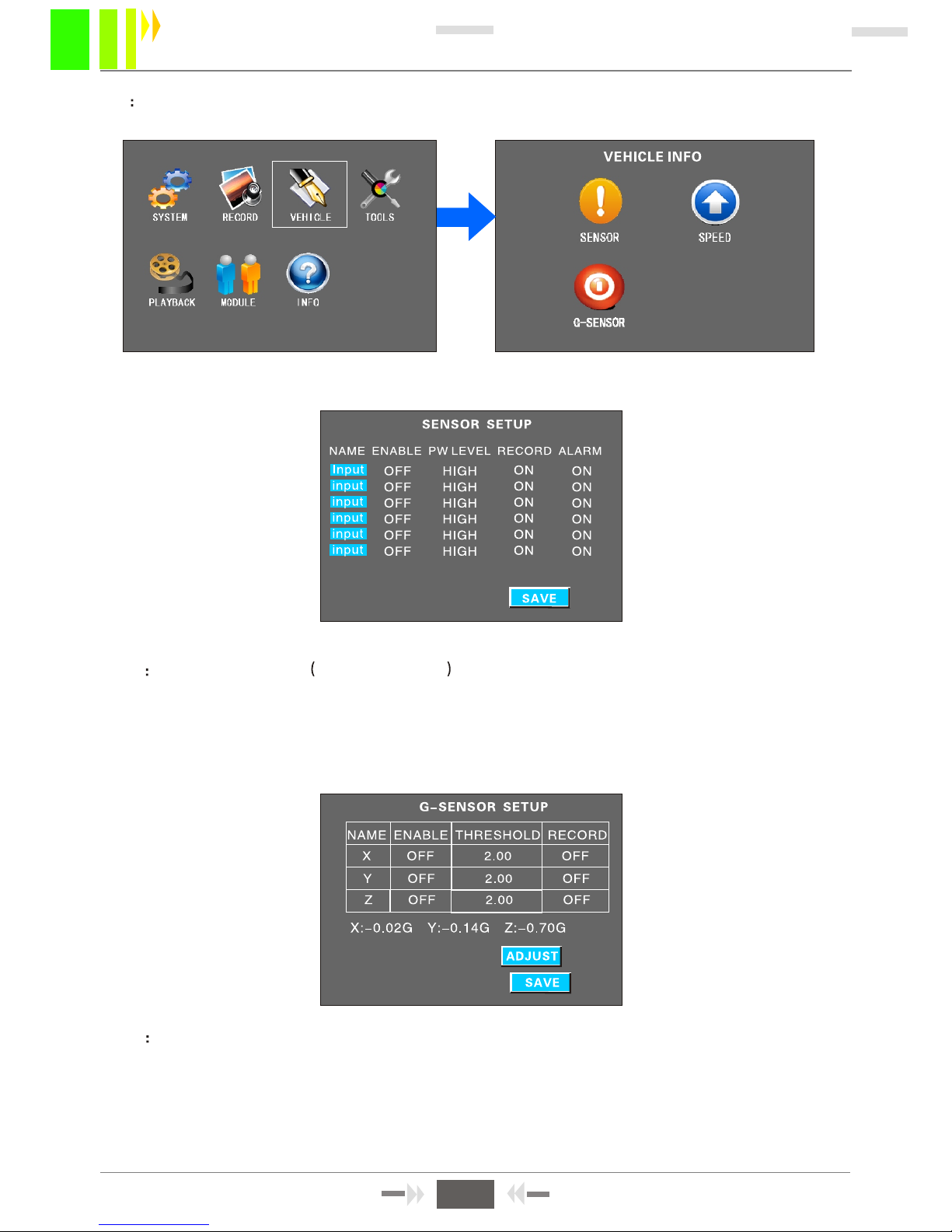
Figure 3-21
G-SENSOR SETUP
SENSOR SETUP
Figure 3-20
3.5 VEHICLE INFORMATION
It includes SENSOR, SPEED, SETUP.G-SENSOR
1. When you install an MDVR, define the sensor name for each port settings. See Figure 3-20.
For instance, change the name "INPUT" to "Front door", "Brakes", etc.
2. "ENABLE" means switching on the sensor. You can select alarm mode as the recording mode,
and then select record and alarm on/off on this menu. A, sensor input is also an alarm input, with
high/low level detection in effect. Normally, above 5V is a high level.
3.5-1 SENSOR SETUP- ALARM INPUT
Figure 3-19
3.5-2 G-SENSOR SETUP
Before you setup acceleration, you must clear the X/Y/Z parameters. Acceleration can be thought of
as a three-dimensional XYZ coordinate axis that expresses three directions: up-down, right-left , and
front-back. Unchanging speed and direction will not affect on it. Acceleration setup is the setup
of thresholds determined through testing. See Chapter 4.3 for more information.
Figure 3-18
13
MDVR-50 User Manual
Page 16
3.6 TOOLS
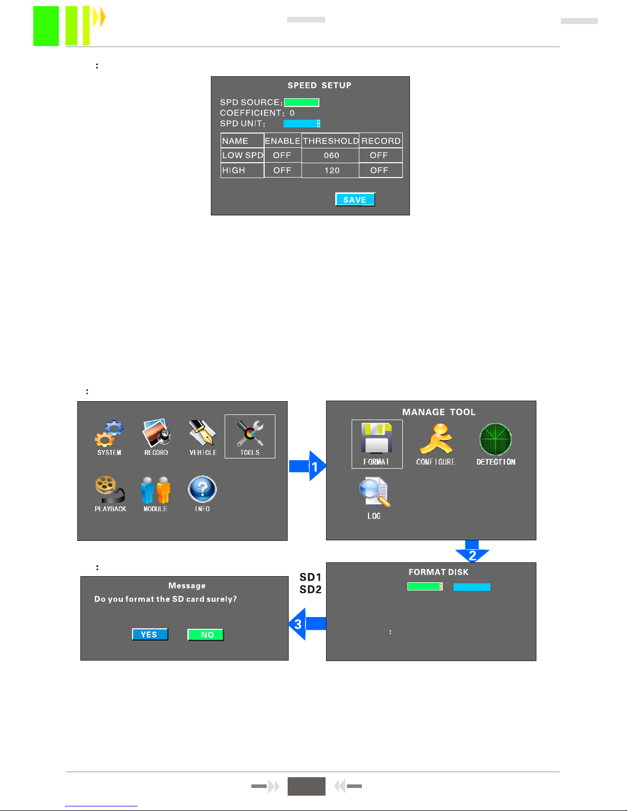
Manage tool including 4 menus: FORMAT, CONFIGURE, LOG AND DETECTION.
3.6-1 FORMAT DISK MANAGEMENT
Refer figure 2-2 or 2-5. Before you turn on device, insert an SD card and format it. Refer to the
pictures above for the format procedures. You can formant the card in either slot SD1 or SD2.
NOTE : All files on the card are erased during format. If important data is on the
card, backup the data before formatting.
Figure 3-23
Figure 3-24
Figure 3-25Figure 3-26
SELECT CARD
SD1
FORMAT
WARNING If you format the sd card,
all of the data will be lost!
3.5-3 SPEED SETUP
Figure 3-22
KM
KM
MPH
14
MDVR-50 User Manual
GPS
VEHICLE
1. If you select GPS to determine vehicle speed, press ENTER. The MDVR must have a GPS module
installed and a good GPS signal.
2. If you select "Vehicle" to determine the speed, a pulse sensor is used to calculate the speed ratio
(coefficient = pulse /speed ). The pulse sensor connects to ports SPEED-A and SPEED-B.
3.Unit of speed (SPD UNIT) is switchable. You can also enable low speed thresholds and high speed
thresholds, and record when thresholds are exceded.
Page 17
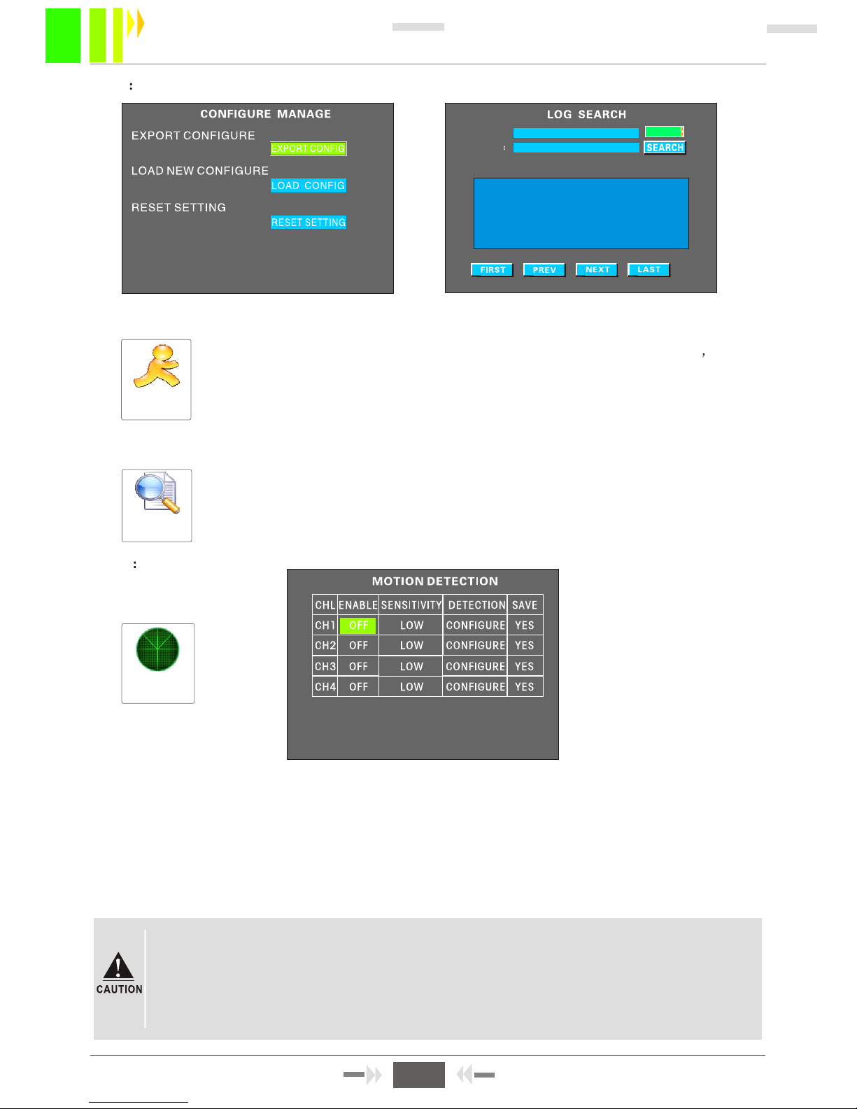
Select MOTION DETECTION in MANAGE TOOL menu to access the motion detection settings.
When moving objects are discovered in the detection area, information is written into the log file
(MD ALARM). If a continuous alarm, or several alarms in 30 seconds, the system will write the
log every 30 seconds. You can view the information under manage tool Log query.
If you set Alarm recording as the recording mode, when motion detection occurs, video during
this period will also be recorded. You can playback this video through an alarm recordings
query.
""
3.6-3 MOTION DETECTION
Figure 3-29
Step1. Enter main menu - select recording setting - manage setting - set alarm recording
as the recording method.
Step2. Set pre-record and delayed time. To maintain good alarm events continuity,
set to 2 minutes or longer.
Step3. Enter main menu - manage tool - motion detection - enable function turns, set
detection sensitivity and detection area, then save,
Motion
Detection
3.6-2 CONFIGURE MANAGE AND LOG SEARCH
Configure manage includes import and export of the current system
configuration. You can also restore the factory configuration. When exporting the
system configuration, the configuration files are stored on SD1. The exported
configuration can be loaded into other MDVRs of the same model.
Restore factory configuration sets all parameters in the MDVR to their
original factory values. This action may be useful when troubleshooting problems.
'
Select the start and end times, and issues types ( ALL/ALARM /USER), then start the
the search. The system will record related information: system power on,
user setting, networking setup (not used), video lost, playback file, motion detection
alarm, system setup, etc.
CONFIGURE
MANAGE
LOG SEARCH
Figure 3-27
Figure 3-28
START TIME
END TIME
ALL
2012-01-15 00:00:00
2012-01-15 23:59:59
DATE TIME EVENT NAME
12/01/15 14:45:07 POWER ON
12/01/15 14:46:55 VIDEO LOST1
12/01/15 14:55:38 FILE PLAYBACK
12/01/15 14:56:25 REC NORMAL SET
15
MDVR-50 User Manual
Page 18
Upgrade
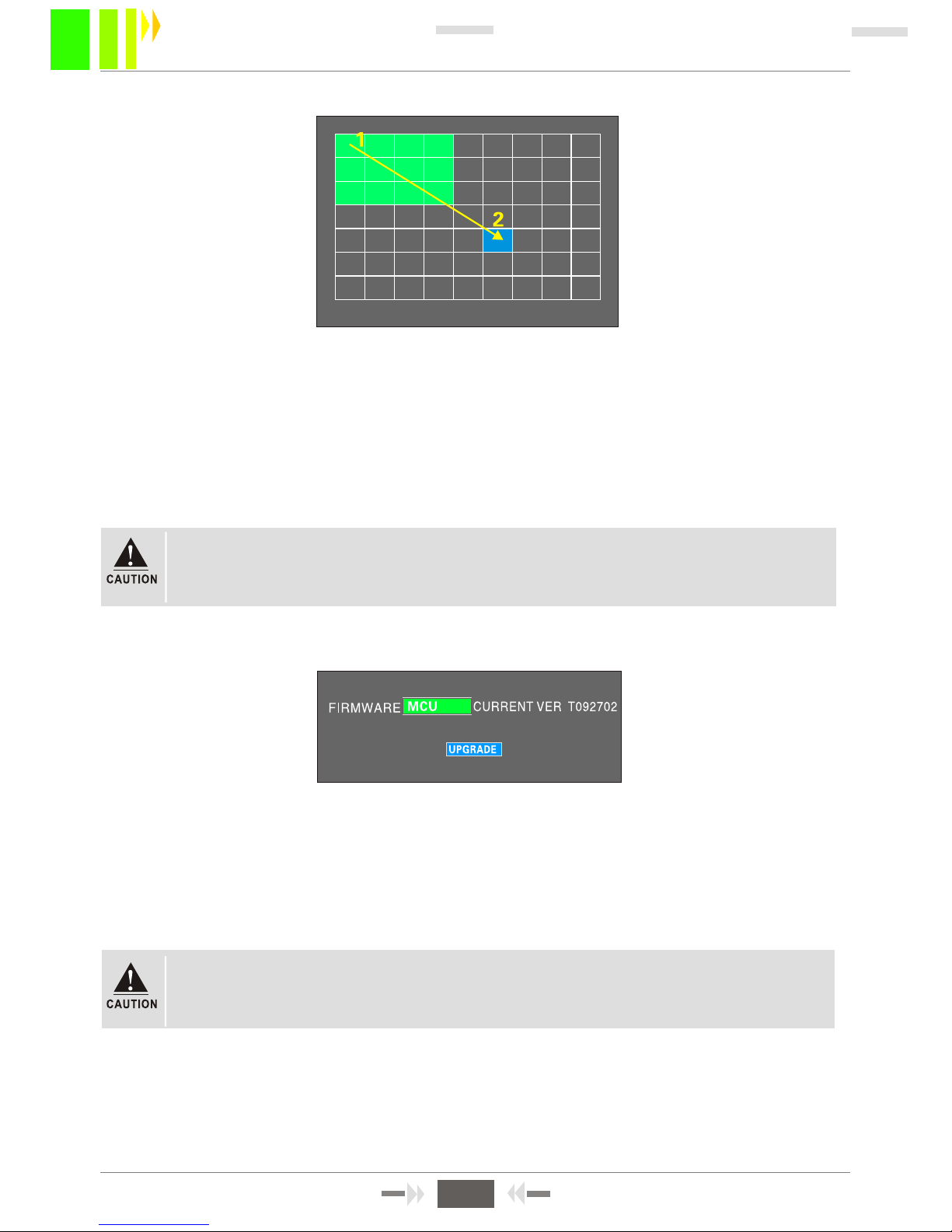
Select CONFIGURE, then press ENTER to enter into motion detection configuration interface. See
Figure 3-30.
Step1: Select the first cell, press ENTER (turns yellow). Move cursor with the arrow keys (turns green)
Step2: Select the second cell. The diagonals between between these two cells is the
selected area. After selecting the area, press ENTER. The diagonal region turns green.
Step3: Press RETURN to confirm the last cell, then save. Sensitivity can be low, medium or
high. In high-sensitivity mode, you will sense changes in light level. In low
sensitivity mode, you can only detect moving objects .
Figure 3-30
Figure 3-31
PROCEDURES OF SETTING DETECTION AREAS:
No effect on this menu , the procedures are as bellowing :
Step1: Copy the upgrade file (named "HI3512-xxxxxxx.crc") onto an SD CARD.
Step2: Insert the SD card into the SD1 slot. Power on the MDVR, then go to "Upgrade"
Step3: Enter into the system after upgrading successfully. Press Key F1 on the remote control to
view the system version information.
3.6-4:SYSTEM UPGRADE
16
MDVR-50 User Manual
"""C"Enter and ancel can delete the selected areas. You must SAVE the
configuration to retain the settings.
Do not power off or remove a USB device while the device is upgrading, otherwise
an unrecoverable system failure may occur.
Page 19
3.7-1 PTZ SETUP
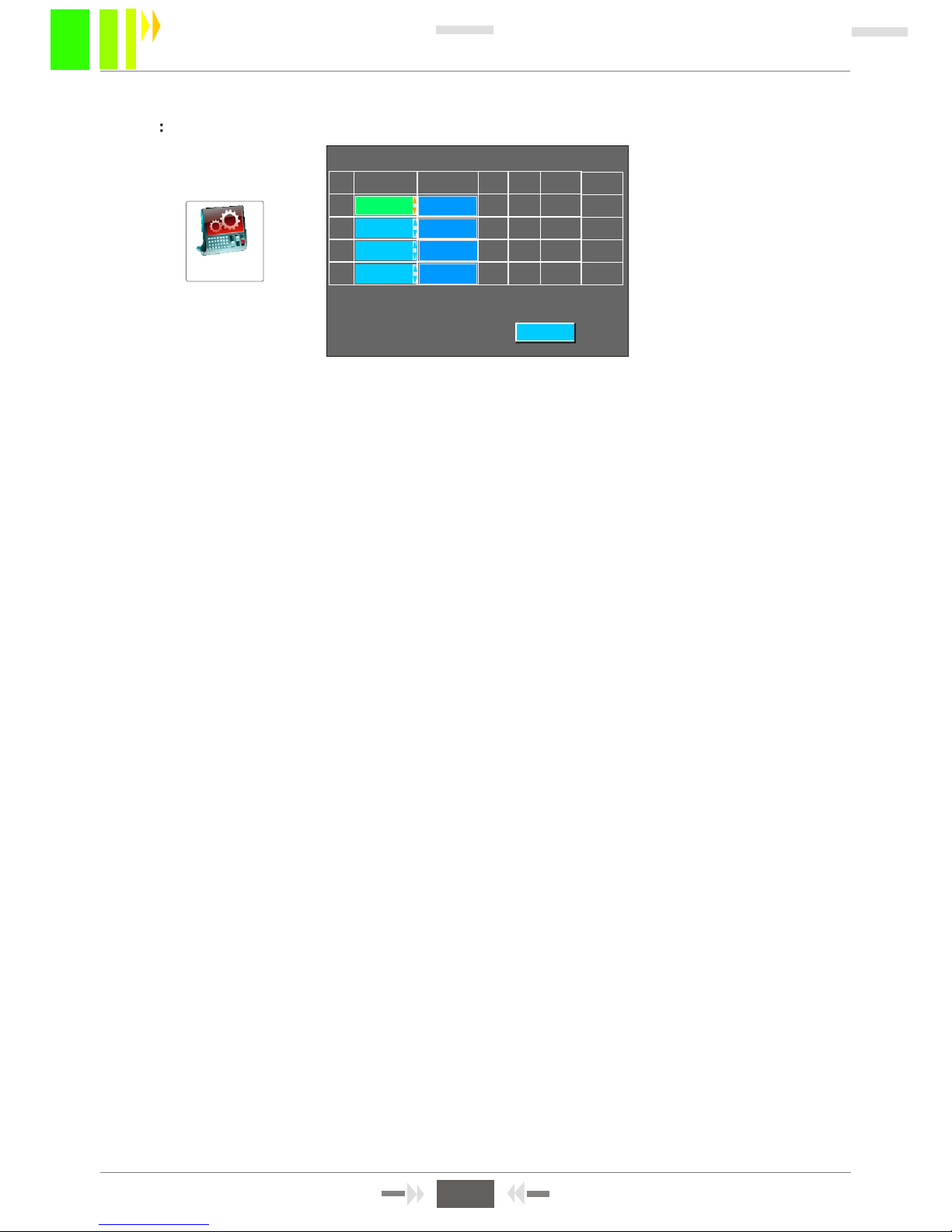
INSTRUCTIONS :
1. Protocol:Set to PELCO-D or PELCO-P.
2. Baudrate: Options are 1200 / 2400 / 4800 / 9600. You can modify communication
settings for individual PTZ devices.
3. D-bits: Normally 8 data bits. Select 1 - 8.
4. S-bit: Normally 1 stop bit.
5. Verify: Select parity checking value or none.
6. Address num: Enter address number set in the PTZ device.
Normally the PTZ device address code is set to 1. If multiple PTZ devices are on the
network, each must have a different address code.
7. Cable connecting: Connect PTZ positive (+) RS485-A, PTZ negative (-) to RS485-B.
'
'""
Figure 3-37
PTZ SETUP
PTZ SETUP
Protocol Baudrate Dbit Sbit Verify Num
CH1 PELCO-D 2400 8 1 None 1
CH2 PELCO-D 9600 8 1 Even 12
Ch3 PELCO-D 9600 8 1 Even 12
CH4 PELCO-D 9600 8 1 Even 12
SAVE
17
MDVR-50 User Manual
3.7 MODULE MANAGE
Page 20
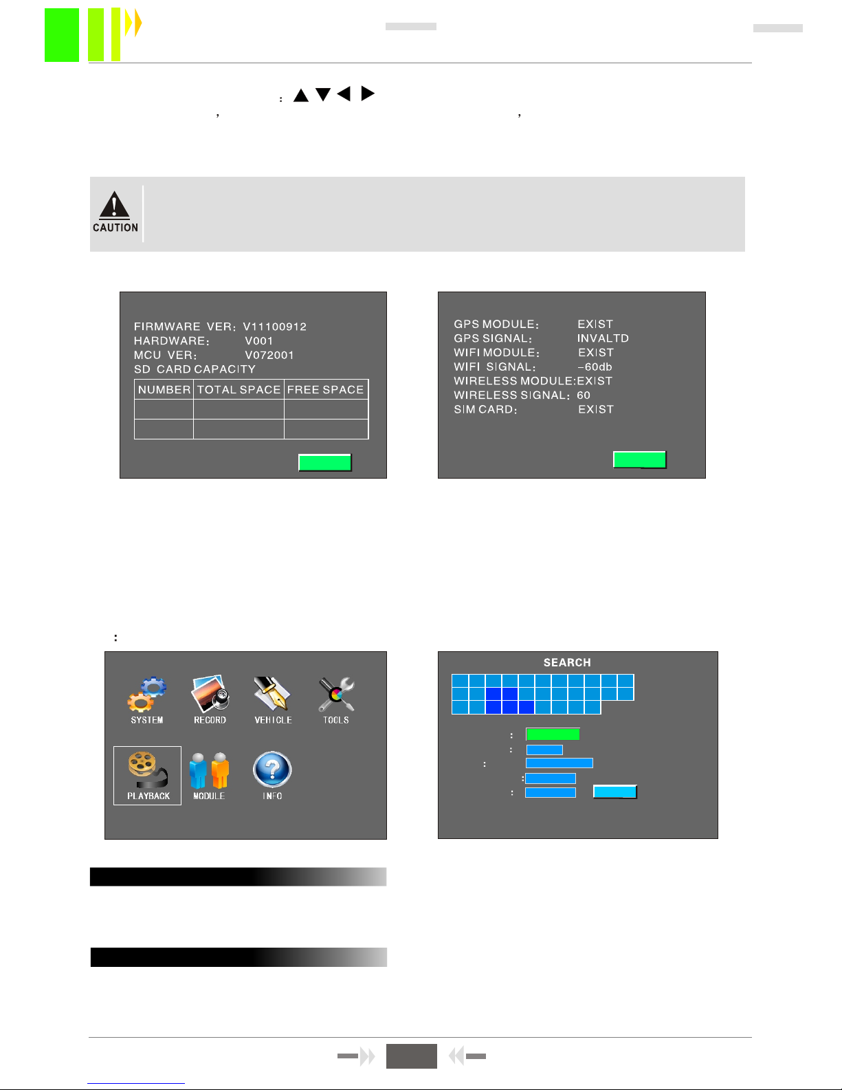
INSTRUCTIONS:
Open the main menu and select INFO, or press F1 on the remote control to display system
to show system information. The system information contains firmware version, software version,
number and SD card storage informations.
ALL
01 0 2 03 0 4 05 06 0 7 08 09 10 11
12 13 14 15 16 17 18 19 20 21 22
23 24 25 26 27 28 29 30 31
REC TYPE
CHANNEL
DATE
START TIME
END TIME
SD1
2011-06-15
00:00
23:59:59
SEARCH
3.9 PLAYBACK
Figure 3-40 Figure 3-41
Enter the recording search menu, select the recording type and storage card to playback.
You can also can search the files according to date and time. When recordings are
available, the date will beome green. Refer to Figure 3-42 for more information.
A:SEARCH INSTRUCTIONS
8. Remote control opertation on the menu are used for controlling up,
down, left and right; ZOOM + and - are enlarge and narrow functions. Focus + and - increase
and decrease focal length. IRIS+ and IRIS- adjust infrared l ights, PRESET is used
to set the preset position. RECALL is used to return to the preset position. RUSH is a wiper.
These function can only be used with PTZ devices.
"
"
"" ""
When connecting to a PTZ device to set parameters, always select the correct
channel for the device. For example, if the PTZ device address is 2, set control
for transfer to device 2.
Refer to Chapter 4 , chart 4.4 for more information.
B:SEARCH RESULTS INTERFACE
Enter the search result interface menu to see recording file information :
Set REC TYPE to "Normal" or "Alarm" recording. Normal recording files usually result from
turning on device recording, or timed recording. Alarm recording is from "Recording setup -
18
MDVR-50 User Manual
Page 21
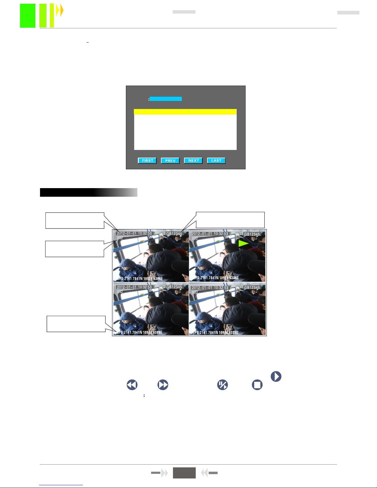
Figure 3-43
C:Playback interface
DATE/TIME
VEHICLE SPEED
VEHICLE NUMBER
COORDINATES
After selected fixed recording file, yellow lights shows selected. Press "ENTER", as figure 3-43,
play procedure can indicate the time, speed, GPS information, etc. The button
is used for PLAY, back REW , FWD , , PAUSE /STEP. , STOP .
For fast forward and rewind, press multiple times to move at X2, X4, X8, X16 times the speed of play.
If audio recording exists, adjust the volume and then press direction button: left and right to adjust
the audio balance. To playback recordings on the SD Card on a PC, see section 4.5.
Figure 3-42
setup Record mode and others menus such as sensor setting, speed alarm setting,
shock acceleration, motion detection setting and related parameters and also connect peripherals.
When an alarm signal occurs, the system will record video. When playing back the recording,
the resolution (D1/HD1/CIF), video's starting and ending time, channel, and size is shown
in the SEARCH RESULT display.
Normal
SEARCH RESULT
DATE
2012-01-01
TYPE RES. START END CHL SIZE
Normal HD1 14:43 14:55 1 29M
Normal HD1 14:43 14:55 2 31M
Normal HD1 14:43 14:55 3 26M
Normal HD1 14:43 14:55 4 35M
Normal HD1 14:55 15:15 1 63M
Normal HD1 14:55 15:15 2 60M
Normal HD1 14:55 15:15 3 58M
Normal HD1 14:55 15:15 4 70M
19
MDVR-50 User Manual
Page 22
CHAPTER 4: COMMON SHORTCUT SETUP
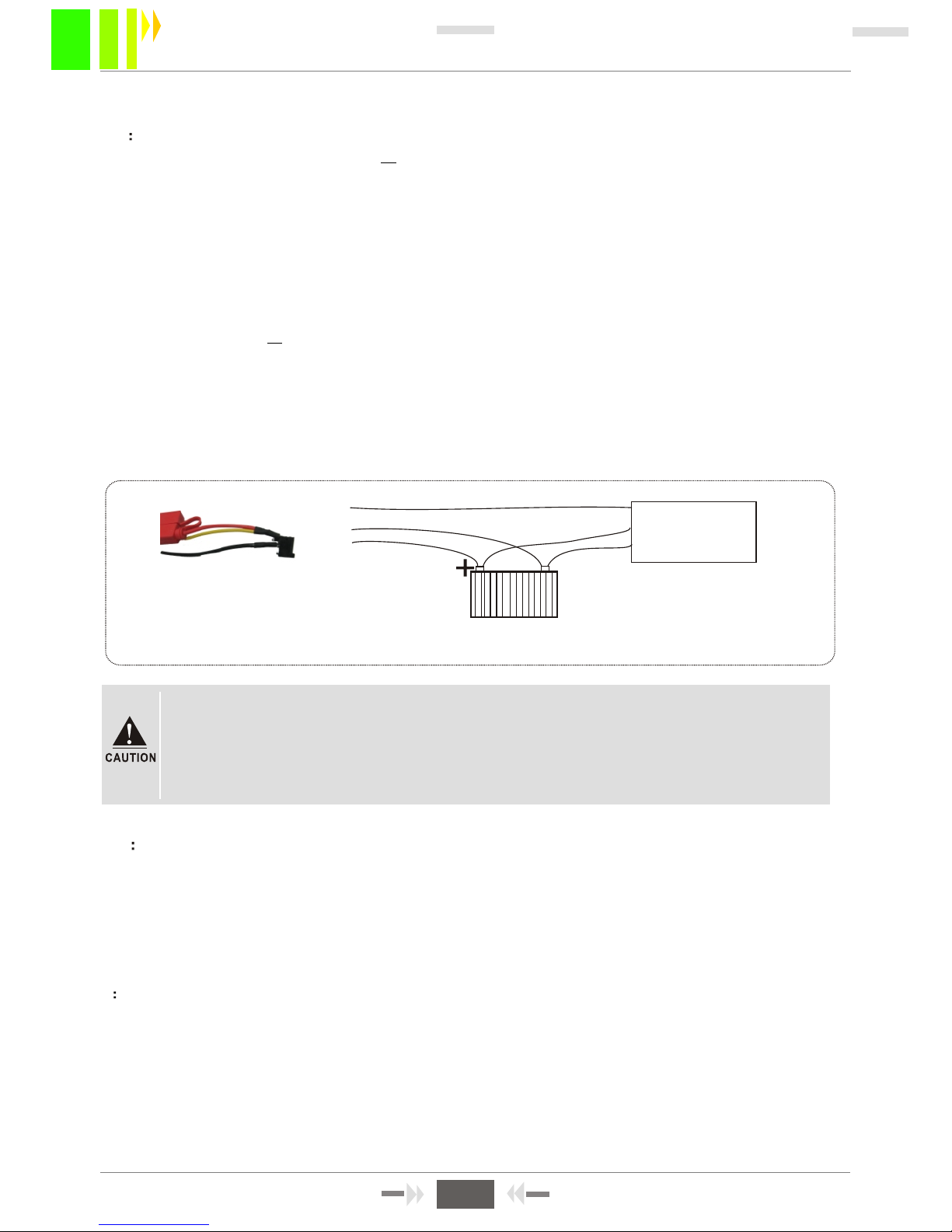
4.1 CABLES TESTING AND POWER ON
The host power cable has three wires red, black and yellow. Red and black wires connect to the car
battery directly: red wire to positive terminal and black to negative terminal. The yellow wire connects
to the ignition swich (namely the key position before start motor). However, in locations other than a
a vehicle, make the wiring connections are as follows: twist the red and yellow wires together and
connect to positive power terminal, the black wire alone to negative pole, then apply a DC12V-5A or
above switched power supply to the MDVR.
1: Connect the power cable and apply power to it. When power is provided, the blue lamp on the
panel PWR is on, and the device is in stand-by mode.
2: Connect the monitor and other relevant equipments to the MDVR via the AV-OUT cable. Verify that
all cables are connected correctly.
3: The device can be switched on only when being locked with the electronic key. Other indicator
lamps flash yellow after booting.
Figure 4-1 shows the testing cable and vehicle power cable connections.
Test cables
Vehicle control
circuit (switch)
Red cable
Black cable
Yellow cable
Vehicle Battery
-
1. The voltage range of power supply is Vdc 8-36. When only the blue lamp of the
front panel flashes, the device is in stand-by mode. After normal boot up, several
lamps will be on.
2. If power is provided through the testing cable, the MDVR can t perform a
power-off delay.
'
Figure 4-1 Vehicle wiring diagram
4.2 RECORDING SETUP
1: AUTO RECORDING
With SD card installed, the device will start recording automatically after a normal boot up of the system,
without any settings changes. DVR will operate according to the factory default settings.
NOTE: During the first use after booting into the system, format the installed SD card to ensure
that it has a compatible format.
2 TIMED RECORDING
Go to MENU - RECORD SETUP - NORMAL SETUP - REC MODE. Select Timed Record, go
to the upper menu TIMED SETUP and configure the recording time range, then save. For more
detailed menu operations, please refer to Section 3.4-3.
NOTE: Use the "+"or"-" keys (under the number"8"or"9") during the recording time range
setup.
3: ALARM RECORDING
MENU -RECORD SETUP-NORMAL SETUP--REC Mode, then change into Alarm record. Setup the
20
MDVR-50 User Manual
Page 23
alarm pre-record time (range 0-60 seconds), the alarm record delay time (range 30-900 seconds),
and the alarm output time (range 5-240 seconds). The alarm output time setting can depend on
external alarm equipment.
If installing corresponding external alarm input devices, such as an emergency switch button,
switch door magnetic door, sudden braking sensor and other sensors, the alarm settings of these
devices include several types as follows:
Level input
MDVR REAR PANEL ALARM INTERFACE
Figure 4-2
Pulse sensor
C:G-SENSOR ALARM RECORDING.
As shown in Figure 3-21, the G-SENSOR can be understood as a three-dimensional X, Y, Z coordinate
axis, which demonstrates vehicle's three status sets respectively: up and down, left and right, back and
forth. The up and down bumps, speed-up, sudden braking, side tumbling, sharp turns, etc. along
the course of vehicle can be shown on the X, Y, Z axis. The value of the threshold requires setup.
After installing the sensor in a vehicle, calibration of the X/Y/Z parameters is required; then during the
operation, measure sudden braking and
acceleration, range of value of up-and-down bumps, variation of
value for left-and-
right sharp turn, etc. to determine which axis has big changes. These operational statuses
will display and change in real time. With thresholds set and record enabled, the device will
start recording
when vehicles exceeds a threshold limit.
D: MOTION DETECTION ALARM RECORD. -TOOLS-MOTION DETECTION
As shown in Figure 3-29, turn on the enabling switch, set detection sensitivity to high, medium, or
low
according to requirements (normally set to medium). Next, set motion detection area by diagonal setup
(see Figure 3-30). By default, recording is enabled; the MDVR will trigger recording and generate alarm
record files when movement occurs in the image. (Note: All settings are in effect only after being saved.)
MENU - VEHICLE INFO - G-SENSOR
""
SYSTEM MENU
Figure 4-3
21
MDVR-50 User Manual
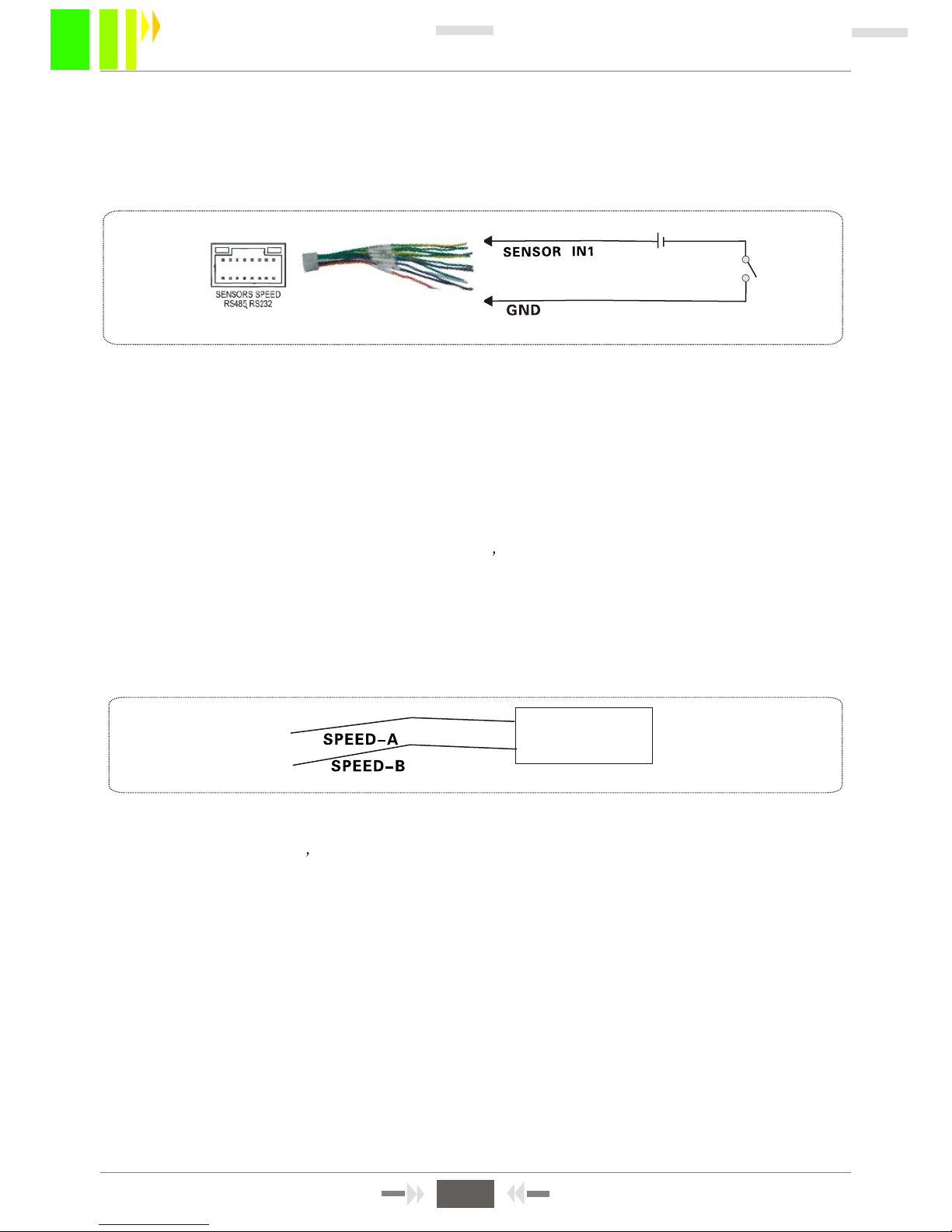
A: SENSORS INPUT ALARMS. SYSTEM MENU-VEHICLE INFO-SENSOR SETUP
In the menu shown in Figure 3-20, choose high or low trigger level, and switch on recording. This
menu corresponds to the MDVR's six external alarm input
"SENSOR IN". Connect these inputs
to the corresponding sensing switch equipments, like magnetic door, emergency
switch button,
turning lamp switch, brake pedals (shown in Figure 2-13) and etc. A basic connection diagram is
show in Figure 4-2.
B: OVERSPEED ALARM SETUP
. SYSTEM MENU-VEHICLE INFO-SPEED SET
UP
If a vehicle uses GPS to acquire speed, as shown in Figure 3-22, the GPS signal should be strong.
The threshold for an overspeed alarm should
be set to the maximum speed limit.
The switch enabling recording when vehicle when the speed exceeds the limit should generate
an alarm and trigger recording simultaneo
usly.
If a vehicle acquire speed from itself, a connection
to the speed pulse sensors is
necessary. This sensor is used to calculate
the speed ratio (the coefficient = pulse/speed). Connect
the pulse sensor to the two lines of the ve
hicle ports-SPEED-A and SPEED-B. The speed ratio is
determined using the set speed and the pulse when the course of vehicle is moving.
A simplified connection is shown as Figure
4-3.
Page 24
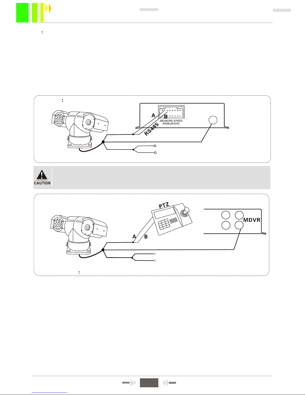
4.3 PTZ CONNECTION AND SETUPWhen When
When connecting PTZ device to set parameters, always set the correct channel
for the device. For example, if the PTZ device address is 2, set the controller to
transfer to device address 2.
Setup steps:
Step 1. Choose the PTZ protocol. Options are PELCO-D and PELCO-P.
Step 2. Set the baudrate (1200/2400/4800/9600) corresponding to the PTZ device.
Step 3. Setup the PTZ device address. This address must match the address of the PTZ device
(usually address is 1). The address of PTZ is adjustable, and must set differently for each PTZ
device on the network.
Step 4. Cable connection: the RS-485 control line on PTZ connects to the MDVR RS-485 port
(RS485-A and RS485-B).
'
TZ POWER INPUT
Video cable
MODE 1 USING TO CONTROL PTZ REMOTE CONTROL
Figure 4-4
MODE 2:USING 3-DIMENTIONAL KEYBOARD CONTROLLER TO CONTROL PTZ
3-Dimentional keyboard
Step 5. Three types of cable connections
Type 1: Connect the RS-485 control line on PTZ to the MDVR RS485-A and RS485-B ports
and video cable to the host video input port, then provide power to the PTZ device. Set the
communication parameters of the MDVR to match those of the PTZ device, and use a
remote control to control the PTZ.
Type 2: Connect the PTZ RS-485 control cable directly to a 3-dimensional keyboard controller
instead of the host MDVR, connect the video cable to the MDVR video input port, then provide
power to the PTZ and 3-Dimensional keyboard controller. Setup keyboard controller parameters
to match the PTZ device.
Type 3: Connect PTZ RS-485 control line to both 3-Dimentional keyboard controller and host MDVR
In this configuration, the PTZ device can be controlled by remote controller or keyboard controller.
'
Figure 4-5 RS485 control line connect to the keyboard controller directly
Video cable
PTZ POWER INPUT
22
MDVR-50 User Manual
Page 25
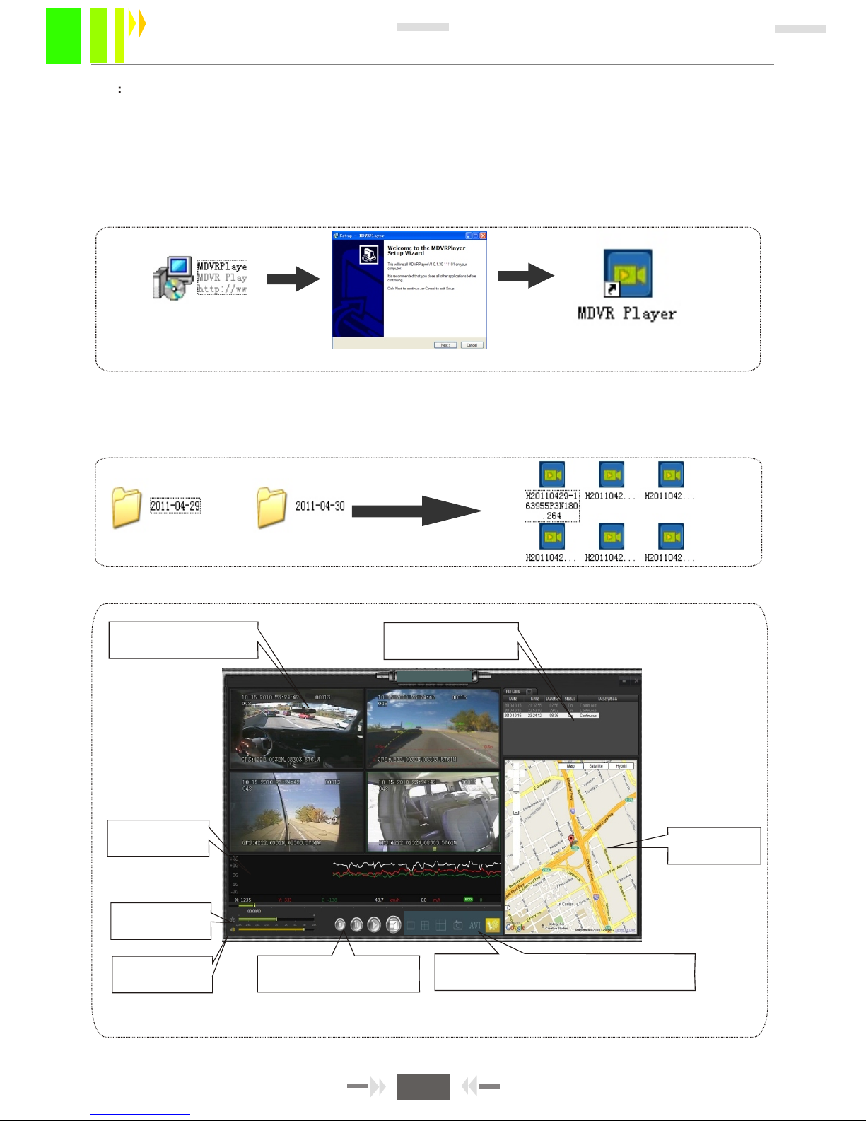
Channel playback
Figure 4-8
Play file list
G-sensor waveform
Map display
Playback
speed control
Audio on/off
Stop/play/pause/
full screen
Multi-screen, image capture, AVI
conversion, system setup
4.4 PLAYBACK RECORDED FILES ON PC
Recorded files can playback on the MDVR, or can be transferred to a PC played using the
MDVRPlayer. To install MDVRPlayer:
Double-click the CD-ROM installation files "MDVR PLayer V1.0.1.30_111221.exe", select the
installation language (Chinese and English), click OK, then click NEXT. When the
installation is complete, an icon for the player is on the desktop. See Figure 4-6.
Figure 4-6
Remove the SD card from the MDVR, then insert it into PC SD card reader.
After the PC recognizes the SD card, open the "File list" folder, then open the folder where
recorded files are stored. Folders are named by date and files are named by date and time.
See Figure 4-7. A playback screen is shown in Figure 4-8.
Figure 4-7
23
MDVR-50 User Manual
Page 26

Q: What should I do if a problem occurs that I can not solve myself?
A: Please write down the unit number, software version number, and describe the problem in
detail. Then submit it to our technical support for analysis. The more detailed the
description that you include will make our analysis more efficient.
Q: There's no video output from the Mobile DVR.
A: 1. Check whether the host is on. If only one blue lamp is on, the host is in standby mode.
Also check whether the red and yellow lines of the MDVR power cable have voltage.
If only one line has voltage, the device will not boot.
2. Check if the monitor is powered on and its video is switched to AV status.
3. Check if the AV-OUT cable is connected properly to the monitor .
4. Check whether the host is locked properly. If not, it cannot boot normally.
Q: What if the MDVR video input port and the camera AV-OUT port connectors don't match?
A: The MDVR uses 4PIN port or Aviation port. Cameras use 4PIN/BNC port. If they do not
match, use an adapter to connect them.
Q: An SD card was inserted, but the device can not record after booting.
A: 1. Verify that the SD card is not locked. Also check loose contacts in the SD card slot.
2. If it is a new SD card used for the first time, format the card using the procedure above.
3. Check whether the recording channel is switched off. If timing record is set, the device will not
record if it is not during the recording time.
4. Check whether the SD card is removed with power on. Remove the SD card only when
the device is off.
Q: Recorded files are missing or there are no files recorded during a certain time.
A: 1. Check the last file recorded before and first file recorded after the missing files.
2. Check if the MDVR was not switched on during that period. For example, the host does not set delay
record when the driver stops the vehicle half-way or loads and uploads cargo.
Q: Why is the PTZ device out of control and cannot pan or tilt?
A: Verify that the protocol, baudrate and device address are set correctly. Verify that the channel
is selected to maximum screen when controlling the PTZ. For example, when controlling the
second channel, its image should be maximized to full screen.
APPENDIX 1: FAQ
24
MDVR-50 User Manual
FAQ ABOUT GPS
Q: GPS module exists but without coordinate information?
A: 1.Verify that the GPS module is installed properly.
2. Check the GPS antenna. Make sure it is not broken. Test the MDVR in a location where the
signal is strong. Note that GPS signal may be blocked by car glass.
3. Place the GPS antenna outdoor. If tested indoor, GPS signal may be blocked.
Q: The GPS location shows deviations on the map?
A: Signals are valid if GPS module has positioned. The deviation can be caused by many reasons,
such as a government restrictions, allowable error, GPS signal interruption, etc. The actual satellite
map has deviations for safety reasons, and they can be corrected by GPS calibration.
Page 27
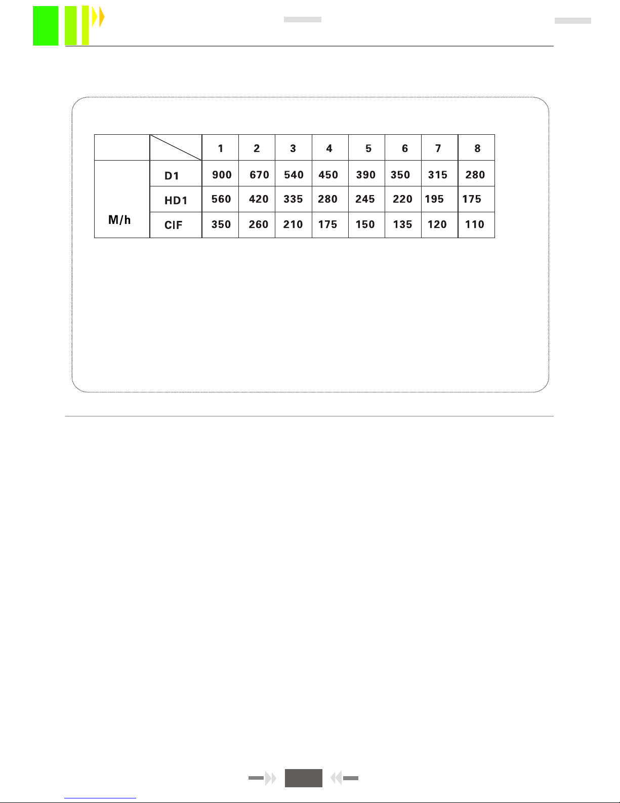
APPENDIX 2: STORAGE SPACE REQUIREMENTS
Quality
Resolution
Storage
Space
Correlation between image quality and recording space
The storage space required by one channel for each hour of recording
is shown in the table above. The actual recording file size is dependent
on the current channel, illumination variant, object movement, etc.
If the image is always still, the recording file will be smaller. To save
space, turn off audio recording and turn off the channel without video.
25
MDVR-50 User Manual
 Loading...