

Page 1
(4) (5)
(1) (2) (3)
Supercircuits, Inc.
MDVR33COV
0HJDSL[HO&RYHUWDigital Camera
Quick Guide
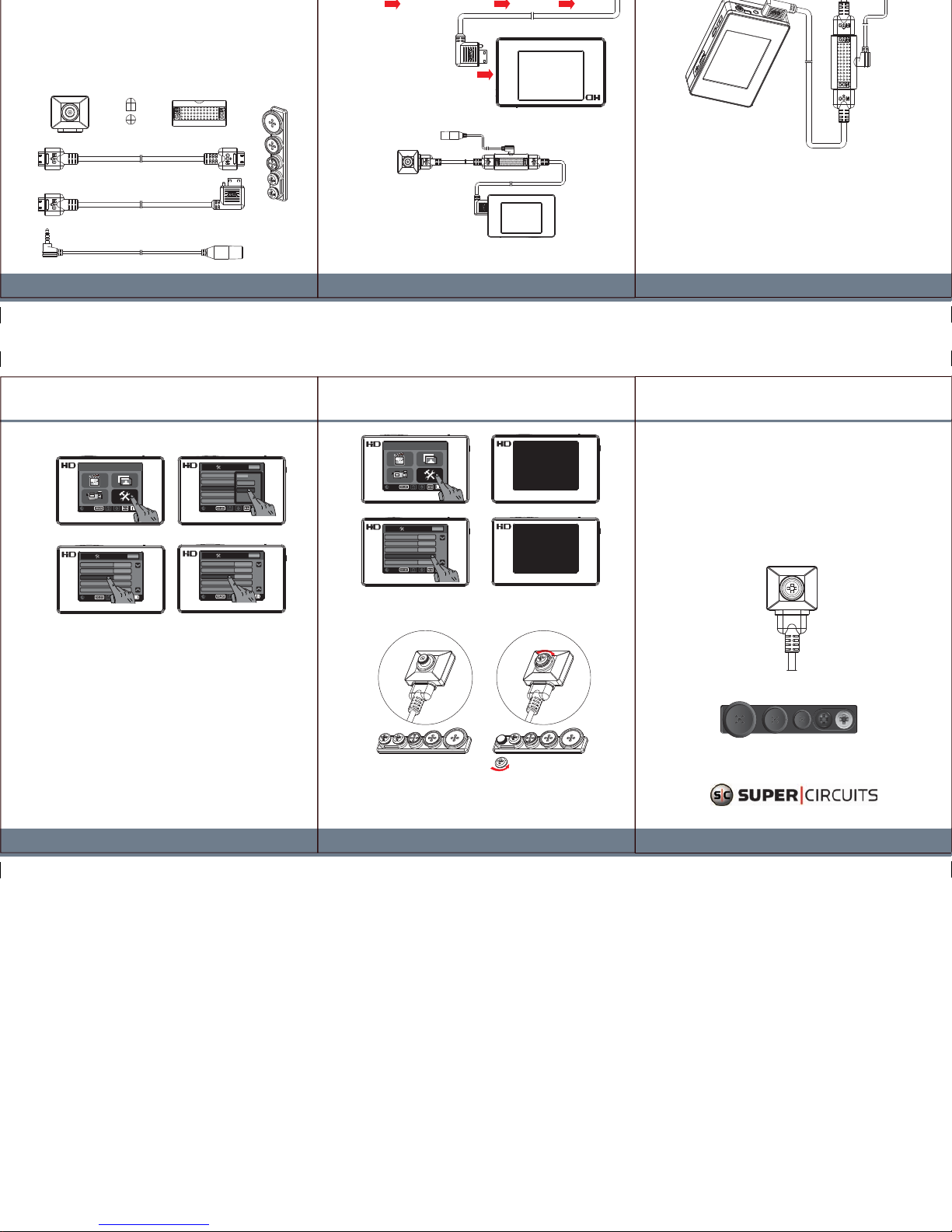
5. Setting Video Signal System
6. Camera Calibration
MAIN MENU
SD
STORAGE
SD
STORAGE
PAGE
0001/0009
Settings
ESC
ESC
SD
STORAGE
PAGE
0001/0009
Settings
ESC
ESC
ESC
ESC
NEST
PAL
Digital CMOS Setting
Digital CMOS Setting
PAL
SD
STORAGE
PAGE
0001/0009
Settings
ESC
ESC
Digital CMOS Setting PAL
(1)
(3)
(2) (4)
1. Press “Setting” on the Main Menu.
2. Drag the Setting Menu down to select “Digital CMOS Setting”.
3. Select either PAL or NTSC based on your country’s
video signal system.
4. After making your selection, press “Digital CMOS Setting” again to
complete the setting.
1. Press “Setting” on the Main Menu.
2. Drag the Setting Menu down to select “Digital CMOS Calibration”.
3. After making your selection, “Calibrating” will appear on the screen.
4. When calibration is complete, “Cable Disconnect” will appear on the screen.
5. Unplug the cable to complete calibration.
SD
STORAGE
PAGE
0001/0009
Settings
ESC
ESC
Digital CMOS Setting PAL
SD
STORAGE
PAGE
0001/0009
Settings
ESC
ESC
ESC
ESC
NEST
PAL
Digital CMOS Setting
7. Change Covert Lens Cap
SD
STORAGE
PAGE
0001/0009
Settings
ESC
ESC
Digital CMOS Calibration
PAGE
0001/0009
Settings
Calibrating
Cable Disconnect
MAIN MENU
SD
STORAGE
(1)
(3)
(2) (4)
1. Remove the lens cap from the camera, and the desired lens cap from the set,
by unscrewing them (rotate counterclockwise).
2. Place the desired lens cap onto the camera.
3. Screw the desired lens cap onto the camera (rotate clockwise) until it is secure.
V1.0
2. Package Content
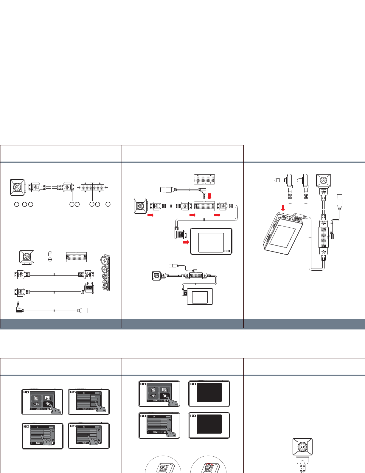
1. Name and Parts
3. Camera Setup Illustration
WDR Digital Camera Lens Cap Image Refine Connector
Camera to Connector Cable
Connector to DVR Cable
Extension Microphone
1 2 3 4 5
6 7 8
1. Camera Lens 5. HDMI Socket of Connector
2. HDMI Socket of Camera 6. Extension Mic Socket
3. HDMI Jack of Cable 7. Built-in Microphone
4. HDMI Jack of Cable 8. HDMI Socket of Connector
Back View of
Image Refine
Connector
1. Connect camera to connector
using required cable.
2. Plug-in extension microphone
to proper socket of the connector.
3. Connect connector to portable DVR
using required cable.
Note: It is required to calibrate camera
and configure video signal system
after connection of all parts is established.
Microphone
Camera Connector
Portable DVR
Extension Microphone
Connection of all Components
4. Lens Cap On
1. Collect the black lens cap from the screw pack.
2. Place on top of the camera lens.
3. Press “Power” button to turn power of PV-500EVO on.
4. Then follow the steps described on next page to start
camera calibration.
Covert Lens
Cap
80x120mm
80x120mm
Page 2
(1) (2) (3)
CMD-BU13
HD CMOS WDR Digital Camera
Quick Guide
5. Setting Video Signal System
MAIN MENU
SD
STORAGE
SD
STORAGE
PAGE
0001/0009
Settings
ESC
ESC
SD
STORAGE
PAGE
0001/0009
Settings
ESC
ESC
ESC
ESC
NEST
PAL
Digital CMOS Setting
Digital CMOS Setting
PAL
SD
STORAGE
PAGE
0001/0009
Settings
ESC
ESC
Digital CMOS Setting PAL
(1)
(3)
(2) (4)
1. Press selection “Setting” from Main Menu.
2. Drag the Setting Menu down to select “Digital CMOS Setting”.
3. Make the selection either PAL or NTSC based on user country’s
video signal system.
SD
STORAGE
PAGE
0001/0009
Settings
ESC
ESC
Digital CMOS Setting PAL
SD
STORAGE
PAGE
0001/0009
Settings
ESC
ESC
ESC
ESC
NEST
PAL
Digital CMOS Setting
7. Interchange Covert Lens Cap
SD
STORAGE
PAGE
0001/0009
Settings
ESC
ESC
Digital CMOS Calibration
PAGE
0001/0009
Settings
Calibrating
Cable Disconnect
MAIN MENU
SD
STORAGE
(1)
(3)
(2) (4)
2. Package Content
1. Parts
3. Camera Setup Illustration
WDR Digital Camera Lens Cap Image Refine Connector
Camera to Connector Cable
Connector to DVR Cable
Extension Microphone
1 2 3 4 5
6 7 8
1. Camera Lens 5. HDMI Socket of Connector
2. HDMI Socket of Camera 6. Extension Mic Socket
3. HDMI Jack of Cable 7. Built-in Microphone (optional)
4. HDMI Jack of Cable 8. HDMI Socket of Connector
Back View of
Image Refine
Connector
1. Connect camera to Connector
using the required cable.
2. Plug the extension microphone
into Connector mic socket.
3. Connect Connector to portable
DVR using required cable.
Note: Calibrate camera
and configure video signal system
after interconnecting all components.
Microphone
Camera Connector
Portable DVR
Extension Microphone
Connection of all Components
4. Lens Cap On
1. Remove the black lens cap from the screw pack.
2. Place the cao on the camera lens.
3. Press the DVR “Power” button to turn it on.
4. Follow the steps on next page to
calibrate the camera.
Covert Lens
Cap
80x120mm
80x120mm
(optional)
(optional)
(optional)
(optional)
(optional)
 Loading...