

Page 1
DVR-30
Mobile Vehicle Video Recorder
Page 2
1
SAFETY PRECAUTIONS
All the following safety and operation instructions which will prevent harm or damage to the operator or
other persons should be read before the unit is operated.
INFORMATION
This equipment has been tested and found to comply with the limits for a Class A digital device,
pursuant to Part 15 of the FCC Rules. These limits are designed to provide reasonable protection
against harmful interference when the equipment is operated in a commercial environment. This
equipment generates, uses, and can radiate radio frequency energy and, if not installed and used
in accordance with the instruction manual, may cause harmful interference to radio
communications.
Operation of this equipment in a residential area is likely to cause harmful interference in which
case the user will be required to correct the interference at his own expense.
WARNING
!
To reduce the risk of fire or electric shock, do not expose this appliance to rain or moisture.
!
Do not block ventilation openings.
!
Do not place anything on top of the unit that might spill or fall into it.
!
Do not attempt to service this unit yourself as opening or removing covers may expose you
to dangerous voltage or other hazards. Please refer all servicing to qualified service
personnel.
!
Do not use liquid cleaners or aerosols for cleaning.
!
This installation should be made by a qualified service person and should conform to all local
codes.
To prevent fire or electric shock, do not overload wall outlets or extension cords.
This unit must be grounded to reduce the risk of electric shock hazard.
CAUTION
!
Danger of explosion if battery( RTC Battery ) is incorrectly replaced. Replace only with the
same or equivalent type recommended by the manufacturer. Dispose of used batteries
according to the manufacturer’s instructions.
!
Risk of explosion if replaced by an incorrect type. Dispose of used batteries according to
the instructions.
Page 3

2
1. INTRODUCTION ................................. 3
1.1 YOUR DRIVING HELPMATE .................3
1.2 Product Introduction................................4
1.3 Product Features ....................................5
1.4 ACCESSORIES......................................6
1.5 FRONT / REAR VIEW ............................7
1.5.1 Front View..............................................7
1.5.2 Rear View...............................................9
1.5.3 Inner Host Rear View...........................10
1.5.4 GPS Connector....................................10
1.5.5 Camera In Connector...........................11
1.5.6 Power Delay Connection .....................11
1.5.7 Power Connector.................................12
1.6 I/O Port......................................................
..................................................................
13
1.7 I/O Connection......................................14
1.8 Voltage Management............................15
2. INSTALLATION................................. 16
2.1 Basic Connection..................................16
2.2 Hard-disk Drive Installation...................18
2.3 System Information and........................19
Channel Selection.......................................19
2.3.1 System information..........................19
2.3.2 Channel Selection................................19
2.4 Updating System Software ...................20
3. OPERATIONS ................................... 21
3.1 Configuring Recording Settings............21
3.2 Recording Operations...........................23
3.2.1 Manual Recording............................23
3.2.2 Alarm Recording...............................23
3.2.3 Externally Triggered Recording......23
3.3 Playback Operations......................24
3.3.1 Normal Playback..............................24
3.3.2 Fast Forward/Backward..................24
3.3.3 Slow Forward/Reverse....................24
3.3.4 Play back picture-by-picture...........25
3.4 Search Operations............................... 25
3.4.1 FULL LIST Search........................... 25
3.4.2 ALARM LIST Search....................... 25
3.4.3 TIME Search .................................... 26
3.4.4 THUMBNAIL Search....................... 26
3.4.5 The SD CARD Search.................... 27
3.5 Backup Operations............................... 28
3.5.1 SD Card Backup Operations......... 28
3.6 The Key Lock Operation ...................... 29
4. MENU SETUP.................................... 30
4.1 REC Setting .............................................
.................................................................
30
4.2 The ALARM Setting ............................. 32
4.3 The CLOCK/ TITLE Setting.................. 33
4.4 The COMMUNICATION Setting........... 34
4.5 DISK Setting......................................... 34
4.6 The SYSTEM Setting........................... 35
6. OTHER...............................................37
5.1 The RS-232 Setup & Protocol.............. 37
5.1.1 The RS-232 Protocol........................... 37
5.1.2 The Communication Protocol.............. 37
5.2 System Default..................................... 40
5.3 O.S.D Message .................................... 41
5.4 Time Index Table ................................. 42
5.5 Specifications....................................... 43
APPENDIX 1. –Virtual Serial Port.............. 44
1. Connection Application Software
Installation....................................................
44
2. The PaPaGo Electronic Mapping Setting. 48
3. The HDD Viewer Setup............................ 49
4. The Working Screen................................. 50
APPENDIX 2. – FAQ.................................. 51
APPENDIX 3. – Changing the built-in hard
disk of the mobile DVR............................
52
APPENDIX 4. – Vehicle Cameras.............. 55
CONTENTS
Page 4

3
1. INTRODUCTION
1.1 YOUR DRIVING HELPMATE
1. Reliable real time recording of vehicle interiors as well as surrounding road
environments.
2. Portable inner host, easy to extract and carry wherever and whenever you like as
well as install in any outer casing.
3. Records the information from the GPS and uses the eMap software to show the
exact route of your vehicle at any given time.
4. Provides clearer and more accurate video records.
5. Easy to connect to a PC via a USB interface after the inner host has been taken
out of its outer casing.
6. Captures all your vehicle-related information from the data box in your video
records. This will prove to be invaluable evidence in case of any road incident or
accident.
1. INTRODUCTION
Page 5

4
1.2 Product Introduction
The DVR-30 is an advanced vehicle video recorder. It can simultaneously display real-time images from
four cameras along with information data through the mobile video recorder directly onto your monitor. The
mobile DVR has four video channels which you can access either in the quad mode or singl e cha nnel.
We use a hard disk device in this mobile recorder to store your images over a longer time. The recording
device has further already been tested for shock-proof and extreme temperature-proof durability in rugged
environments, with ventilation holes provided to lower the internal temperature for cooling.
The special design of the DVR enables you to easily retrieve the recording hosts inside, which are handy and
portable enough to carry anywhere you want and link up with PCs and TV monitors for direct display.
The DVR-30 includes the Global Position System (GPS) which helps disclose a vehicle's location
information -- the GPS information can also be displayed by eMap Software to know about a car's exact
route. The DVR can also be connected to the car's information Black Box to access a vehicle's driving
speed , engine RPM, wheel turns, driving time periods, braking, signal lights, and so on, all of which data is
received and saved by the DVR. While searching for information, any important image you may want to save
can be stored via an SD card.
This mobile recorder provides all the above practical and useful features you can expect of it. It's your best
choice out of the entire range of mobile video recorders available. This multi-functional mobile video
surveillance product protects the safety of both the driver and the passengers.
INTRODUCTION
( continued )
Page 6

5
1.3 Product Features
Quad-based operation: real-time operation and playback (30 FPS/ per channel).
M-JPEG compression with resolution up to 720X480 (NTSC) / 720X576 (PAL).
4x 6-pin Din connectors for AV inputs.
4 camera audio inputs, 2 auxiliary audio inputs, 1 audio output.
The HDD's video records can be plugged in and played back on a TV directly.
Pre-alarm image recording.
USB interface showing video records in a PC.
1 fixed 2.5" IDE HDD as storage medium for extended continuous digital recording.
Supports GPS (RS-232).
GPIO: 4 inputs and 2 outputs.
Operation power: DC 11~14.5 V.
Operation temperature: Standard HDD: 0 – 45℃ (32 –113℉)
Industrial HDD: 0 – 60℃ (32 –140℉)
Dimensions: 178 x 173 x 50 mm.
Time-lapse and real-time recording.
Refresh rate up to 30 IPS (25 IPS for PAL).
Image quality selectable at 4 different levels for recording.
Alarm recording mode.
Quick search by time, alarm, event, and recording list.
Fast and slow playback of recorded video at various speeds.
Single-picture playback.
On-screen setup menu, title and system timer.
Password protection.
Disk-full warning and operation status LEDs.
RS-232 communication port.
Remote controller.
Operation-status record log.
Automatic detection of the current voltage.
Audio function included.
Built-in SD card slot for copying images to an SD card.
Watermark.
Window Division.
Vibration and mechanical
shock protection.
Page 7
6
1.4 ACCESSORIES
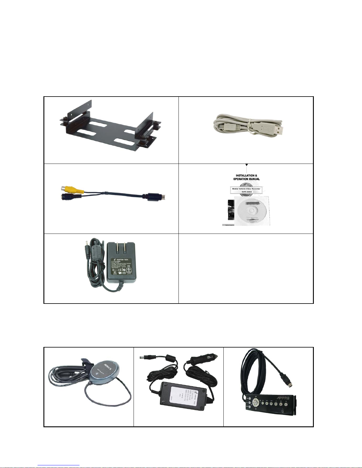
The device package contains the following items:
Shockproof unit x 1.
Mini USB cable x 1.
Mini Din Splitter x 4– connects all kinds of professional CCTV cameras.
User Manual and CD x 1.
Adapter 5V x 1.
Shockproof unit x 1 Mini USB cable x 1
Mini Din Splitter x 4 User Manual and CD x 1
Adapter 5V x 1
The optional accessories contain the following items:
GPS GR213 (optional).
Mobile Power Adapter MADS12.6D3.5B (optional).
RC-5013 (optional).
GPS GR213 (optional) MADS12.6D3.5B (optional) RC-5013 (optional)
Page 8
7
1.5 FRONT / REAR VIEW
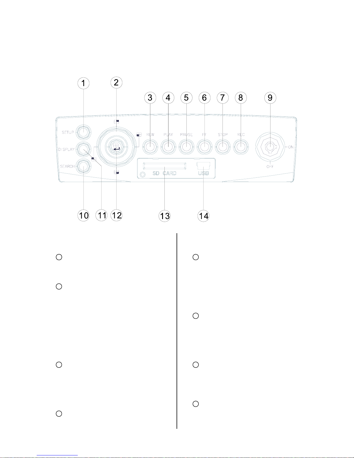
1.5.1 Front View
1
SETUP button:
Press this to enter the setup menu. Press
again to exit the setup mode.
2
Left/ Right/ Up/ Down (CH1/ CH2/
CH4/ CH3) buttons:
In the menu setup mode / search mode,
press the four buttons on the dial to
highlight desired items in the menu
setup mode. In the live / play mode,
press the four buttons on the dial to
select a channel for display.
3
REW button:
Press this to play a recorded video in
the reverse direction at a speed that's
faster or slower than the recorded speed
in the play mode.
4
PLAY button:
Press to play back a recorded video
from the hard disk. (A lig ht glows green
in the PLAY mode.)
5
PAUS E button:
In a playback display, press this to
freeze the display. During the freeze,
press to display one frame of a picture
at a time in the forward direction (A lig ht
glows red in the PAUSE mode.)
6
FF button:
Press this to play a recorded video in
the forward direction at a speed that's
faster or slower than the recorded speed
in the play mode
7
STOP button:
Press to stop playing back a recorded
video. (A light glows red in the STOP
mode.)
8
REC button:
Push to start recording video into a hard
disk while in the live display mode. (A light
Page 9

8
glows red in the REC mode.)
9
Inner-case lock:
This key lock secures the inner case
with the hard disk in place. When you
lock it in, it powers on the device. When
you unlock this key and take out the
inner case, the power turns off
automatically.
10
SEARCH button:
Press to enter the search mode to
access the recorded video.
11
DISPLAY button:
Press to show the system operation
status on the screen.
12
Enter / (Quad) button:
Press to enter a selected item and save
the setting in the menu setup mode. In
the live/ play mode, use this button to
show a quad display.
13
SD CARD slot:
This is used for system software
updating and archiving/ accessing of
critical images.
14
USB port:
This is used for system picture playing.
Use this port to connect with your PC or
notebook. You can easily and quickly
capture data from a hard disk in the
vehicle DVR.
Page 10
9
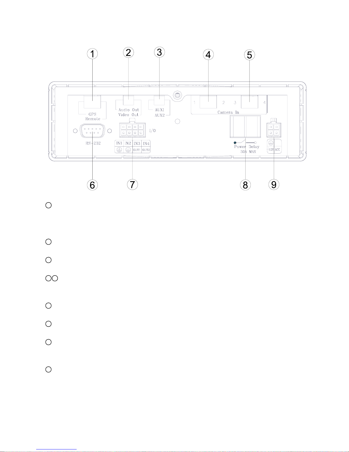
1.5.2 Rear View
1
GPS & Remote Controller Connector:
The left side connector links up with the GPS receiver to capture local position information data.
Please refer to the section 1.5.4 GPS CONNECTOR. The right side connector links up with the
remote controller
2
Audio Out / Video Out:
Your LCD monitor or other monitor can signal here.
3
AUX 1 / AUX 2:
Use this if you have external audio sources.
4 5
Camera In connector:
There are four connectors here to connect the Video / Audio In from a camera. Please refer to the
section 1.5.5 CAMERA IN CONNECTOR.
6
RS 232 port:
This communication port functions as a connector to an external device, for example a data box.
7
I / O port:
This connector links up with an external device.
8
Power Delay:
This connector will avoid the vehicle device getting excess power. Please refer to section 1.5.6
POWER DELAY CONNECTION.
9
Power Input:
This connector links up with the power from the vehicle (12V). Please refer to section 1.5.7 POWER
CONNECTOR.
Page 11

10
1.5.3 Inner Host Rear View
1
Plug Inlet:
The inlet connects to an external power supply. Connect to 5V DC UL Listed Class 2 Power Supply.
2
Hard Metric Connector (Male):
This connector links up with the outer casing.
3
Audio Connector:
Connect here to hear the audio's sound when you play the inner host case outside the outer case.
4
Video Connector:
Connect here to play the video when you play the inner host case outside the outer case.
1.5.4 GPS Connector
(PS/2 composition of male connector)
PIN NO.
PIN Assignment
1.
+ 5V DC
2.
Not Connected
3.
RX
4.
Ground
5.
TX
6.
Not Connected
Page 12
11
1.5.5 Camera In Connector
(PS/2 composition of female connector)
PIN NO. PIN Assignment
1.
Audio In
2.
Not Connected (Mirror)
3.
+ 12V DC
4.
Video In
5.
Ground
6.
Ground
Note: The maximum electric current provided for 4 mobile cameras is 1 ampere ( 1A ) in total.
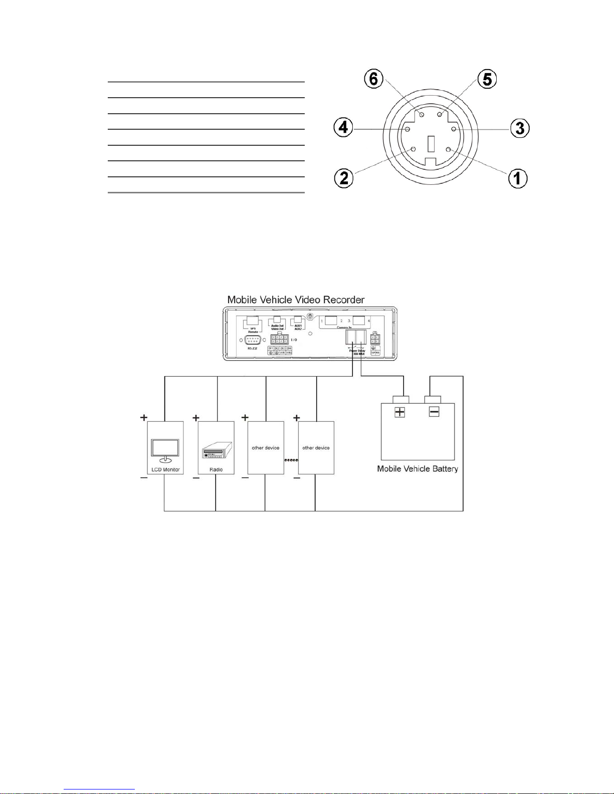
1.5.6 Power Delay Connection
The diagram here illustrates the power delay connection structure. If a device needs to work with our
DVR, it needs to start operating after our DVR has begun operating. See the diagram below to help
you with the mobile vehicle video recorder's power delay connector on its rear panel.
Enter the mobile vehicle DVR's "MAIN MENU" page and choose the third item, "CLOCK / TITLE". Now
enter the "CLOCK / TITLE" page, and you will see two items, "DELAY ON" and "DELAY OFF". For both
these items, the default setting is "OFF". You can set the delay time of the relay by choosing one of the
following options.
DELAY ON: This entry sets the delay time of the function activation of the relay connector after the DVR
powers up.
DELAY OFF: This entry sets the delay time of the function activation of the relay connector after the ACC is
powered off. The relay connector will function as per the delay time you set by your chosen
option. After the relay connector's delay time duration is over, the relay connector will
automatically turn off, followed by the DVR. (The DVR which is connect with a cigar-lighter of a
vehicle for power supply will stop working when turning off the ignition.)
Note: The relay connector’s electric current range goes to a maximum of 30 amperes.
Note: Our "POST REC DURATION" function also sets the time as per any of the six options available, af ter
the ACC has been turned off. Please always be mindful of the fact that, if the time duration set for
either "DELAY OFF" or "POST REC DURATION" is longer than the other one, the DVR will wait for
the longer setting to end before shutting down.
Page 13
12
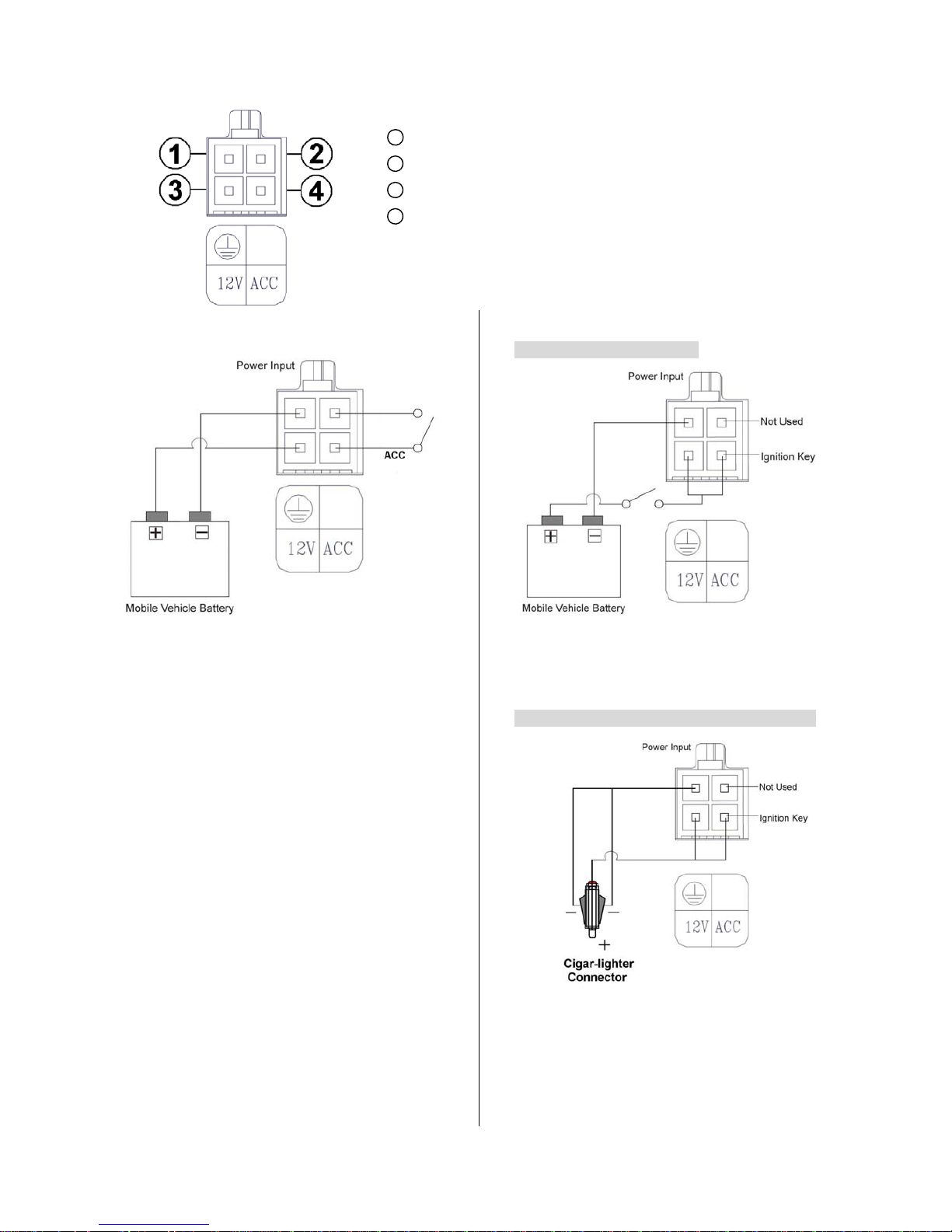
1.5.7 Power Connector
1
GND: Ground contact.
2
Not used.
3
12 V: This pin is connected to the vehicle battery.
4
ACC: This pin is linked to the vehicle ignition key to start the
DVR.
Pin connections with the ignition key
In the above diagram, pin 1 is connected to the
vehicle battery minus, pin 3 to the battery plus,
and pin 4 to the vehicle ignition key.
Pin connections without the ignition key
I. Connect with the Battery
In the above diagram, pin 1 is connected to the
vehicle battery minus, and pins 3 and 4 are
connected together to the vehicle battery plus.
II. Connect with the Cigar-lighter Connector
In the above diagram, pin 1 is connected to the
Cigar-lighter Connector minus, and pins 3 and 4
are connected together to the Cigar-lighter
Connector plus.
Note: If the mobile vehicle battery is over 16.1 volts or under 10.4 volts, the DVR will not work.
Page 14
13
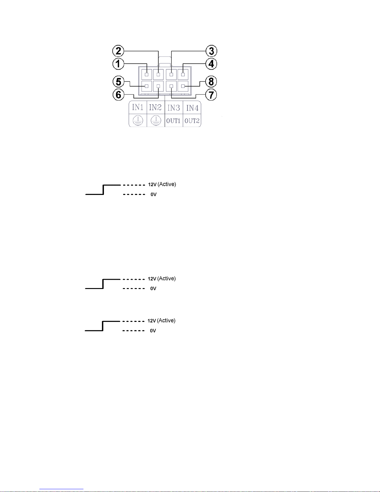
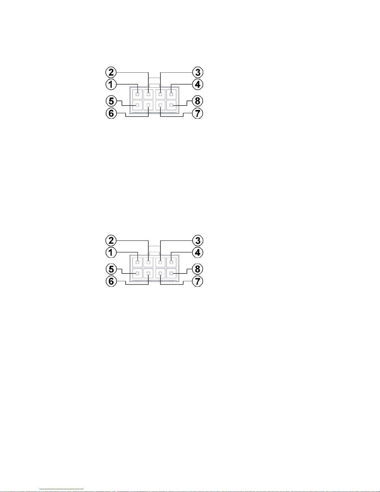
1.6 I/O Port
This figure is seen from the rear view.
1. I/O IN1 (INPUT): This is an alarm input which can be programmed in the menu system to Normally
Open or Normally Closed.
2. I/O IN2 (INPUT): same as above.
3. I/O IN3 (INPUT): same as above.
4. I/O IN4 (INPUT): same as above.
5. GND: Ground Contact.
6. GND: Ground Contact.
7. I/O OUT1 (OUTPUT): This is an alarm output trigger. Connect this to external devices such as
buzzers or lights.
8. I/O OUT2 (OUTPUT): This is an alarm output trigger. Connect this to external devices such as
buzzers or lights.
Page 15
14
1.7 I/O Connection
ALARM:
In the "MAIN MENU" page, click "ALARM" to enter the "ALARM" page. In this page, go to the "I/O
CONNECTION" item which has two options, "ALARM" and "VEHICLE SIGNAL". If you choose "ALARM", the
I/O port will change its meanings:
pins 1, 2 and 3 will become an alarm input which can connect with three different sensors and receive a
trigger; pin 4 can receive the "Reset" trigger; pins 5 and 6 are ground contacts; pin 7 can send out an alarm
output trigger from pins 1, 2 and 3, and connect to external devices like buzzers or lights; and pin 8 is N/A
(not applicable).
VEHICLE SIGNAL:
In the "MAIN MENU" page, click "ALARM" to enter the "ALARM" page. In this page, go to the "I/O
CONNECTION" which has two options, "ALARM" and "VEHICLE SIGNAL". If you choose "VEHICLE
SIGNAL", the I/O port will change its meanings:
pin 1 will connect with the leftside car signal light and receive the trigger signals; pin 2 will connect with the
rightside car signal light and receive the trigger signals; pin 3 is N/A (not applicable); pin 4 can connect with
the car stopping signal light to receive the brake triggering signals; pins 5 and 6 are ground contacts; pin 7
and 8 are N/A (not applicable).
Page 16
15
1.8 Voltage Management
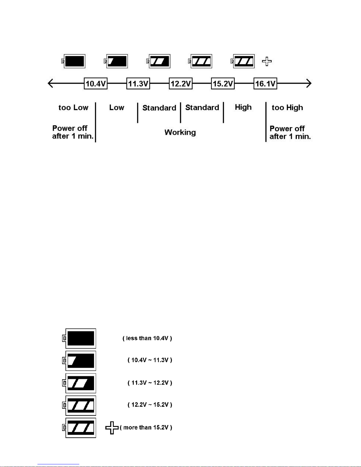
You can display the system - setting information after you press the "DISPLAY" button on the front panel. On
this screen you can see the battery voltage icons. Please consult the above diagram to know the battery
voltage status.
Between 10.4 volts and 16.1 volts, the battery is in the "Working" mode.
Between 11.3 volts and 15.2 volts, the battery is in the "Standard" mode.
Between 10.4 volts and 11.3 volts, the battery is in the "Low" mode.
Between 15.2 volts and 16.1 volts, the battery is in the "High" mode.
If the voltage is less than 10.4 volts, the battery is in the "Too low" mode", and the DVR will automatically
power off after 1 minute of beeping.
If the voltage is more than 16.1 volts, the battery is in the "Too high" mode, and the DVR will automatically
power off after 1 minute of beeping.
Note: 1. After the car motor is switched on ( ACC-On ) for 3 minutes, even if the voltage is too high or too low,
the DVR won't shut down, only beep.
2. When the car motor is switched off ( ACC-Off ), the DVR will power off, too, after 1 minute of beeping.
Page 17
16
2. INSTALLATION
2.1 Basic Connection
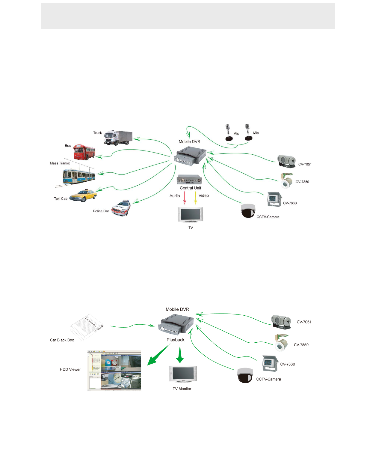
Mobile Video Surveillance Solution
This is the mobile DVR, our video surveillance device for durable use in the vehicle. It's a
multipurpose, multi-source, multi-media device for monitoring your vehicle, pinpointing its
route and location, and recording and playing vital incidents related to it, in the interests of
vehicle security and welfare.
The mobile DVR provides advanced text insertion technology that is compatible with
mobile black boxes which record all the relevant details of driving. For example, all
information regarding the driving speed, engine RPM, wheel turning angles, driving time
periods, brakings, signal lights, and the GPS position can be retrieved from the black box
system. The data can be stored, recorded and transferred to a computer or to the mobile
DVR directly for data storage and retrieval to ensure a car fleet’s and/ or individual driver’s
quality performance.
The mobile DVR is compatible with the stand-alone GPS receiver, and it can also
configure and record a driver’s location (latitude and longitude) with video data. Besides, it
can playback video by our HDD viewer software, which can track a driven route using all
GIS/e-Map software.
2. INSTALLATION
Page 18
17
Additionally, the mobile DVR has eight GPIO PINs connecting it with your car's external
signals, such as brakings or signal lights. As an example, when the vehicle's driver
operates a single light, the rear camera will start to work and record all the objects and
events behind the vehicle.
The DVR is also linked by Din connectors to four cameras recording all events and scenes
around the vehicle, and also to two auxiliary audio recorders for stereo recording of
sounds of the vehicle and its surroundings. These provide a complete record of all critical
incidents relating to your vehicle.
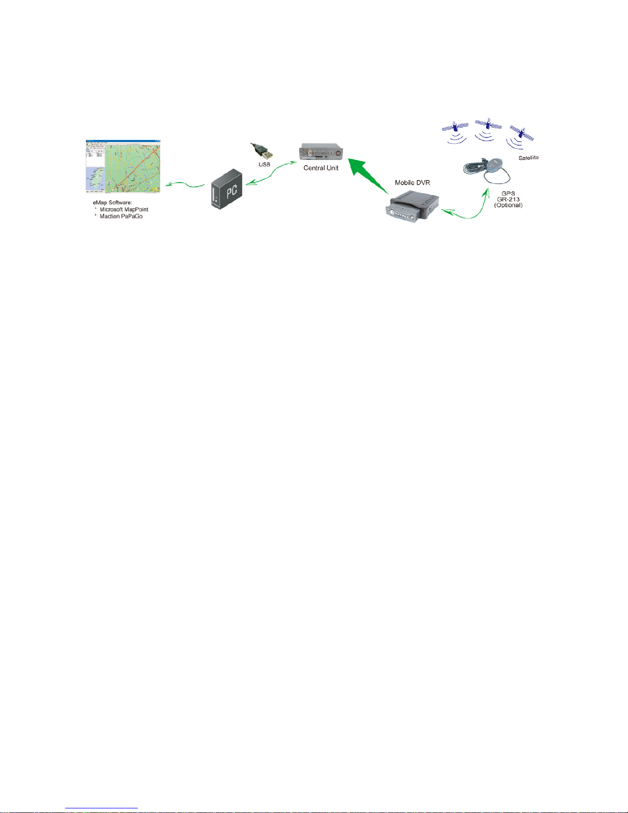
Inside the outer case of the DVR is the inner, recording host. You can take out this light,
portable host whenever you like and take it with you wherever you want. To play its
recorded contents you can connect it to a PC and use the hard disk drive viewer software
to play back the video information. In addition you can use a USB interface to connect the
DVR to the PC and use eMap software to map the exact route your vehicle has taken. The
inner host can also be linked by video and audio outputs to a monitor to play back its
records. Finally, you can insert an SD card into the SD card slot in the host's front panel to
record video clips of the most vital images and sections of the recordings you want.
Page 19

18
2.2 Hard-disk Drive Installation
The DVR is equipped with a compartment of
a hard disk drive. The unit usually comes with
one hard-disk drive installed in compartment
HD1, which is default- configured as a master.
The jumper-settings arrangement of installed
hard-disk drive for the system (Table 2.2 A.) is
shown in the tables below.
Table 2.2 A. The jumper settings of hard
disk drive in the system
Location Jumper
IDE 1 Compartment HD 1 Master
Table 2.2 B. Compatible hard-disk drives
Manufacturer Model Capacity Rotation Size
WD400VE 40GB IDE 5400 RPM
2.5"
WD600VE 60GB IDE 5400 RPM
2.5"
WD800VE 80GB IDE 5400 RPM
2.5"
WD1000VE 100GB IDE 5400 RPM
2.5"
Western Digital
WD1200VE 120GB IDE 5400 RPM
2.5"
ST93811A 30GB IDE 5400 RPM
2.5"
ST94813A 40GB IDE 5400 RPM
2.5"
ST98823A 80GB IDE 5400 RPM
2.5"
ST9100824A 100GB IDE 5400 RPM
2.5"
ST9120821A 120GB IDE 5400 RPM
2.5"
ST920813AM 20GB IDE 5400 RPM
2.5"
Seagate
ST940813AM 40GB IDE 5400 RPM
2.5"
NOTE: Hard-disk drives not shown on this list have not been tested by the
engineering team and are not recommended for use with this product. For
the latest updated list on the recommended hard disk drives, please
contact your dealers or distributors.
INSTALLATION ( continued )
Page 20
19
2.3 System Information and
Channel Selection
2.3.1 System information
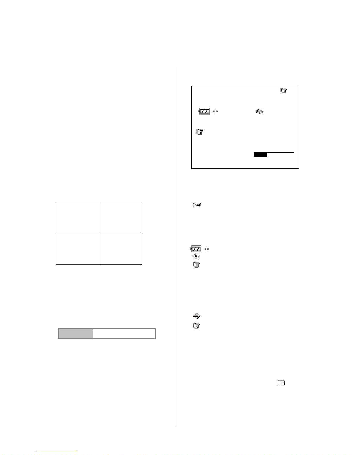
You can display system settings information as
shown on Table 3.3 A below at any time by
pressing the Display button. In the playback
mode, the recorded video information is
displayed. In the live or recording mode, the
Manual Recording information is displayed.
Each sequential press of the Display button
displays a different message detailed in the
following example. By default, the unit displays
time, date, and an indicating bar of capacity
status on a monitor as shown.
Default Display
CH1 , CH2, CH3, CH4 are titles for each
channel, changeable in the Setup menu.
Capacity Status :
( Capacity Used ) ( Capacity Remaining )
01- 01-2005 12:00:00
(Date) (Time)
Press the Display button once, and the DVR
will display the following sample message plus
the default display. Press the Display button
again; the unit will not display any OSD
message. Press the button one more time to
go back to the default display.
Figure 3.3 A.
(HD1: 39G): Total capacity of installed hard disk, 39 GB.
(10.4 HR): Total 10.4 hour recording time available.
(
): Alarm record activated.
(QUALITY: BEST): Record quality setting, BEST.
(NTSC ): NTSC system.
(RATE: 6 HR): Setting of Record time mode, 6 hours.
(20 F/S): Record speed setting, 20 frames/sec.
( ): The current voltage.
(
): Audio function activated.
( ): Indicates which HDD is activated.
( 58K ): The image file size.
( HD ): Hard disk compartment .
( SIZE 39G): The capacity of the installed hard disk.
( REC ): Percentage of system recording position.
( PLAY ): Percentage of system playback position.
( ): External signal.
( x ): Cannot operate now. For example, to press
the SETUP, SEARCH, REW and FF buttons during
the recording mode then the icon will appear.
2.3.2 Channel Selection
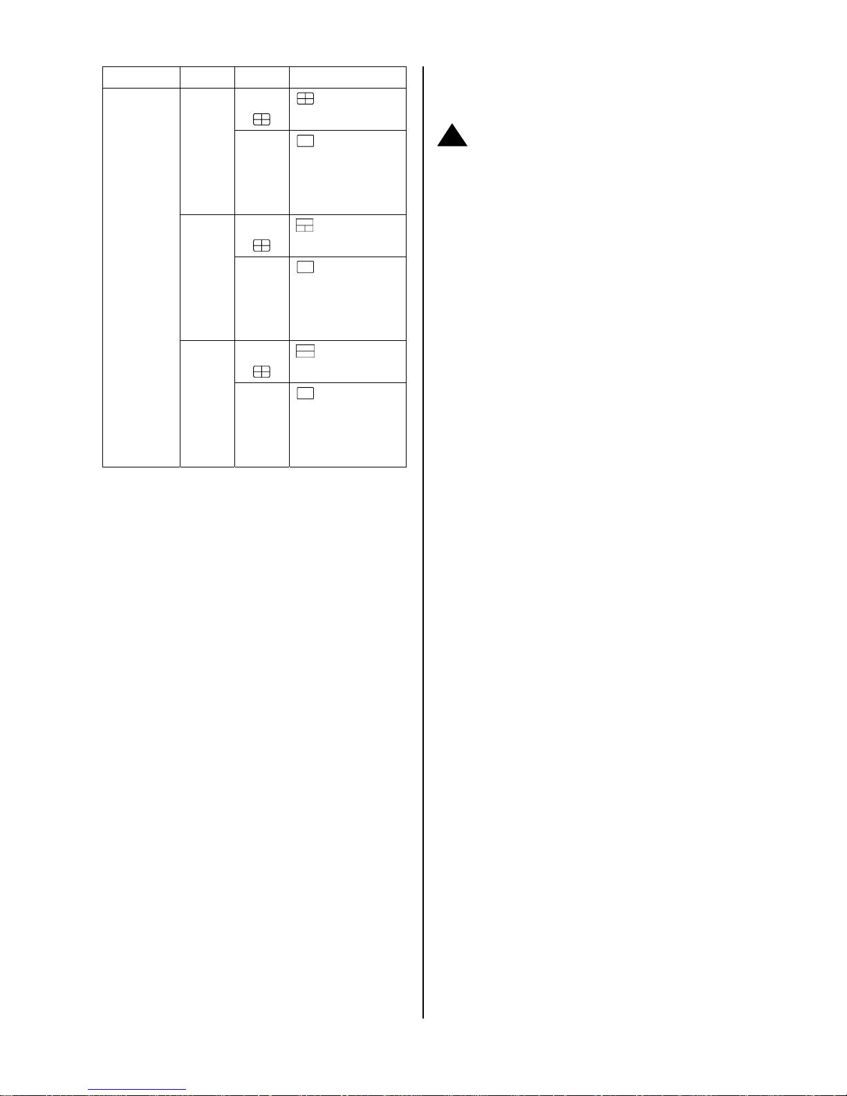
The CH1, CH2, CH3, CH4, and Quad (
)
buttons are used to select single video channels
and the quad mode. The following table shows the
functions under a different mode.
CH1 CH2
CH3 CH4
01/01/2006 12:00:00
HD1 : 39G 10.4 HR x
QUALITY : BEST NTSC
RATE : 6HR 20 F/S
58 K
HD SIZE REC PLAY
1 39G 10.0% 0.1 %
10 / 01 / 2006 15:12:22
Page 21
20
Mode Split Key Result Display
Quad
(
)
4 CH
CH1/
CH2/
CH3/
CH4
( Single
channel )
Quad
(
)
3 CH
CH1/
CH2/
CH3
( Single
channel )
Quad
(
)
Live /
Record /
Playback
2 CH
CH1/
CH2/
( Single
channel )
2.4 Updating System Software
Please take the following steps to safely update
the system software.
1. Turn off the DVR.
2. Insert the SD card into the built-in SD slot of the
unit.
3. Turn on the DVR.
4. The DVR sounds a tone and displays the
message “ XXXXXX BYTES READ”. Now the
DVR is updating the system software, which will
take approximately 90 seconds to process.
5. The DVR displays the message “PLEASE
REMOVE SD CARD”. The process is complete.
Please remove the SD card, and the DVR will
restart automatically. (If you have already followed
procedures 1 ~ 5 and the unit is still unable to turn
on, then please first check if the SD card you are
using is functioning and the file is intact. And then
start procedures 1 ~ 5 all over again.)
6. Verify the version of the system software (please
refer to the section 4.6 VERSION option).
!
Caution:
1. Before carrying out the updating procedures, please
ensure the SD card is working and the file of the
system software is intact.
2. Don’t Interrupt the process while the unit is updating
itself, as this will cause the unit to crash.
Page 22
21
3. OPERATIONS
This section shows you how to operate and
manage the DVR when it gets in the way.
3.1 Configuring Recording
Settings
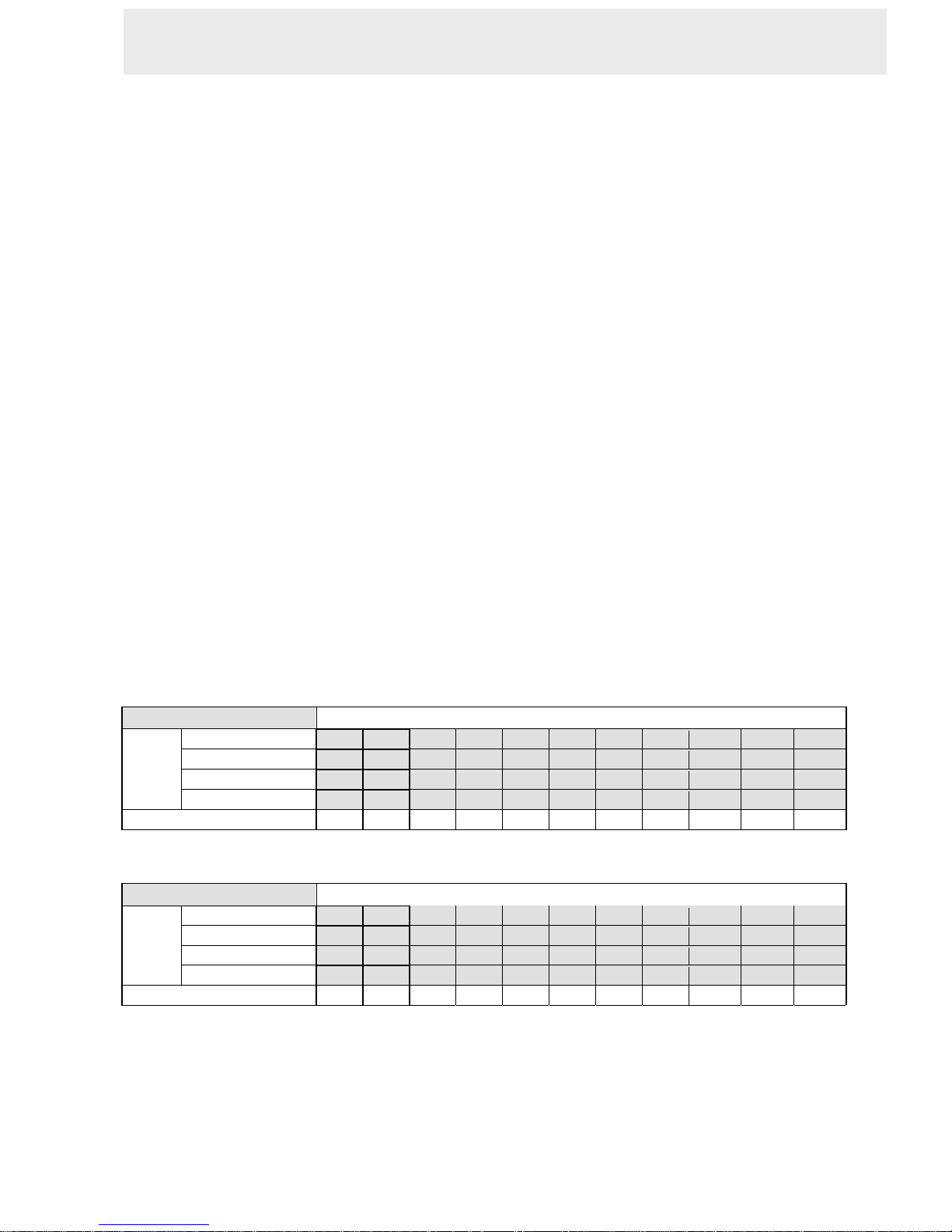
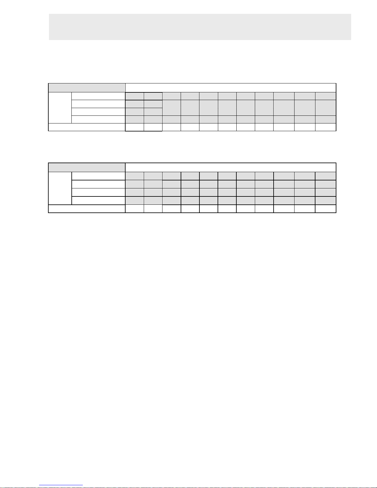
Recording time will vary depending on the image
size, recording rate, and the capacity of the
hard-disk drive. Generally, the DVR comes with a
built-in hard-disk drive for continuous recording
from one to four weeks under most recording
conditions. The table below shows the possible
recording times based on a 20GB hard-disk drive
at certain refresh rates and the corresponding
image quality. With one or more hard-disk drive(s)
in operation, please calculate the recording time
using the table below in accordance with your
requirements. For an NTSC unit, for example, if
the unit is set to record images with BEST quality
at a 30 fps record rate, normally a 20GB
hard-disk drive will be filled in 3.7 hours (see the
gray area in the table). If the total capacity of
80GB hard-disk drive is in use under the same
refresh rate and picture quality, it will be filled in
14.8 hours (4 times the rate of a 20GB hard-disk
drive).
NOTE:
1. Recording times are estimated in the tables
below. For the actual available recording
time of a recording configuration, please
refer to the system information of the DVR.
(Please refer to section 2.3 system
information for more details.)
2. No audio function at the refresh rate in NTSC:
2.7 frames/sec ~ 1 frame/ 16 sec .No audio
function at the refresh rate in PAL: 2.7
frames/sec ~ 1 frame / 16 sec.
NTSC (Audio OFF)
Possible Recording Time HDD=20GB ( hour )
BEST
3.7 6 9 15 33.1 75.3 147.6 256.1 726.3 1088 1449.7
HIGH
4.5 7.2 10.8 18 39.7 90.4 177.2 307.4 871.6 1305.6 1739.7
STANDARD
5.6 9 13.5 22.6 49.7 113.0 221.5 384.2 1089.5 1632.1 2174.6
Image
Quality
BASIC
7.5 11.3 16.9 28.2 62.1 141.2 276.9 480.3 1361.9 2040.1 2718.3
Refresh Rate (Frame/Sec)
30 15 10 6 2.7 1.2 0.61 0.35 1/8 1/12 1/16
NTSC (Audio ON)
Possible Recording Time HDD=20GB ( hour )
BEST
3.7 6 8.9 14.7 - - - - - - -
HIGH
4.5 7.2 10.6 17.6 - - - - - - -
STANDARD
5.6 9 13.2 21.8 - - - - - - -
Image
Quality
BASIC
7.5 11.3 16.5 27.1 - - - - - - -
Refresh Rate (Frame/Sec)
30 15 10 6 2.7 1.2 0.61 0.35 1/8 1/12 1/16
3. OPERATIONS
Page 23
22
PAL (Audio OFF)
Possible Recording Time HDD=20GB ( hour )
BEST
3.8 6 9 15 27.1 51.2 99.4 171.8 605.8 907.2 1208.6
HIGH
4.5 7.2 10.8 18 32.5 61.4 119.3 206.1 726.9 1088.6 1450.3
STANDARD
5.7 9 13.5 22.6 40.6 76.8 149.1 257.7 908.7 1360.8 1812.9
Image
Quality
BASIC
7.7 11.4 17.1 28.5 51.3 97 188.4 325.5 1147.8 1718.9 2290.0
Refresh Rate (Frame/Sec)
25 12.5 8.3 5 2.7 1.4 0.76 0.44 1/8 1/12 1/16
PAL (Audio ON)
Possible Recording Time HDD=20GB ( hour )
BEST
3.8 6 8.9 14.7 - - - - - - -
HIGH
4.5 7.2 10.6 17.6 - - - - - - -
STANDARD
5.7 9 13.2 21.8 - - - - - - -
Image
Quality
BASIC
7.7 11.4 16.7 27.4 - - - - - - -
Refresh Rate (Frame/Sec)
25 12.5 8.3 5 2.7 1.4 0.76 0.44 1/8 1/12 1/16
OPERATIONS ( continued )
Page 24
23
3.2 Recording Operations
This section details the way to record video
into hard-disk drive. Before commencing with
the recording function, please configure the
recording setting properly according to your
needs.
3.2.1 Manual Recording
Take the following steps to start and stop
recording:
(1) Press the REC button to record video into a
hard disk drive with the corresponding
programmed recording settings. The REC
button will light up indicating the DVR is in the
recording status.
(2) Press the STOP button to stop recording any
time.
(3) To access just recorded video, please refer to
section 3.4 for more details.
3.2.2 Alarm Recording
Take the following steps to activate the
programmed alarm recording. For the ALM
OPERATION, REC RATE, REC QUALITY,
AUDIO, ALM TYPE, ALM DURATION, and
PRE-ALARM settings, please refer to section
4.2 for more details.
(1) Press the SETUP button to enter the
MAIN MENU.
(2) Select ALARM and press the Enter
button to enter ALARM.
(3) Set the desired REC RATE, REC QUALITY,
ALM TYPE, and ALM DURATION for use.
If the audio function is required, set AUDIO
to ON. If pre-alarm recording is required, set
PRE-ALARM to ON.
(4) To activate/deactivate the alarm recording,
set ALM OPERATION to ON/ OFF.
3.2.3 Externally Triggered Recording
By connecting the ALARM IN of ALARM I/O on
the rear panel of the DVR, you can activate /
deactivate the alarm recording function of a DVR.
The file will be kept with a prefixed “A”.
NOTE: The status of recording operations
when an alarm takes place is shown in the
diagrams below.
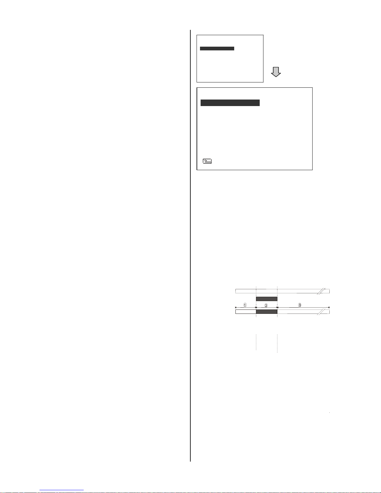
Manual or Externally
Triggered Recording
Alarm Takes Place
Actual Recording
Speed
Normal Alarm Normal
RECORD
ALARM
CLOCK/ TITLE
COMMUNICATION
DISK
SYSTEM
MAIN MENU
GOTO ALARM PAGE
ALM OPERATION
REC RATE
REC QUALITY
AUDIO
ALM TYPE
ALM DURATION
PRE-ALARM
IO CONNECTION
ALARM SETTING
MAIN PAGE
: OFF
: 15 F/S
: BEST
: OFF
: NO
: 30 SEC
: OFF
: ALARM
Page 25

24
3.3 Playback Operations
This section shows you how to operate the fast,
slow, and single-pictu re playback functions,
and details how the unit is to playback a file in
a different operation status. Please refer to the
following paragraphs specifying the relevant
details. When playing a file, the monitor should
display a flashing PLAY message and the
PLAY button will light up indicating that the
DVR is in the playback status.
To switch between channels 1–4 and the quad
view in the playback mode, please press the
CH1, CH 2, CH 3,
CH4 and the buttons.
NOTE: When you press the "PLAY" button
to enter the play mode, you then
press the "SEARCH" button to
change the two audio sources to
any one or two of the cameras you
have.
3.3.1 Normal Playback
Once the user presses the PLAY button, the
DVR will start to playback the recorded data at
the recorded speed; the starting position must
be fixed according to different operation
sequences.
A. Play back from the latest record in the
STOP position.
[ PLAY ] - [ STOP ] - [ PLAY ]
B. Play back from the latest recorded video.
[ REC ] – [ REC Stop ] – [ PLAY ]
C. Play back from a video clip in the Search
List.
[Search] – [ PLAY ]
D. Play back from the beginning of a hard
disk’s recorded data.
[STOP – press the key for 3 sec. ] – PLAY
Once playback reaches the end of an HDD’s
recorded data, the DVR will show the ending
message ( use the SEARCH functions or rewind
to replay the file if required ).
3.3.2 Fast Forward/Backward
There are
7 speeds available for playback: 1x,
2x, 4x, 8x, 16x, 30x and 100x
While playing back recorded video at the
recorded speed:
Forward: Press the FF button to view the
recorded video in the forward direction
at a speed faster than the recorded
speed or to return to the normal speed
of playback. Each subsequent
pressing of the FF button to the right
increases the forward rate, as 2x, 4x,
8x, 16x, 30x and 100x.
Backward: Press the REW button to view the
recorded video in the reverse direction
at a speed faster than the recorded
speed or to return to the normal speed
of playback. Each subsequent pressing
of the REW button to the left increases
the reverse rate, as -1x, -2x, -4x, -8x,
-16x, -30x and -100x.
3.3.3 Slow Forward/Reverse
There are
4 speeds available for a slow
playback: 1/2, 1/4, 1/8, and 1/16.
While playing back recorded video at the
recorded speed:
(1) Press the PAUSE button for the slow
playback mode.
(2) Forward: Press the FF button to view the
recorded video in the forward
direction at a speed slower than the
recorded speed. Each subsequent
pressing of the FF button to the right
increases the forward rate, as 1/2,
1/4, 1/8, and 1/16.
(3) Reverse: Press the REW button to view the
recorded video in the reverse
Page 26

25
FULL LIST
ALARM LIST
TIME SEARCH
THUMBNAIL
SD CARD
SEARCH
FULL LIST
ALARM LIST
TIME SEARCH
THUMBNAIL
SD CARD
SEARCH
direction at a speed slower than the
recorded speed. Each subsequent
pressing of the REW button to the
left increases the reverse rate, as
-1/2, -1/4, -1/8, and -1/16.
(4) Normal: Press the PLAY button to return to
the normal speed of playback.
3.3.4 Play back picture-by-picture
While playing back recorded video at the
recorded speed:
(1) Press the PAUSE button for the pause
mode.
(2) Press the PAUSE button to display one
frame of a picture at a time in the forward
direction, but the PAUSE button can only
function in a forward direction.
(3) Press the PLAY button to return to the
normal speed of playback.
3.4 Search Operations
This section shows you how to access
recorded video.
3.4.1 FULL LIST Search
Take the following steps to proceed with the
full-list search function.
(1) Press the SEARCH button to enter the
search mode.
(2) Select the FULL LIST and press the Enter
button to access the complete list of
recorded video.
(3) Highlight the specific recorded video of
your requirement and press the Enter
button to display the selected video.
(Key Operation: Press the “
^” and “v”
buttons to select a video; press the
“<” and “>” buttons to flip over a
page.)
NOTE: A: Alarm recording.
NOTE: The maximum number of index items in
the list in a hard disk drive is 3000.
3.4.2 ALARM LIST Search
Take the following steps to proceed with the
alarm-list search function.
(1) Press the SEARCH button to enter the
search mode.
(2) Select the ALARM LIST and press the
Enter button to access the complete list of
alarm-event recorded video.
(3) Highlight the specific recorded video of
your requirement and press the Enter
button to display the selected video.
(Key Operation: Press the “
^” and “v”
buttons to select a video; press the “<”
and “>” buttons to flip over a page.)
1 08-11-04 21:47:55 28.3G
2 08-12-04 06:55:58 8.03G
A 3 08-12-04 10:02:15 1.00G
A 4 08-12-04 12:42:31 18.0M
A 5 08-12-04 12:42:47 10.0M
HD1
Page 27
26
FULL LIST
ALARM LIST
TIME SEARCH
THUMBNAIL
SD CARD
SEARCH
FULL LIST
ALARM LIST
TIME SEARCH
THUMBNAIL
SD CARD
SEARCH
MM DD YEAR
10 / 10 / 2004
THUMBNAIL
10 / 01 / 2004 15:10:30
CH 1
MM DD YEAR
10 / 10 / 2004
THUMBNAIL
10 / 01 / 2004 15:10:30
CH 1
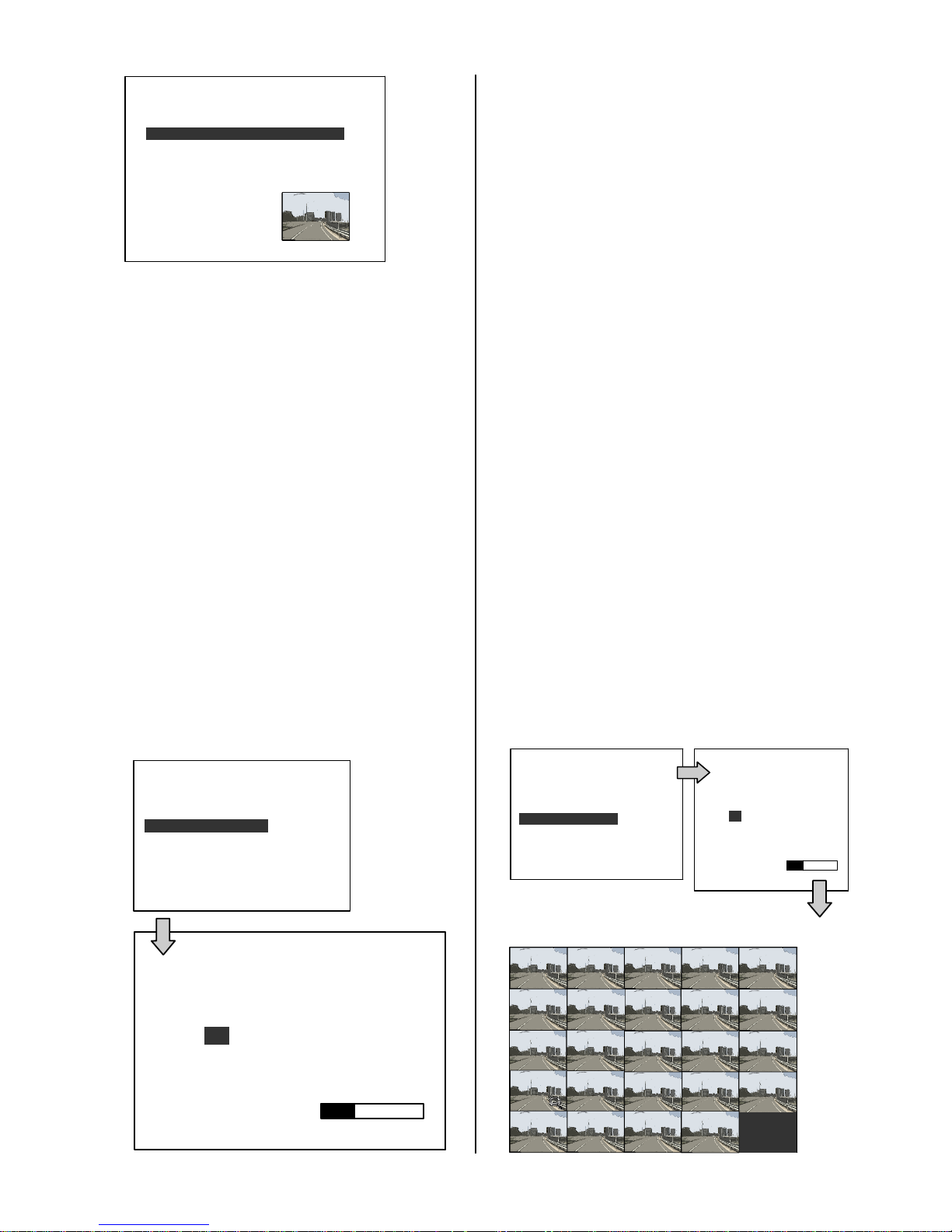
3.4.3 TIME Search
Take the following steps to proceed with the
time-list search function.
(1) Press the SEARCH button to enter the
search mode.
(2) Select the TIME SEARCH and press the
Enter button to access the time-setting
page.
(3) Set the time period you wish to search for
the recorded video.
(4) Press the Enter button to start searching and
displaying the concerned image.
(5) If no video is found, please return to the
time-setting page and repeat steps (3) and
(4) for another search.
\
3.4.4 THUMBNAIL Search
Take the following steps to proceed with the
thumbnail search function.
(1) Press the SEARCH button to enter the
search mode.
(2) Select THUMBNAIL and press the Enter
button to access the thumbnail page.
(3) Set the date you wish to search for the
recorded video.
(4) Press the Enter button to start searching
for and displaying the concerned image.
Note: You can select the image by using
the “<”, “>”, “
^”, “v” buttons to move
the focus.
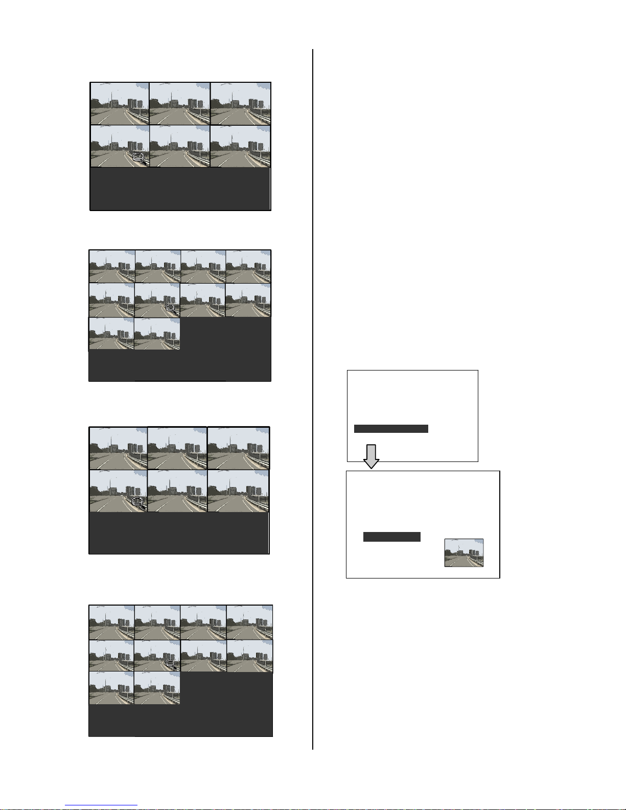
(5) There are
5 levels of recording time
modes to choose from: 1 Hour, 10
Minutes, 1 Minute, 10 Seconds and 1
Second. Select the specific frame of your
requirement and press the Enter button to
enter the next level. If you want to return
to the previous level, please press the
Setup button.
(6) Once you reach the critical point at any
level, you can start to playback by just
clicking the PLAY button.
LEVEL
1 : Interval = 1 Hour
A 1 08-12-04 10:02:15 1.00G
A 2 08-12-04 12:42:31 18.0M
A 3 08-12-04 12:42:47 10.0M
HD1
00:00:00
2004:10:20
LEVEL : 1
1 HR
00:00:00 01:00:00 02:00:00 03:00:00
04:00:00
05:00:00 06:00:00
07:00:00
08:00:00
09:00:00
10:00:00
11:00:00 12:00:00
13:00:00
14:00:00
15:00:00
16:00:00 17:00:00
18:00:00
19:00:00
20:00:00
21:00:00 22:00:00 23:00:00
Page 28
27
FULL LIST
ALARM LIST
TIME SEARCH
THUMBNAIL
SD CARD
SEARCH
LEVEL
2 : Interval = 10 Min.
LEVEL
3 : Interval = 1 Min
LEVEL
4 : Interval = 10 Sec.
LEVEL
5 : Interval = 1 Sec.
3.4.5 The SD CARD Search
Take the following steps to proceed with the
SD card search function.
(1) Insert an SD Card into the SD card slot
on the front panel.
(2) Press the SEARCH button to enter the
search mode.
(3) Select the SD CARD and press the Enter
button to access the complete list of JPG
files.
(4) Highlight the specific JPG file of your
requirement and press the Enter button
to display the image.
(5) If you need another image, please return
to the SD card JPG file list page and
repeat steps 3 and 4 for another search.
NOTE: To delete a JPG file in the SD card,
please return to the SD CARD JPG FILE list
page, highlight the specific JPG file and
press the Setup button, then select “Yes” to
delete the image.
15:20:00
15:30:00
15:40:00
15:50:00
2004:10:20
LEVEL : 2
10 MIN
15:00:00
15:10:00
15:30:00
15:31:00
15:32:00
15:33:00
15:34:00 15:35:00
15:36:00
15:37:00
15:38:00 15:39:00
2004:10:20
LEVEL : 3
1 MIN
15:35:00
15:35:10
15:35:20
15:35:30
15:35:40
15:35:50
2004:10:20
LEVEL : 4
10 SEC
15:35:30
15:35:31
15:35:32
15:35:33
15:35:34 15:35: 35
15:35:36
15:35:37
15:35:38 15:35:39
2004:10:20
LEVEL : 5
1 SEC
F0000.JPG
F0001.JPG
F0002.JPG
F0003.JPG
F0004.JPG
SD CARD JPEG FILE
Page 29

28
3.5 Backup Operations
3.5.1 SD Card Backup Operations
The SD card slot of the front unit has four
functions as shown below:
3.5.1.1 Archive Single image Clips into an SD
Card
Please take the following steps to archive a
critical image in an SD card.
(1) Press the SETUP button to enter the
setup mode and select the DISK.
(2) Highlight DISK and press the
12
Enter button
to enter the DISK SETTING page.
(3) Then set SD FILE to JPEG.
(4) Insert an SD card into the SD card slot of
the front unit.
(5) Start playing back the recorded video.
(6) Press the PAUSE button to freeze the
desired pictures.
(7) Press the SETUP button to save the
image in the SD Card.
The quantity of pictures that can be stored
depends on the SD card capacity. You can
have the saved images printed out in any
computer. The image is stored in the JPEG
compressed format. If more than one clip is
stored in an SD card, the file names will be
assigned in sequence as shown below .
SAVE TO F0000.JPG
SAVE TO F0001.JPG
…
SAVE TO F000N.JPG
(8) The saved picture is the same as the
present picture on the screen; please use
the CH1, CH2, CH3, CH4, and the
12
Quad buttons to switch to the channel(s)
desired, and then press the SETUP
button to save.
3.5.1.2 Archive video of AVI clips into an SD
Card
Please take the following steps to archive a
critical video in an SD card.
(1) Press the SETUP button to enter the setup
mode and select the DISK.
(2) Highlight DISK and press the
12
Enter button
to enter the DISK SETTING page.
(3) Then set SD FILE to AVI.
(4) Insert an SD Card into the SD card slot of
the front unit.
(5) Start playing back the recorded video.
(6) Press the PAUSE button to freeze the
desired pictures.
(7) Press the SETUP button to save the
video in the SD card.
The quantity of video that can be stored depends on
the SD card’s capacity. The image is stored in the
A V I compressed format. If more than one clip is
stored in an SD card, the file names will be
assigned in sequence as shown below .
SAVE TO M0000.AVI
SAVE TO M0001.AVI
…
SAVE TO M000N.AVI
NOTE:
●The JPEG file format can be played and deleted in
the DVR. Please refer to section 3.4.5.
●The AVI file format cannot be played and deleted in
the DVR. It can only be played in a card reader
connected to a computer.
●The file format can be selected from the “SD FILE”
item on the Setup Menu. Please refer to section 4.5
for more details.
Backup the System setting info into an SD
Card.
The DVR offers a quick setup method by
using an SD card. If a user wants to set many
DVR devices with the same settings, the DVR
can save the whole setting in the SD card,
and then transfer it to another DVR.
RECORD
ALARM
CLOCK/ TITLE
COMMUNICATION
DISK
SYSTEM
MAIN MENU
GOTO SYSTEM PAGE
Page 30

29
OPERATION LOG
OSD LANGUAGE
MENU BACKGND
BUZZER
PAS SWO RD
SETUP PWD
DEFAULT
SD SETUP
VERSION
SYSTEM
MAIN PAGE
SAVE
LOAD
Save the whole setting into the SD card:
Insert an SD card into the SD card slot.
Press the SETUP button to enter the setup
mode.
Highlight SYSTEM and press the Enter button
to enter the SYSTEM SETTING page.
Set SD SETUP to SAVE. Then the system
setting information will be automatically
saved in the SD card.
Transfer the system setting info of the DVR
to another DVR:
Insert the SD ca rd which has stored the
system setting information into the DVR.
Press the SETUP button to enter the setup
mode and select SYSTEM.
Highlight SYSTEM and press the Enter button
to enter the SYSTEM SETTING page.
Then set SD SETUP to LOAD.
3.5.1.4 Updating the System Software
Please refer to section 4.6 for more details.
3.6 The Key Lock Operation
The Key lock operation protects the unit
against unauthorized use by disabling the
entire front panel controls. Press the Enter
button for at least 3 seconds to lock the unit;
to release the Key Lock, press the button
again and enter the pre-set password (or the
standard password if this is the initial setting).
Page 31
30
4. MENU SETUP
4. MENU SETUP
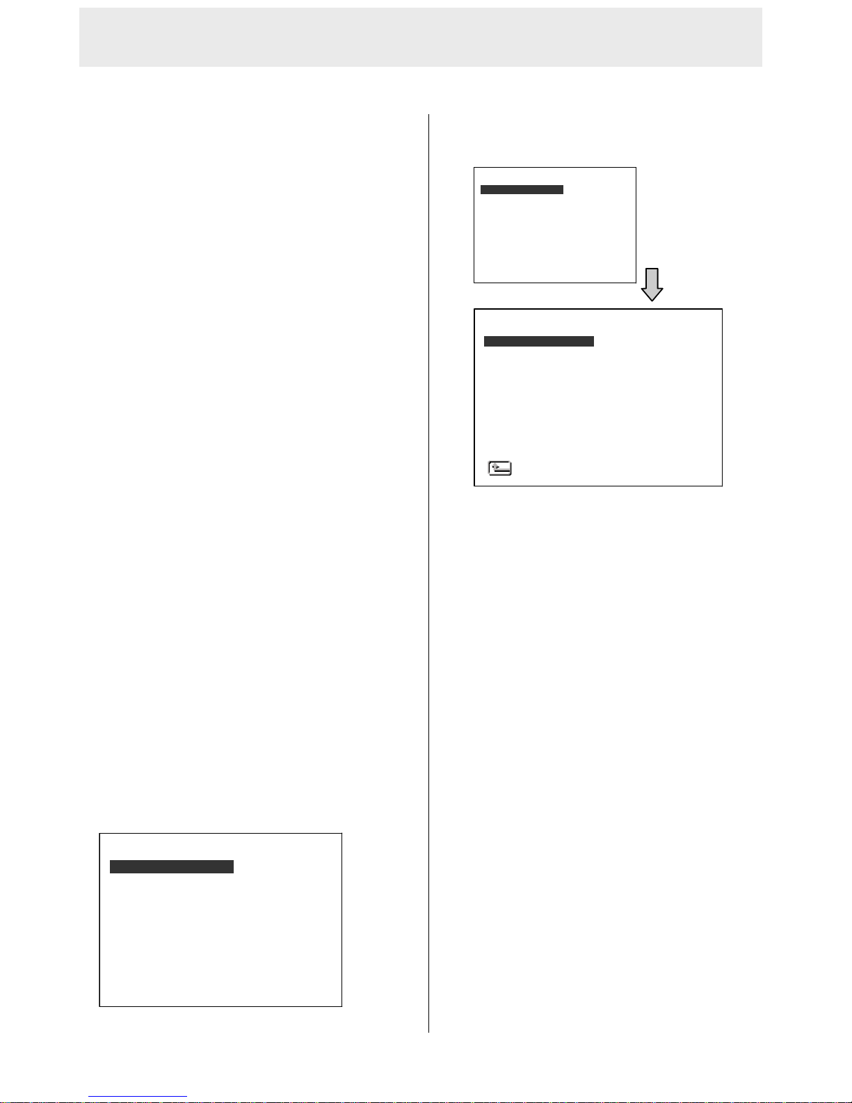
There are 6 categories for operation setting in the setup
menu system as shown below. The following sections
will instruct you step by step to configure the operation
settings and state each menu’s pu rpose and options.
Press the Setup button to access the setup menu. Once
inside the menu system, the on-screen menu allows you
to set up the key features of the unit. The functions of
various buttons within the menu-setup mode are
described in the paragraphs below.
KEY FUNCTIONS
Setup button:
Press to enter the setup menu. Press again to exit the
setup mode.
“
^” and “v” buttons:
Press to select the desired item or entry for setting.
“<” and “>” buttons:
Press to highlight the desired option or to select the
context for setting.
Enter button:
Press to enter the selected item and to save the
setting.
4.1 REC Setting
This page allows you to set the recording rate and
recording quality, and enables you to continue
recording when the disk is full.
AUTO START REC :
This option is for setting the start-recording function
while power on the DVR.
OFF: Inactivate the function.
O SEC: Start recording immediately when turning
on the DVR.
1 MIN: Start to record after power on the DVR for 1
minute.
REC RATE:
This option is for adjusting the number of pictures
recorded every second into a storage disk. The
recording rate controls the frequency at which the
number of video pictures can be recorded.
For an NTSC unit, there are 11 different recording
rates you can select from: 30F/S (30 frames per
second), 15F/S, 10F/S, 6F/S, 2.7F/S, 1.2F/S,
0.61F/S, 0.35F/S, 1 F/8S, 1F/12S, and 1F/16S.
For a PAL unit, there are 11 different recording
rates you can select from: 25F/S (25 frame per
second), 12.5F/S, 8.3F/S, 5F/S, 2.7F/S, 1.4F/S,
0.76F/S, 0.44F/S, 1 F/8S, 1F/12S, and 1F/16S.
Please refer to the table in section 3.1 for details.
RECORD
ALARM
CLOCK/ TITLE
COMMUNICATION
DISK
SYSTEM
MAIN MENU
GOTO REC PAGE
AUTO START REC
REC RATE
REC QUALITY
DISK FULL
AUDIO
POST-REC DURATION
SPLIT
A/V SOURCE
REC SETTING
MAIN PAGE
: OFF
: 20 F/S
: BEST
: REWRITE
: OFF
: OFF
: 4CH
: SET
RECORD
ALARM
CLOCK/ TITLE
COMMUNICATION
DISK
SYSTEM
MAIN MENU
GOTO REC PAGE
Page 32

31
REC QUALITY:
This option determines the image quality to be
recorded. The DVR stores images in the
compressed format and allows the image quality
to be altered by the image size. There are 4 levels
of image quality you can select from: BEST,
HIGH, STANDARD, and BASIC. Selecting the
BEST image for use provides higher-resolution
recorded images, and normally takes up more
storage space than a HIGH, STANDARD or
BASIC image does.
DISK FULL:
This option determines the way to utilize storage
media in case of a full disk.
REWRITE: When the hard disk is full, the device
continues recording by displacing the old data.
STOP: When the hard -disk is full, the device will
stop recording.
AUDIO:
This option determines the way to record sound if
necessary.
OFF: Disables AUDIO recording.
11KHZ: Enables AUDIO recording and records at
the 1 1KHz sampling rate.
22KHZ: Enables AUDIO re cording and records at
the 22KHz sampling rate.
NOTE: The audio function can only be activated in
the following refresh rates in NTSC(PAL): 30(25),
15(12.5), 10(8.3), 6(5),and 2.7(2.7) frames/sec.
POST REC DURATION:
This option determines the duration of the
recording after the ACC is off. There are six
options here you can select from: OFF, 1 MIN, 5
MIN, 10 MIN, 60 MIN, 90 MIN, 120 MIN and NON
STOP.
OFF: The recording will stop automatically when the
vehicle motor is turned off.
1 MIN: There will be automatic recording for a
minute after the vehicle motor is switched off.
5 MIN: There will be automatic recording for five
minutes after the vehicle motor is switched off.
10 MIN: There will be automatic recording for ten
minutes after the vehicle motor is turned off.
60MIN: There will be automatic recording for one
hour after the vehicle motor is turned off.
90 MIN: There will be automatic recording for 90
minutes after the vehicle motor is turned off.
120 MIN: There will be automatic recording for 120
minutes after the vehicle motor is turned off.
NON-STOP: This option allows for continuous
recording after a vehicle's motor has been switched
off. However, its functioning depends on the amount
of power the vehicle has available to it, so it can run
only as long as there is power. Enough power will be
left untapped by this option to turn the vehicle motor
on the next time the user starts it.
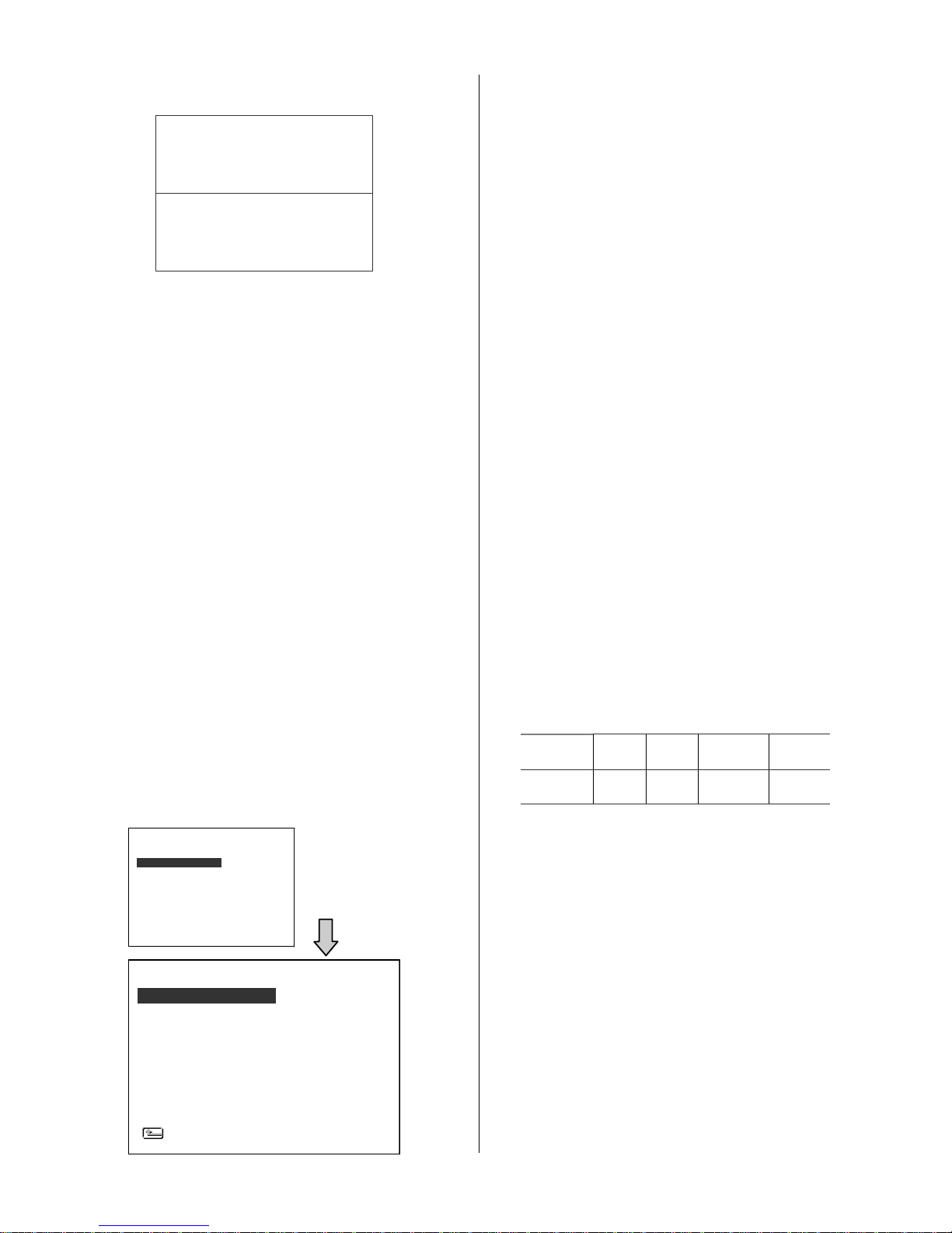
SPLIT:
This option determines the layout of the screen. You
can select from 4CH, 3CH, and 2CH. The resulting
layout on the screen will be as follows.
4 CH: This option splits the screen in the quad
mode.
3 CH: This option splits the screen in three
channels.
CH1 CH2
CH3 CH4
01/01/2006 12:00:00
CH1
CH2 CH3
01/01/2006 12:00:00
MENU SETUP ( continued )
Page 33
32
2 CH: This option splits the screen in two channels.
A/V SOURCE:
This page determines the video and the audio sour ce.
Choose the channel and the audio/ video numbers
you want to see. Only four channels are available,
each with four video inputs and four video outputs
which you can select from and set; these same four
channels have six audio inputs and two audio outputs
you can select from and set. This "A/V SOURCE"
page lets you set two audio outputs: AUDIO 1 and 2,
which have six microphone sources each which you
can choose from, four from the video cameras and
two from the AUX ( auxiliary ) microphones. You can
only set two microphones to play. Each of the ports,
AUDIO 1 and 2, can play the sound recordings of the
same or different videos simultaneously.
4.2 The ALARM Setting
This menu allows users to program the
configuration of the alarm recording only when an
alarm input is activated. The device will record as
long as the alarm input is activated.
ALM OPERATION:
This option determines whether to activate/deactivate
the alarm recording when it detects an alarm input.
ON: The device activates the alarm recording when
it detects an alarm input.
OFF: The device ignores the alarm signal when it
detects an alarm input.
REC RATE:
This option is for the purpose of adjusting the
number of pictures recorded every second into a
storage disk when an alarm input is activated. For
an NTSC unit, there are 5 different record speeds
you can select from: 30F/S (30 frames per
second), 15F/S, 10F/S, 6F/S, and REMAIN. For a
PAL unit, there are 5 different record speeds you
can select from: 25F/S (25 frames per second),
12.5F/S, 8.3F/S, 5F/S, and REMAIN. If you select
REMAIN for use, the device will record images at
the same speed as set on the REC page.
REC QUALITY:
This option determines the image quality to be
recorded when an alarm input occurs. There are 4
levels of image quality to choose from: BEST,
HIGH, STANDARD, and BASIC. The table below
shows the level of image quality with the
corresponding compression ratio and image size.
REC
Quality
Best High Standard Basic
Image
Size
60KB 50KB 40KB 32KB
AUDIO:
This option determines the way to record sound if
or as necessary.
OFF: Disables the AUDIO recording.
11KHZ: Enables the AUDIO re cording and records
at the 1 1KHz sampling rate.
22KHZ: Enables AUDIO re cording and records at
the 22KHz sampling rate.
NOTE: The audio function can only be activated in
the following refresh rates in NTSC(PAL): 30(25),
15(12.5), 10(8.3), and 6(5) frames/sec.
ALM TYPE:
This option allows users to set a type of alarm
input corresponding to the sensor signal in use.
NO: Normally Open. This is to be used with the
CH1
CH2
01/01/2006 12:00:00
RECORD
ALARM
CLOCK/ TITLE
COMMUNICATION
DISK
SYSTEM
MAIN MENU
GOTO ALARM PAGE
ALM OPERATION
REC RATE
REC QUALITY
AUDIO
ALM TYPE
ALM DURATION
PRE-ALARM
IO CONNECTION
ALARM SETTING
MAIN PAGE
: OFF
: 15 F/S
: BEST
: OFF
: NO
: 30 SEC
: OFF
: ALARM
Page 34
33
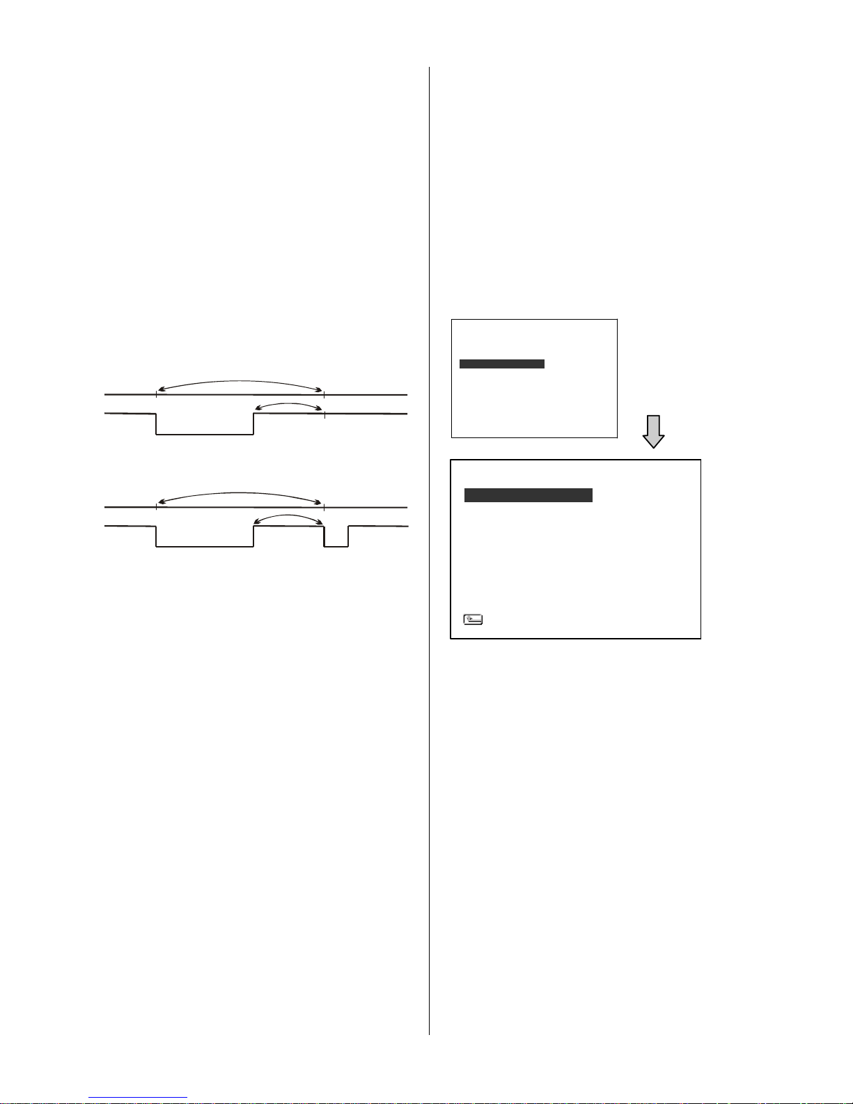
Duration
Setting
Alarm
activated
Alarm
deactivated
Reset
Alarm recording
Non-Stop
Alarm
activated
Alarm
deactivated
Duration
Alarm recording
Duration
CLOCK
DAYLIGHT SAVING
TITLE
DELAY ON
DELAY OFF
CLOCK / TITLE
MAIN PAGE
: SET
: OFF
: SET
: OFF
: OFF
type of alarm sensor whose contact remains
open in normal conditions and closes in case
of activation.
NC: Normally Closed. This is to be used with the
type of alarm sensor whose contact remains
closed in normal conditions and opens in
case of activation.
ALM DURATION:
This option allows users to set alarms for a certain
duration. You can select one of the six following
options: 0 SEC, 30SEC, 1 MIN, 5 MIN, 10 MIN,
and NON-STOP.
PRE- ALARM:
This option determines that images before an
alarm occurs will be recorded in the hard-disk drive.
When an alarm is triggered the device will record
the image prior to the alarm for 50 images. (
10
frame/ sec
)
ON: Enables this function.
OFF: Disables this function.
NOTE: If the device is already in the recording
mode before an alarm occurs, the pre-alarm
recording will not take effect.
I/O CONNECTION:
This item is for the setting of the I/O connection.
( Please ref. to 1.7 ) Here you have two options of
determining your connection.
ALARM: This item connects you with an alarm
sensor.
Set the 4 inputs of the I/O connection
as ALM1/ ALM2/ ALM3/ RESET. The Alarm
signals are used to trigger the alarm
recording.
VEHICLE SIGNAL: Set the 4 inputs of the I/O
connection as LEFT/ RIGHT/ not applicable /
BRAKE. The vehicle signals will be recorded
with the video data.
4.3 The CLOCK/ TITLE Setting
This option allows you to set the system time, the
daylight saving time and the power delay time. This
option also allows users to set the titles for each
video source or camera, in live or recording mode.
CLOCK:
This entry allows users to set the system time.
NOTE: The clock data is retained for about 3 months
after the 15-hour power supply is used up (in the
Operate On mode).
DAYLIGHT SAVING
This entry allows users to set the daylight saving
time.
OFF: This disables the daylight saving time.
US: Daylight saving time begins at 2:00 a.m. on the
first Sunday of April. The time reverts to standard
time at 2:00 a.m. on the last Sunday of October.
EUROPE: ( Except UK ) Daylight saving time
begins at 2:00 a.m. on the last Sunday of March.
The time reverts to standard time at 2:00 a.m. on
the last Sunday of October.
UK: Daylight saving time begins at 1:00 a.m. on
the last Sunday of March. The time reverts to
standard time at 1:00 a.m. on the last Sunday of
October.
RECORD
ALARM
CLOCK/ TITLE
COMMUNICATION
DISK
SYSTEM
MAIN MENU
GOTO CLOCK/ TIMER PAGE
Page 35
34
HD REFORMAT
HD FAT32
SD FILE
AUTO ERASE
SD REFORMAT
DISK SETTING
MAIN PAGE
: HD1
: BUILD
: JPEG
: OFF
: START
COMM ID
RS232 ENABLE
RS232 CONNECTION
BAUD
COMM SETTING
MAIN PAGE
: 0 1
: ON
: DATA BOX
: 9600
DEVICE [ DVR ]
CH1 [ FRONT ]
CH2 [ RIGHT ]
CH3 [ BACK ]
CH4 [ LEFT ]
TITLE
TO MOVE TO CHANGE
SET: This sets the beginning and the end of the
daylight saving time.
TITLE:
This entry allows users to set the titles for each
video source or camera, in live or recording mode;
press the DISPLAY button to switch on the display
status to show the titles. The maximum length for
each title is 24 letters.
DELAY ON:
This entry sets the delay time of the relay on after
the DVR powers up. The selectable options are
OFF, 0 SEC, 1 MIN, 5 MIN and 10 MIN
DELAY OFF:
This entry sets the delay time of the relay off after
the DVR powers off. The selectable o ptions are
OFF, 1 MIN, 5 MIN, 10 MIN, 60 MIN and NON
STOP.
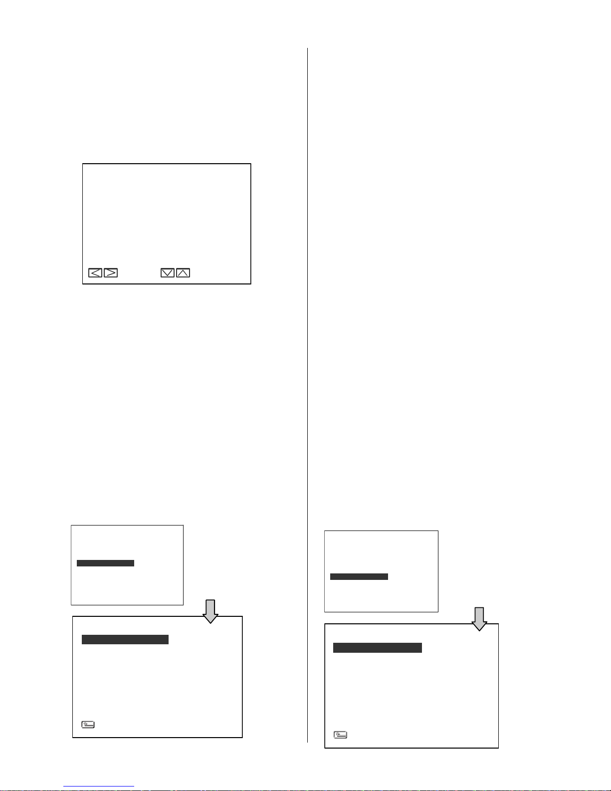
4.4 The COMMUNICATION Setting
Please refer to 6.1 RS-232 Protocols for more details.
COMM ID:
This is the Communication ID for the RS232
communication. After the DVR
receives a RS232
command, it checks if the <Dest ID> within the
code is the same as the COMM ID, in which case
the particular command can be accepted.
RS-232 ENABLE:
The RS-232 communication port can be either in
an importing or exporting mode according to your
applications.
ON: This enables the RS-232 communication port.
When you wish the unit to be controlled by
an external device, please select this entry
for use.
OFF: This disables the RS-232 communication
port.
RS-232 CONNECTION:
This item lets you control the following:
GPS: Use the GPS connector with the GPS
receiver.
Note: Refer to 1.5.4 for more information
about the correct pin assignment.
DATA BOX: Use the DATA BOX connector if the
mobile DVR is compatible with it. Use it if
you want to connect only with the RS 232
port directly without using the GPS
connectors.
Note: You can select only one of the functions
between GPS or DATA BOX
simultaneously.
BAUD:
This entry selects the baud rate of the RS232 port.
The selectable options are 2400, 4800, 9600,
19200, 28800, 38400, 57600 and 115200.
4.5 DISK Setting
RECORD
ALARM
CLOCK/ TITLE
COMMUNICATION
DISK
SYSTEM
MAIN MENU
GOTO COMM PAGE
RECORD
ALARM
CLOCK/ TITLE
COMMUNICATION
DISK
SYSTEM
MAIN MENU
GOTO DISK PAGE
Page 36
35
OPERATION LOG
MENU BACKGND
BUZZER
PASSWORD
SETUP PWD
DEFAULT
SD SETUP
VERSION
SYSTEM
MAIN PAGE
: ENTER
: 2
: OFF
: SET
: OFF
: LOAD
: SAVE
: ENTER
OPERATION LOG
MENU BACKGND
BUZZER
PAS SWOR D
SETUP PWD
DEFAULT
SD SETUP
VERSION
SYSTEM
MAIN PAGE
: ENTER
: 2
: OFF
: SET
: OFF
: LOAD
: SAVE
: ENTER
05/15/04 18:19:30
05/15/04 18:19:36
05/15/04 18:23:10
05/15/04 18:23:50
05/15/04 18:25:05
05/15/04 18:27:12
05/15/04 18:50:30
05/15/04 18:51:20
LOG
ON
OFF
ON
REC
STOP
V-LOSS
PLAY
STOP-P
RECORD
ALARM
CLOCK/ TITLE
COMMUNICATION
DISK
SYSTEM
MAIN MENU
GOTO SYSTEM PAGE
HD REFORMAT:
This option allows you to clear out all the data in the
hard-disk drive. You will be required to enter the
pre-set password before proceeding with clearing out
the data. Enter the standard password “9999” if you
haven’t set your individual password. To set your
individual password, please refer to the section 4.6
System Setting - PASSWORD option.
HD 1: Clears out all the data stored in HD 1.
HD FAT32:
This function builds the FAT32 file system in the hard
disk, so the data in the hard disk can be played back
in a PC.
SD FILE:
This option determines the format to save important
image files in an SD card.
JPEG: Archives images in the JPEG format, to
save a single picture in every file.
AVI : Archives images in the AVI format, to save a
sequence of images in a file, the maximum
limit being 300 images for every file. You can
stop recording whenever you want, and if
you don’t, recording will automatically stop
at the optimum of
300 images.
NOTE: To save images, please refer to section 3.5.1 for
more details.
AUTO ERASE:
This item offers you two options.
OFF: Choosing this alternative disables the "AUTO
ERASE" function.
SET: This choice enables the "AUTO ERASE"
function. Select "SET" and press the ENTER
button to enter the "AUTO ERASE SETTING"
page, where you can enable the settings to
save data for storage for any period of time
from 1 to 365 days. After the expiry of the time
period you set, the data will be erased
automatically. This process of storage and
erasure over the time period you set will be
repeated indefinitely until you disable the
settings or change the settings to a different
time period.
SD REFORMAT:
This option allows you to clear out all the data in the
SD Card.
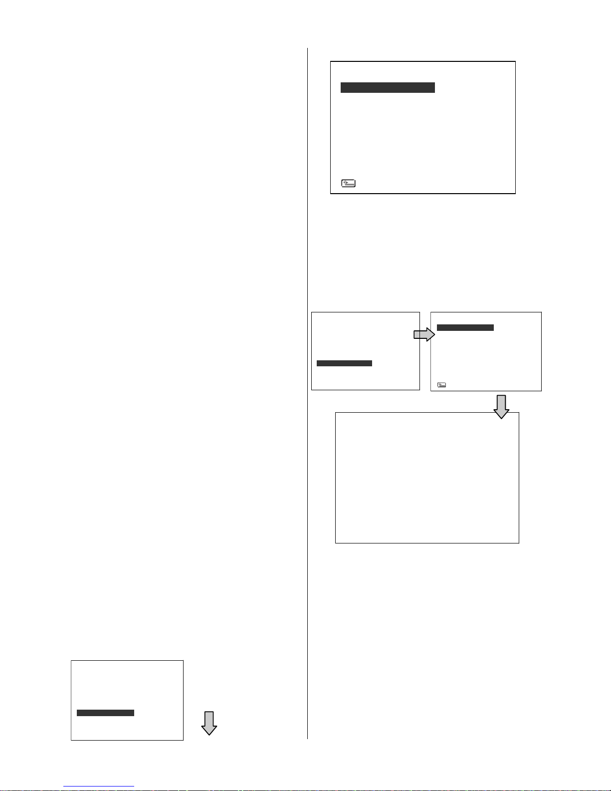
4.6 The SYSTEM Setting
This page is used for accessing the history of the
operation status, setting the password, resuming fa ctory
default, and determining the menu display background.
OPERATION LOG:
This log shows the history of the operation status in
chronological order. What the following entries
represent is detailed below.
ON: Powers on the device.
OFF: Powers off the device.
REC: Starts recording.
STOP: Ceases recording.
STOP-P: Ceases playback.
PLAY: Shows recorded video.
V-IN: Video input is connected.
V-LOSS: Video loss occurs.
P-LOSS: Power interruption occurs.
RECORD
ALARM
CLOCK/ TITLE
COMMUNICATION
DISK
SYSTEM
MAIN MENU
GOTO SYSTEM PAGE
Page 37

36
SW : 1.21
DATE : Nov 10 2006
KEY : 1.00
REAR: 1.09
VERSION
A-IN: Detects an alarm input.
LOCK:
Disables the entire front panel controls.
UNLOCK:
Releases the key lock.
UPDATE:
Updates system software.
ACC ON: Vehicle Ignition ON.
ACC Off: Vehicle Ignition OFF.
OFF-BL: Power off because of the low voltage
of battery.
OFF-BH: Power off because of the high voltage
of battery.
Note: The log keeps an operation history on a revolving
basis because of a limit of 4000. When the log is
full, the newly registered record of an operation
will replace the existing records starting with the
oldest record.
MENU BACKGND:
There are
3 levels of background color
transparency you can choose from: level 1 is totally
transparent, level 3 is opaque, and level 2 is
between levels 1 and 3. The background color is
used in the setup menu and search functions.
BUZZER:
This option determines the embedded buzzer will
sound a tone to signal the following situations. A
tone lasts about two seconds long.
ON: Enables the buzzer.
OFF: Disables the buzzer.
Situation
Alarm occurs
Video loss occurs
Disk is full
Load factory default
Buzzer set to ON
Key lock function enabled/disabled
Power on /off
PASSWORD:
This option allows you to set a password to prevent
any unauthorized re-formatting of the hard disk
drive and to unlock the entire front panel button
controls. The standard password is “9999”.
OLD PASSWORD: Enter the pre-set password (or
the standard password if this is the initial
setting) to access the password setting
system.
NEW PASSWORD: Enter a 4-digit-number
password of your choosing which will
replace the pre-set password (or the
standard password “9999” ).
SETUP PWD:
When this option is on, the user must pass the
password check before entering the setup menu.
ON: Enables the password protection for the setup
menu.
OFF: Disables the password protection for the
setup menu.
DEFAULT:
This option allows you to reload the factory default
setting. Please do note that the password cannot
be changed in the factory default setting.
SD SETUP:
The DVR offers a quick setup method by using an
SD card. If the user wants to set up a number of the
same devices with the same settings, he can save
the whole settings to an SD card, and then transfer
them to another DVR.
SAVE: Saves the whole setting to the SD
card.
LOAD: Loads the whole setting from the SD
card.
VERSION:
This item is in the setup menu: it shows the BIOS
version, the software version, the last updated date,
and the software version of the key board and the
rear board.
Page 38
37
6. OTHER
5.1 The RS-232 Setup & Protocol
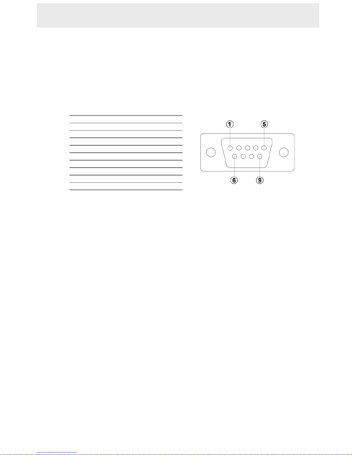
5.1.1 The RS-232 Protocol
Use a Null Modem cable (the standard RS-232 9 Pin Cable with Pin 2 and Pin 3 exchanged ;
see the pin configuration chart below for details) to connect the rear panel of the DVR.
PIN NO.
PIN Assignment
1.
Not Connected
2.
RX
3.
TX
4.
Not Connected
5.
Ground
6.
Not Connected
7.
Not Connected
8.
Not Connected
9.
Not Connected
Set the RS-232 option to ON in the COMMUNICATION page of the setup menu.
The transmission protocol is 8 data bit: 1 start bit, 1 stop bit and no p arity. 8 different speeds
can be used: 2400 baud per second, 4800 baud, 9600 baud, 19200 baud, 28800 baud, 38400
baud, 57600 baud and 115200 baud. The default setting is 9600 baud per second.
5.1.2 The Communication Protocol
5.1.2.0 General Command Format
<Lead Code = 0x41>, < Dest ID >, < Src ID >, <Main category >, <Second category >,
{<Number of parameters>, <Parameter 1>, <Parameter 2> ..,} <End Code= 0x4f>
Lead Code = 0x41
Dest ID = 0x01
Src ID = 0x20
Main Category = 0x01 Keys and Signals
= 0x02 Command
Second Category = 0x01 Handshake
= 0x02 Request Time/Set Time
= 0x06 Request System State
= 0x0b Time Search
= 0x10 Request HDD Info
= 0x11 Request REC Position
= 0x12 Playback Immediately
End Code= 0x4f
The different command types and their corresponding parameters are as follows:
5. MISCELLANEOUS
Page 39

38
5.1.2.1 Keys and signals ( Main Category = 0x01 )
PC Send: <0x41>, <0x01>, <0x20>, <0x01>, <Key Value>, <0x4f>
< The value of a specific front panel key >
DEC HEX
KEY_PLAY 1 0x01
KEY_STOP 3 0x 03
KEY_PAUSE 4 0x 04
KEY_REC 6 0x 06
KEY_SETUP 7 0x 07
KEY_ENTER 8 0x 08
KEY_SEARCH 10 0x 0A
KEY_DISPLAY 11 0x 0B
KEY_UP 13 0x 0D
KEY_DOWN 14 0x 0E
KEY_LEFT 15 0x 0F
KEY_RIGHT 16 0x 10
KEY_SCAN_F 19 0x 13
KEY_SCAN_R 20 0x 14
SIGNAL_REC_IN 163 0x A3
SIGNAL_ALARM_RESET 165 0x A5
SIGNAL_REC_OUT 169 0x A9
SIGNAL_ALARM_IN 189 0x BD
SIGNAL_ALM1_IN 193 0x C1
SIGNAL_ALM2_IN 194 0x C2
SIGNAL_ALM3_IN 195 0x C3
SIGNAL_ALM4_IN 196 0x C4
SIGNAL_ALARM_OU 209 0x D1
SIGNAL_ALM2_OUT 210 0x D2
SIGNAL_ALM3_OUT 211 0x D3
SIGNAL_ALM4_OUT 212 0x D4
SIGNAL_HELP 239 0x EF
5.1.2.2 COMMAND (Main Category=0x02)
A. Handshake (Second Category=0x01)
PC Request: <0x41>, <0x01>, <0x20>, <0x02>, <0x01>, <0x00>, <0x4f>
DVR Response: <0x41>, <0x20>, <0x01>, <0x02>, <0x08>, <0x00>, <0x4f>
B. Request Time (Second Category=0x02)
PC Request: <0x41>, <0x01>, <0x20>, <0x02>, <0x02>, <0x00>, <0x4f>
DVR Response: <0x41>, <0x20>, <0x01>, <0x02>, <0x02>, <0x07>, <7 Time
V alue >, <0x4f >
The following case is an illustration of < 7 Time Value>
2004/06/20 17:05:00 = <0xD4>, <0x07>, <0x06>, <0x14>, <0x11>, <0x05>, <0x00>
C. Set Time (Second Category=0x02)
PC Request: <0x41>, <0x01>, <0x20>, <0x02>, <0x02>, <0x07>, < 7 Time Value >,
<0x4f>
The following case is an illustration of < 7 Time Value>
2004/06/20 17:05:00 = <0xD4>, <0x07>, <0x06>, <0x14>, <0x11>, <0x05>, <0x00>
MISCELLANEOUS ( continued )
Page 40

39
DVR Act: Changing the time and date.
D. Request State (Second Category=0x06)
PC Request: <0x41>, <0x01>, <0x20>, <0x02>, <0x06>, <0x00>, <0x4f>
DVR Response: <0x41>, <0x20>, <0x01>, <0x02>, <0x06>, <0x01>, <System
State = 0..>, <0x4f>
Description of <System State>:
STATE_STOP 0
STATE_PLAY 3
STATE_SETUP 6
STATE_SEARCH 7
STATE_BACKUP 15
E. Time Search (Second Category=0x0b)
PC send: <0x41>, <0x01>, <0x20>, <0x02>, <0x0b>, <0x06>, <6 Bytes Date/Time>,
<0x4f> where < 6 bytes Date/Time >, = year (2 bytes, =LowByte + HighByte*256),
month (1 byte), day (1 byte), hour (1 byte), min (1 byte)
Example: to search 06/12/2004 17:00 the Date/Time = <0xd4>, <0x07>, <0x0 6>,
<0x0c>, <0x11>, <0x00> where 2004= 212(=0xd4) + 7(=0x07) *256
F. Request HDD Info (Second Category=0x10)
PC send: <0x41>, <0x01>, <0x20>, <0x02>, <0x10>, <0x00>, <0x4f>
DVR Response: <0x41>, <0x20>, <0x01>, <0x02>, <0x10>, <0x32>, <0x00>,
<0x00>, <48 Bytes Data> <0x4f>
<48 Bytes Data>=4 HDD Status( Primary Master/Slave, Secondary Master/Slave )
Every HDD use 12 Bytes=
#0 :HDD Exist ( if = 1 )
#1 :Active HDD ( if = 1 )
#2 :Current HDD for REC ( if = 1 )
#3 :Current HDD for PLAY ( if = 1 )
#4…#7 :Capacity
#8.. #11 :REC/PLAY Position
G. Request REC Position (Second Category=0x11)
PC send: <0x41>, <0x01>, <0x20>, <0x02>, <0x1 1>, <0x00>, <0x4f>
REC Mode
DVR Response: <0x41>, <0x20>, <0x01>, <0x02>, <0x1 1>, <0x08>, <HDD#>,
<0x0>, <4 Bytes REC Position>, <2 Bytes Image NO.>, <0x4f>
Get HDD#, REC Position and Image NO. used in Playback Immediately command
Non REC Mode
DVR Response ERROR: <0x41>, <0x20>, <0x01>, <0x02>, <0x11>, <0x01>, <0x45>,
<0x4f>
H. Playback Immediately (Second Category=0x12)
PC send: <0x41>, <0x01>, <0x20>, <0x02>, <0x12>, <0x0a>,<HDD#>, <0x0>,
<0x0>, <0x0>,<4 Bytes REC Position>, <2 Bytes Image NO.>, <0x4f>
On Success
DVR Response: <0x41>, <0x20>, <0x01>, <0x02>, <0x12>, <0x00>, <0x4f>
On Error
DVR Response ERROR: <0x41>, <0x20>, <0x01>, <0x02>, <0x12>, <0x01>,
<0x45>, <0x4f>
Page 41
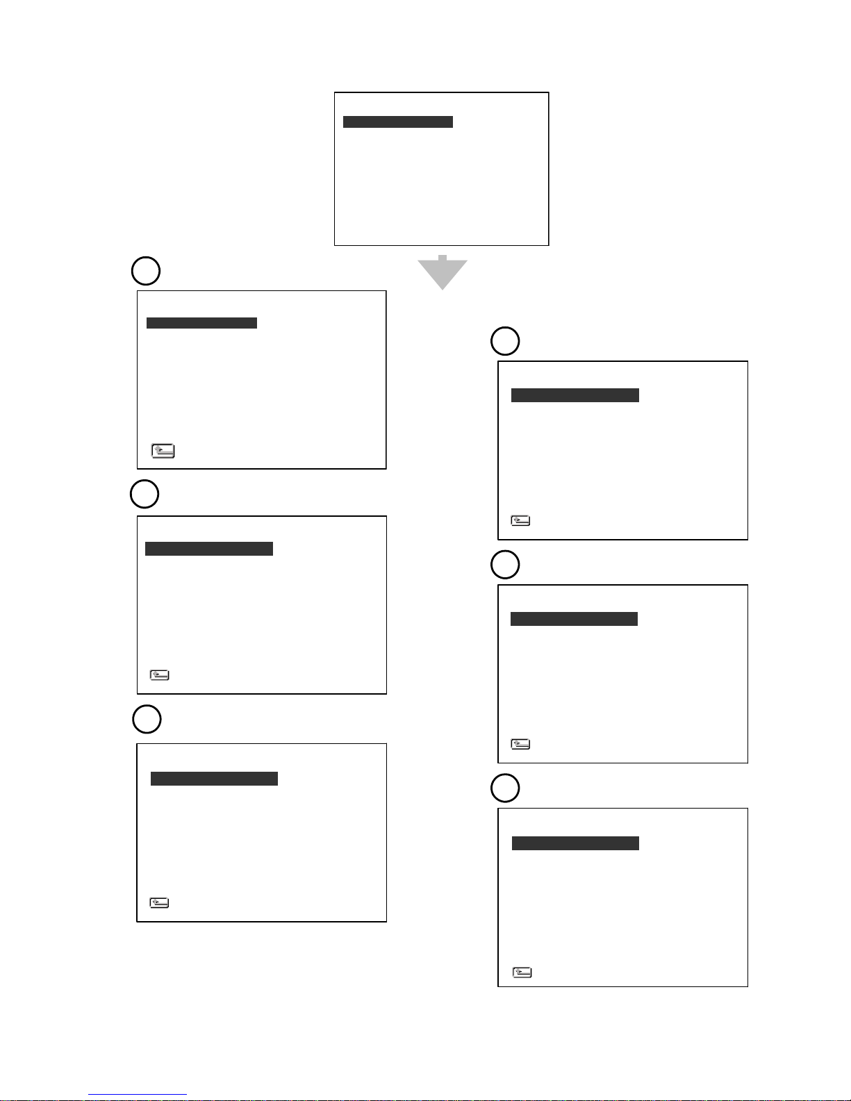
40
1
2
3
4
5
6
AUTO START REC
REC RATE
REC QUALITY
DISK FULL
AUDIO
POST-REC DURATION
SPLIT
A/V SOURCE
REC SETTING
MAIN PAGE
: OFF
: 20 F/S
: BEST
: REWRITE
: OFF
: OFF
: 4CH
: SET
COMM ID
RS232 ENABLE
RS232 CONNECTION
BAUD
COMM SETTING
MAIN PAGE
: 0 1
: ON
: DATA BOX
: 9600
HD REFORMAT
HD FAT32
SD FILE
AUTO ERASE
SD REFORMAT
DISK SETTING
MAIN PAGE
: HD1
: BUILD
: JPEG
: OFF
: START
OPERATION LOG
MENU BACKGND
BUZZER
PAS SWO RD
SETUP PWD
DEFAULT
SD SETUP
VERSION
SYSTEM
MAIN PAGE
: ENTER
: 2
: OFF
: SET
: OFF
: LOAD
: SAVE
: ENTER
RECORD
ALARM
CLOCK/ TITLE
COMMUNICATION
DISK
SYSTEM
MAIN MENU
GOTO REC PAGE
ALM OPERATION
REC RATE
REC QUALITY
AUDIO
ALM TYPE
ALM DURATION
PRE-ALARM
IO CONNECTION
ALARM SETTING
MAIN PAGE
: OFF
: 15 F/S
: BEST
: OFF
: NO
: 30 SEC
: OFF
: ALARM
CLOCK
DAYLIGHT SAVING
TITLE
DELAY ON
DELAY OFF
CLOCK / TITLE
MAIN PAGE
: SET
: OFF
: SET
: OFF
: OFF
5.2 System Default
Page 42
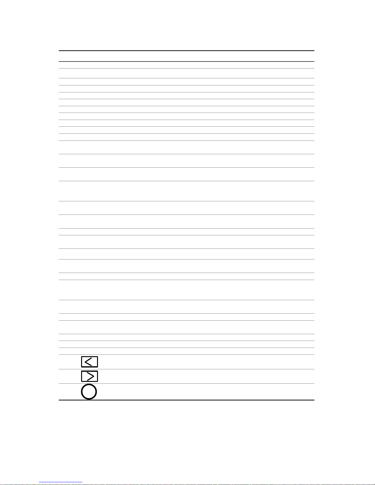
41
5.3 O.S.D Message
No. O.S.D Message Meanings
1 NO DISK
No hard disk detected after power activated
2 BATTERY LOW
Suggest change the battery
3 BATTERY HIGH
Suggest check the battery
4 LOADING
System Boot up
5 VIDEO LOSS
Video loss
6 VIDEO IN
Video input source
7 KEY LOCKED
Key lock function is on
8 KEY UNLOCKED
Key lock function is off
9 n1 OF n2 ITEMS PROGRESS n3 %
BACKUP n1/n2 NOW
10 BACKUP COMPLETE
Backup complete
11 NO ENTRY FOR BACKUP
No backup is possible.
12 BACKUP INCOMPLETE
Backup incomplete, since the user has pressed
the STOP button to stop it
13 NOT FOUND
The system cannot find a video in the Search
function.
14 END
Playback of recorded video has reached the end
point
15 DISK FULL
Hard disks are full; this happens only when the
DISK FULL item in the setup menu is set to
STOP.
16 EMPTY
The user presses the PLAY button or uses the
Search function, but no video can be played.
17 SET TO NTSC, PLS RESTART
System has to be set to NTSC, please reboot
(PAL is similar)
18 SOFTWARE UPDATE
Software update
19 PLEASE RESTART
The system should be rebooted after the softwa re
has been updated
20 NO DISK
There is no disk.
21 SD CARD ERROR
The user has pressed the Save key without
putting in an SD card.
22 FAN STOPPED
The chassis fan has stopped for over 30 seconds.
23 HDn ERROR AT xxxxx
There is a hard-disk error during recording, where
n is the hard-disk number and xxxxx is the
hexadecimal location.
24 NOT PRESENT
When the user tries to clear a disk that was not
attached in the setup menu.
25 SAVE MXXXX.AVI TO SD CARD
Start saving t o the AVI file.
26 SAVE TO Fnnnn. JPG
Start saving to the JPEG file. (where nnnn=
0…9999)
27 SAVE OK
Saving to the JEPG or AVI is ok.
28 SD CARD WRITE PROTECT
An SD card is write-protected; or there is an error.
29 ACC OFF
Power off.
30
Received the leftside trigger signals.
31
Received the rightside trigger signals.
32
S
Received the brake triggering signal.
Page 43
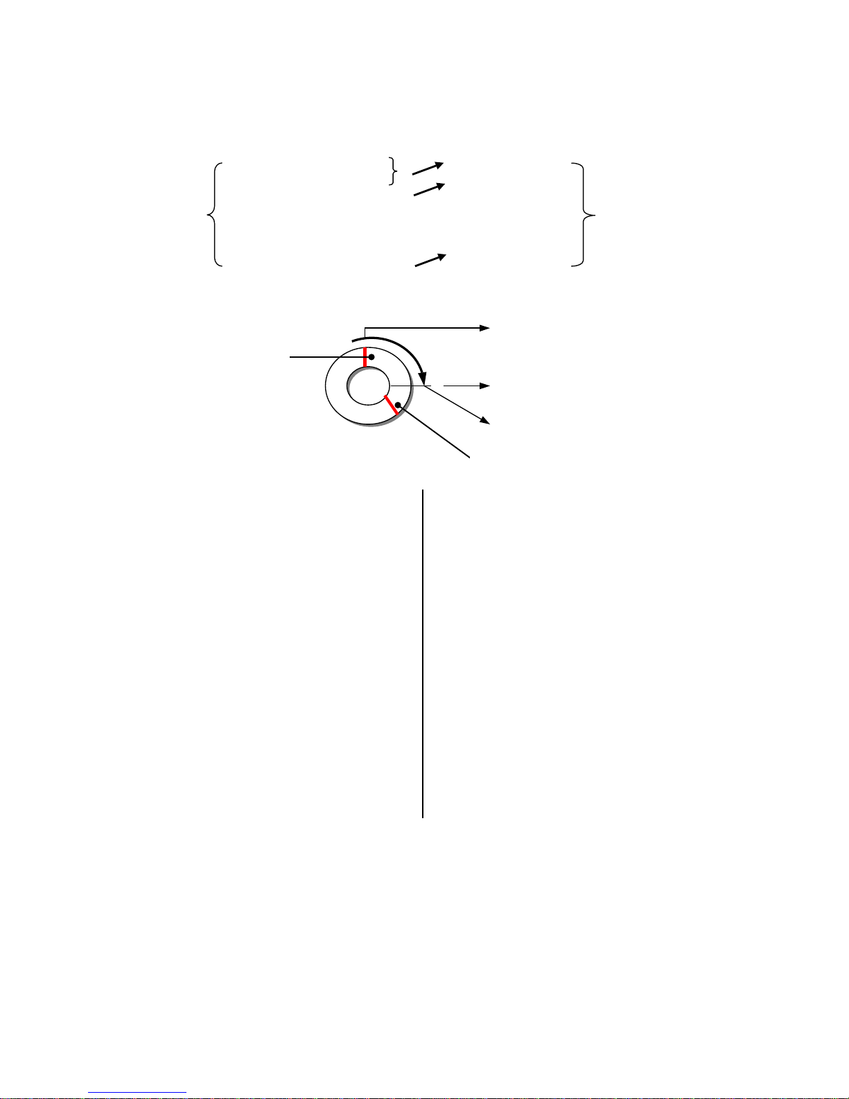
42
5.4 Time Index Table
HD1
HD1
1 12-02-03 12:20:55
1
12-02-03 12:20:55
2 12-02-03 13:30:33
2
01-30-04 16:00:34
3 01-30-04 16:00:34
:
:
:
:
:
:
2999
02-03-04 16:00:56
3000
Indexes
3000 02-03-04 16:00:56
3000
02-08-04 17:30:58
3000
Indexes
The DVR will generate a Time Index Table
indicating recorded data is kept in a particular
HDD. This allows individually selected recorded
data to be displayed via the alarm list search
and full list search. The maximum number of
lists, for a given HDD is
3000. When the list of
any given HDD is used up and the disk is not full,
the unit will still use the rest of the space for
recording. In such a case, an index for the
recent recorded data will be generated and the
index of the next oldest data will be erased so
that the list remains 3000 in total. And the next
oldest data will be kept in the index of the
corresponding oldest data. For any
newly-recorded data, this approach will be
applied until the disk becomes full.
In the rewrite recording mode, when the
archived hard disk drive is full, the DVR will start
overwriting the oldest data recorded. As the
previous recorded data was partially overwritten
by the recent recording, the indicating time index
of that data will be changed corresponding to the
starting time of the remaining session. The index
of the session will be deleted from the table
when it is fully overwritten.
Previously
recorded data
overwritten
The point at which recording stops
Previously recorded data remaining
Page 44

43
5.5 Specifications
Image System
NTSC PAL
Resolution
720x480 pixels 720x576 pixels
Video In
(DIN) x 4 ---(With 12VCC & GND)
Video Out
Monitor Out (RCA x 1)
Audio in/out
Line in (RCA x 2) / out (RCA x 1), 11kHz/22kHz
Operation Mode
Play or Record
Compression
MJPEG
Storage Media
>160GB Micro-Driver x 1 (2.5”)
Memory Card
SD Card
Watermark
Digital Signature
Window Division
1 / 2 / 3 / 4
Recording Rate(Frame)
30 FPS/CH 25 FPS/CH
Display Rate
30 FPS/CH 25 FPS/CH
Picture Quality
Best(64KB)/High(32KB)/Standard(21KB)/Basic(16KB)
Recording Mode
Manual / Alarm
Recording List
3000 Records
Alarm Record
Pre-alarm / Post alarm
Pre-alarm Record
50 images
Playback Speeds
Frame Stepping, 1X, 2X, 4X, 8X, 16X, 30X, 100X,
1/2X, 1/4X, 1/8X, 1/16X
Record Search
Time & Date/ Full list/ Alarm list/ Filter (thumbnail)
Set-up Menu
Multi-layer
Log List
2000 Records
GPIO
Input x 4; Output x 2
Wired Remote Controller
Yes (Length: 3M)
Vibration
1.25G (Random) / 0.8G (Sine)
Mechanical Shock
8G
Built-in buzzer
Yes
Communication Port
RS-232
USB
B-Type, Slave mode
GPS Supported
Yes
Software Upgrade
Upgrades via Memory Card (SD)
Password Protection
Operation /Menu Setup
Operation Power
DC 12V
Power Consumption
DC 11~14.5 V
Delay-off
Yes (Max. 30A)
Dimensions
178 x 173 x 50 mm
Standard HDD: 0 – 45℃ (32 –113℉)
Operation Temperature
Industrial HDD: 0 – 60℃ (32 –140℉)
Certificate
FCC, CE, E/e-mark, RoHS
Note: The maximum electric current provided for 4 mobile cameras is 1 ampere ( 1A ) in total.
Note: Design and specifications are subject to change without notice.
Page 45
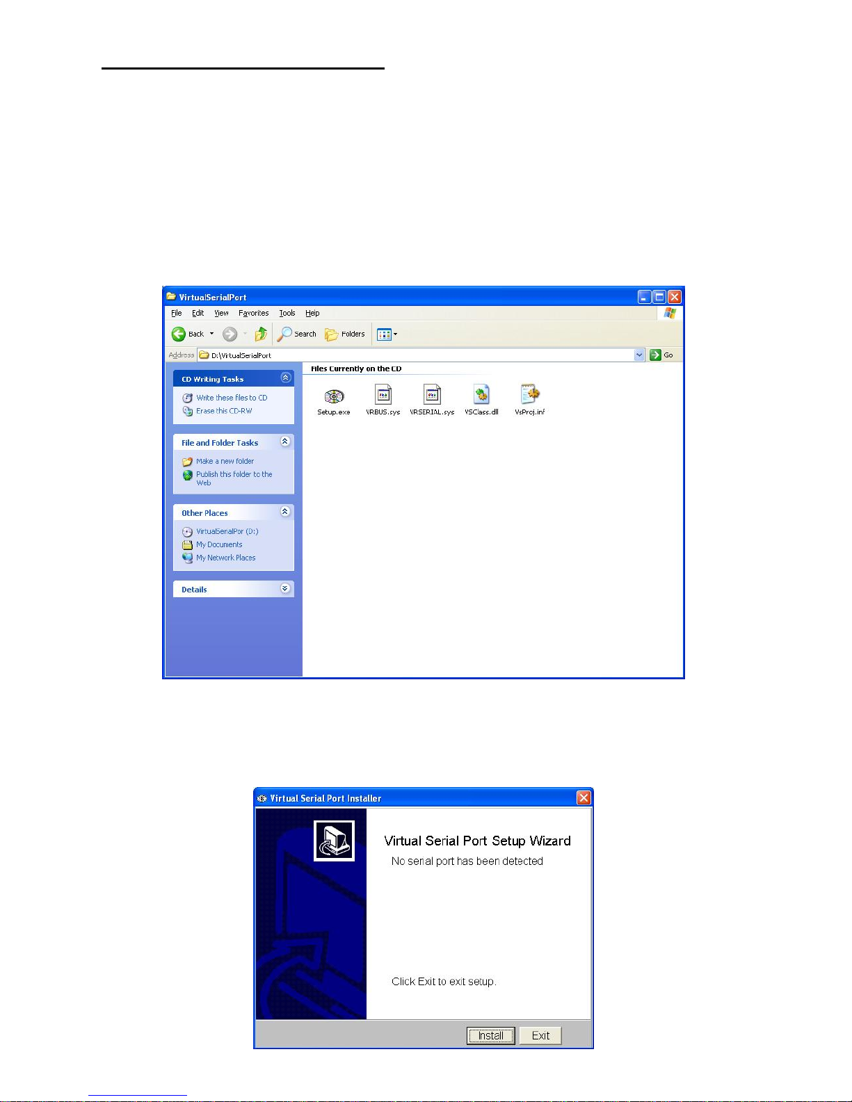
44
APPENDIX 1. –Virtual Serial Port
1. Connection Application Software Installation.
You can use your personal PC with HDD Viewer to connect to the PaPaGo Electronic
Mapping to monitor your geographic location and the surrounding public facilities. Please
follow the steps below to install the software application.
Insert the CD that came with the HDD Viewer into your CD-ROM drive.
Click the “My Computer” icon, select your CD-ROM drive, go to the “VirtualSerialPort”
folder, and double click the “Setup.exe” file to start up the installation process.
The windows screen below will appear on your screen. Click Install and installation will
begin right away.
Page 46
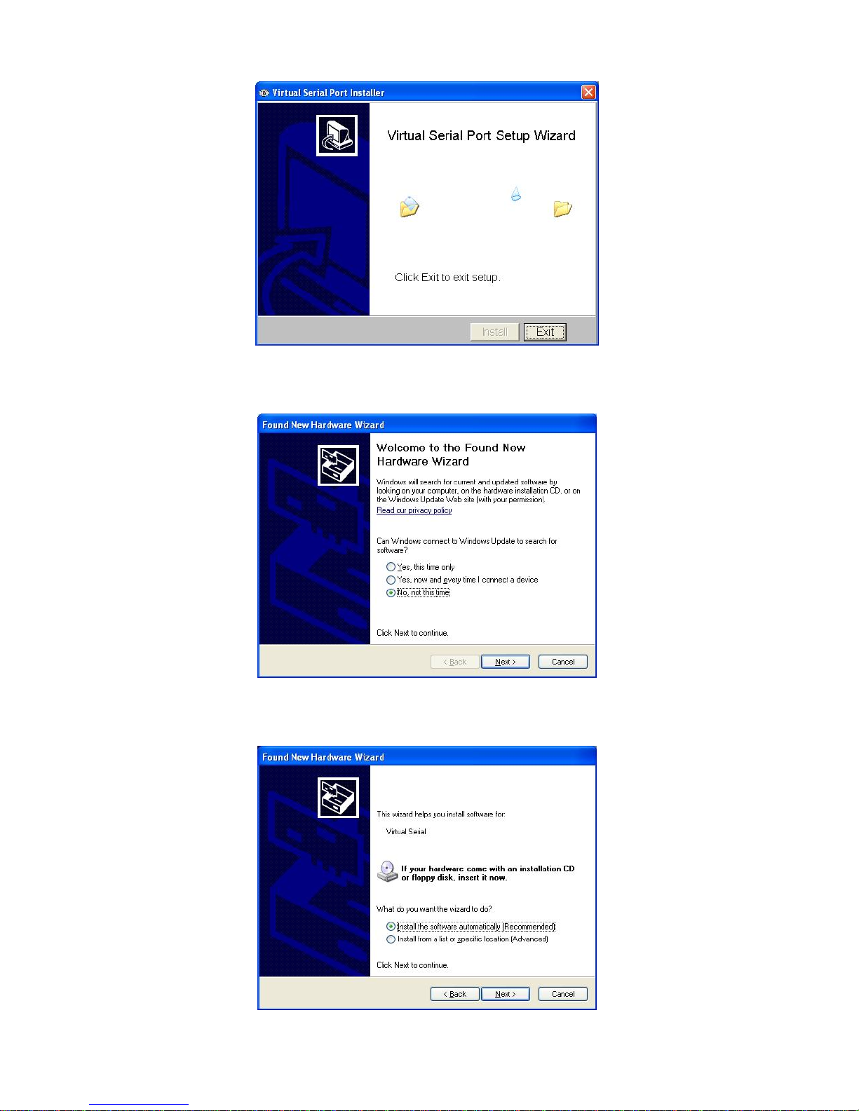
45
Performing the setup functions:
Please choose “No, Not This Time,” and click the ”Next” button.
Choose “Install the software automatically (Recommended),” and click the “Next” button.
Page 47
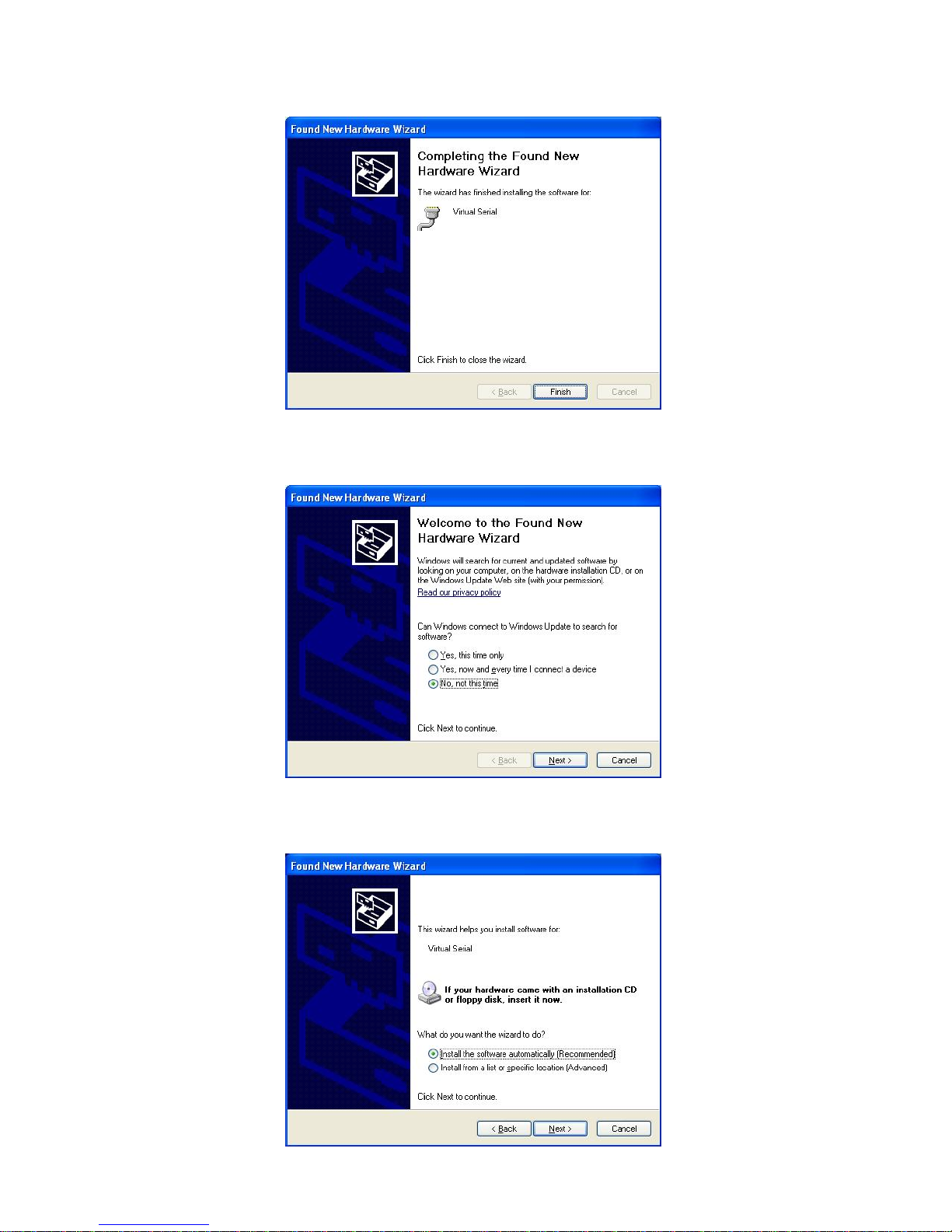
46
The new hardware installation is complete; now please click the “Finish” button. Wait a few
moments and a message will pop up on the screen.
Again, please choose “No, Not This Time,” and click the ”Next” button.
Choose “Install the software automatically (Recommended),” and click the “Next” button.
Page 48
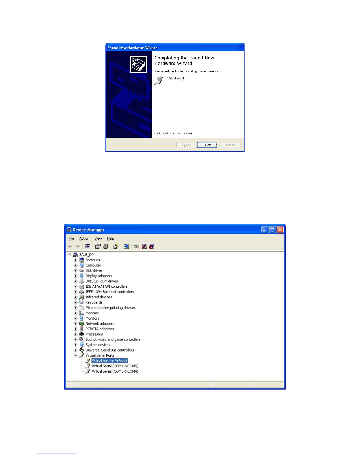
47
The new hardware installation is complete; now please click the “Finish” button. Wait a few
moments and a message will pop up on the screen.
Go to the “Device Manager” to make sure the driver is installed.
Right click on the “My Computer” icon, select “Properties” click the “Hardware” tab, and then
click the “Device Manager”.
Now, “Virtual Serial Ports” will appear as a new category. Click the “+” sign to expand “Virtual
bus for VrSerial”.
Page 49
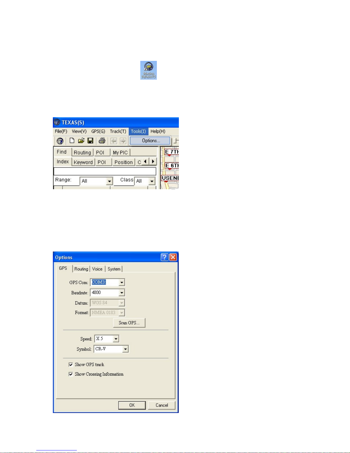
48
2. The PaPaGo Electronic Mapping Setting.
Please follow the instructions on the PaPaGo installation CD perform setup. Once
done, you can click PaPaGo on the desktop to operate.
Under the “Tools” tab, select “Options”.
Click the “GPS” tab, and use the drop down menu to select any available com port ;
in our example we use com 3.
(You can choose your own Baudrate, as long as the Baudrate on two com ports
are the same. In our example, we have set it at 4800)
Page 50
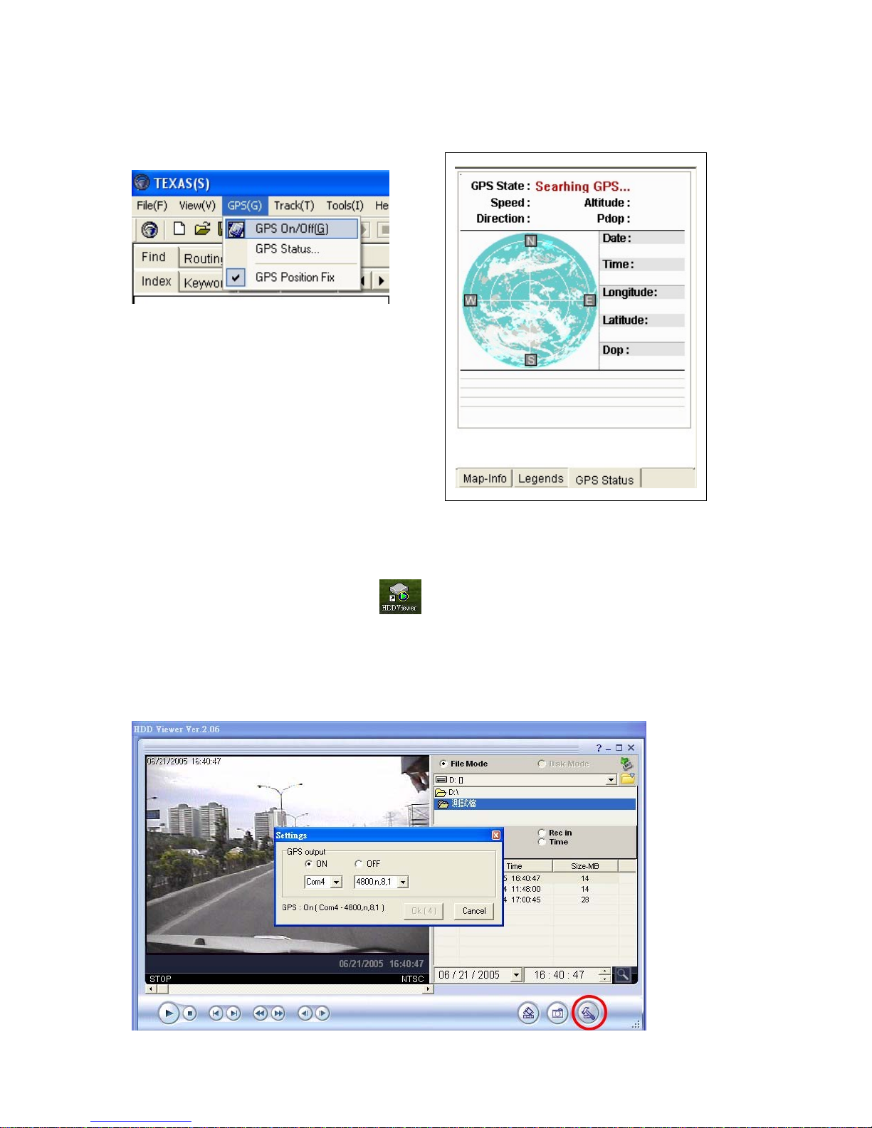
49
On the “GPS” tab, choose “GPS Status,” and you will see a message which is
searching for the GPS installation on the lower right corner of your screen. Now the
PaPaGo setup is complete, and you can open the HDD Viewer.
3. The HDD Viewer Setup.
Double click the HDD Viewer icon on your desktop to start up the application.
Click the red circle button to bring up the “Setting” menu. Choose the other com
port from the drop down menu. Both baudrates on the com ports should match.
Page 51
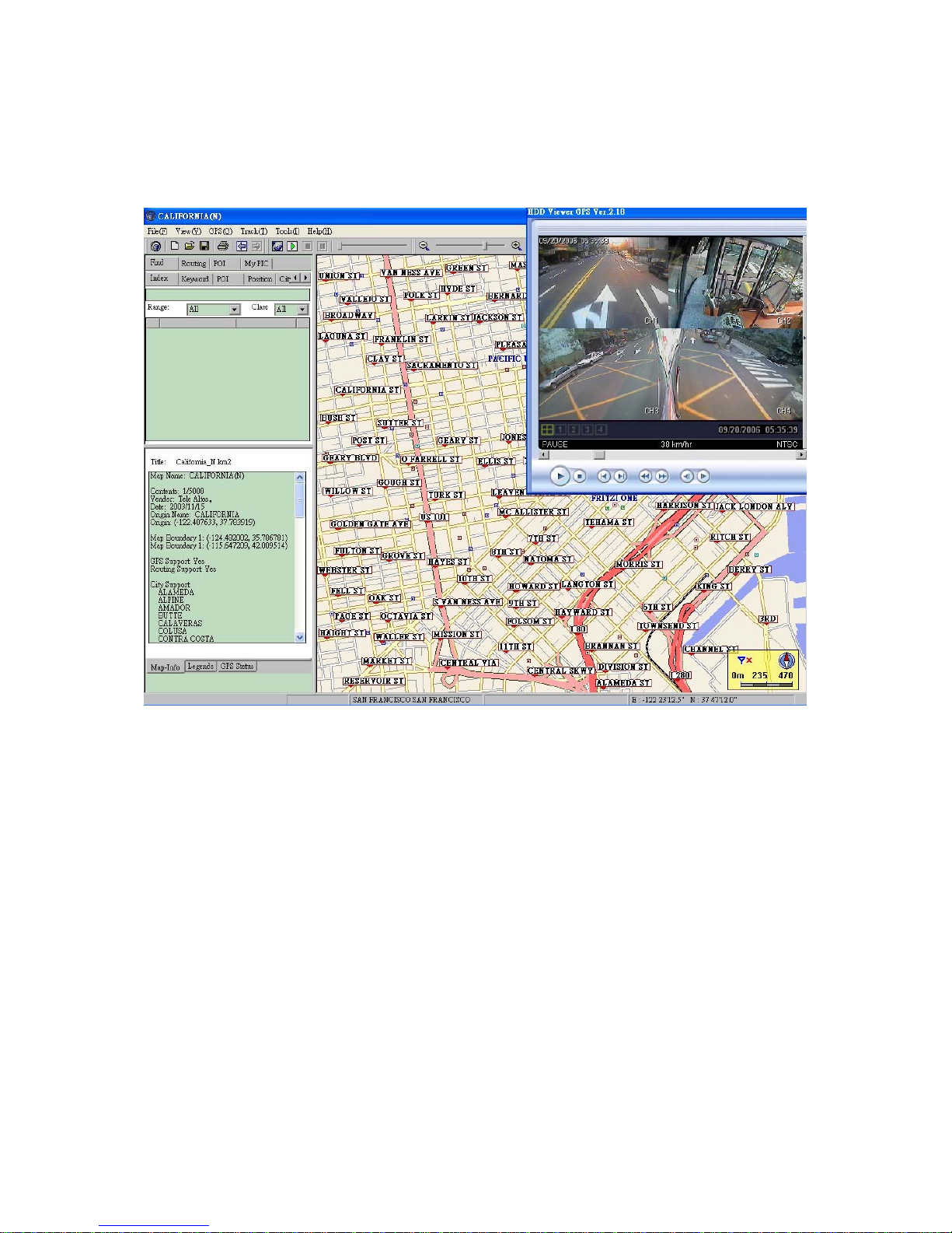
50
4. The Working Screen.
The user can now see both the camera screen and the electronic map on the PC.
Page 52

51
APPENDIX 2. – FAQ
1. How to choose a channel in the play mode?
ANS: If you want to choose a channel in the play mode, press the SEARCH button
to enter the "SEARCH" menu. Next choose "FULL LIST" and push the Enter
button to enter the record list page. Use the Up and Down buttons to select
the record you want. Then press the Enter button again to enter the quad
mode screen. Now press the channel buttons to let your desired channels be
displayed on the full screen.
Note: The channel - access buttons are the Up and Down, and Left and Right,
buttons.
Note: If you want to leave the play mode, click the "Stop" button to exit the
play mode for the live mode.
2. How to use the audio functions in the play mode in the camera channels?
ANS: When you press the "PLAY" button to enter the play mode, you then press
the SEARCH button to change the two audio sources to any one or two of the
four cameras you have. The audio types are of three kinds: Audio 1, Audio 2,
and Audio 1 + 2, accessible in this order with each successive sequential
click. You can set up Audio 1 and Audio 2 in separate channels. Press the
SEARCH button once to hear the audio in any one channel. Press "SEARCH"
again to hear the audio in another channel, the two audios playing together. If
you press the SEARCH button again, you can play Audio 1 and Audio 2
together in any one single channel. The sound is better if you play both Audio
1 and Audio 2 in one channel.
Page 53
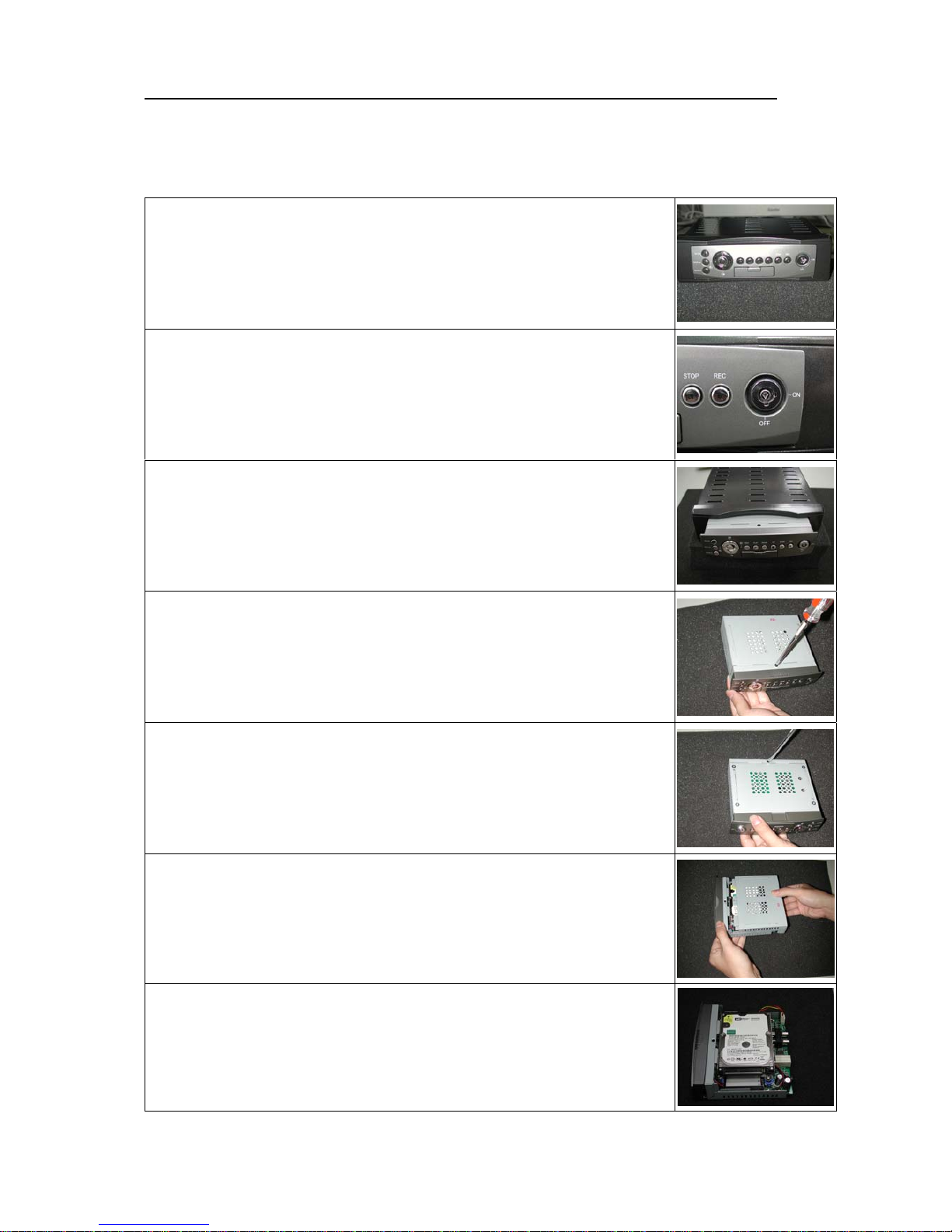
52
APPENDIX 3. – Changing the built-in hard disk of the mobile DVR
This is a manual for assembling the component parts of the mobile DVR unit.
Please follow the steps detailed here in order to complete the procedure.
Step 6.
Detach the lid of the unit.
Step 7.
The hard disk inside the unit is exposed.
Step 1.
Here is a mobile DVR, with the recording unit sitting inside the
host casing.
Step 2.
Use your key to unlock the lock on the front panel of the
recording unit, turning the arrowhead in the lock to point from
"ON" to "OFF".
Step 3.
Pull out the recording unit from inside the casing.
Step 4.
Unscrew the screw atop the recording unit.
Step 5.
Unscrew the screw below the unit.
Page 54
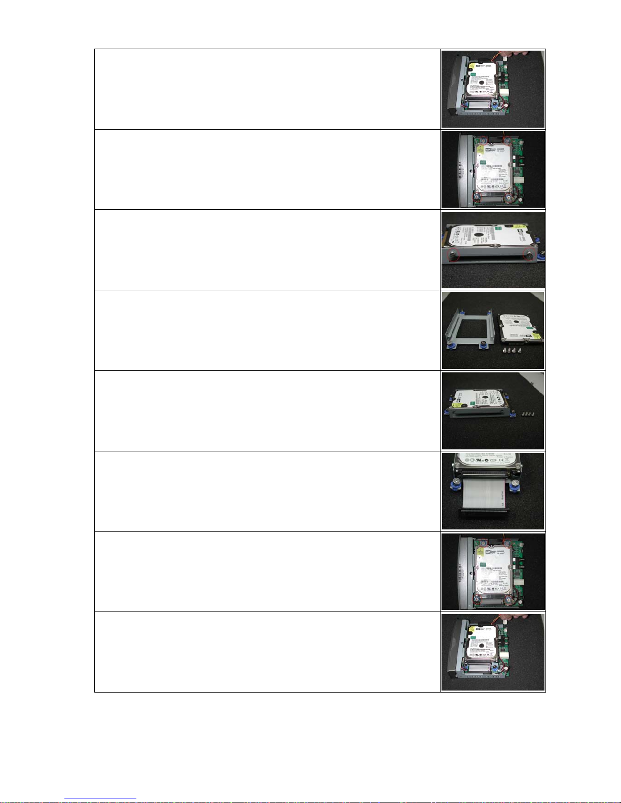
53
Step 8.
Detach the fan connector from the board.
Step 9.
Unscrew the 4 screws of the main board of the unit.
Step 10.
Take out the hard disk and the hard disk rack after you pull out the
cable connector. Unscrew the 4 screws of the rack, and pull out the
hard disk.
Step 11.
Get your new hard disk.
Step 12.
Screw in the 4 screws of the hard disk to fix it to its rack.
Step 13.
Connect the cable. Take care the cable's red lining is on the
right-hand side as you attach it.
Step 14.
Put the rack back on the main board and screw in the board's 4
screws.
Step 15.
Attach the fan connector to the cable's right.
Page 55
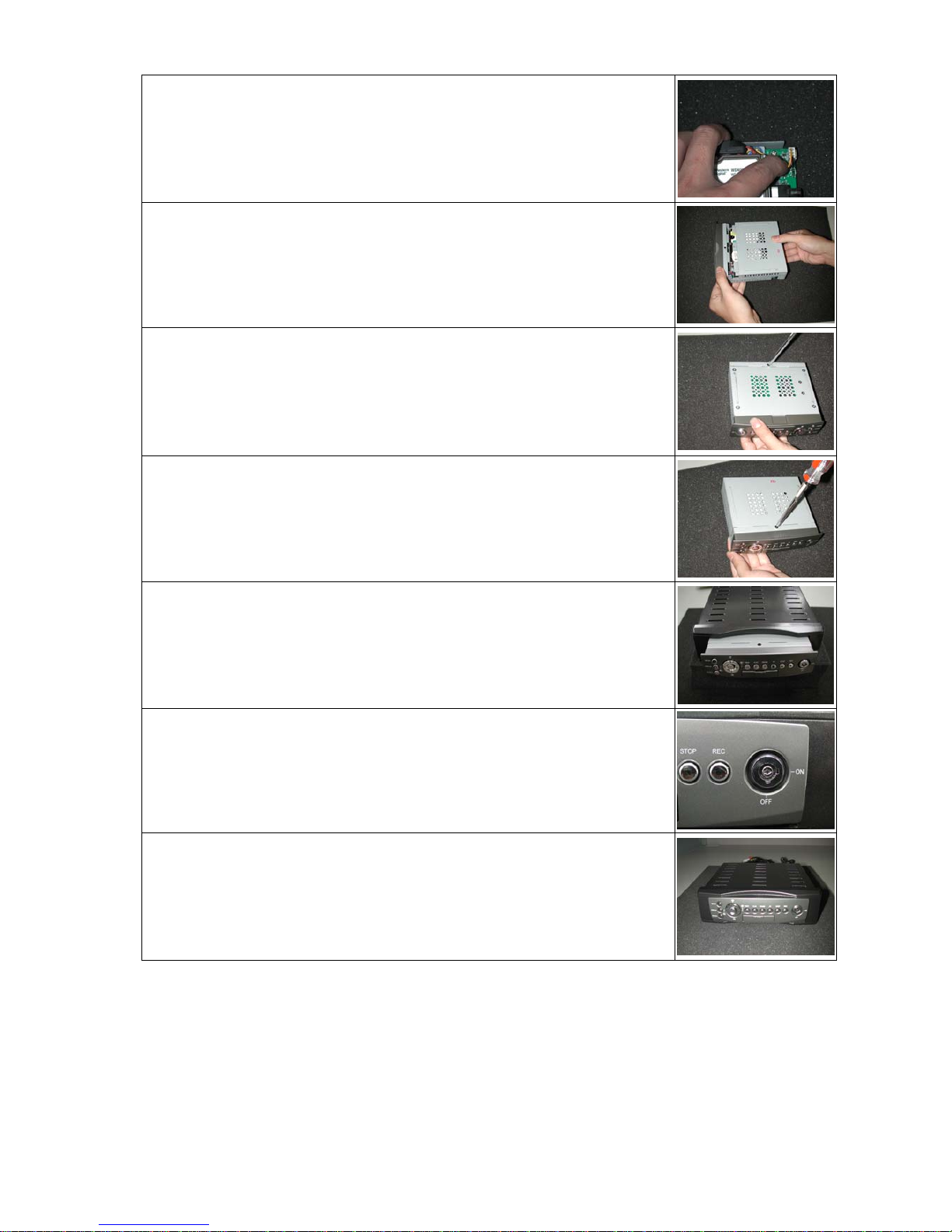
54
Step 16.
Take care the fan connector cable is not outside the recording
unit case, as otherwise it might be broken when the unit's lid is
reattached.
Step 17.
Reattach the lid.
Step 18.
Screw in the screw below the recording unit.
Step 19.
Screw in the screw atop the recording unit.
Step 20.
Place the recording unit inside the host casing.
Step 21.
Use the key to turn the arrowhead inside the lock to "ON".
Step 22.
The procedure is complete.
 Loading...