

Page 1
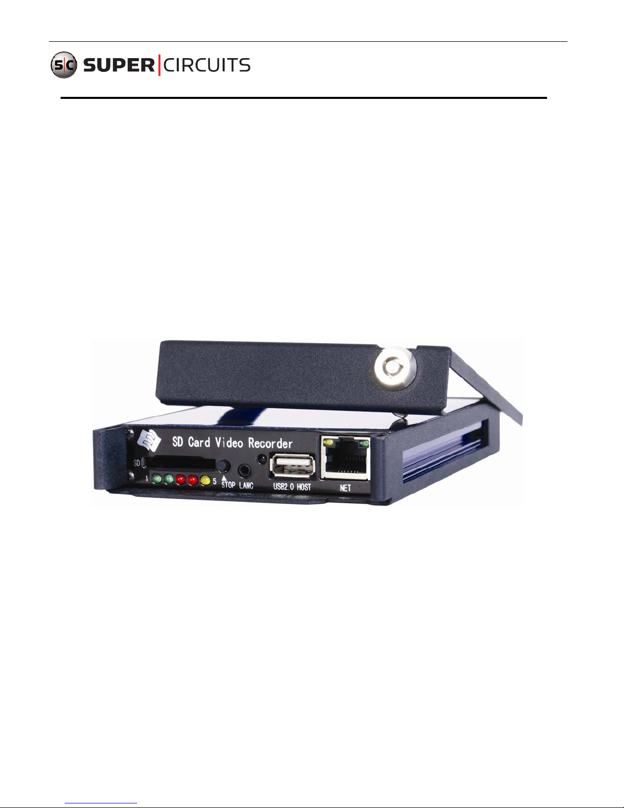
MDVR21SD
Advanced Solid State Mobile DVR
User Manual
Thank you for using our video recorder. This manual is applicable for 1ch, 2ch and 4ch SD Video Recorder. Please
read this User’s Manual carefully to ensure that you can use the device correctly and safely. The contents of this
manual are subject to be changed without notice.
www.supercircuits.com MDVR21SD_RM
1
Page 2
Warning
This device is NOT of waterproof; to prevent it from any accident of fire or
electric shock, please do NOT put any container with water on the device or
nearby. Do not expose the device to moisture, or extreme temperatures.
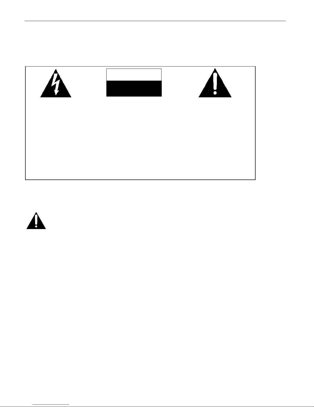
This lightning flash with
arrow symbol within an
equilateral triangle is
intended to alert users
that there might be
uninsulated dangerous
voltage which may cause
To prevent from the risk of
electric shock, do NOT
remove top cover or back
cover. There is NO
user-serviceable part
inside. Ask for service from
qualified maintenance man.
CAUTION
RISK OF ELECTRIC SHOCK
DO NOT OPEN
The exclamation point within
an equilateral triangle is
intended to alert users the
important operating and
maintenance(servicing)
instructions in this manual.
Important notice:
1. Please read over all cautions.
2. Please keep this manual for reference in the future.
3. Please notice all warning information.
4. Please strictly follow the instructions in this manual while operating.
5. Please NEVER put this device under the place which is easily poured by water.
6. Please do NOT use abrasive chemicals, cleaning solvents or strong detergents to clean the device. Wipe the
device with a soft and dry cloth.
7. Please do NOT get the gate of airiness heat exchange closed.
8. Please leave the device far away from hot and high temperature environment.
9. Install the device with the accessories coming with it.
10. Please take care when moving the device, make sure of security, and avoid being damaged by dropping from
high place.
11. Call for qualified maintenance man to repair when needed.
12. The device can only be installed horizontally. Installed vertically or out of the horizontal could hurt person or
damage the device or/and its parts.
www.supercircuits.com MDVR21SD_RM
2
Page 3

TABLE OF CONTENTS
MDVR21SD ADVANCED SOLID STATE MOBILE DVR.................................1
1.GENERALINTRODUCTION....................................................................................5
2.PRODUCTFIGURES...............................................................................................7
2.1FRONTPANEL.........................................................................................................................................................................7
2.2REARPAN EL............................................................................................................................................................................8
2.3WIRELESSREMOTECONTROLLER................................................................................................................................................9
3.INITIALSETUP......................................................................................................9
3.1TAMPER‐PROOFCASEMOUNTING..............................................................................................................................................9
3.2POWERCONNECTION.............................................................................................................................................................11
3.2.1.UseIgnitionSwitchtoTurnOn/OffDVRSystem.......................................................................................................11
3.2.2,TurnOn/OffDVRSystemAutomatically..................................................................................................................11
3.3CAMERACONNECTION...........................................................................................................................................................12
3.4SENSORHARNESSCONNECTION...............................................................................................................................................14
GPSConnection(Option)....................................................................................................................................................14
3.5EVENTBUTTONANDCABLECONNECTION(OPTION)....................................................................................................................15
4.MAINSYSTEMOVERVIEW..................................................................................16
5.BASICOPERATIONANDMENUSYSTEM..............................................................17
5.1SDCARDFORMATTING...........................................................................................................................................................17
5.2CHOOSERECORDINGMODE....................................................................................................................................................18
5.3FILELENGTH.........................................................................................................................................................................19
5.4RECORDINGQUALITY..............................................................................................................................................................19
5.5STAR TRECORDING.................................................................................................................................................................21
5.6PLAYBACKOPTION.................................................................................................................................................................22
5.6.1PlaybackfilesonDVRsystem....................................................................................................................................22
5.6.2Playbackthefilesonmanufacturer’sPCPlaybackSoftware.....................................................................................25
5.7,FILEBACKUP........................................................................................................................................................................25
5.8ALARMRECORDING...............................................................................................................................................................25
5.8.1SetupTheAlarmAction.............................................................................................................................................25
5.8.2PostEventRecord......................................................................................................................................................27
5.9MOTIONDETECTION..............................................................................................................................................................28
5.9.1SetMotionDetectionZone........................................................................................................................................28
5.9.2SetMotionDetectionAction.....................................................................................................................................28
www.supercircuits.com MDVR21SD_RM
3
Page 4

5.9.3SetMotionSensitivity................................................................................................................................................29
6.0VIDEOLOSTALARM...............................................................................................................................................................30
6.1SCHEDULERECORDING...........................................................................................................................................................30
6.2VIDEOSYSTEMSETTING..........................................................................................................................................................31
6.3SETDATE ANDTIME...............................................................................................................................................................32
6.3.1SetDateDisplayFormat............................................................................................................................................32
6.3.2SetTheTimeZone.....................................................................................................................................................32
6.3.3SetDateandTime.....................................................................................................................................................32
6.4CONFIGURATIONSETUP..........................................................................................................................................................33
6.5USERLEVELANDPASSWORDSETTING........................................................................................................................................34
6.6NETWORKSETTING............................................................................................................................... .................................35
6.7MOTOR.............................................................................................................................................................................36
6.7.1Set“LICENSEID”and“LINE”......................................................................................................................................36
6.7.2GetSpeedfromGPS..................................................................................................................................................37
6.7.3GetSpeedfromSpeedometer....................................................................................................................................39
6.8MANAGETHEPOWER.............................................................................................................................................................41
6.8.1,Useignitionswitchtoturnon/offtheDVRsystem...................................................................................................41
6.8.2,TurnOn/OffDVRSystemAutomatically..................................................................................................................42
6.9USEPTZ..............................................................................................................................................................................43
6.9.1PTZControl................................................................................................................................................................43
6.9.2Renamethecamera..................................................................................................................................................44
6.9.3VideoAdjustment......................................................................................................................................................44
6.10GPSSETTING(OPTION)........................................................................................................................................................45
6.11EVENTBUTTON&CABLESETTING(OPTION)............................................................................................................................45
6.12FIRMWAREUPDATE..............................................................................................................................................................48
6.13USINGWI‐FIMODULE(OPTION)...........................................................................................................................................49
7.CONNECTION&INSTALLATIONCABLES..............................................................53
7.1POWERSUPPLYCABLE............................................................................................................................................................53
7.2VIDEO&AUDIOINPUT/OUTPUTCABLE............................................................................................................................... ....54
7.3SENSORHARNESS..................................................................................................................................................................55
8.SPECIFICATION...................................................................................................57
9.LISTOFSTANDARDACCESSORIES.......................................................................58
10.TROUBLESHOOTING........................................................................................59
www.supercircuits.com MDVR21SD_RM
4
Page 5

1. General Introduction
The MDVR21SD series mobile digital video recorder is a compact, f ull-featured record ing system that uses a SD card
as a storage device. The recorder unit and associated accessori es are specifically designed for operation in a mobile
environment.
The MDVR21SD system, used in conjunction with the camer as, record s up to four channel s of full-motion v ideo and
audio data to a Class 4 (minimum) SD card. The firmware-driven menu system provides a simple method for
configuring the unit’s operation as well as searching for and viewing previously record ed AV records.
Regulatory Compliance
The MDVR21SD complies with CE and Part 15 of the FCC interference limits for Class B digital devices FOR HOME OR
OFFICE USE. These limits are designed to provide reasonable protection against harmful interfer ence. Operation of this
device is subject to the following conditions: (1) This device may not cause harmful interfer ence, and (2) this device
must accept any interference received, including interference that may cause undesired operation.
Product Description
The MDVR21SD unit consists of the following major components:
Standard Components and Features
Extruded aluminum case (the case is anodized in cobalt blue).
Front and rear panels.
Mother Board.
Power, AV input and output cables.
Power input 2 amp fuses (2).
Tamper proof and lockable security enclosure.
Panel lock with (2) keys for locking the security enclosure.
Wireless remote controller.
Removable SD card, Class 4, minimum (customer supplied).
Optional Components and Features
GPS speed and location data overlay.
Wired remote cable for non line-of-sight DVR operations.
Extension cable for easy connection and installation.
Product Main Features
Embedded operating system, assuring reliability and system integrity.
Records up to four channels of full-motion color video with corresponding audio tracks.
H.264 High Profile video compression.
Total Record resource up to 100/120 D1 frame/second.
Lockable security enclosure.
Front panel USB2 port for recording to a flash card as an optional storage device.
Ignition sense that provides DVR power-on in recording mode when the bus is started.
Power-off delay record when the bus is shut-down with operator-selected delay times.
www.supercircuits.com MDVR21SD_RM
5
Page 6

Video And Audio
H.264 High Profile video compression, real time recording (25 fps (PAL) / 30 fps (NTSC) f or each channel. Frame
rate adjustable for each channel.
Audio compression: G.711 codec. This codec off ers high compression with high quality audio.
D1 resolution for each channel, which means each channel support 720x576 (PAL)/720x480 (NTSC).
Support 4 channel real time D1 video and 4 channel audio recording.
Local video and audio real time playback.
GPS Time Synchronization & Time Zone
Synchronize the DVR system time with GPS automatically
Support All Time Zones Worldwide
Support DST (Daylight Saving Time)
Power Management
Reliable power management, wide voltage: +8VDC~+40VDC; The power input is protected against short
positive transient (1500 watts peak pulse power capability with a 10x1000 us waveform); The power input is
protected against negative voltage. Applicable for vehicles with +12V or +24V battery.
The recorder provides each camera with stable +12V DC power; DVR can detect the shor t cut on power circuit.
Can use ignition to control the power.
DVR can monitor battery voltage after Ignition off, and auto into sleep mode when voltage is bellow specified
level.
Recording mode
Continuous record.
Support schedule recording.
Support alarm recording.
Support motion detection recording.
Support 2 recording mode, composite mode and separate mode.
Speed and Vehicle status recording
Record vehicle speed and car id with audio and video.
Support 5 sensors, can be connected to speed, ignition, brake, return, right turn, left turn light etc.
Over-speed alarm.
Specified screen can be full screen displayed when return sensor trigged.
SD card plug and play
Support SDHC card within 32GByte.
Support SDXC card more than 64GByte (Maxim 2048GByte)
Support plug and play for SD card when not recording and playing.
Note: If you remove the SD card while recording or playing, it might cause the damage of the file on
SD card. While recording or playing, the yellow light on the front panel will be on. So please stop
recording or playing until the yellow light is off if you need to remove the SD card.
Multiple player supported
You may use manuf actur er’s PC Playback Software or any of the f ollowing third part y media pl ayer to play b ack the
record file.
VLC media player (version1.0.0 or above);
Storm player (Version 2009 or above);
Winamp (Version 5.531 or above).
www.supercircuits.com MDVR21SD_RM
6
Page 7
2. Product Figures
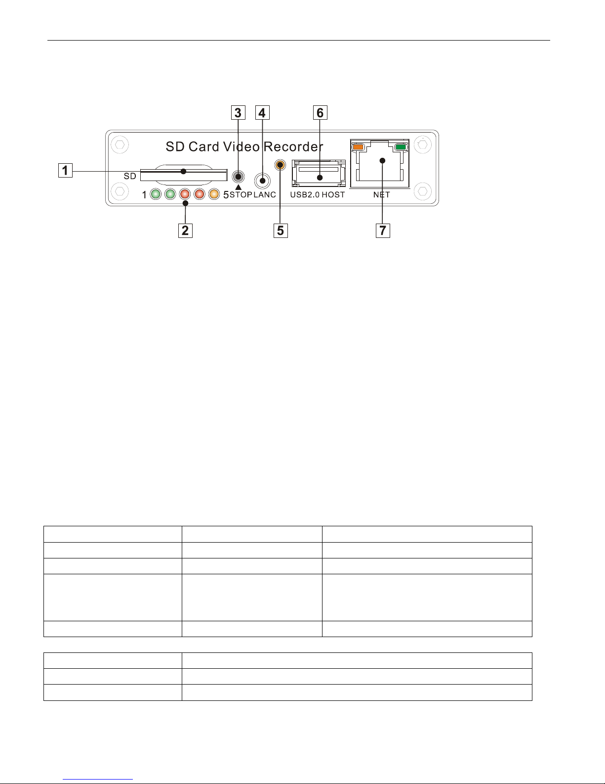
2.1 Front Panel
①:SD Card Slot
②:Status Lights (Power, Run, Alarm, SD Card, Record Status)
③:Stop Button: For stop recording.
④:LANC Port: For connection to an Event Cable or a wired remote IR sensor harness (option )
: Infra-Red receiver window.
⑥:USB Port: Can be used as a secondary recording device, such as a flash memory card. This port cannot be used
as a direct access link to a PC, however.
⑦:Network Port (RJ45).
Get to know the status of DVR system by the indication of LED lights:
1. PWR (Green) 2. RUN (Green) Status/Description
Always On Blinking MDVR21SD is on & running
Blinking with RUN by turns Blinking with PWR by turns Ignition is not enabled and MDVR21SD is OFF.
Blinking together with RUN Blinking together with PWR Ignition sense is not enabled & MDVR21SD is
running. Unit will turn OFF when “Delay Time”
setting is reached.
Blinking every 3 seconds Off Select PWR on the remote control to restart.
3. ALARM (Red) Status/Description
On Alarm input when BEEP is set as “ON”. Audible alarm (beep) when enabled.
Off No alarm.
www.supercircuits.com MDVR21SD_RM
7
Page 8
4. SD (Red) Description
On Writing data to the SD Card.
Off Not writing – inactive.
5. REC (Yellow) Description
On Recording data. CAUTION: Do not attempt to remove the SD card while SYS
mode is active. Select “STOP” on the front panel or remote control to stop
recording.
Off Not recording.
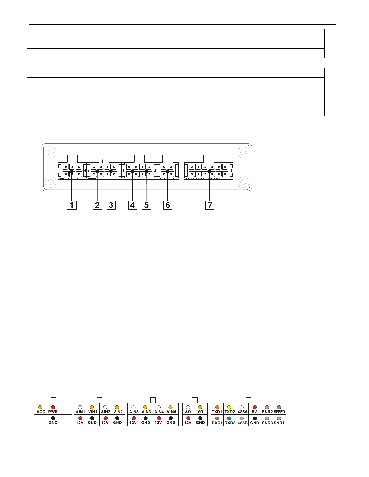
2.2 Rear panel
①:Power, Ground and ACC input.
②:AV input 1(including audio input 1, video input 1 and power output for camera 1)
③:AV input 2(including audio input 1, video input 1 and power output for camera 2)
④:AV input 3(including audio input 1, video input 1 and power output for camera 3)
⑤:AV input 4(including audio input 1, video input 1 and power output for camera 4)
⑥:AV output (including audio output, video output and power output)
⑦:1x speed sensor, 3x sensors inputs, 2x RS232 port, 1x RS485 port and 1x 5V DC output.
The sockets on rear panel are of Molex Micro-Fit 3.0 (Model No.: Molex 0430450200). The
definition of all sockets are given as below:
www.supercircuits.com MDVR21SD_RM
8
Page 9
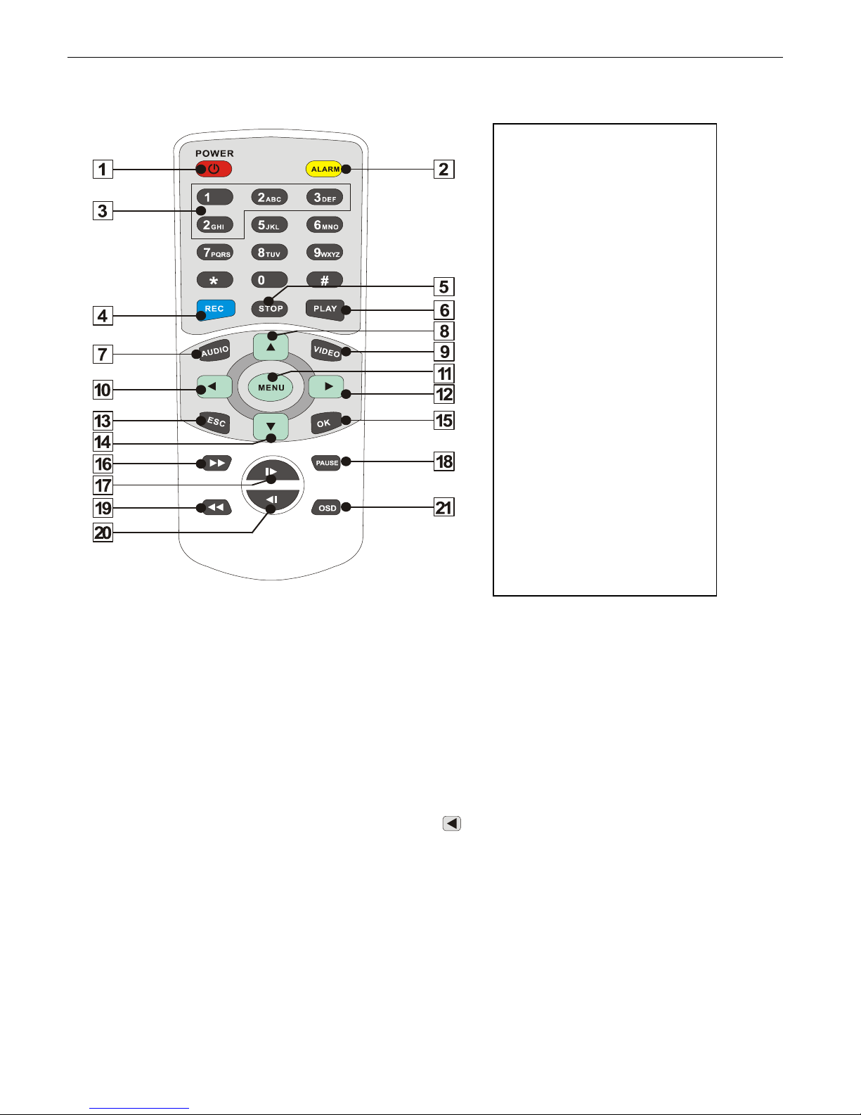
2.3 Wireless Remote Controller
1. Power
2. Alarm
3. Digits
4. Record
5. Stop
6. Play
7. Audio Toggle
8. Up
9. Video Toggle
10. Left/Backspace
11. Menu/Enter
12. Right
13. ESC
14. Down
15. OK to confirm
16. Fast Forward
17. Next
18. Pause/Step
19. Fast Backward
20. Previous
21. OSD
How to use the remote:
1) Press
<MENU> to enter DVR system menu or sub menu. You can also use <MENU> to select among
different value in the submenu. You can also use
<MENU> as <OK>;
2) Press <UP/DOWN/LEFT/RIGHT> button to move between the different menu item;
3) Press <OK> to save and exit the current menu. Press <ESC> to cancel and exit the current men u. If you modify
something in the menu, recorder will prompt a window to ask you to save or cancel your modification;
4) Press <VIDEO> to toggle among different video channel;
5) Press <AUDIO> to toggle among different audio channel;
6) To delete character in the edit control, you can press <
>;
7) Press <POWER> for a while to turn on/off the recorder.
3. Initial Set Up
3.1 Tamper-proof Case Mounting
1) Use a power drill and screws supplied to fix the bottom cover of the tamper-proof case in the right place inside
the vehicle.
www.supercircuits.com MDVR21SD_RM
9
Page 10
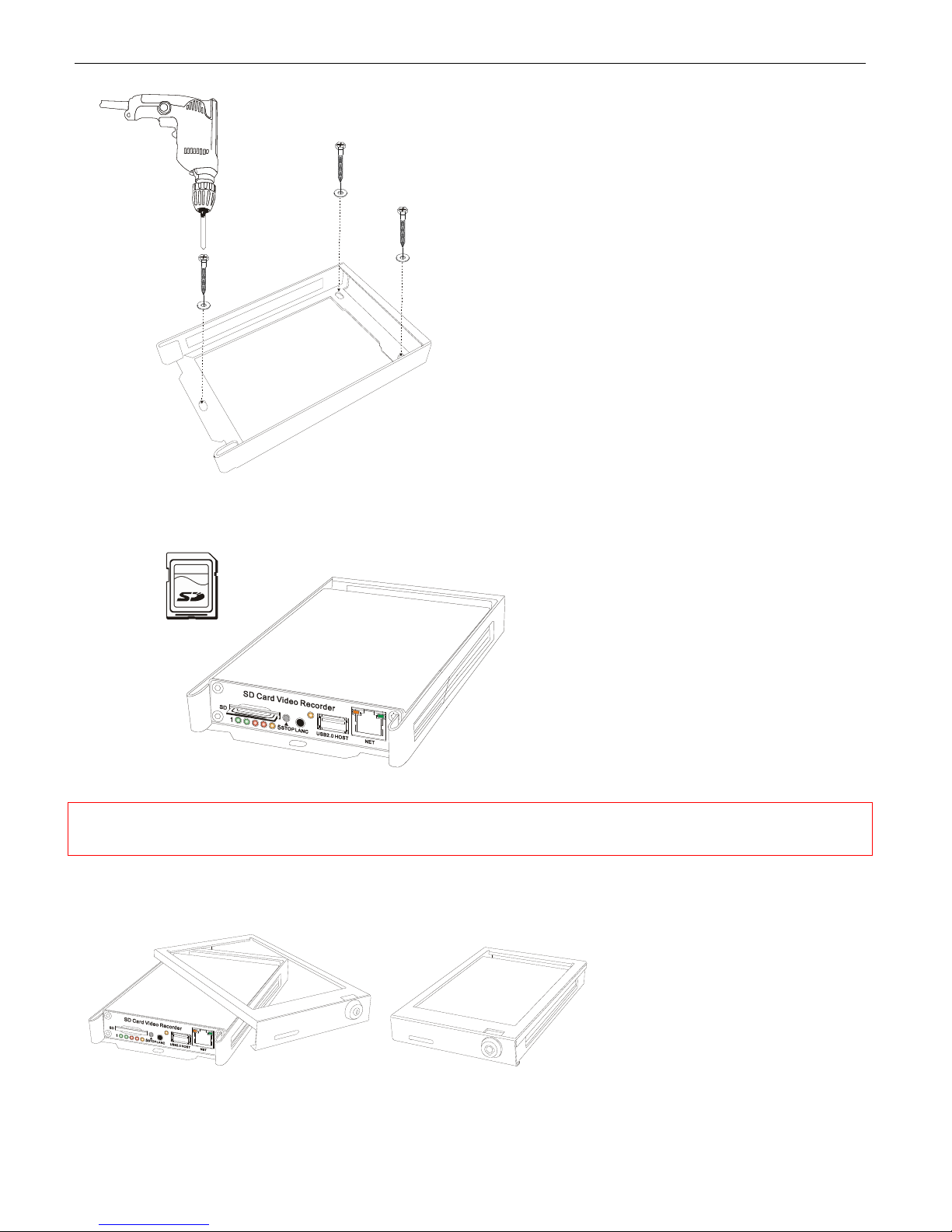
2) Put the DVR system inside the bottom cover, and load a SD Card.
NOTE: The lock jumper of SD Card should be in OFF position. Kingston Class 4 or above, Transcend
Class 6 or above is recommended for fast write speed.
3) Close with the top cover and lock it with keys supplied.
www.supercircuits.com MDVR21SD_RM
10
Page 11
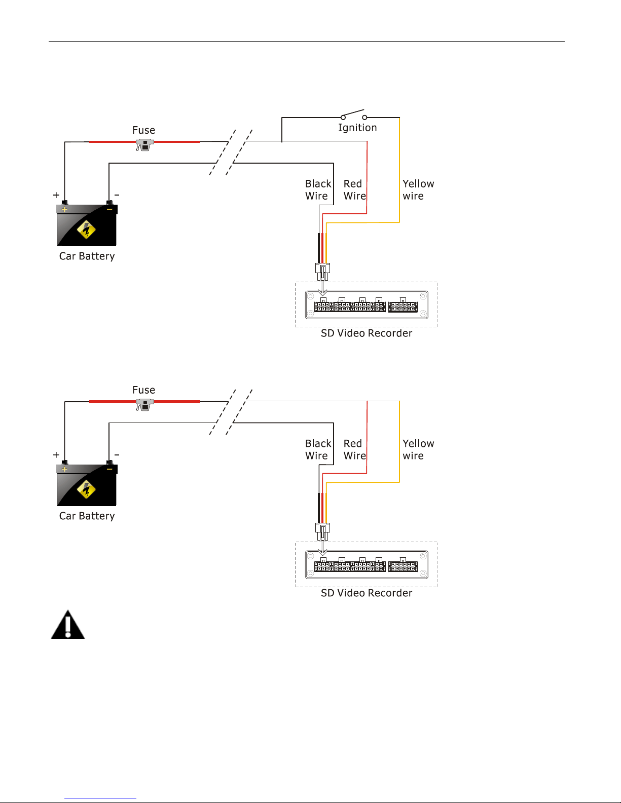
3.2 Power Connection
3.2.1. Use Ignition Switch to Turn On/Off DVR System
3.2.2, Turn On / Off DVR System Automatically
NOTE
1. The DVR uses DC power input, please be very careful when connecting to the “+” and “-” of the power supply.
2. Wide voltage range of 8V-32V for the DVR. The DVR may be damaged if the voltage comes too high. And the
DVR may not work if the voltage comes too low.
3. Power of the DVR should be supplied by the car battery.
4. Power consumption of the DVR can be 6 0W when the engine starts. All the cables f or connecting from power to
the DVR should be thick enough for current over 5 Amperes.
www.supercircuits.com MDVR21SD_RM
11
Page 12
5. T o protect the battery from being damaged of short circuit, the fuse should be placed very closed to the “+” pole
of car battery.
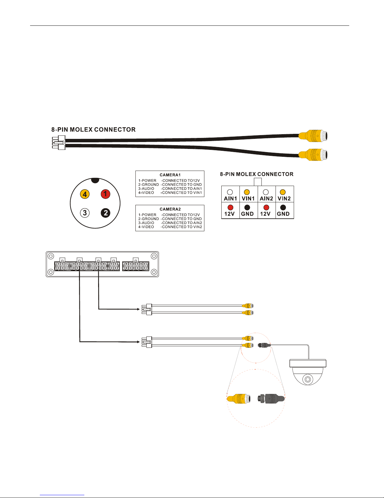
3.3 Camera Connection
Two different kinds of Audio & Video Cables for option:
1) 4-pin threaded cable with male connector for each camera (Pin 1: 12V power, Pin 2: GND, Pin 3: Audio Input,
Pin 4: Video Input).
With extension cable (3m, 5m and 10m option):
www.supercircuits.com MDVR21SD_RM
12
Page 13
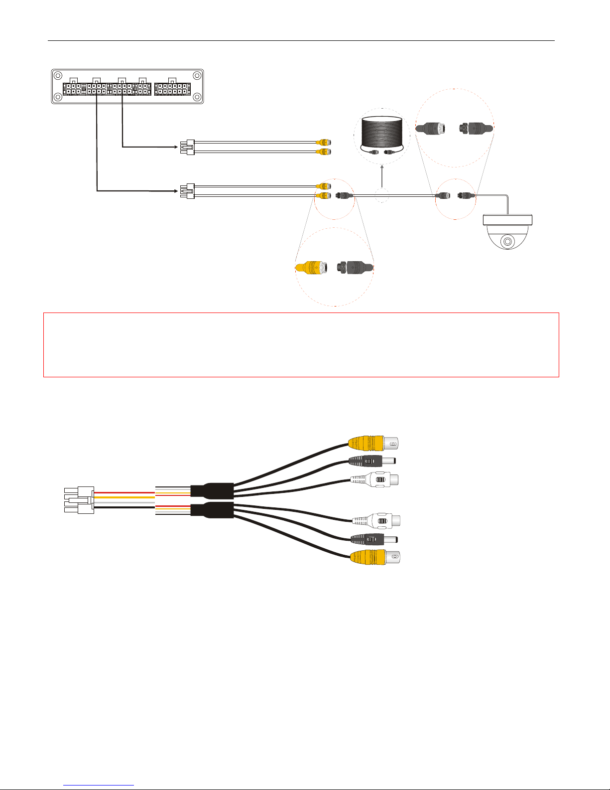
NOTE: The camera should with 4-pin female connector to match this cable. The DVR system will
provide stable 12V DC power to each camera, and record video and audio (if the camera is with
microphone built-in). This type of connection cable is highly recommended. It saves both installation
time and cost.
2) AV Input cable with BNC (Video, in yellow), RCA(Audio, in white) and DC connectors for each camera:
www.supercircuits.com MDVR21SD_RM
13
Page 14
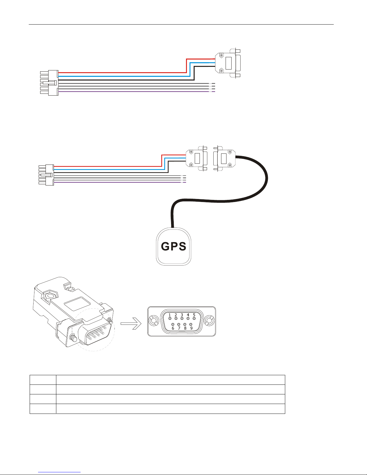
3.4 Sensor Harness Connection
GPS Connection (Option)
PIN Description
3 RXD2: Data receive
5 GND: Ground
9 +5V DC: Power output
www.supercircuits.com MDVR21SD_RM
14
Page 15
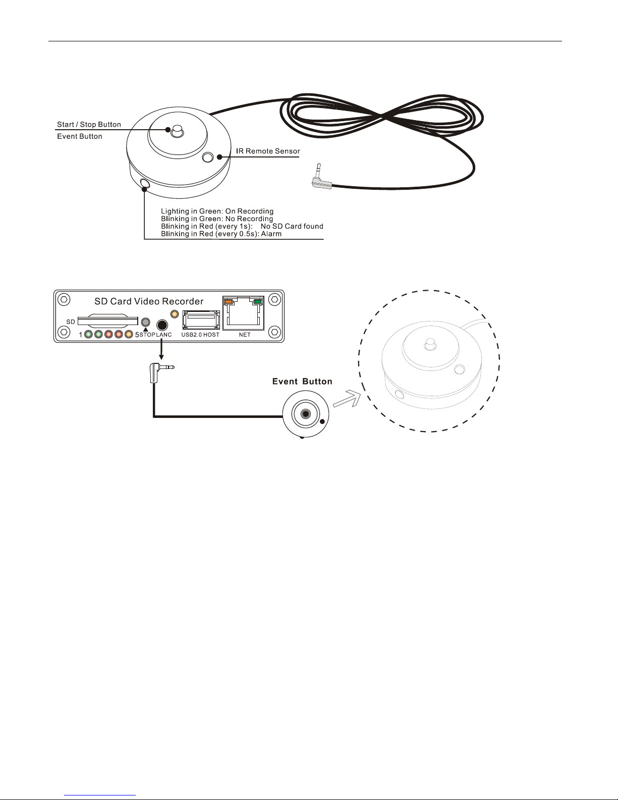
3.5 Event Button and Cable Connection (Option)
www.supercircuits.com MDVR21SD_RM
15
Page 16
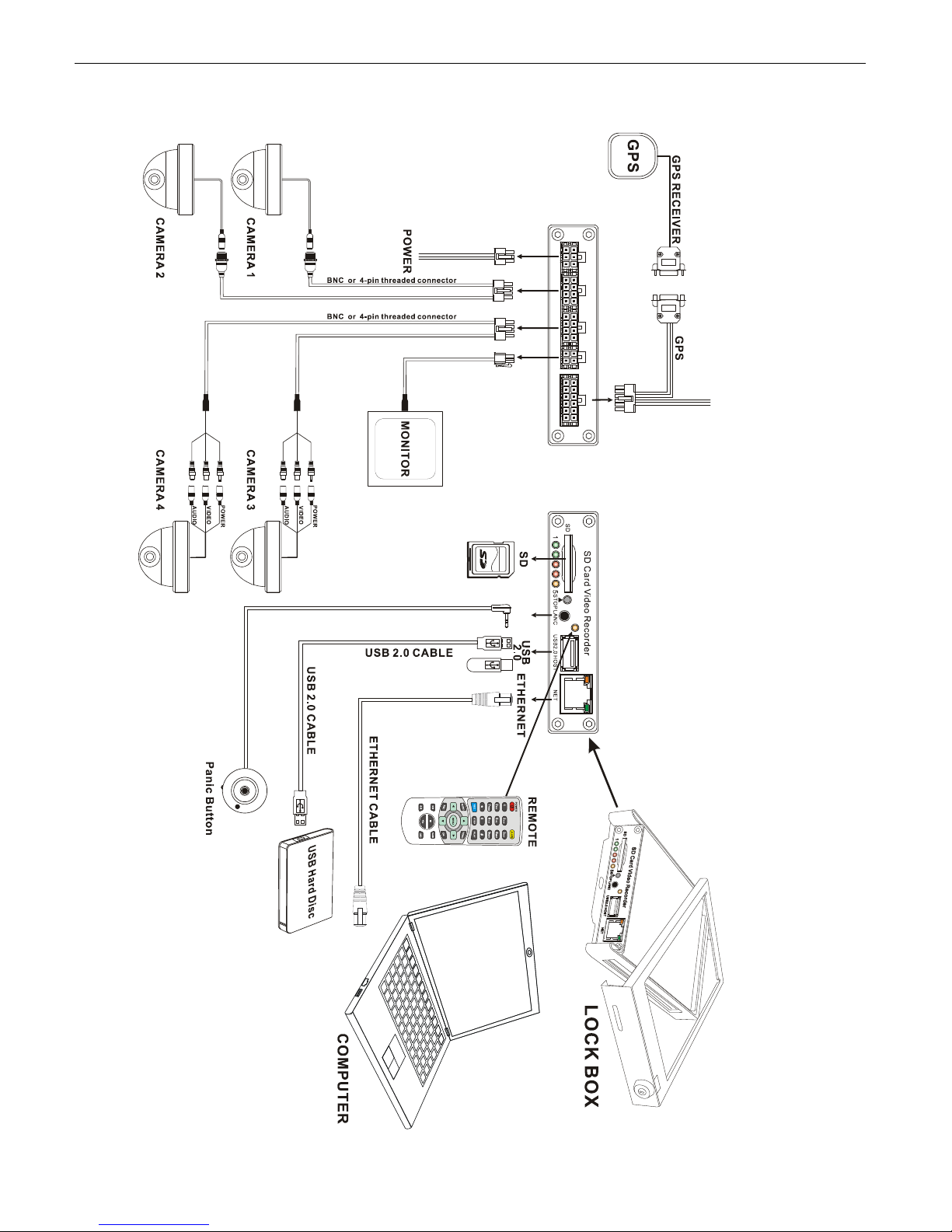
4. Main System Overview
www.supercircuits.com MDVR21SD_RM
16
Page 17
5. Basic Operation and Menu System
5.1 SD Card Formatting
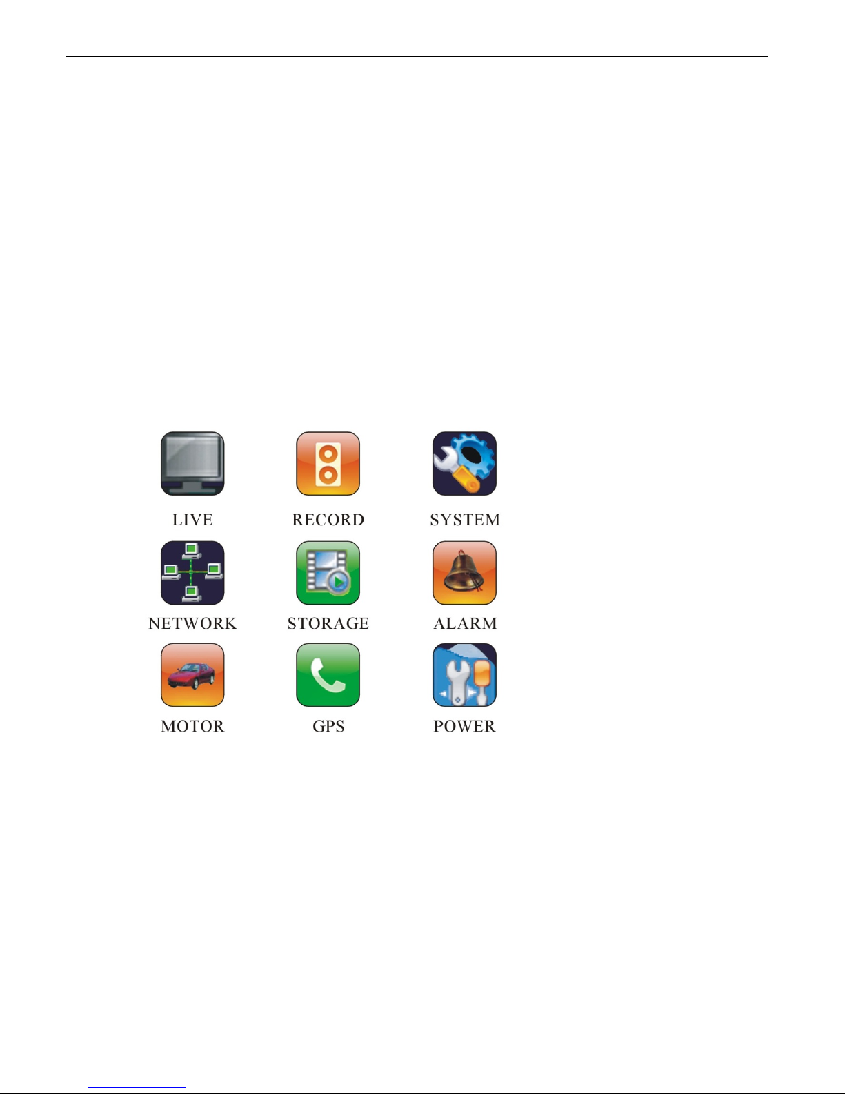
For a brand new SD Card of SDHC standard, it can be used directly. But with situations listed below, you’re required
to format it before using:
1) If the SD Card is of SDXC standard (like a 64GB SD Card), the defaulted file format is exFAT, which will not be
recognized by the DVR system. Y ou ha ve to format it b y using F AT32 file system on your PC. Partition Manager,
which can be downloaded from internet free of charge, is recomm ended t o be used for fast fo rmattin g and
batch processing.
2) If the SD Card is never formatted, or the file system is corrupted, you may have to format it before using. This
can be done on your PC by using FAT32 file system, or format it on the DVR system itself by following steps
given below:
3) Insert the SD Card into the SD Card slot on front pane l of the DVR system;
4) Press
<MENU> by remote to enter the DVR system menu;
a) Choose “STORAGE” and press
b) Go to “FORMAT” and press
www.supercircuits.com MDVR21SD_RM
<MENU> to get ready for formatting.
<MENU> to enter its sub-menu.
17
Page 18
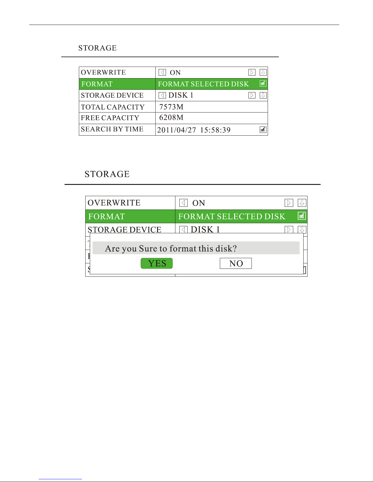
The format process will take some time, please wait. You will see the capacity of SD card after formatting.
5.2 Choose Recording Mode
Two recording modes for option: Composite Mode and Separate Mode. The defaulted recording mode is
“Separate Mode”. You can change to “Composite Mode” by steps given as below if needed:
a) Press
b) Choose ”RECORD” to enter it sub-menu;
c) Set the “CHANNEL MODE” as ”COMPOSITE MODE” ;
d) Press
e) Press
<MENU> by remote;
<MENU> to confirm;
<ESC> to save and exit.
www.supercircuits.com MDVR21SD_RM
18
Page 19
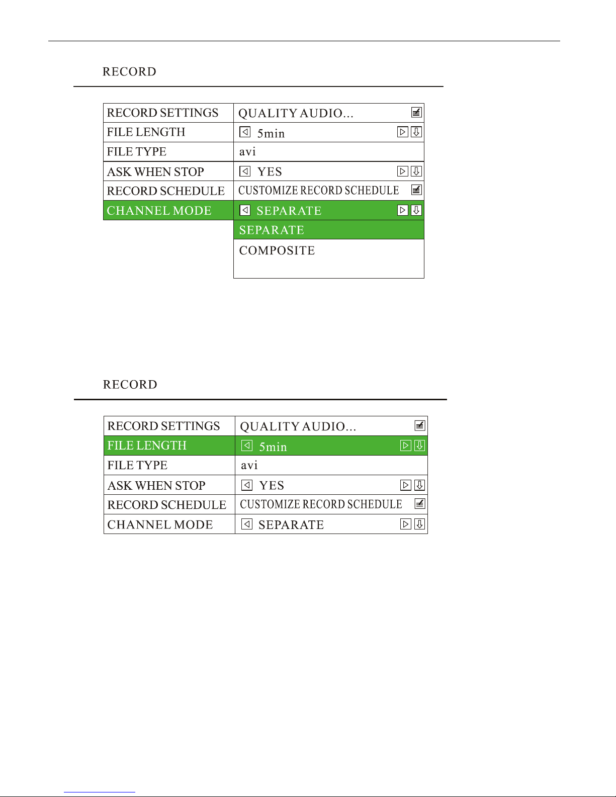
5.3 File Length
Options for file length: 5mins, 10mins, 15mins, 20mins, 30mins, 45mins and 60mins. The defaulted file length is 5
minutes. The maximum file length is 60 minutes.
5.4 Recording Quality
Press <MENU> to enter the DVR system menu, choose “RECORD” and enter its sub-menu, go to “RECORD
SETTINGS” and press
1) Setting Menu for Composite Mode:
www.supercircuits.com MDVR21SD_RM
<MENU> to enter.
19
Page 20
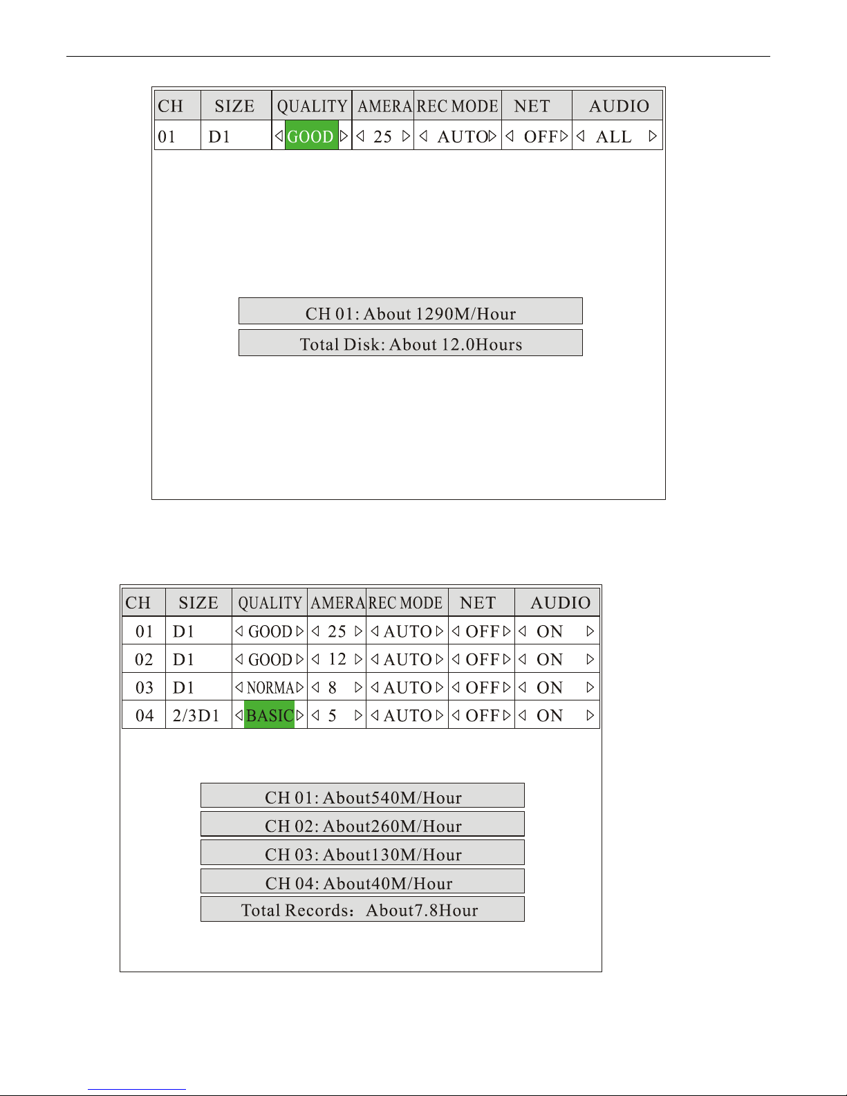
2) Setting menu for Separate Mode:
www.supercircuits.com MDVR21SD_RM
20
Page 21

3) Parameters for image qualit y levels:
Quality Resolution Still Image
Bitrate (Bit/s)
BASIC 2/3 D1
350K 210K 64K 198M/hour
Movement Image
Bitrate (Bit/s)
Audio Bitrate
(Bit/s)
File Capacity
( PAL: 480*384,
NTSC: 480*320 )
NORMAL D1
1000K 600K 64K 324M/hour
( PAL: 720*576,
NTSC: 720*480 )
GOOD D1
1200K 720K 64K 432M/hour
( PAL: 720*576,
NTSC: 720*480 )
HIGH D1
1500K 900K 64K 540M/hour
( PAL: 720*576,
NTSC: 720*480 )
CAUTIONARY NOTE: Maximum write speed for most SD card is about 6000KBit/s, so please select
“GOOD” or below if you are recording 4 channel video synchronously.
5.5 Start Recording
Press <REC> by remote to start recording. A red dot will be shown up at the top left corner of each camer a channel.
In Separate Mode, by default the DVR system will record all channels. If you want to record a specific channel(s), use
>< >< >< > or number key “1”, “2”, “3”, “4” to select the camera channel(s) and press <REC> to
<
start.
1) Quad image in Composite Mode:
www.supercircuits.com MDVR21SD_RM
21
Page 22
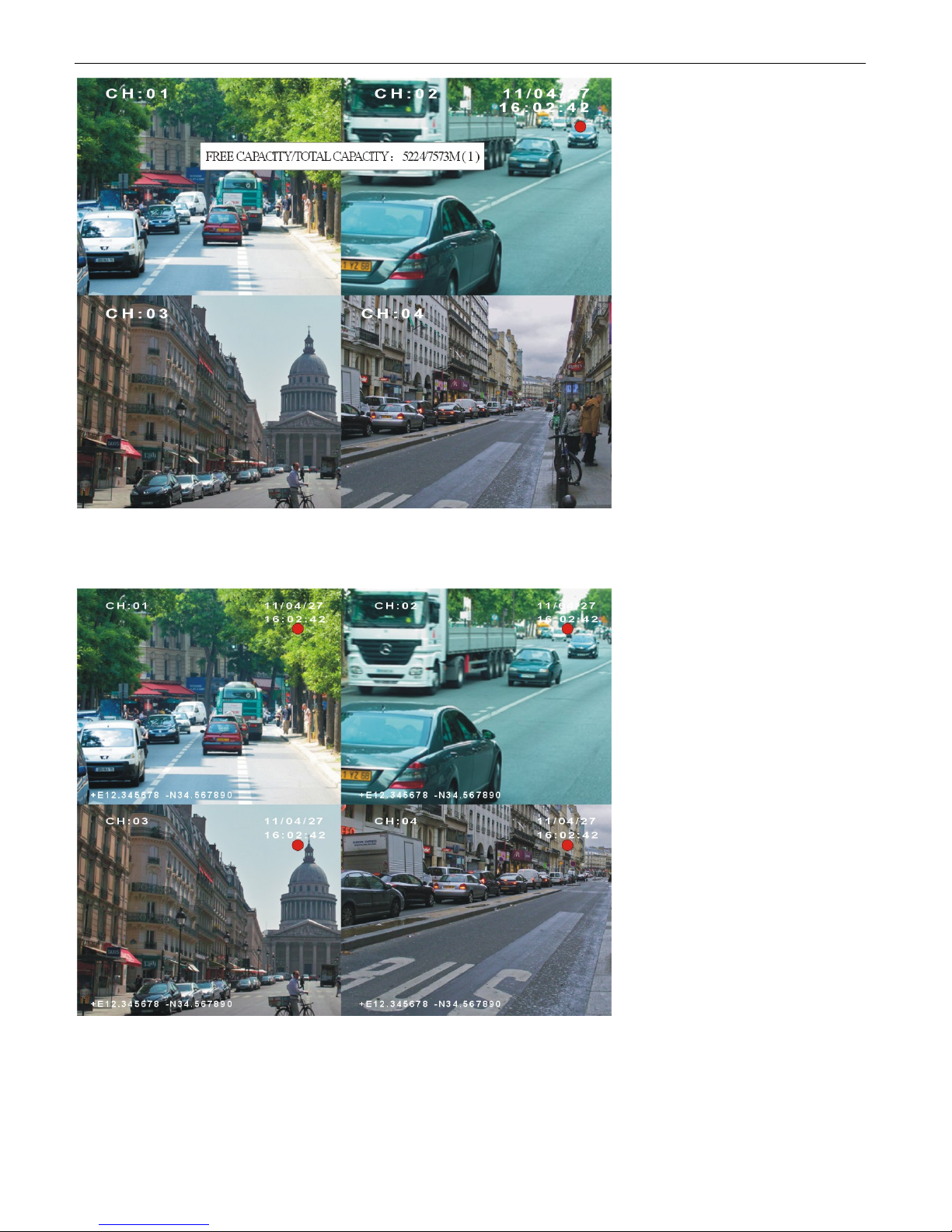
2) Quad Images in Separate Mode:
5.6 Playback Option
5.6.1 Playback files on DVR system
www.supercircuits.com MDVR21SD_RM
22
Page 23
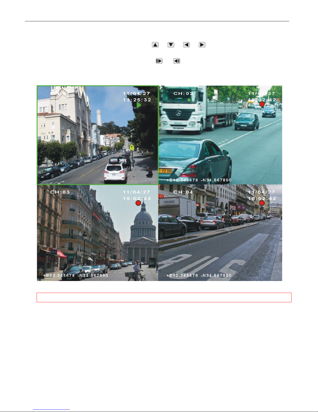
1) Play-back the latest record file(s) directly.
In “Separate Mode”, you can playback archive file when recording. P ress <PL AY> by remote, it will playback the
latest file of f irst camera channel (ch: 01). Use <
>< >< >< > or number key “1”, “2”, “3”, “4” to
select a specific camer a channel, and press <PLAY> to playb ack. The play status is indicated by a green triangle
on the top right corner of monitor. You can press <
>/< > to select a next or previous file. Toggle from
quad mode to full screen by pressing <VIDEO>.
NOTE: In “Composite Mode”, please stop recording before trying to playback any archive file.
2) Playback a specific archive file.
a) Press
<MENU> by remote to enter the DVR syst em menu, choose “STORAGE” and enter its sub-menu,
go to “SEARCH BY TIME” and press “MENU” to enter. All record directories will be listed for option. The
directories will be listed by order of the date and hour. To take “2011-04-27_14” f or an exampl e, it means
this directory contains all files recorded from 14:00:00 to 14:59:59 of April 27, 2011.
www.supercircuits.com MDVR21SD_RM
23
Page 24
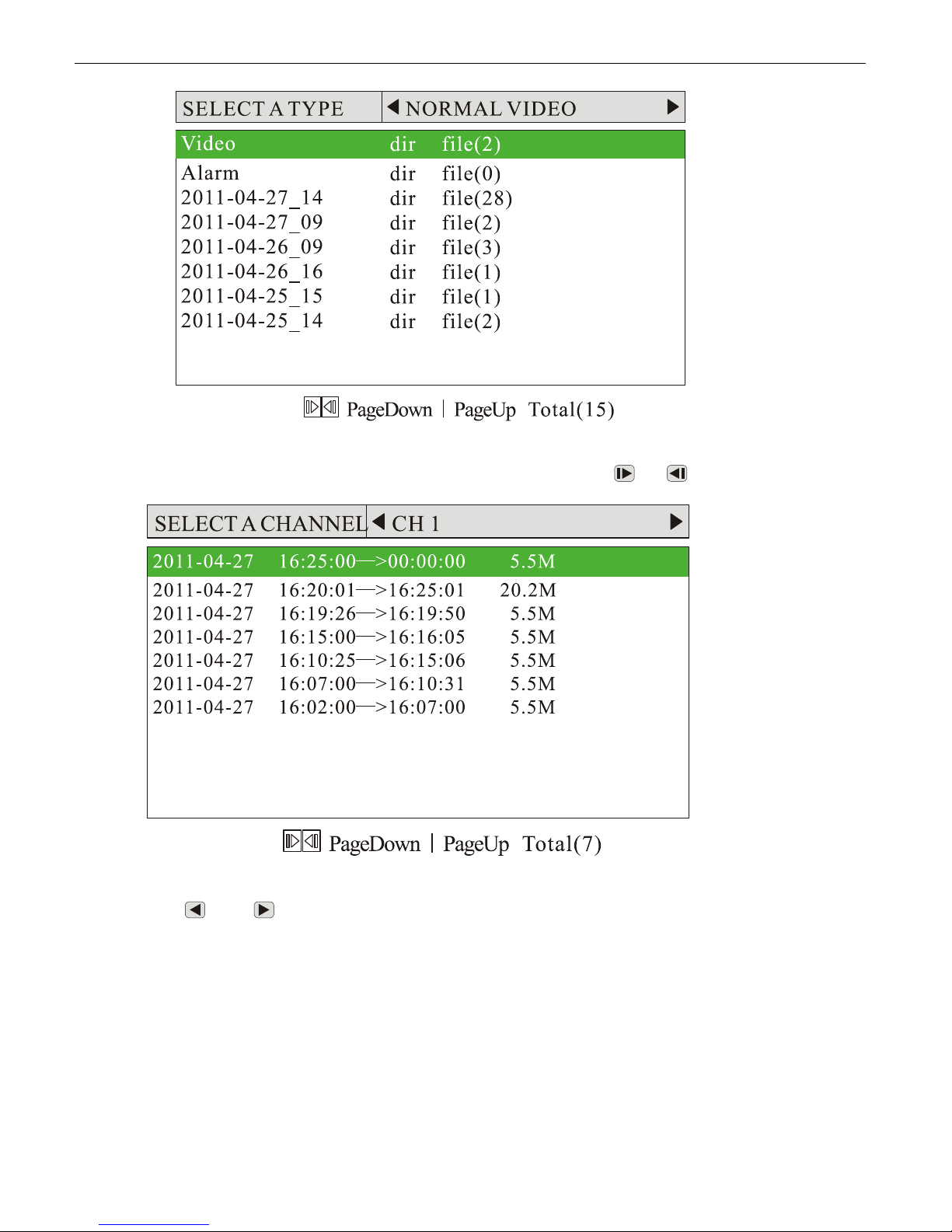
b) Press
<OK> or <MENU> by remote to enter a specific directory. All r ecord files of the specific hour will
be listed (The file with an ‘A’ suffix refers to Alarm Recording). Use<
c) Use <
> or < > to choose a file, and press <PLAY> to playback. By pressing <OK> or <MENU>,
details of the specific file will be shown up:
>/< > to turn a page.
www.supercircuits.com MDVR21SD_RM
24
Page 25
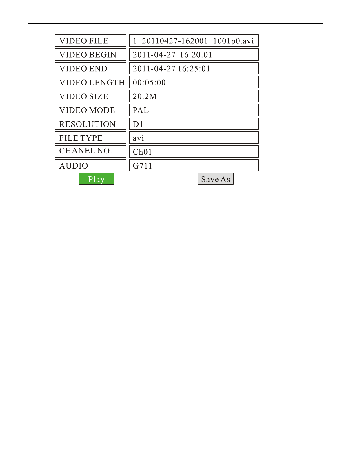
d) You can press “Play” to playback the file, or “Save As” to copy the f ile to an USB flash drive. To st op
playback, press
<STOP> by remote.
5.6.2 Playback the files on manufacturer’s PC Playback Software
a) Install “PC Playback Software.exe” included on the CD onto your PC ;
b) Remove the SD card from DVR system, and read on a PC by using a SD card reader, then run the PC Playback
Software to playback the files.
5.7, File Backup
a) Insert an USB flash drive into USB port on front panel of the DVR system;
b) Press
c) Go to “SEARCH BY TIME” and press
d) Enter one directory and select a specific file needed to be copied, press
e) Choose “Save As” and press
<MENU> by remote, choose “STORAGE” and press <MENU> to enter its sub-menu;
<MENU> to enter the record directories;
<OK> or <MENU> to confirm;
<MENU> to confirm, the selected file will be copied.
5.8 Alarm Recording
5.8.1 Setup The Alarm Action
The DVR system can be connected to 3 sensor (alarm) inputs. All these sensors (alarms) can trigger alarm recording.
They can also turn on the buzzer, trigger to toggle video display , and trigger to show informatio n on screen. Here is
a diagram for sensor (alarm) cable & connector:
www.supercircuits.com MDVR21SD_RM
25
Page 26
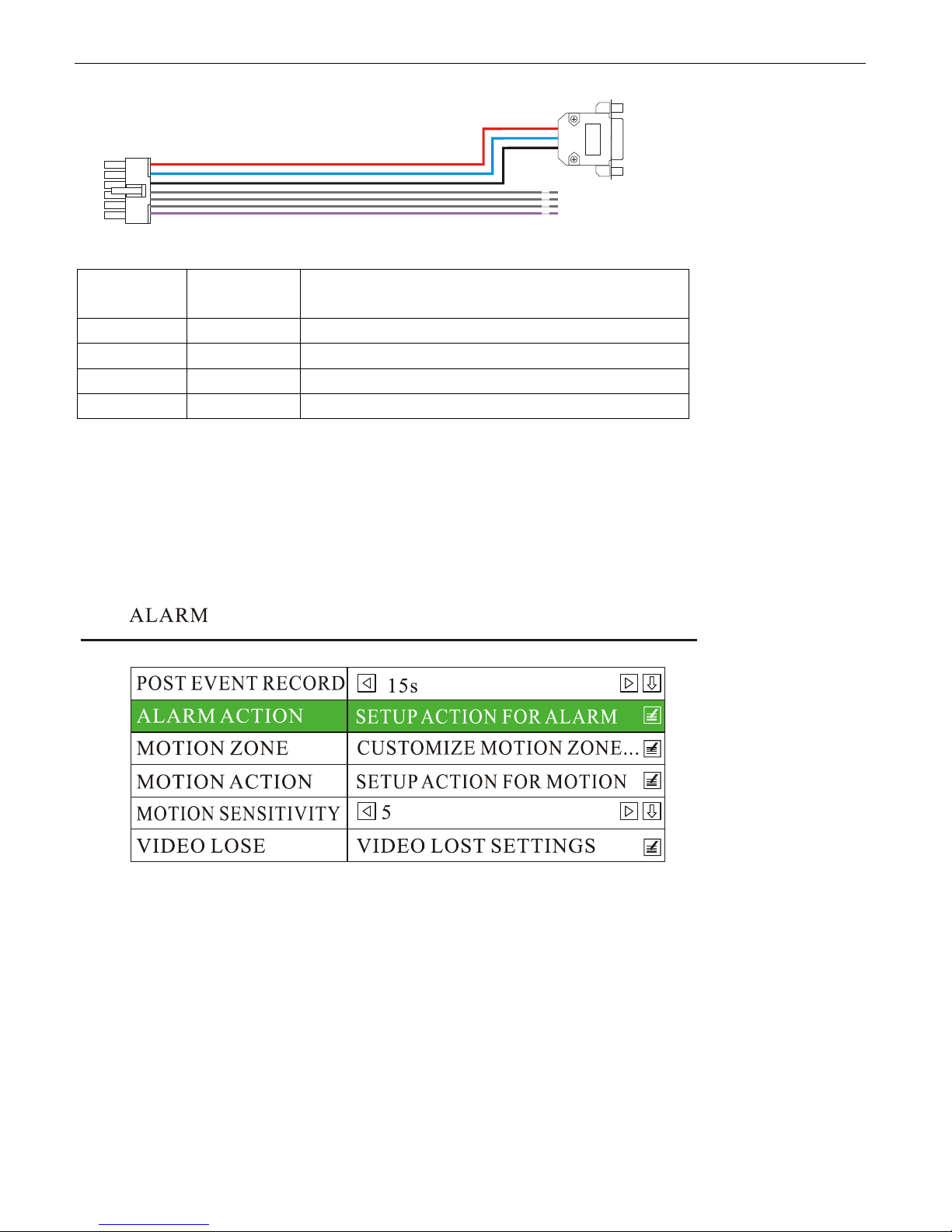
LABEL Color Description
SENSOR1 Brown Sensor(Alarm) 1
SENSOR2 Brown Sensor(Alarm) 2
SENSOR3 Brown Sensor(Alarm) 3
SENSOR4 Violet Speed Sensor
<MENU> by remote to enter the DVR system menu, choose “RECORD” and press <MENU> to enter its
Press
sub-menu, go to “RECORD SETTINGS” and press
change it to “MANUAL” by press
<MENU>, press <OK> to save and exit.
<MENU> by remote to enter the DVR system menu, choose “ALARM” and press <MENU> to enter its
Press
sub-menu. Go to “ALARM ACTION” and press
<MENU> to enter. The defaulted “REC MODE” is “AUTO”,
<MENU> to enter.
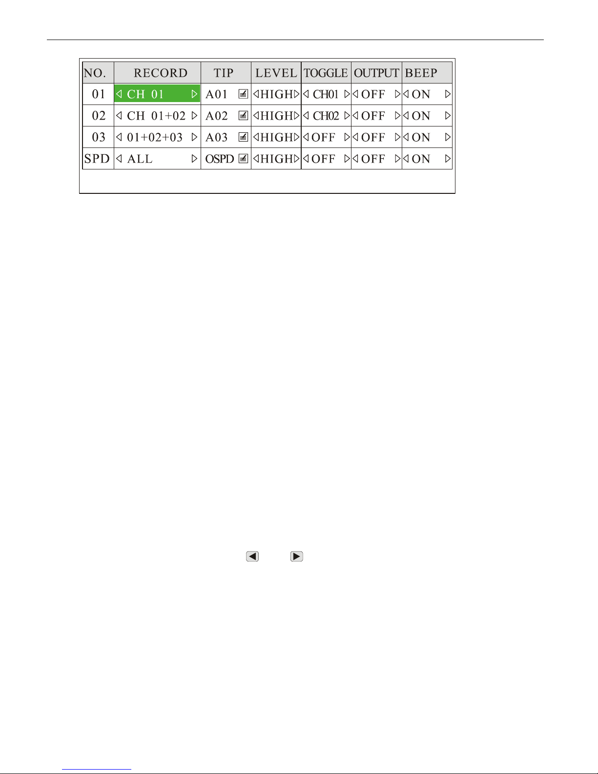
Taking “01+02+03” for an example, channel 1, 2 & 3 will start to record when th e sensor (alarm) 3 is triggered. The
“LEVEL” is set to “HIGH”, which means the “sensor(alarm) 3” will be enabled if it is connected to the HIGH level
(+12V). If you need the “sensor(alarm) 3” to be triggered by LOW level (GND), you should set this to be “LOW”. If
you set the “TOGGLE” as “CH 01”, the screen will toggle to CH 01 in full screen automatically when “sensor(alarm) 3”
is triggered.
www.supercircuits.com MDVR21SD_RM
26
Page 27
When alarm recording is trigged, a yellow blinking dot will be displayed on the top right corner.
Remarks for each option:
NO.: SENSOR 1, SENSOR 2, SENSOR3.
RECORD: Choose the channel(s) to start to record when the sensor(alarm) rec ording is triggered. There are a total
of 16 modes: OFF, CH 01, CH 02, CH 01+02, CH 03, CH 01+03, CH 02+03, 01+02+03, CH 04, CH 01+04, CH 02+04,
01+02+04, CH 03+04, 01+03+04, 02+03+04, ALL.
TIP: Information to be shown on screen. There is a dialog box f or inputting the text. Maximum: 4 characte rs. There
are four alarm sources: A01: Sensor1, A02: Sensor2, A03: Sensor3 and OSPD: Over Speed.
LEVEL: HIGH / LOW; High means Alarm input voltage higher than 5V, and Low means lower than 3V.
TOGGLE: It will toggle to the camera you set in full scr een automatically when sensor(alarm) is triggered . There are
a total of 5 modes: OFF, CH01, CH02, CH 03, CH04.
OUTPUT: OFF (ON is not available yet).
BEEP: ON / OFF.
5.8.2 Post Event Record
The DVR system can implement post-recording in modes of alarm recording a nd m ot io n de te ctio n re co rdin g. T hat
means, the DVR system will keep recording for scheduled time after alarm recording completes.
1) Press
2) Choose “AL ARM” and press
<MENU> by remote to enter the DVR system menu;
<MENU> to go to its sub-menu;
3) Go to “POST EVENT RECORD” and use <
60s, 180s available).
4) Press
<OK> to save the setting and exit.
www.supercircuits.com MDVR21SD_RM
> or < > to set the post-recording time(0s, 10s, 20s, 30s, 45s,
27
Page 28
5.9 Motion Detection
5.9.1 Set Motion Detection Zone
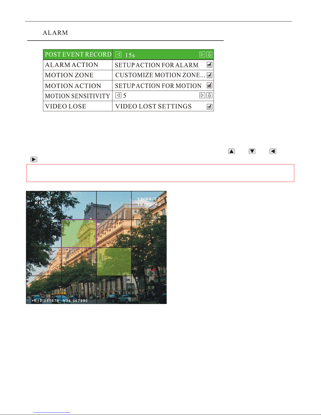
<MENU> by remote to enter the DVR system menu, choose “ALARM”, go to “MOTION ZONE” and press
Press
<MENU> to set the area: Choose the zone(s) which you want to monitor by using < > , < > , < > and
>.
<
NOTE: Please press
than one zone.
<MENU> by remote to confirm after choosing each zone if you need select more
5.9.2 Set Motion Detection Action
Press
<MENU> to enter the DVR system menu, choose “ALARM” to enter its sub-menu, go to “MOTION
ACTION” and press
<MENU> to enter, set the “RECORD” as “ON”, press <OK> to save and exit. When motion
detection is triggered, you will see a yellow dot flashing at the upper right corner.
www.supercircuits.com MDVR21SD_RM
28
Page 29
5.9.3 Set Motion Sensitivity
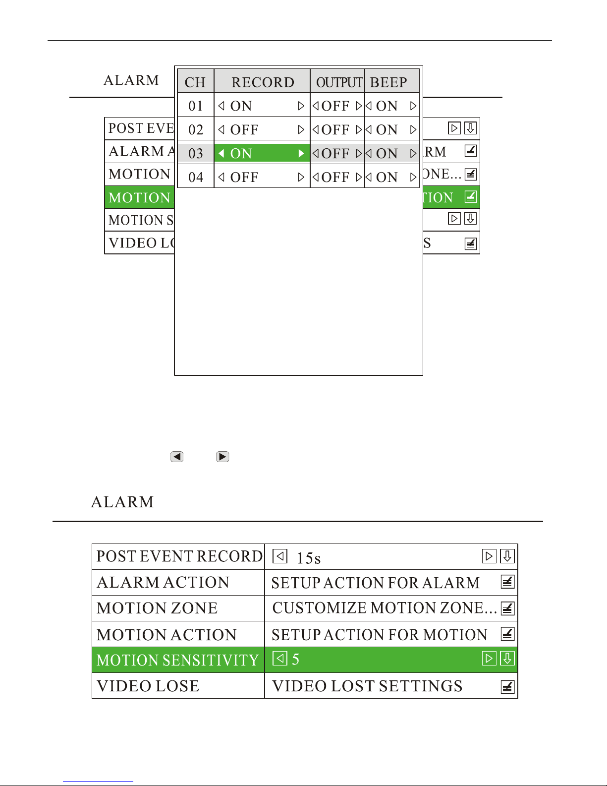
Press
<MENU> to enter the DVR system menu, choose “ALARM” to enter its sub-menu, go to “MOTION
SENSITIVITY”, and press <
> or < > to sensitive level (1~9 levels for option). “1” refers to lowest sensitive
level, and “9” refers to highest.
www.supercircuits.com MDVR21SD_RM
29
Page 30
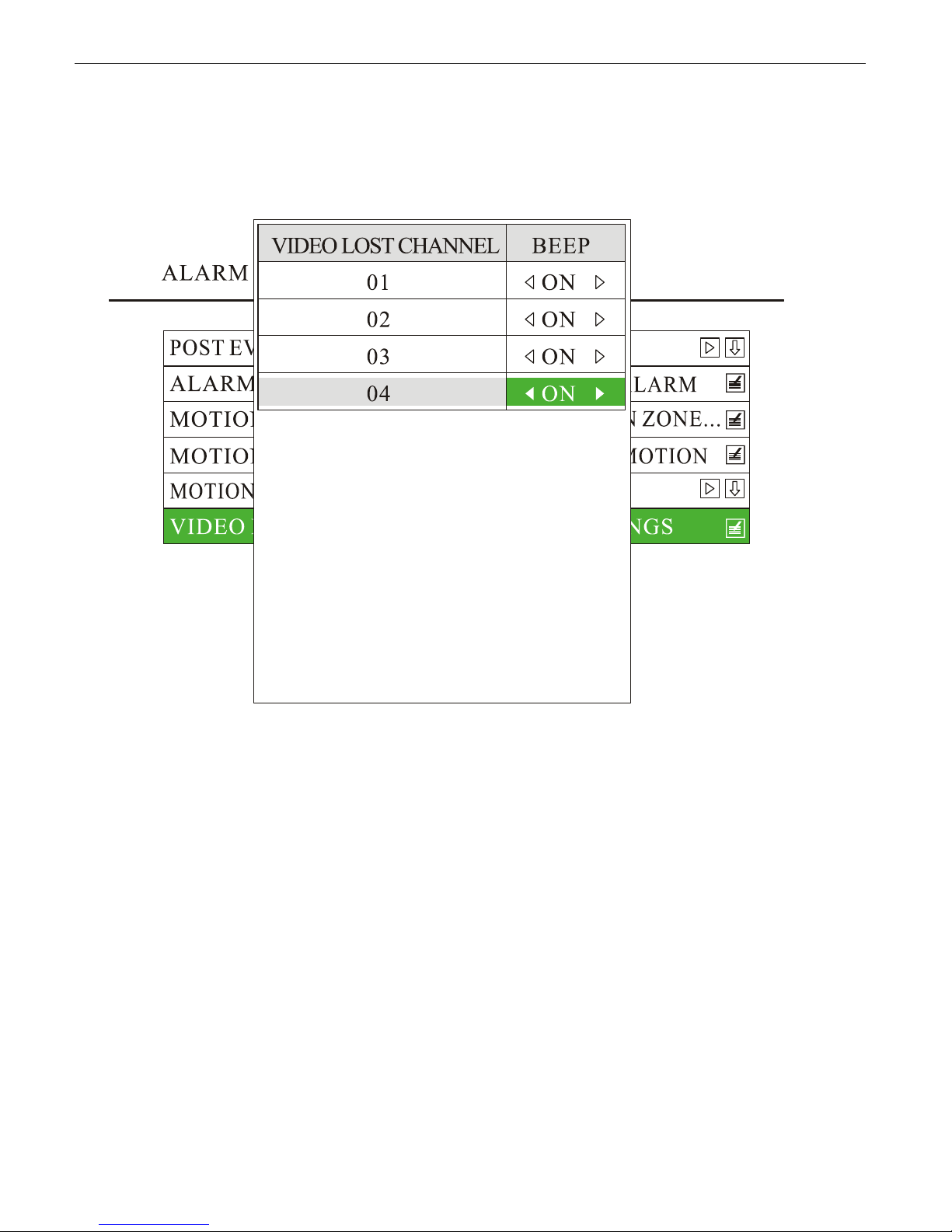
6.0 Video Lost Alarm
The buzzer can be set as “ON” to trigger the beeper when any video lost. Pres s
menu, choose “ALARM” and press
“ON”, press
<OK> to save and exit.
<MENU> to enter its sub-menu, go to “VIDEO LOST” and set the buzzer as
<MENU> to enter the DVR system
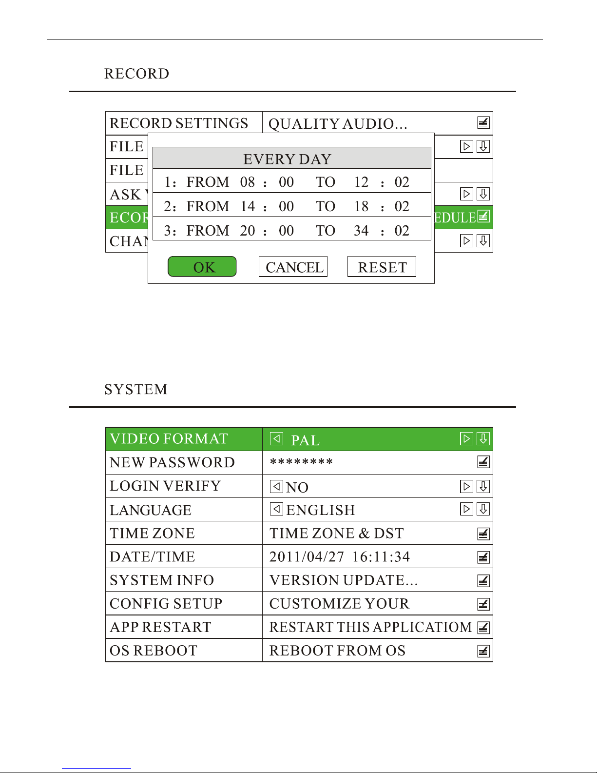
6.1 Schedule Recording
<MENU> by remote to enter the DVR system menu, choose “RECORD” and press <MENU> to enter its
Press
sub-menu, go to “RECORD SETTINGS” and press
change it to “MANUAL” by press
<MENU>, press <OK> to save and exit. Go to “RECORD SCHEDULE” and set
the recording time.
www.supercircuits.com MDVR21SD_RM
<MENU> to enter. The defaulted “REC MODE” is “AUTO”,
30
Page 31
6.2 Video System Setting
<MENU> to enter the DVR system menu, Choose ”Sy stem” to enter its sub-menu, se t the “VIDEO FORMAT”
Press
as PAL or NTSC, and press
<OK> to save and exit.
www.supercircuits.com MDVR21SD_RM
31
Page 32

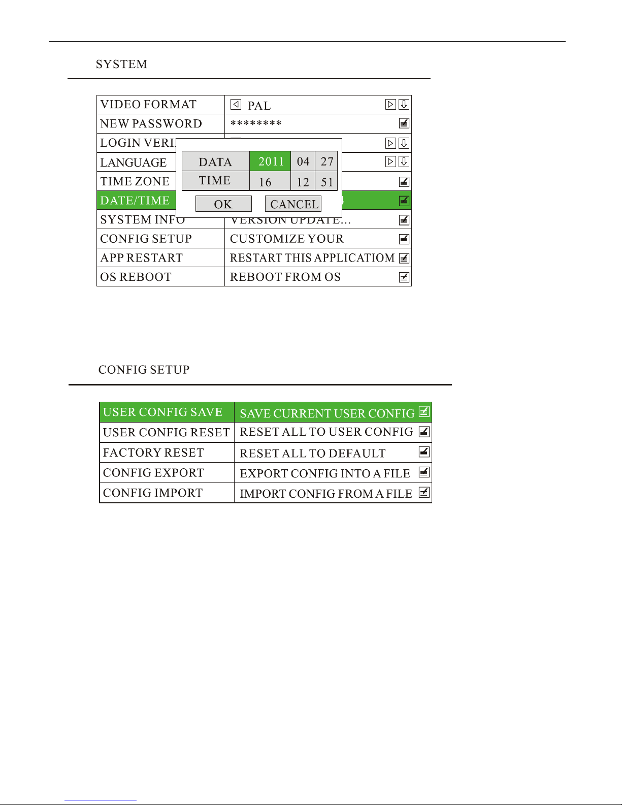
6.3 Set Date and Time
6.3.1 Set Date Display Format
<MENU> to enter the DVR system menu, choose “SYSTEM” and press <MENU> to enter its sub-men, go
Press
to “TIME ZONE” and set the “DATE FORMAT”, “YY/MM/DD”, “MM/DD/YY” or “DD/MM/YY”.
6.3.2 Set The Time Zone
Press
<MENU> to enter the DVR system menu, choose “SYSTEM” and press <MENU>to enter its sub-menu,
choose “TIME ZONE” and press
<MENU> to enter, go to “TIME ZONE” and select the right time zone.
6.3.3 Set Date and Time
<MENU> to enter the DVR system menu, choose “SYSTEM” and press <MENU> to enter its sub-menu, go
Press
to “DATE/TIME” and press
www.supercircuits.com MDVR21SD_RM
<MENU> to set date and time, press <OK> to save and exit.
32
Page 33
6.4 Configuration Setup
Press <MENU> to enter the DVR system menu, choose “SYSTEM” to enter its sub-menu, go to “CONFIG SETUP”
and press
<MENU> to enter, and customize your configuration.
1) User Config Save
If some system configurations are modified, and you want to make a save copy for this, please choose “USER
CONFIG SAVE” and press
<MENU>, all configuration modif ications will be save to internal flash of the DVR
system.
2) User Config Reset
If some improper modifications have been done, and you would like to reset to the previous configuration that you
have saved, please choose “USER CONFIG RESET” and press
3) Factory Reset
The user can press “FACT ORY RESET” to r eset to the factory defaulted settings. After this is pr essed, the system will
restart automatically.
4) Config Export / Import
Press “CONFIG EXPORT”, the settings will be saved automatically onto the SD card. If the same configuration is
required for other DVR systems, just insert the SD card into the DVR, and choose “CONFIG IMPORT” to import the
settings. After importing successfully, the DVR system will restart automatically.
www.supercircuits.com MDVR21SD_RM
<MENU> to reset.
33
Page 34
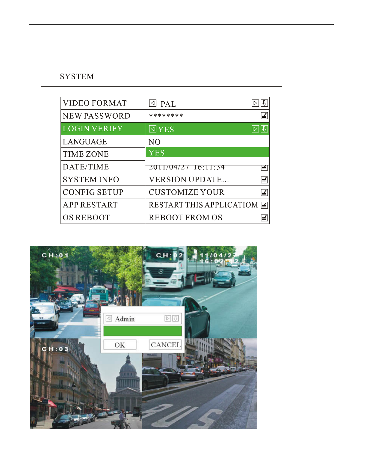
6.5 User Level and Password Setting
The defaulted system enter is with no password. To set the user name and password,
1) Press
<MENU> to enter the DVR system menu, choose “SYSTEM” and press <MENU> to enter its
sub-menu, set the “LOGIN VERIFY” to be “YES”, press
<OK> to save and exit.
2) Escape from the DVR system menu, when enter again, you will be required for use name:
www.supercircuits.com MDVR21SD_RM
34
Page 35
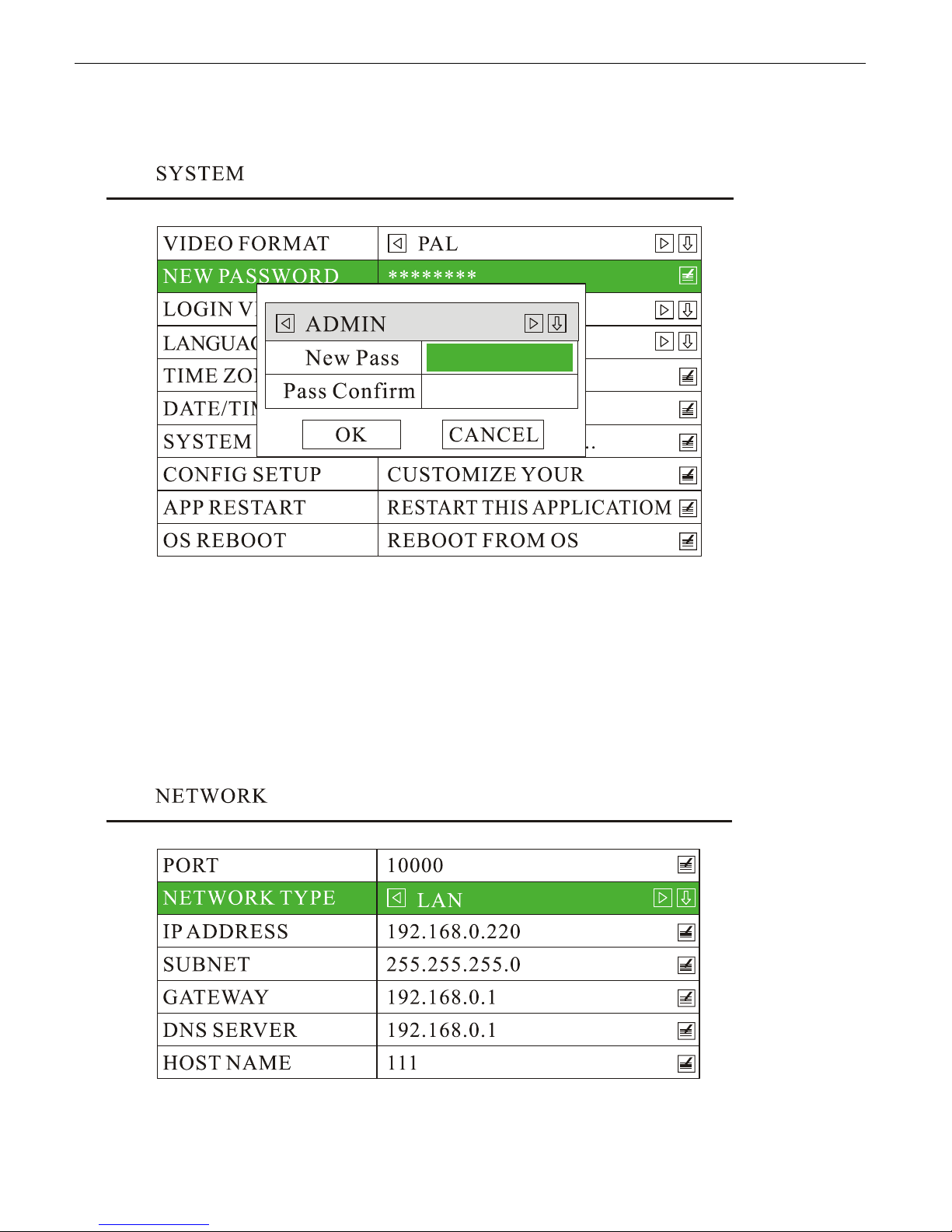
3) The system is defaulted to be entered with no password. If password is required, go to “NEW P ASSWO RD” and
set the password. Input the same password in both rows of “New Pass” and “Pass Confirm”, press
<OK> or
<MENU> to save and exit.
6.6 Network Setting
The system supports both Static IP and Dynamic IP. Press <MENU> to enter the DVR system menu, choose
“NETWORK” and press
“DHCP” (Dynamic IP).
1) If it is static IP mode, you may choose “IP ADDRESS”, “SUBNET”, “GATEWAY” and “DNS SERVER” to set each
option.
<MENU> to enter its sub-menu, go to “NETWORK TYPE” and set it as “LAN” (Static IP) or
www.supercircuits.com MDVR21SD_RM
35
Page 36
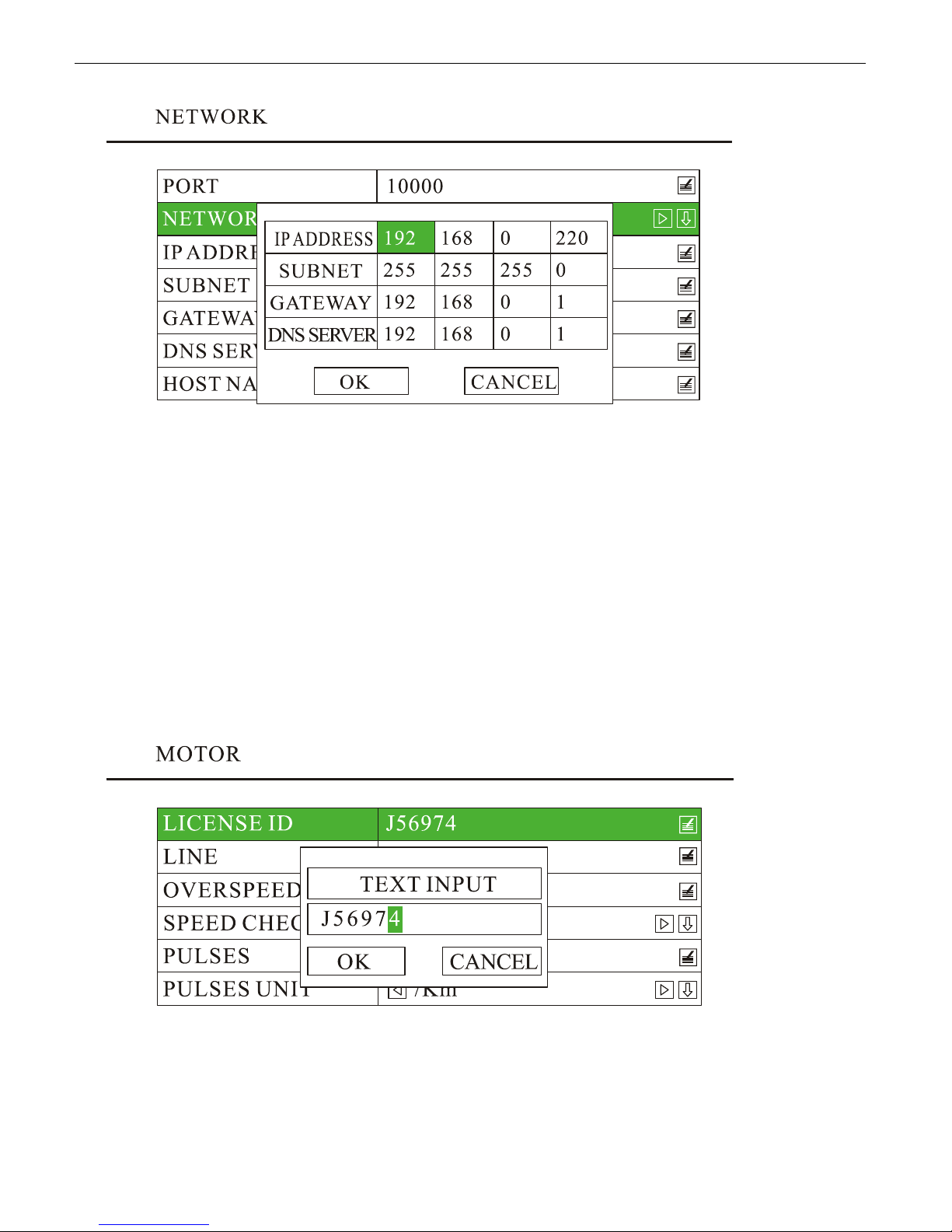
After setting, please press
<MENU> or <OK> to save and exit.
2) If it is dynamic IP, the system will configure the IP address automatically.
3) ”HOST NAME” is used for setting the DVR system’s name.
6.7 MOTOR
6.7.1 Set “LICENSE ID” and “LINE”
<MENU> to enter DVR system menu, choose “MOTOR” and press <MENU> to enter its sub-menu. Set
Press
the “LICEN SE ID” and “LINE”, press “OK” to save and exit. The information will be displayed at the top left corner.
www.supercircuits.com MDVR21SD_RM
36
Page 37
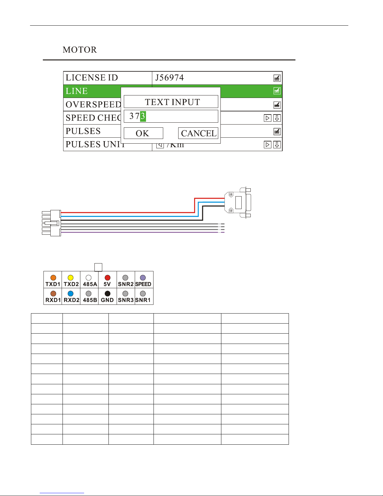
6.7.2 Get Speed from GPS
Pin No. Description Color Description GPS Connector
1 TXD1 Vacant TXD, COM1, (GPS)
2 TXD2 Vacant TXD, COM2
3 485A Vacant RS485 A, (PTZ)
4 5.0V Red +5 VDC Pin 9
5 SNR2 Grey Sensor 2
6 SPEED Violet Speed sensor
7 RXD1 Vacant RXD, COM1, (GPS)
8 RXD2 Blue RXD, COM2 Pin 3
9 485B Vacant RX485 B, (PTZ)
10 GND Black Ground Pin 5
11 SNR3 Grey Sensor 3
12 SNR1 Grey Sensor 1
www.supercircuits.com MDVR21SD_RM
37
Page 38
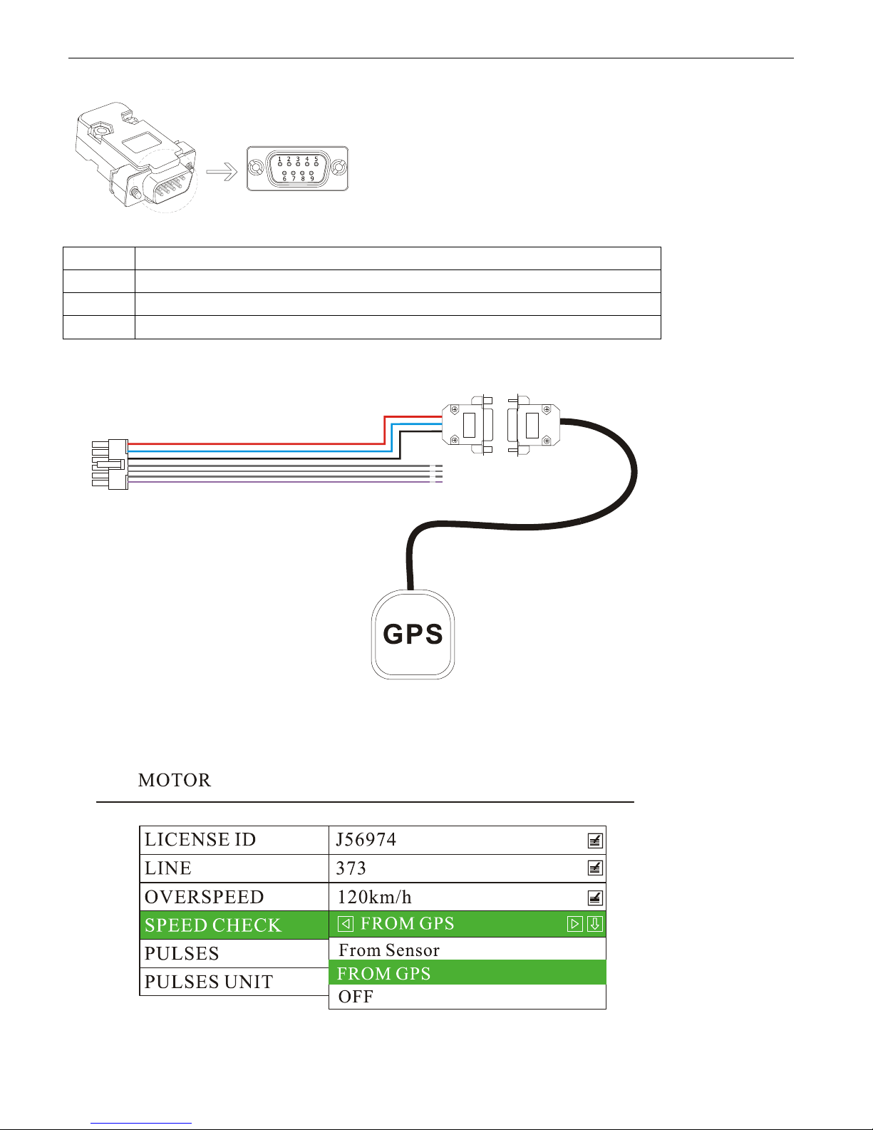
GPS connector (RS232 COM1)
PIN Description
3 RXD2: Data receive
5 GND: Ground
9 +5V DC: Power output
1) Connect GPS receiver to DVR system through the sensor harness:
2) Press
<MENU> to enter DVR system menu, choose “MOTOR” and press <MENU> to enter its sub-menu,
set the “SPEED CHECK” as “From GPS”, and press “OK” to save and exit.
www.supercircuits.com MDVR21SD_RM
38
Page 39
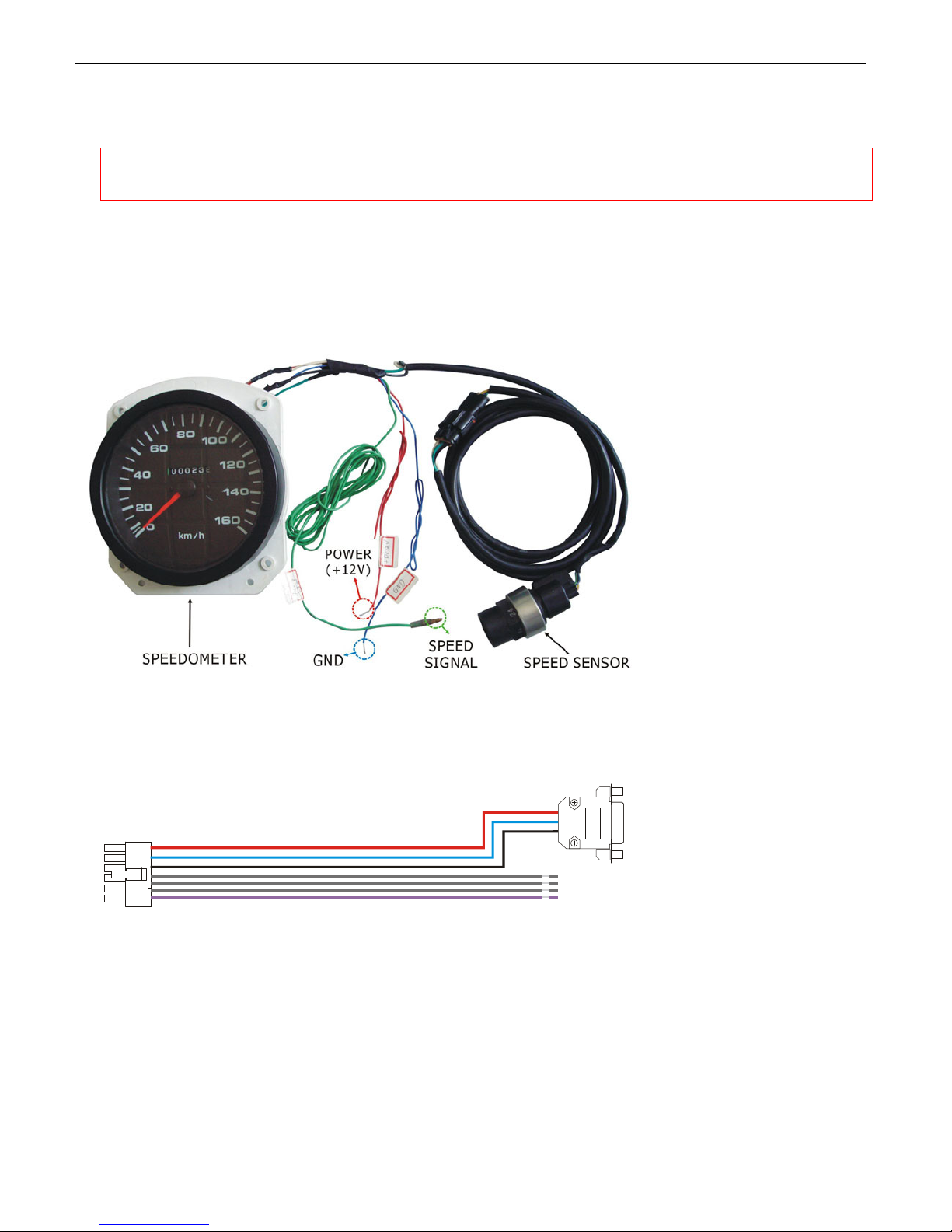
3) The speed will be displayed on the left bottom of the monitor. If you need the speed to be “MPH” other than
“KM/H”, please select “mile” in the “PULSES UNIT”.
NOTE: If no GPS device is connected to the DVR system, speed on monitor will stay as “0.0KMH”.
To hide this information, set the “SPEED CHECK” as “OFF”.
6.7.3 Get Speed from Speedometer.
1) Connect the speed sensor harness (in Violet color) to speedometer.
2) If the speedometer already has a signal output wire (showed as SIG output in the following diagram), you can
connect “Speed sensor input” wire to the SIG output wire directly.
www.supercircuits.com MDVR21SD_RM
39
Page 40
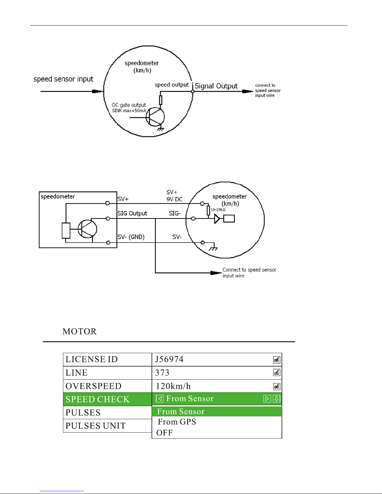
3) If the speedometer does NOT have a signal output wire, please connect to the output of speed sensor. This could
also be input of the speedometer.
4) Press
<MENU> to enter DVR system menu, choose “MOT OR” and press <MENU> to enter its sub-menu, set
the “SPEED CHECK” as “From Sensor”, and press
<OK> or <MENU> to save and exit.
5) Calculate the pulse number the speed sensor generates for one kilometer. Usually the speed sensor will generate
www.supercircuits.com MDVR21SD_RM
40
Page 41
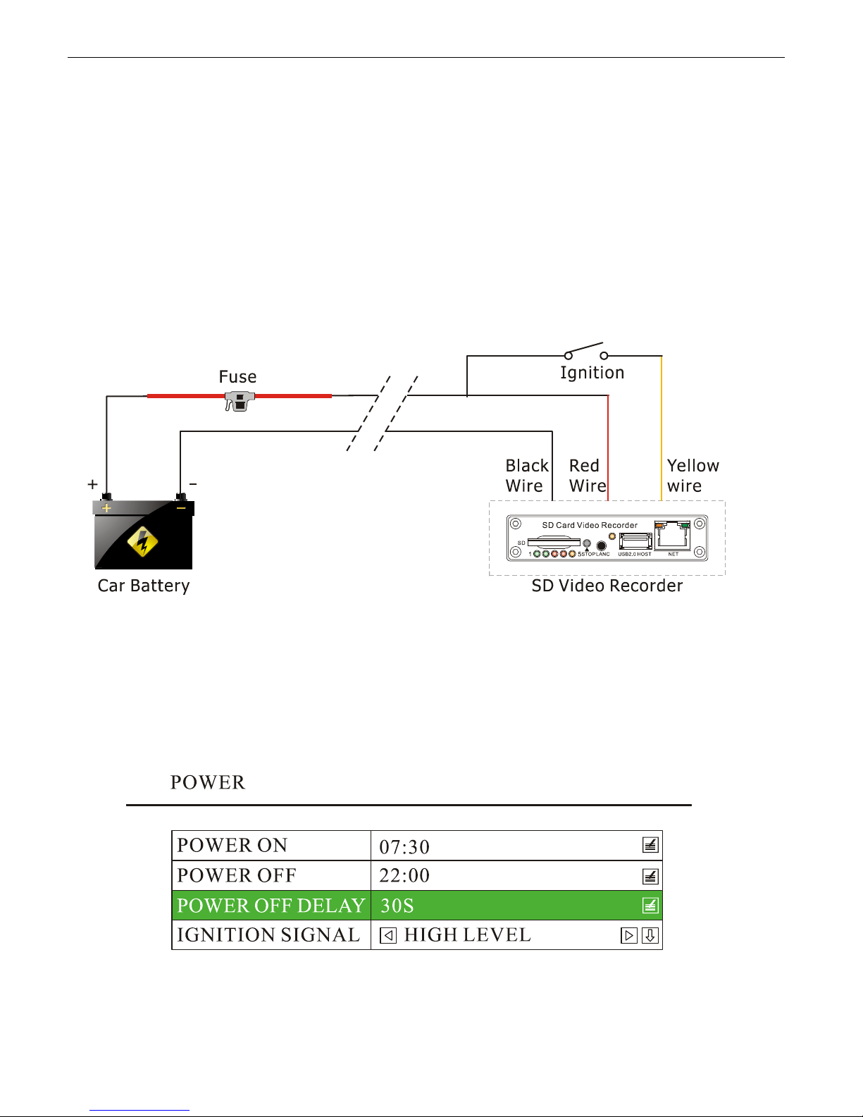
8 or 16 pulses if the wheel goes one round and you need to calculate the number of the pulse that the speed
sensor will generate if the car runs for one kilometer. Then set the number to “Pulse No.”.
6) While in a real application, it’s not easy to pulse number by the calculation on the paper. In this case, you can
choose the menu item “10 Vehicle Setup”, then set the “Pulse No.” to be “0”. Then you drive the car for one
kilometer. The number in the “Pulse No.” will increase as you are driving. The number showed in the “Pulse
No.” once you get to one kilometer would be the number you need.
6.8 Manage the power
6.8.1, Use ignition switch to turn on/off the DVR system
1) Connect ignition switch to the yellow wire of power supply cable, and red / black wire to the “+” / “-” pole of the
car battery. The DVR system will be turned on when the ignition switch is in the ON position, and commences
recording. To stop the recording process, place the system switch in the OFF position.
2) If the OFF DELAY op tion is enabled, the DVR will continue to record for the pr escribed number of seconds. When
the off-delay expires, the camera and DVR system shut off.
3) Set OFF DELAY. Press
<MENU> to enter the DVR system menu, choose “POWER” and press <MENU> to
enter its sub-menu. Go to “POWER OFF DEL AY” and set the number of seconds. The maximu m number you can
input is 86400 seconds (24 hours). If the number is set to 0, the camera and DVR system shut off right after the
ignition switch if in the OFF position.
4) If the vehicle is using low level as ignition signal, you need to set the “IGNITION SIGNAL” as “LOW LEVEL”.
www.supercircuits.com MDVR21SD_RM
41
Page 42
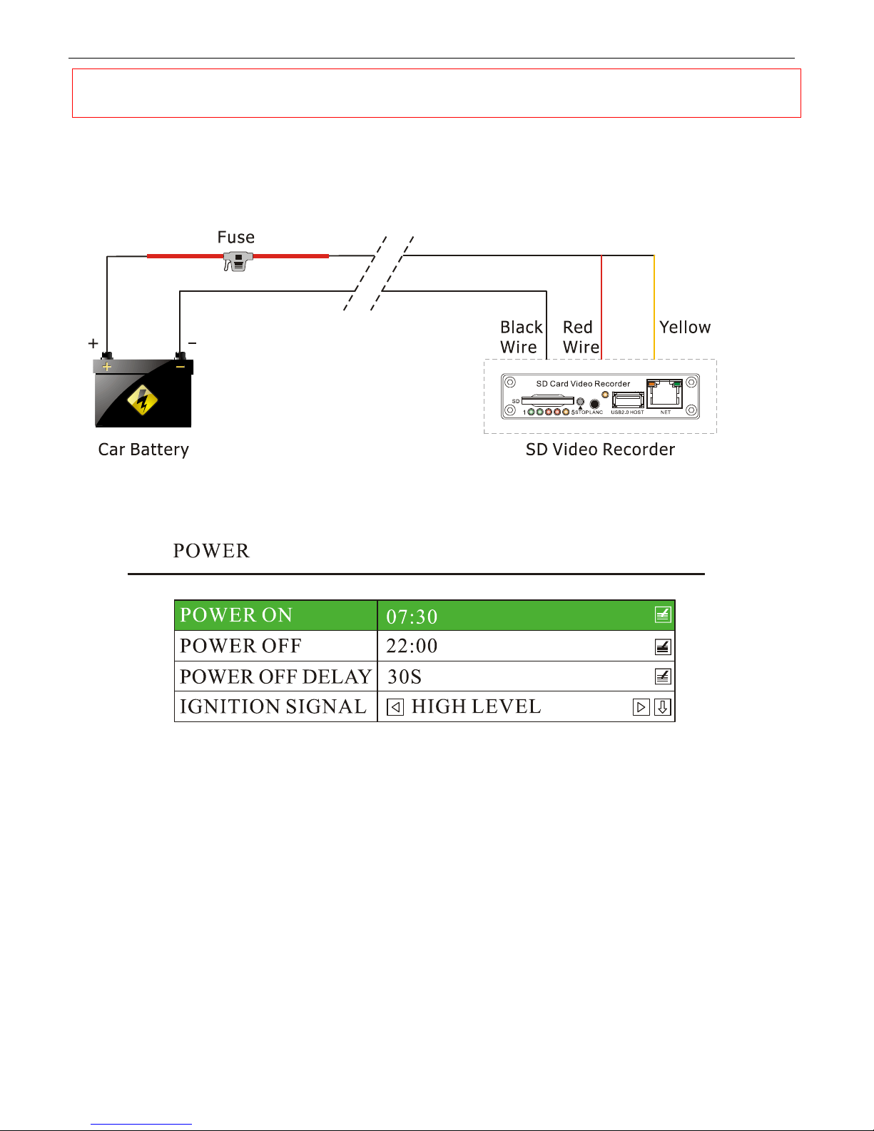
NOTE: If the vehicle uses low level as ignition signal, you need to set the “IGNITION SIGNAL” as
“LOW LEVEL” .
6.8.2, Turn On / Off DVR System Automatically
1) Connect the DVR system to car battery as diagram shown below . Note: Please connect the yellow wire (ignition
wire) to the “+” pole (+12V or +24V) of car battery.
2) Press
<MENU> to enter DVR system menu, choose “POWER” and press <MENU> to enter its sub-menu.
a) Go to “POWER ON” and set the time you would like the DVR system to be turned on.
b) Go to “POWER OFF” and set the time you would like the DVR system to be turned off.
c) If turning on/off automatically is not required, leave the “POWER ON” and “POWER OFF” time as “0000” by
defaulted.
www.supercircuits.com MDVR21SD_RM
42
Page 43

6.9 Use PTZ
6.9.1 PTZ Control
1) Connect the RS485 of DVR system to PTZ communication port.
2) Press
<MENU> to enter DVR system menu, choose “LIVE” and press <MENU> to enter its sub-menu, go to
“PTZ PARAMETER” and press
needed. Press
<OK> to save and exit.
<MENU> to enter, set the “PTZ CONTROL” as “ON”, set other parameter if
3) Use the remote to control PTZ: Press
4) “PTZ CONTROL”. Key buttons for PTZ control:
Key Buttons on Remote Function
VIDEO Select camera channel (CH:01, CH:02, CH:03, CH:04
/ / /
/
/
PAUSE/OSD Iris+ / Iris-
www.supercircuits.com MDVR21SD_RM
<ESC> to escape from the DVR system menu, press <OK> to get
Move camera direction
Zoom - / Zoom +
Focus + / Focus -
43
Page 44
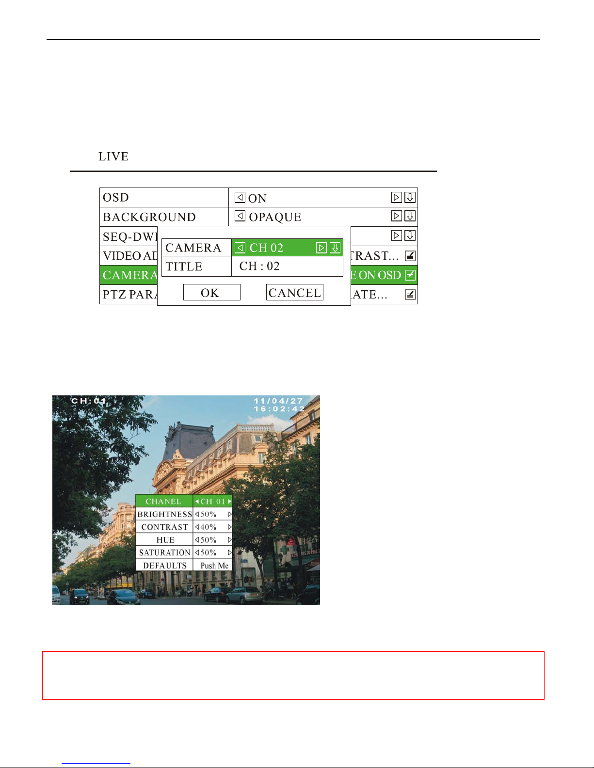
6.9.2 Rename the camera
1) Press
<MENU> to enter the DVR system menu, choose “LIVE” to enter its sub-menu, go to “OSD” and se t it
as “ON”,
2) Press
<MENU> to enter the DVR system menu, choose “LIVE” to enter its sub-menu, go to “CAMERA TITLE”
and press
<MENU> to enter, rename each camera by press <MENU> to get the “TEXT INPUT” dialog box:
3) After pressing <OK> to save the change, the new camera name will be shown on the OSD.
6.9.3 Video Adjustment
1) Press
<MENU> to enter the DVR system menu, choose “LIVE” to enter its sub-menu, go to “VIDEO
ADJUSTMENT” and press
<MENU> to enter, adjust the brightness, contrast, hue and saturation.
2) Press
<OK> to save and exit, or <ESC> to discard the change. If you want to resume to the defaulted
settings, just go to “DEFAULTS” and press
NOTE: With the consideration of PTZ control is few used in mobile application. The DVR system does
NOT support PTZ by defaulted. Please inform your sales person before mass production if you need
this function.
www.supercircuits.com MDVR21SD_RM
<MENU> or <OK> to confirm.
44
Page 45
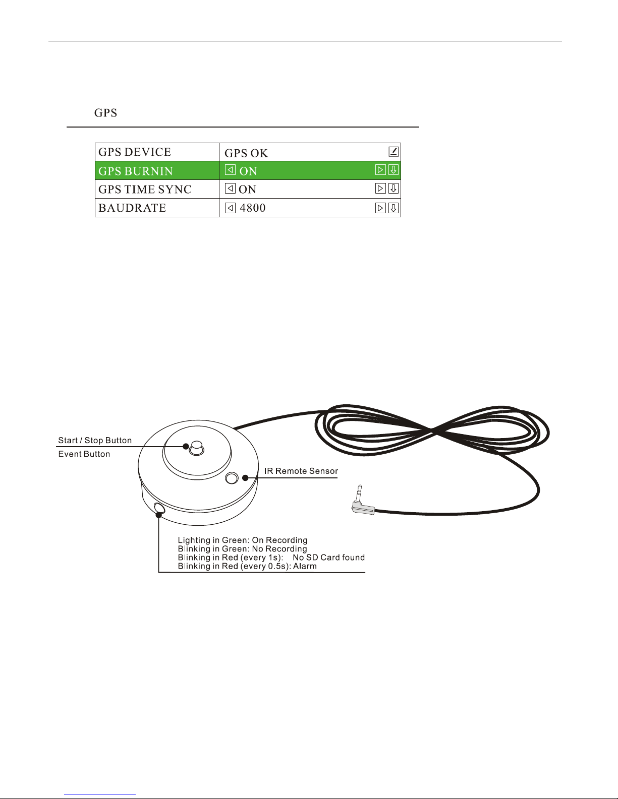
6.10 GPS Setting (Option)
Press<MENU> to enter the DVR system menu, choose “GPS” to enter its sub-menu.
a) The DVR system will check the GPS device automatically. If a GPS device is found to be connected, the
“GPS DEVICE” will show “GPS OK”; if no GPS device is found, it will show “GPS NONE”.
b) ”GPS BURNIN” can be set as “ON” or “OFF”. If it is set to be “ON”, the GPS coor dinate will be shown on the
screen; if it is set to be “OFF”, the coordinate will be hided.
c) “GPS TIME SYNC” can be set as “ON” or “OFF”. If it is set to be “ON”, it will synchronize the DVR system
time automatically (Recommended). If it is set to be “OFF”, it may not synchronize the time.
d) “BAUDRA TE” ref ers to GPS communication baudr ate. The def aulted baudr ate i s 4800. 2400, 9600, 19200,
38400, 57600, 115200 for options.
6.11 Event Button & Cable Setting (Option)
Two different applications of the Event Button & Cable:
1) Work as “Start/Stop Recording”.
2) Work as “Alarm Input”.
1) Press
2) Choose “AL ARM” and press
<MENU> by remote to enter the DVR system menu;
<OK> or <MENU> to enter its sub-menu;
3) Go to “POST EVENT RECORD” and set the time, press
www.supercircuits.com MDVR21SD_RM
<MENU> or <OK> to save and exit.
45
Page 46
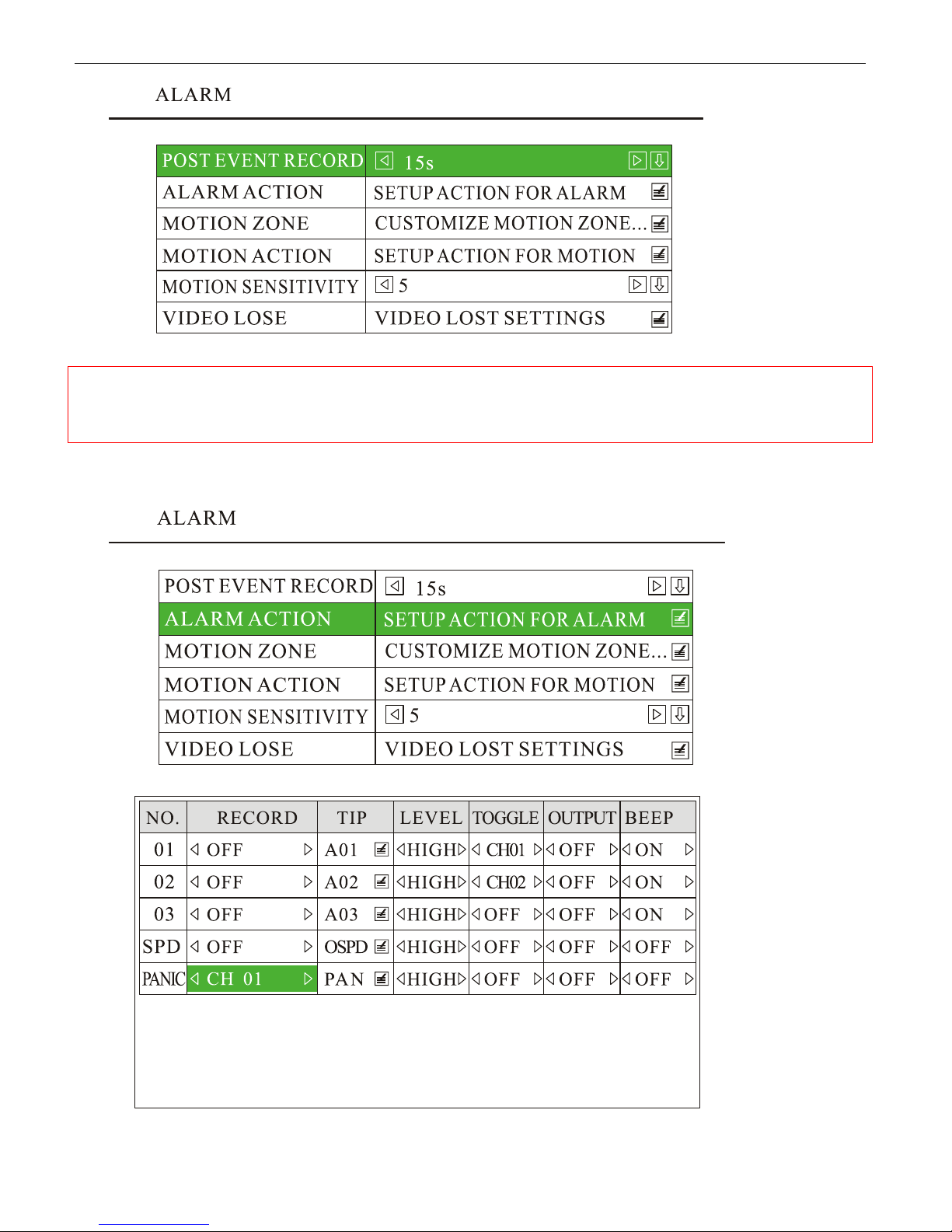
NOTE: The time you set will reflect to the recording time once Event Button is pressed. To take the
defaulted “15s” for an example, the alarm recording will last for 15 minutes since the Event Button is
pressed, then stop.
4) If you use Separate Mode for recording, press <MENU> to enter the DVR system menu, choose “ALARM” and
<MENU> to enter its sub-menu, go to “A LARM ACTION” to set the camera channel.
press
There are a total of 16 modes: OFF, CH 01, CH 02, CH 01+02, CH 03, CH 01+03, CH 02+03, 01+02+03, CH 04 ,
www.supercircuits.com MDVR21SD_RM
46
Page 47
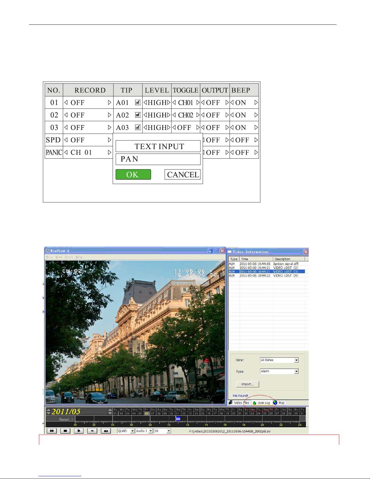
CH 01+04, CH 02+04, 01+02+04, CH 03+04, 01+03+04, 02+03+04 , ALL. The defaulted camera channel is CH
01. In Composite Mode, the quad mode will be regarded as “CH 01”.
5) You can also set up the text you want to display in the "TIP" of “ALARM ACTION”. The text you set will be
displayed if the event is triggered.
a) Connect the Event Cable to front panel of the DVR unit.
b) Press the Event button, the LED will flash in red, and you will hear buzzer if you set the “BEEP” as “ON”, it
means alarm recording is triggered.
c) The alarm recording is recorded in the log file. Please use the AVPlayer to view the log information.
NOTE: DVR system’s firmware for the two applications is different. Please tell your sales person
www.supercircuits.com MDVR21SD_RM
47
Page 48
the exact application before mass production.
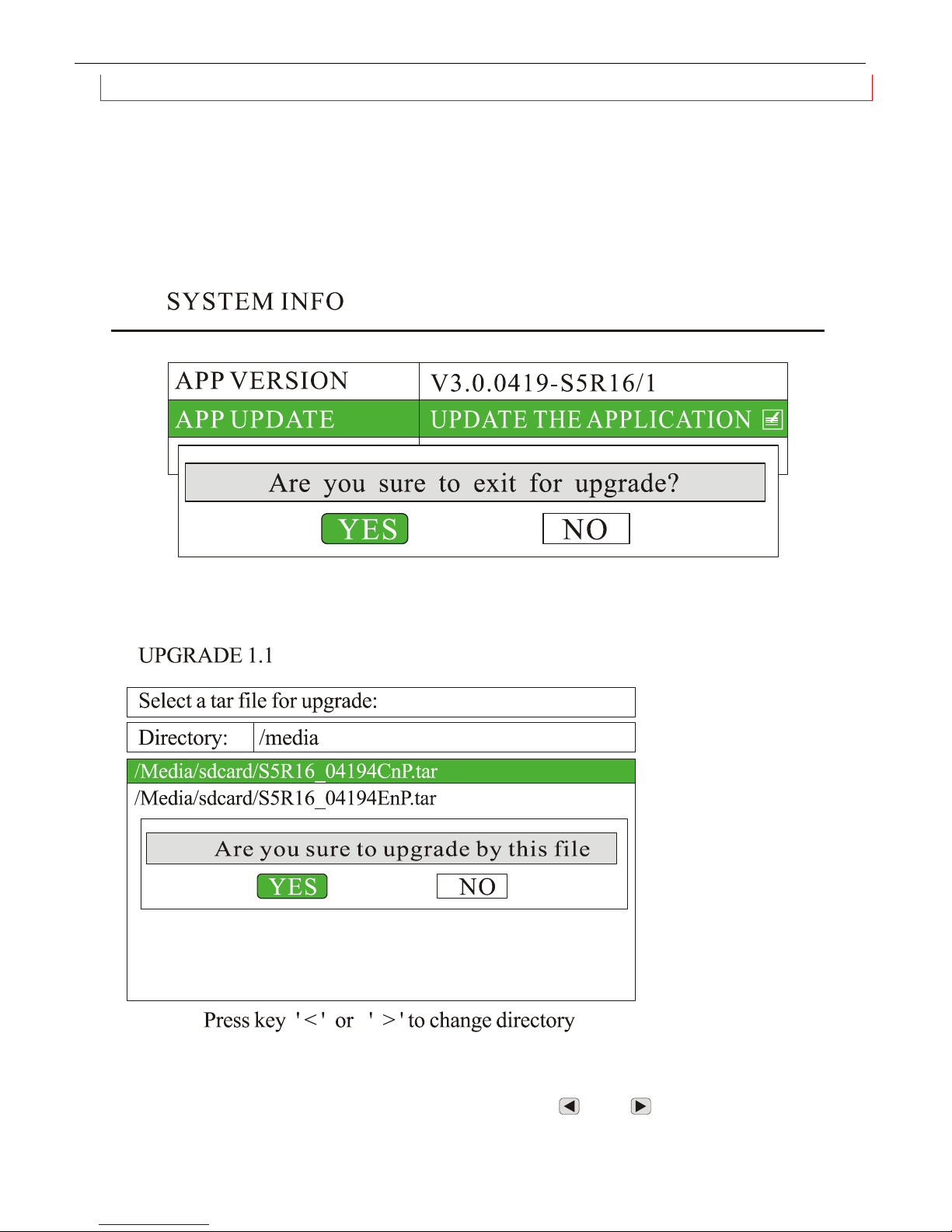
6.12 Firmware Update
1) Copy the update file to the root directory of SD card. The update file has the postfix of "tar".
2) Insert the SD car d into th e SD card slot on fr ont panel of the DVR system, pr ess
the DVR system menu.
3) Choose "SYSTEM" and press
4) Choose “SYSTEM INFO”, go to “APP UPDATE” and press
<MENU> to enter its sub-menu.
<MENU> to get ready for system update.
<MENU> by remote to enter
5) Press “YES” to exit the current program and continue with the upgrade.
6) Choose the update file you have copied to SD card. You can use “
there is more than one found. Press
www.supercircuits.com MDVR21SD_RM
” and “ ” to select the right directory if
<MENU> to continue.
48
Page 49
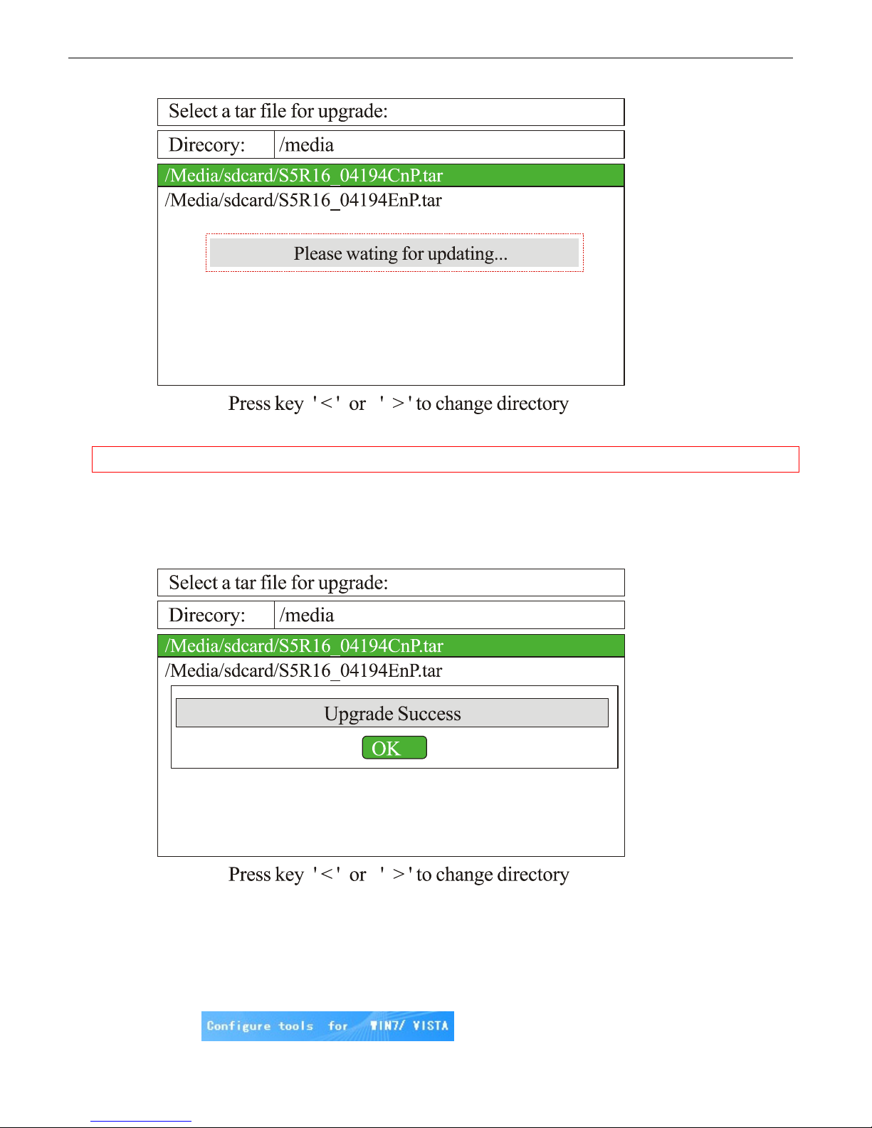
NOTE: Do not turn off the power while updating!
7) “Upgrade Success” will be shown up to remind you when update is successful, press
restart the application.
<MENU> by remote to
6.13 Using Wi-Fi Module (Option)
1) Debug the Wi-Fi module on PC
a) Connect Wi-Fi module to a PC’s USB and LAN ports;
b) Run “autorun.exe” included on CD with the Wi-Fi module. If the operation system of your PC is Win 7 or Vista,
please choose
www.supercircuits.com MDVR21SD_RM
; If the operation system is WinXP, please
49
Page 50
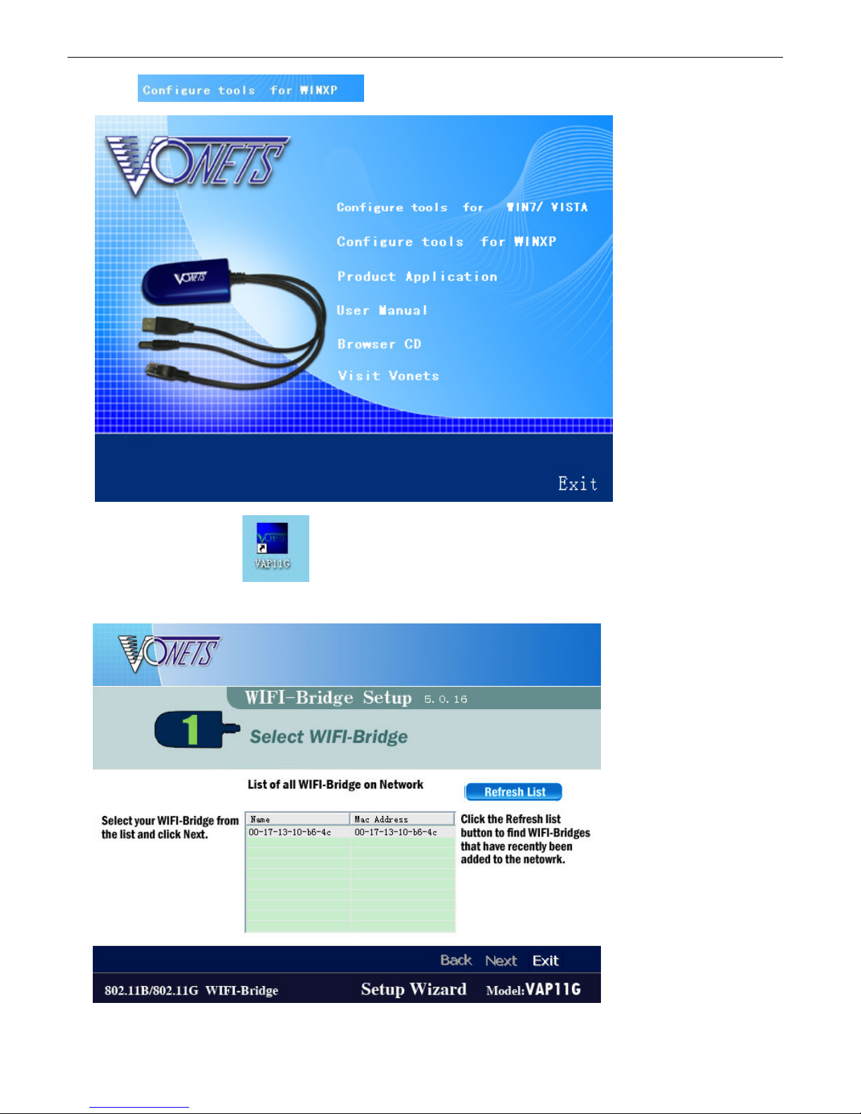
choose , then go with “NEXT” to finish the installation.
c) After that, you will find
bridge from the list and click “Next”:
on your desktop. Double-click this icon to run the software, select your WiFi
d) Select a wireless network to connect to:
www.supercircuits.com MDVR21SD_RM
50
Page 51
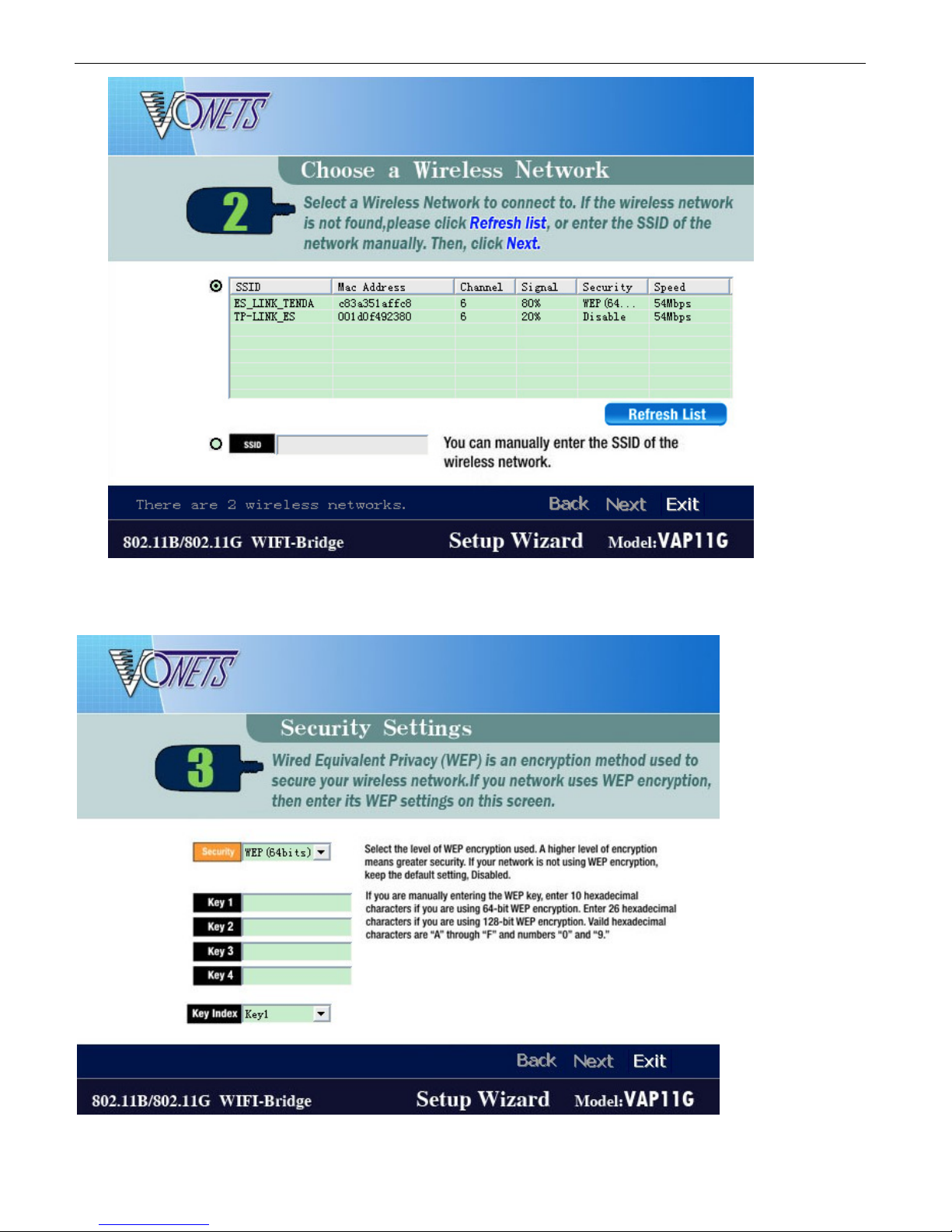
For an example, if you select the “ES_LINK_TENDA ” to connect to, press “Next” , input the ascii code of your password
in hex format. Y ou can look up the ascii code of your password in the ascii table (Appendix A). For an example, if your
password is "hello", you should input 68656c6c6f in “Key1”, then press “Next” to finish.
www.supercircuits.com MDVR21SD_RM
51
Page 52
e) If now your PC could access to internet through this Wi-Fi module, it means the Wi-Fi module has been debugged
well. You may remove the Wi-Fi module from your PC, and connect to DVR’s USB and LAN ports, power on the
DVR. Meanwhile, please find a PC within the same LAN, start to Ping the DVR, and see whether the DVR could
be connected to the same wireless network or not. Note: After connecting the Wi-Fi module to DVR, normally it
takes 6~7 minutes to ping through the PC. The defaulted IP address is 192.168.0.220 . If this is not with the
same network segment of router, you’re required to change the IP). If the DVR is ping through the computer, it
means it is connected to the same wireless network, and you can control it on software.
2) Use the client software to control the DVR:
a) Install supplier’s reviewing software into your PC. You will get three icons of “ViewPro”, “AVPlayer” and
“Record Calculator” on your PC desktop. “ViewPro” is used for live view, file download, set DVR remotely,
etc; “AVPlayer” is used for files playback.
b) Run the “ViewPro”. User Name or Password is not required, just press “Enter” to log in.
c) The software will refresh automatically and add new DVRs into the “DVR List”. If no DVR is found,
please check the network connection and refresh the list manually . When a DVR is found, please
double click to login in. By default, there is no password so you just click "Connect" to login to the
DVR. You can see the live video by double click the "channel01" or other channels.
d) Right click the DVR and choose "setup", you can set the parameter of the DVR.
e) Click "Remote File List" and choose the date, you can see the file list on the SD card.
f) Choose the file and right click, you can download the file manually.
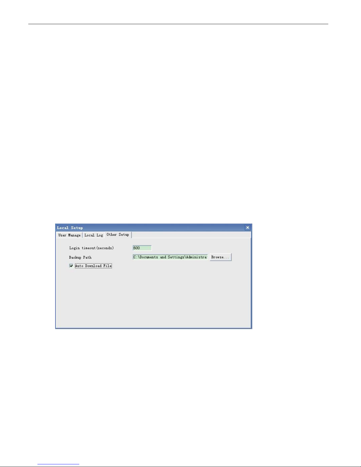
g) To download the file automatically, please choose the Menu “Setup””Local Setup” ”Other
Setup”, Click “Auto Download File”:
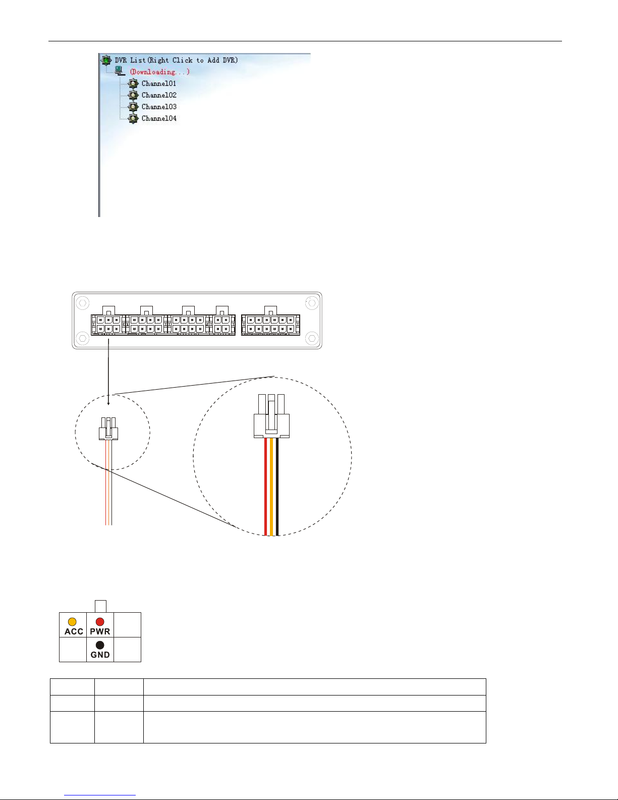
h) You can find the DVR in the “DVR List”, it will auto connect, and then auto download the record files.
The default download path is “my document”.
www.supercircuits.com MDVR21SD_RM
52
Page 53
7. Connection & Installation Cables
7.1 Power Supply Cable
Viewed from crimp side:
Mark Color Description
PWR RED “+” of power supply (you can connect to Battery “+”)
ACC YELLOW Ignition signal. Connect this wire to “+” of power supply if you don’t use
ignition to control the power.
www.supercircuits.com MDVR21SD_RM
53
Page 54
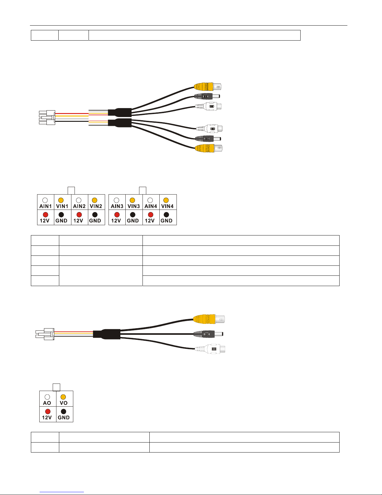
GND BLACK “-” of power supply (you can connect to Battery “-”)
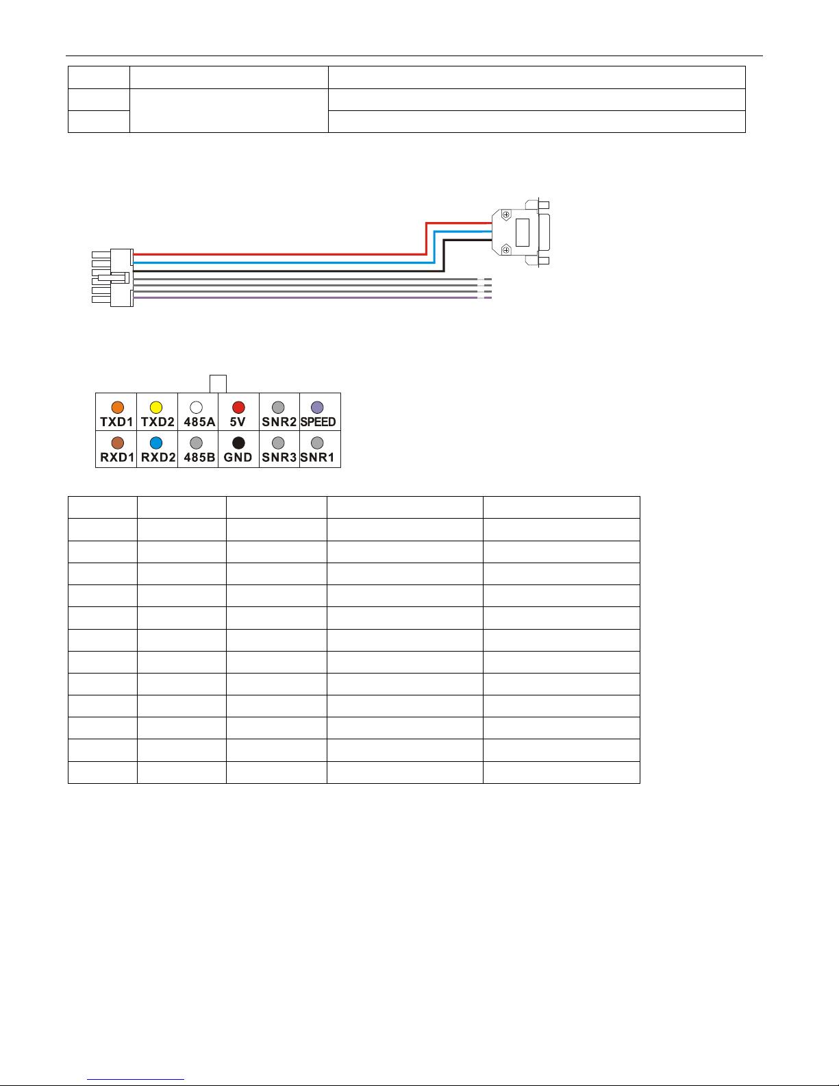
7.2 Video & Audio Input / Output Cable
1) Video& Audio Input Cable
Viewed from crimp side:
Mark Color Description
VI BNC Connector, in Yellow Video input
AI RCA Connector, in White Audio input
12V DC Connector, in Black Power output for camera(+12 VDC, Maximum curren t 1A)
GND Ground
2) Video & Audio Output Cable:
Viewed from crimp side:
Mark Color Description
VO BNC Connector, in Yellow Video output
www.supercircuits.com MDVR21SD_RM
54
Page 55
AO RCA Connector, in White Audio output
12V DC Connector, in Black Power output for camera(+12 VDC, Maximum current 1A)
GND Ground
7.3 Sensor Harness
Pin No. Description Color Description GPS Connector
1 TXD1 Vacant TXD, COM1, (GPS)
2 TXD2 Vacant TXD, COM2
3 485A Vacant RS485 A, (PTZ)
4 5.0V Red +5 VDC Pin 9
5 SNR2 Grey Sensor 2
6 SPEED Violet Speed sensor
7 RXD1 Vacant RXD, COM1, (GPS)
8 RXD2 Blue RXD, COM2 Pin 3
9 485B Vacant RX485 B, (PTZ)
10 GND Black Ground Pin 5
11 SNR3 Grey Sensor 3
12 SNR1 Grey Sensor 1
3) GPS connector (RS232 COM1)
www.supercircuits.com MDVR21SD_RM
55
Page 56
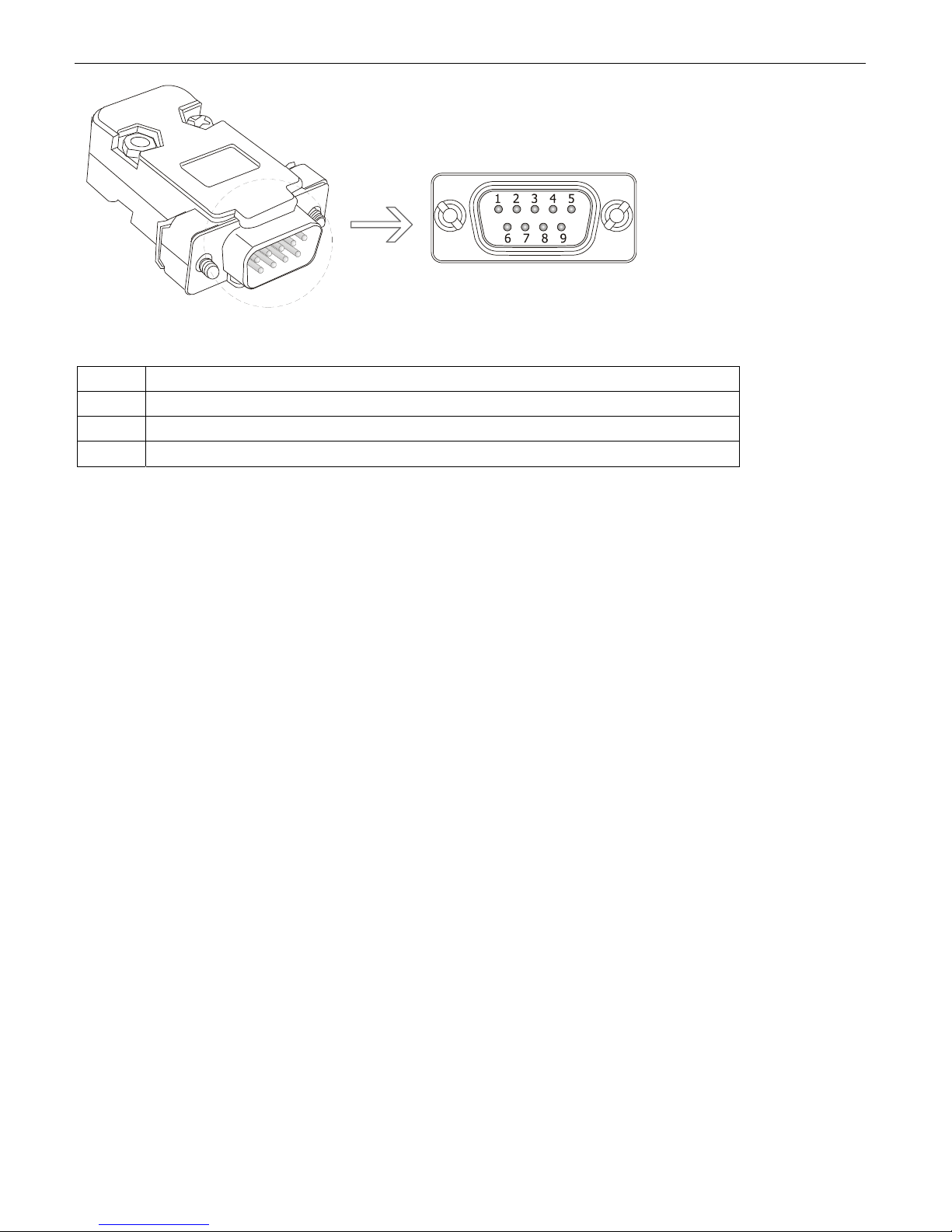
PIN Description
3 RXD2: Data receive
5 GND: Ground
9 +5V DC: Power output
www.supercircuits.com MDVR21SD_RM
56
Page 57
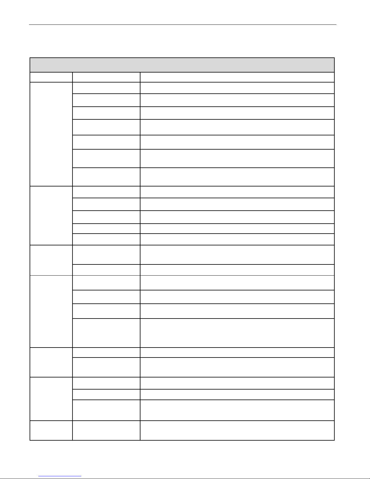
8. Specification
SPECIFICATION
ITEM MDVR21SD
VIDEO INPUT 4 channels
VIDEO OUTPUT 1 channel, 1.0V, p-p, 75Ω, BNC
VIDEO FORMAT Support PAL/NTSC
VIDEO COMPRESSION H.264 High Profile
VIDEO
RECORD RESOLUTION 1280x1024(PAL) / 1248x832(NTSC)
FRAME RATE 100fps(D1 PAL) / 120fps(D1 NTSC)
VIDEO BITRATE 1.98Mbps ~ 4.5Mbps, 4 level video quality
AUDIO INPUT 4 channels
AUDIO
STORAGE
INTERFACE
SOFTWARE
AUDIO INPUT FORMAT 20KΩ, RCA
AUDIO OUTPUT 1 channel, 500Ω, RCA
AUDIO LEVEL 1V ~2V, p-p
AUDIO COMPRESSION G.711
STORAGE SD card, external USB device (memory stick or hard drive)
FILE FORMAT AVI
SENSORS 1 speed sensor, 1 ignition sensor, 3 sensors for brake, return etc.
COM PORT 2 RS232 port, 1 RS485 port
NETWORK RJ45, 10M/100M Ethernet
Support GPS receiver (optional), Synchronize the DVR system time with
GPS
GPS automatically, can record GPS information along with video and
audio. GPS data format: NEMA0183, Baud rate: 4800bps
PLAYER Specially designed player for the DVR
THIRD PARTY
SOFTWARE
Windows Media Player(Ver 11.0 or above), VLC Media Player(Ver1.0.0
or above)
INPUT POWER From +8VDC to +32VDC
POWER
POWER OUTPUT DC, [email protected], +5V@1A
POWER COMSUMPTION
OTHER
www.supercircuits.com MDVR21SD_RM
WORKING
TEMPRETURE
Working power: <5W, Strand by power: 0.1W (exclude camera, SD
card, monitor)
From -30 ~ +60
57
Page 58
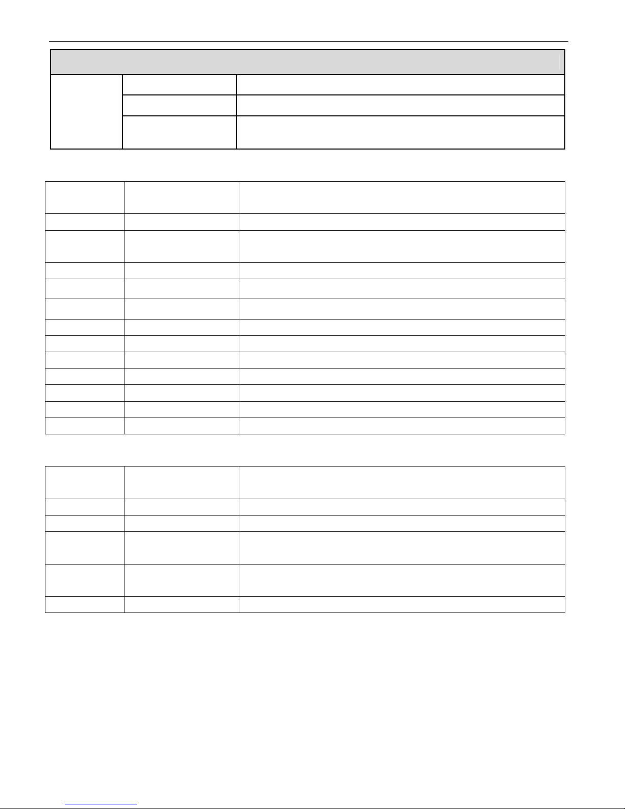
SPECIFICATION
SIZE 12cm X 9cm X 2cm (4.75" x 3.5" x 0.8")
WEIGHT 0.3KG
PACKAGE SIZE AND
WEIGHT
21cm X 14cm X 7.5cm (8.3” x 5.5” x 3.0”), 0.63KG
9. List of Standard Accessories
Item Description Quantity
1 SD Video Recorder 1 pc
2 Tamperproof &Lock
Case
3 Lock case key 2 pcs
4 AV input cable 4 pcs for four channel MDVR21SD
5 AV output cable 1 pc
6 Signal cables 1 pc
7 Power cable 1 pc
8 Remote Controller 1 pc
9 Fuse box 1 pc
10 1.5A fuse 2 pcs
11 Screws 4 pcs
12 User’s Manual 1 pc
Options:
1 pc
Item Description Quantity
1 External GPS Receiver 1 pc
2 Event Button & Cable 1 pc
3 Extension Cable (3m,
5m, 10m Option)
4 SD Card (16GB, 32GB,
64GB)
5 SD Card Reader 1pc
www.supercircuits.com MDVR21SD_RM
4 pcs for four channel MDVR21SD
1pc
58
Page 59

10. Trouble Shooting.
1. Q : After connecting the DVR power, no video output, No.1 and No.2 indicators
lights on panel flashing alternately.
A: The No.1 and No.2 indicator light is “Power” and “Run” . If the 2 indicators lights are flashing
alternatively , the DVR missed the ignition signal, please check if the yellow line of the input power
lines has connected with the power positive level, or if it’s the same as the setting of the effective
electrical level in menu settings. (The factory default settings set the high level effective,that is,
it is effective when the yellow ignition signal line is connecting with the power positive level .)
2. Q: As SD cards’ capacity limited, how to make the videos’ time expand to meet the
requirements of the customers?
A: Reduce the video frame rate, video quality and record by Composite Mode.
1. Set the Channel Mode in the "Video Settings" menu to Composite Record (see 3.5);
2, Enter the "Video Parameters settings" menu, select a lower vide o quality, while reduce the
frame rate to 12 frames / sec or less. Generally, it can expand the recording time to 4 to 10 times
longer or more by using the above method.
3. Q: when using the DVR, ScreenTip appears "read only error ".
A: Please check if the SD card is write-protected, if so, please move the picks to the non - write
protected.
4. Q: What is a high level, what is low level?
A: Generally, there are two electrical levels in the car, the power and the ground. Automotiv e
power voltage with 12V and 24V, we generally call it high level, not the specific voltage value.
Ground of Vehicle is the ref erence level, accurately is battery negative electrode. We generally call
it low level. For cars with negative switch control (the main switch cut off the connection of the
battery cathode and car chassis ground), the chassis ground connects to the battery anode
through a certain resistance, the chassis ground is not a reference ground anymore. Please see
the Appendix in the back, including the potential analysis diagram against cars with negative
switch control.
5. Q: Respectively, what’s the voltage reference range of the high and low level in
the DVR?
A: The voltage range of low level is DC 0V~3V, the high level is DC6V~32V.
6. Q: Why doesn't the DVR remote control work?
A: Please make sure the battery in the remote control is still good, or try to change a new battery .
And make sure aiming the remote control at infrared receptor window on the front panel of DVR.
7. Q: SD cards or hard drives are OK, but the video recording doesn't work, what
should I do?
A: Please make sure if the default setting of Record Mode is changed from "Automatic" to" Off ",
and whether to modify the DVR to scheduled record mode and the current time is not within the
www.supercircuits.com MDVR21SD_RM
59
Page 60

time period you set.
8. Q: Do your SD Card DVR support the capacity of 64G and above SDXC card?
A: The DVR support the capacities of 64G and above SDXC cards, but currently, DVR doesn’t
support for ExFA T file system completely , we suggest that you format the SDXC card to F A T32 file
system under Windows system before using. You can also download free version “Partition
Manager” or other partition software from the Internet, which can make the process faster and
simpler.
9. Q: when the SD card inserted the DVR for recording, live images or playback
visual will come to a frequent halt.
A: Please make sure that if your SD card or USB’s writing speed is enough. When the recording
medium’s writing speed is not e nough, it w ill af f ect the continuit y of liv e vi deo and the r eal-time
recorded video. Generally the SD card DVR can directly support two kinds of media:
1). SD card. With good writing speed and quality, there are Kingston, T ranscent etc. brands on
the market, It is more reliable for its conventional speed values of Class x and op eration, it will not
pause even with the highest record data rate on this machine. While other bra nds’ SD car d with
the uneven quality and serious counterfeit, customers come to meet this problem usually, the
fault disappears after replacing the SD card.
2). USB disk. Because of the cost sensitive reasons, most of USB disks sold on the market are
the products of the USB1.1.Their speed can not meet the data rate of the requirements of the
DVR. Please replace USB2.0 products for the faster speed.
10. Q: Do internal real time clock of the DVR maintained by batteries? If so, how
long will it last?
A: Rechargeable batteries are used for DVR internal real time clock. If the battery is fully
charged and DVR is completely disconnected from the power supply, internal real time clock can
probably last for 1 month.
11. Q: How to take out the SD card from the DVR safely?
A: It’s similar to use a SD card or USB disk on the computer, stop the file opera tion before the
extraction, so as to ensure that the internal files of SD card or USB disk will not be destroyed or
lost. This SD DVR provides a simple and safe wa y to eject the SD card: before eject the SD card,
please press a small button on the right of the SD card, when you see the yellow indicator light
goes OFF, you can eject your SD card safely.
12. Q: what do the 5 indicator lights representative on the panel of the DVR?
A: The first and second green indicator lights on the panel:
Power indicator light Running indicator light Description
Light-on Flashing DVR on and running
Flashing alternately with Flashing alternately with power No ignition signal, DVR off
www.supercircuits.com MDVR21SD_RM
60
Page 61

Power indicator light Running indicator light Description
running indicator light indicator light
Flashing simultaneously with
running indicator light
Flashing (slow flash)
Flashing simultaneously with
power indicator light
Light-off DVR off. At this point, press”
Ignition signal disappears, DVR
countdown running. After the time
setting in the" ignition delay ", DVR
off automatically.
Power” button on the remote
control, DVR on.
The third red indicator light on the panel:
Alarm indicator light(red light)
Description
Light-on DVR with alarm (such as over speed)
Light-off DVR without alarm
The fourth red indicator light on the panel is SD card operation indica tor light, this indicator light
will shine timely when DVR recording or playing.
The fifth yellow indicator light on the panel is SD card recording indicator light, if this light on,
it means DVR is recording.
13. Q: what kind of player software should use to play back video slots in SD card on
the PC? Why some of them don’t play normally?
A: The SD DVR recording files is a standard AVI format, video stream compression standard
is senior H. 264.
1. SD DVR has its own player software, including many special additional feature, such as
playing continuously, fast forward playing, and other quickly locating recording and playing.
2. The recorded f iles also support general players. Such as VLC (version 1.0.0 and above,
free open source software, can download from the internet), Media Player Classic(version 2009
Build: 3.9. above). Older Storm Audio can only support for video of 720x576 - resolution, when
playing high resolution (1280x1024) recorded video file of Composite Mode, it can't display all the
images, images on the right and below the video will be cut-off.
14. Q: How to upgrade the SD DVR program?
A: 1.Copy the update package (Suffix ".tar" files) to the root directory of SD card (or USB disk).
Be careful not to extract.
2. Insert the SD card (USB disk) to DVR, after the machine detects the SD card, press menu
to upgrade: System settings -> system information (version, upgrade etc.) -> upgrade
-> upgrade your current application -> select the upgrade file -> OK
(Note: press the menu key to enter the next level of menu items. Normally you can
complete the whole upgrade operation by using the menu key only.)
15. Q: Do your DVRs have RS485 control PTZ functions?
A: For very few of car application using PTZ contr ol, mobile DVR factory default is without the
www.supercircuits.com MDVR21SD_RM
61
Page 62

RS485 control PTZ functions. If you do need PTZ control function, please contact sales when
ordering.
16. Q: I bought the mobile DVR with PTZ control function, but it has no response
after PTZ connecting.
A: After you have confirmed your machine already has PTZ contr ol f unction, you m ay t est y our
control functions in accordance with the following:
1, Exchange the two lines of 485A and 485B, to see if they are connected wrong;
2, Confirm if the PTZ Protocol is right;
3, Confirm if the PTZ Address is right, our default is 1, trying to adjust to 0 or 2; generally
the PTZ address code is 1. The address code needs to be changed when multiple PTZ devices
connected. In addition, the address of each PTZ device cannot be duplicated, if you have 4 PTZ
devices, you can respectively set them to address 1, address 2, addresse3 and address 4.
17. Q: what is the difference of Separate Recording Mode and Composite Recording
Mode?
A : Separate Recording Mode, that is, the DVR compress each of front-end camera's
image and audio separately , if it is a 4 - channel DVR, yo u will have 4 real-time D1 image AVI files,
which is recorded on the SD card or USB disk at the same time.
Composite Recording Mode, that is, to composite multiple front-end camera images into
a high - definition image (such as 1280x1024), and then compress the image w ith video encoder,
at one point in time there has been only 1 high - definition AVI files recorded on SD card or USB
disk.
Recording by Separate Mode can extr act AVI file of each camera separately, but we can get
recorded file of combination image with 4 cameras by Composite Mode.
The default recording mode of the SD DVR is the Composite recording Mode, its advantages are
high-definition, storage space saving and convenient playing.
18. Q: How long will my SD card of 32GB record?
A: we have provided recording volume calculator software on the accessory CD, which can
run on a PC. Or in the record settings of the host, select the different settings, such as quality,
frame rate, it will show the total recording time of your c urrent storage module below the screen.
Generally speaking, recording time not only relates with picture quality, frame rate, but also
relates with frequency of scenery changing in front of the camera lens. For some static image, the
real recording time will be considerably longer than the calculated time.
19. Q: Why can't I use VLC or other software to see the real time image through the
network?
A: The SD DVR turns off the network function by default, if y ou need network, please set the
"Network" to "on" in the "Record - Video Parameters ".
20. Q: Why is the bottom section of the screen with no image or video corruption?
A: Firstly , mak e sure the DVR’ s video system and camer a system are the same, for example,
www.supercircuits.com MDVR21SD_RM
62
Page 63

it will occur when the DVR settings is P AL system, while the camer a is NT SC system. Conv ersely,
if the DVR is set with NTSC system, scrolled fault images also occur when connecting a camera
with PAL system.
21. Q: when retrieving record files on the machine, only find the record files of
channel 1, how to find the files of the other channels?
A: Press the <left> or <right> keys on the remote control to switch other channels to
retrieve record f iles. On the top right of the screen will display which channel the current f ile
belongs to.
22. Q: what is “Power OFF Delay”?
A: Users who need to install DVR often want the DVR to record the images inside and outside
the car for a while after the driver turn the engine off. That is, DVR cannot be turned off after
engine is shutdown, it should be off after recor d continuously for the specified period of time. This
time is called “Power OFF Delay” time, such as 30 seconds. Y ou can set the time you need on "Car
Settings – Power Off Delay ".
When the users who need “Power OFF Delay” function, the positive lev el of the DVR and the
ground should be connected directly (through the fuse) to the cathode and anode of the car
battery, at the same time attach car ignition signal line to the ACC of the car.
Of course, the time of “Power OFF Delay” cannot be set too long, because after the engine
shutdown, mobile DVR entirely depend on the power of the car battery to work, we should
prevent the vehicle can’t start correctly next time if the mobile DVR drained the energy of the car
battery.
23. Q: Why does DVR keep alarm when I set the motion detection, even if the image
moving is not obvious?
A: First, please make sure that if the sensitivity settings of the motion detection are correct,
sensitivity is divided into 9 levels. The ninth level is the highest sensitivity; the f irst level is the
lowest sensitivity.
Second, make sure that if your camera system (PAL system or NTSC system) match the
stroboscopic lighting devices such as fluorescent lights. PAL system is 50Hz system, NTSC system
is 60Hz system, and there are also two kinds of working frequency of power grid: 50Hz and 60Hz.
if a PAL camera of 50Hz work under the fluorescent lights driven by the power grid of 60HZ,
images will appear frequency difference flashing of 10Hz, this will led system to think scenery
brightness is changing continuously, and motion detection alarm is based on the changes of
scenery brightness to work, this will triggered motion detection alarm. Conversely, a false alarm
will also occur when a camera of 60Hz works under the fluorescent lights driven by the pow er grid
of 50HZ.
24. Q: What does the indicator light mean on the wire control L25?
A: The indicator light on the wire control is double color light, red and green. See the
following form for their state.
www.supercircuits.com MDVR21SD_RM
63
Page 64

State of green
light
One slow flash
every three
seconds
One flash every
second
lighting
One flash every 0.5
seconds
Meaning
System start
System is normal but
no record
System recording
normal
No definition
State of green
light
Slow flash every
three seconds
One flash every
second
lighting No definition
One flash every 0.5
seconds
Meaning
Communication of
wire control is not
normal
No memory device
System alarm
indicator (the same as
buzzer)
www.supercircuits.com MDVR21SD_RM
64
 Loading...