

Page 1
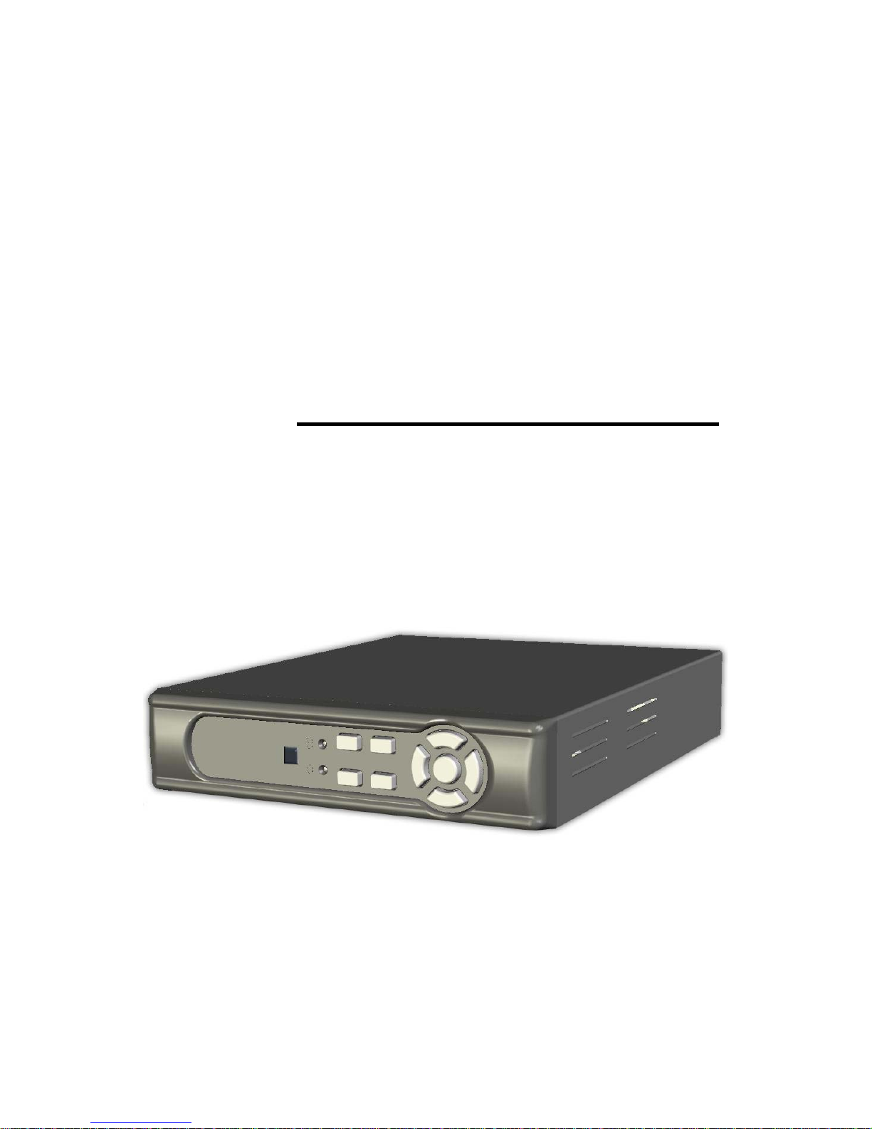
USER MANUAL
4CH MJPEG DVR
○
9
VER.:1.0, CD
Page 2

1
Contents
1. SAFETY PRECAUTIONS.................................................................................. 2
2. INTRODUCTION............................................................................................... 3
2.1 Product Introduction................................................................................ 3
2.2 Application .............................................................................................. 3
3. FEATURES ......................................................................................................... 4
4. PACKING LIST .................................................................................................. 5
5. NAME and FUNCTION of EACH PART................................................................... 6
5.1 Front Panel............................................................................................... 6
5.2 Rear Panel................................................................................................ 7
6. INSTALLATION................................................................................................. 8
6.1 System Configuration.............................................................................. 8
6.2 Hard Disk Installation ............................................................................. 9
7. OPERATING PROCEDURE ............................................................................ 11
7.1 Power On............................................................................................... 11
7.2 Monitoring Mode .................................................................................. 11
7.3 Record Mode ......................................................................................... 12
7.4 Playback Mode ...................................................................................... 13
8. SYSTEM SETUP .............................................................................................. 14
8.1 Menu Setup............................................................................................ 14
8.2 Camera Setup ........................................................................................ 16
8.3 Record Setup ......................................................................................... 17
8.3.1 Record Frame ..................................................................................... 18
8.3.2 Record Schedule................................................................................. 19
8.4 Motion Detection Setup......................................................................... 20
8.4.1 Motion Area ....................................................................................... 21
8.5 Screen Setup .......................................................................................... 22
8.5.1 Video Adjustment............................................................................... 23
8.6 Audio Setup........................................................................................... 24
8.7 System Setup ......................................................................................... 25
8.7.1 Hard Disk ........................................................................................... 26
8.7.1.1 Format HDD.................................................................................... 28
8.7.2 Password Setup................................................................................... 31
8.7.2.1 Password Change ............................................................................ 32
8.7.3 Time Set ............................................................................................. 35
8.7.4 Event List............................................................................................ 36
8.7.5 Software Update ................................................................................. 37
8.8 Exit ........................................................................................................ 41
8.9 Backup via USB Memory Stick ............................................................ 42
9. REMOTE CONTROL (option)......................................................................... 45
Remote Control ID ...................................................................................... 45
10. HDD Player Software Description .................................................................. 46
11. TROUBLESHOOTING .................................................................................. 59
12. SPECIFICATION............................................................................................ 60
The author assumes no responsibility for any errors or omissions that may appear in this
document nor does it make a commitment to update the information herein.
Page 3
2
1. SAFETY PRECAUTIONS
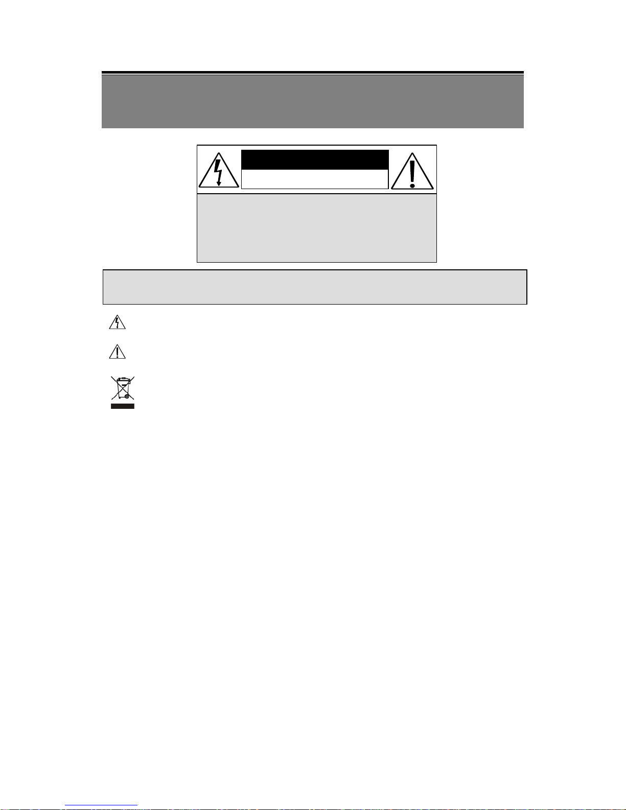
WARNING: This symbol is intended to alert the user to the presence of un-insulated
“ dangerous voltage”.
CAUTION: This symbol is intended to alert the user to presence of important operating
and maintenance (Servicing) instructions in the literature accompanying the appliance.
Disposal of Old Electrical & Electronic Equipment (Applicable in the European
Union and other European countries with separate collection systems).
This symbol on the product or on its packaging indicates that this product shall not be treated as
household waste. Instead it shall be handed over to the applicable collection point for the
recycling of electrical and electronic equipment. By ensuring this product is disposed of
correctly, you will help prevent potential negative consequences for the environment and
human health, which could otherwise be caused by inappropriate waste handling of this product.
The recycling of materials will help to conserve natural resources. For more detailed
information about recycling of this product, please contact your local city office , your
household waste disposal service or the shop where you purchased the product.
The power cord is the main power connection. Therefore, constantly plug and unplug of the
power cord might result in malfunction of the product.
Do not install the product in an environment where the humidity is high.
Unless the product is waterproof or weatherproof, otherwise it can cause the image quality to be
poor..
Do not drop the product or subject them to physical shocks.
Except for vandal-proof or shockproof product. Otherwise it will result malfunctions to occur.
Never keep the product to direct strong light.
It can damage the product.
Do not spill liquid of any kind on the product.
If it gets wet, wipe it dry immediately. Alcohol or beverage can contain minerals that
corrode the electronic components.
Do not expose to extreme temperatures.
Use the product at temperatures within 5 ~ 40 .℃℃
It is advised to read the Safety Precaution Guide through carefully before operating the
product, to prevent any possible danger.
CAUTION
RISK OF ELECTRIC SHOCK.
DO NOT OPEN!
CAUTION :
TO REDUCE THE RISK OF ELECTRICAL SHOCK,
DO NOT OPEN COVERS (OR BACK).
NO USER SERVICEABLE PARTS INSIDE.
REFER SERVICING TO QUALIFIED
SERVICE PERSONNEL.
Page 4

3
2. INTRODUCTION
2.1 Product Introduction
The product is perfect for office safety, personnel home security, public
environments, industry surveillance, school, and so on. Quick and simple installation
is the best choice for your own ultimate protection.
The sate-of-art 4-channel M-JPEG digital video recording that replaces the old
conventional video recorders and supports Chinese user interface. Using time and
event to playback recorded materials, efficient live recording and playback function,
supports SATA hard disk. The administrator can freely setup administrator password
to prevent any user randomly changing the setup.
2.2 Application
z Security:
ATM (auto teller machine), bank, gas station, shop and parking lot.
z Factory/ Office:
Factory, warehouse, remote technology support, conference room, and outdoor
parking lot.
z Education/ Military/ Government Organization:
Important facilities, important areas, rapid transit system, and railroad safety.
z Recreation/ Activities:
Sports and news broadcast.
z Home:
Elevator, doorway, community safety, and hotels.
z Hospital/ Kindergarten:
Hospital and isolated ward, home for the aged, kindergarten, and baby nourishing
center.
Page 5

4
3. FEATURES
z Video system auto detection
Auto detects video input (NTSC/ PAL) and supports combine use of color and b/w
cameras.
z Supports high quality digital video recording
Adopts M-JPEG compression technology (NTSC: 60 IPS/ PAL: 50 IPS).
z Video Size
Video Resolution
• NTSC: 640x 224
• PAL: 640x 272
Monitoring Resolution
• NTSC: 720x 480
• PAL: 720x 576
z 1CH audio recording and playback function.
z Replaces the conventional VCR.
Stores video on hard disks instead of VCR tapes, with large disk capacity, there is
no need to replace the recording medium.
z Built-in motion detection function.
Motion detection and sensitivity rate may be setup under motion detection
function.
z High efficient event recording, saving storage capacity.
Motion detection function enables recording only when system detects motion,
thus increases the amount of time available for recording.
z Easy access to the desired record.
Time & date search supports instant retrieval of images and alarm event search
makes searching simpler.
Page 6
5
4. PACKING LIST
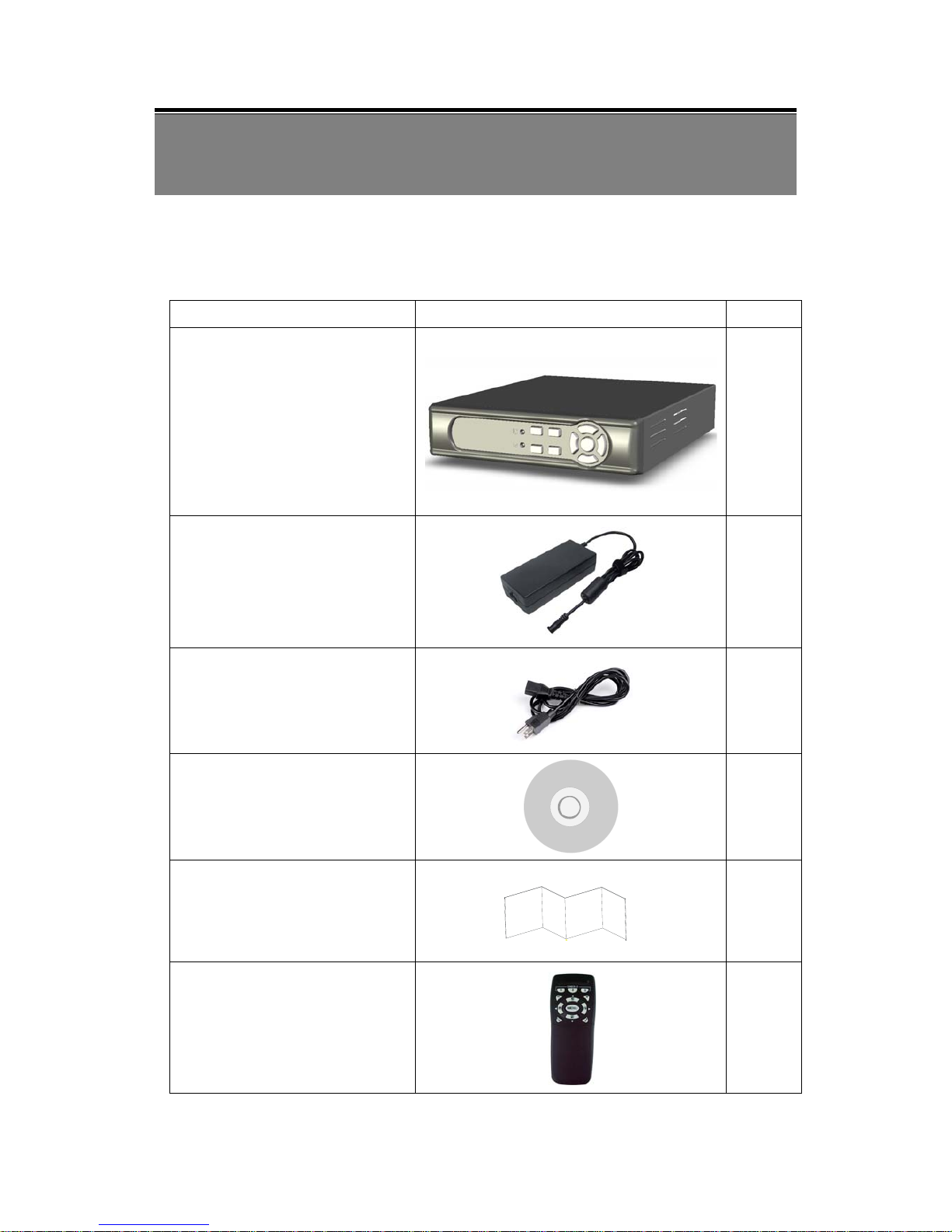
Check to make sure all of the items shown below are included in your product
package. If something is missing, contact your dealer as soon as possible.
Item Description Item Picture
QTY
DVR
1
DC 12V/ 2.5A Power Adapter
Input: AC 100~240V
Output: DC 12V/ 2.5A
1
Power Cord
1
CD-ROM
1
Quick Installation Guide
1
Remote Control
1
Page 7
6
5. NAME and FUNCTION of EACH PART
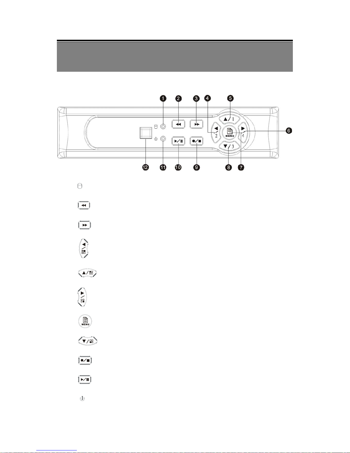
5.1 Front Panel
(1) : Record LED indicator.
(2) : Rewind button.
(3) : Fast forward button/ Enter Selection.
(4) : Left direction button / CH 2 screen display
(5) : Up direction button / CH 1 screen display
(6) : Right direction button / CH 4 screen display
(7) : Enter / Exit Menu
(8) : Down direction button / CH 3 screen display
(9) : Record / Stop button
(10)
: Play / Pause button
(11)
: Power LED indicator
Page 8
7
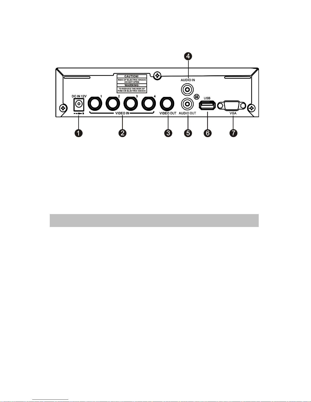
5.2 Rear Panel
(1) DC 12V [Power Input terminal]: power socket.
(2) Video Input [VIDEO IN]: Connect to cameras.
(3) Video Output [VIDEO OUT]: Connect to the monitor.
(4) Audio Input [AUDIO IN] : RCA input port for an audio signal
(5) Audio Output [AUDIO OUTPUT] : RCA output port for an audio signal
(6) USB: Connect to external USB storage device (Plug and Play).
(7) VGA: VGA signal output.
NOTE: For VGA function, you need to separately purchase a DVR with VGA function.
Page 9
8
6. INSTALLATION
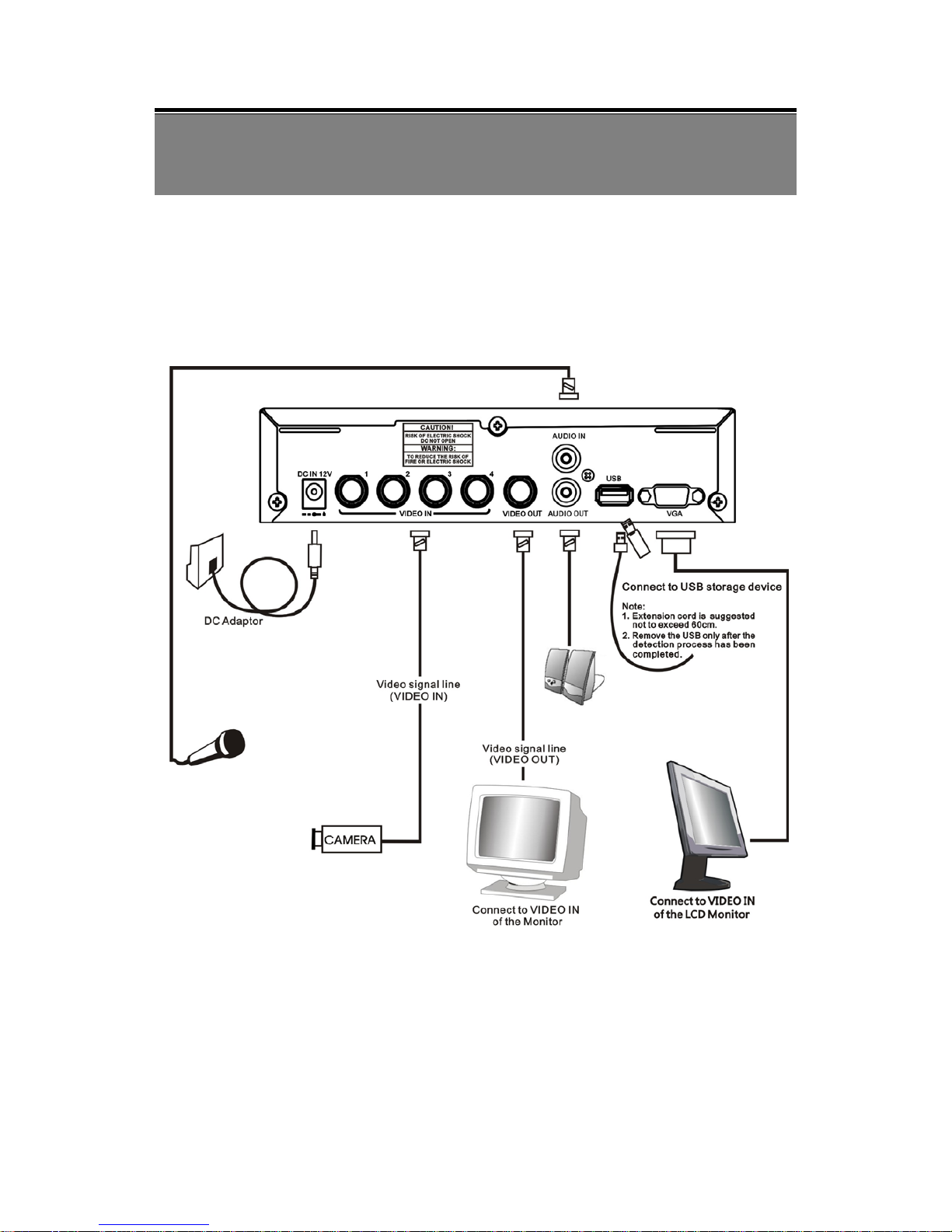
6.1 System Configuration
Please setup the connection by following the illustration shown below: Connect camera,
monitor and power to enter monitoring mode. To backup images, connect the USB storage
device. The DVR also supports VGA video output.
Page 10
9
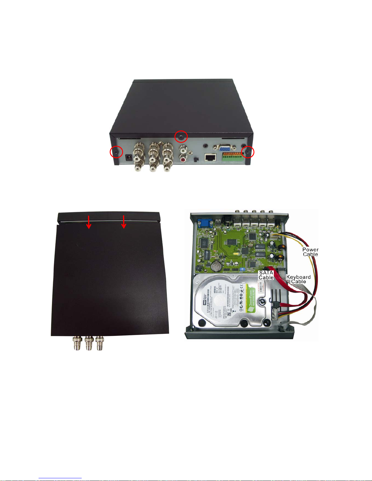
6.2 Hard Disk Installation
Step 1: Remove the 3 screws from DVR as cycled below (PIC 1).
(PIC 1)
Step 2: Remove the front cover from DVR as indicated by the arrow (PIC 2).
(PIC 2)
Page 11
10
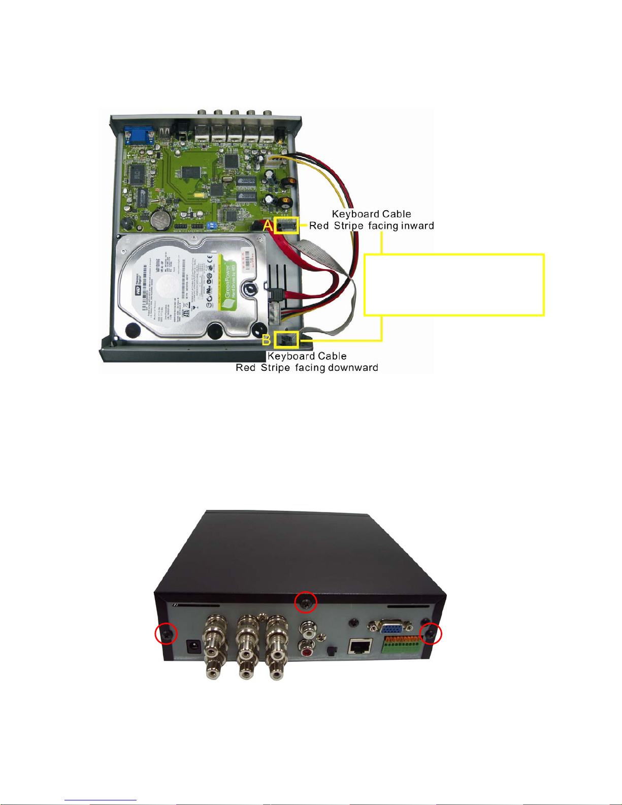
Step 3: Place the HDD on the HDD plate and connect the power, SATA cable and the
keyboard cable in place (PIC 3).
(PIC 3)
NOTE: Connect one end of the ribbon cable to the connector on the main board (A) and
the other to a keyboard socket (B). Both ends of the cable should always be
connected. The Red stripe on the cable MUST be aligned with Pin 1 on both
side of the cable (cable as shown above).
Step 4: Secure the screws back in position, as indicated below (PIC 4).
(PIC 4)
NOTE!
It’s very important to align the RED
Stripe with Pin 1. Visually check to make
sure all the pins are properly mated.
Page 12
11
7. OPERATING PROCEDURE
7.1 Power On
After power on, DVR will auto-detect its peripherals (self-testing, auto detects the hard
disk, and etc.).
The system will detect the video input and judge whether the video system is
NTSC or PAL. When video input is unable to be detected (VIDEO LOSS), the system
will send out an alarm (it will not affect the actual recording, but when all (1CH-4CH)
video images disappears, the DVR will stop recording).
7.2 Monitoring Mode
This mode is a default status after power on. Under this mode, system supports
live view for monitoring. Press《 》button, the system enters the manual record
mode, press《 》button to start playback, press《 》button to enter the menu
setup display. During playback, press《 》button to return to monitoring mode.
Under Manual Record mode press《 》button to stop recording and return to
monitoring mode or press《 》button under main menu also returns to monitoring
mode.
During playback, press Stop button to return to monitoring mode or press《 》
button to fast forward: FF1 ( ), FF2 ( ) or FF3 ( ) and press《 》to
rewind playback.
To restore default value: Enter MENU and select item EXIT, proceed “Load Setup
Default” to return to factory default settings (Default Password : 111111). After
returning to LIVE display it will return to factory default setting (111111).
Page 13
12
7.3 Record Mode
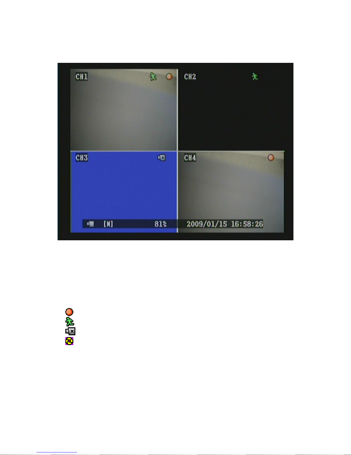
Icon Description
CH2 : Black screen indicates display and record function switched OFF.
CH3 : Blue screen indicates video-loss.
[M] : Symbol [M] indicates manual recording.
Symbol [S] indicates schedule recording.
When both manual and schedule recording has been enabled, manual
recording will be the first priority to be displayed.
: Currently under recording.
: Motion event detected.
: Video input unable to be detected (video-loss has occurred).
: HDD is overwriting data.
Page 14
13
7.4 Playback Mode
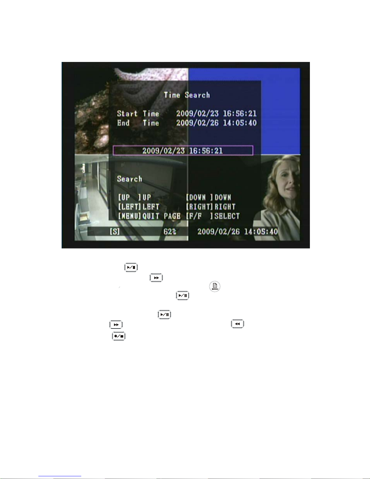
1. Press Play《 》button to enter “Time Search” display.
2. Press Fast Forward《 》button to enter Time Setup mode. After time
setup has been completed, press《 MENU 》button to return to Time
Search display and press Play《 》button again to playback the selected
time.
3. During playback press《 》button to pause and press again to playback.
4. Press《 》button to fast forward playback and《 》button to rewind.
5. Press《 》button to stop playback.
Page 15
14
8. SYSTEM SETUP
8.1 Menu Setup
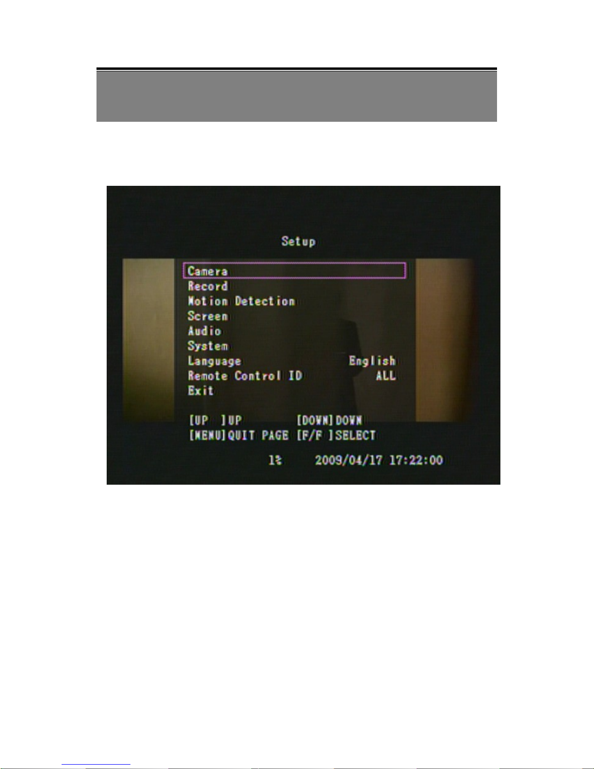
(1) MAIN MENU: Item subject (First menu layer does not have a subject).
(2) Menu Layer Indication: The device consists of four menu layers.
■
:First Menu Layer (Main Menu)
■■
:Second Menu Layer
■■■
:Third Menu Layer
■■■■
:Fourth Menu Layer
(1)
(3)
(4)
(2)
Page 16

15
(3) Menu Operation and Setup
Press《▲》 or《▼》button to move the cursor.
Press《 》or《X》button enter the sub menu.
Press《 MENU 》button.
Under second or third menu layer, the system will return to the previous
menu layer (second layer to first layer or third layer to second layer) and
auto updates the modified data.
Under main menu (first menu layer), the system will enter live mode.
Press《►》button, to increase or decrease the setting values that has been
highlighted.
(4) Menu Layer Operation Guide.
Item Description
[ CAMERA ] Use this option for video to adjust Channel, Display & Record,
Brightness, Contrast, Hue and Saturation.
[ RECORD ] Under this selection user may setup the following function: Record
Frame, Record Quality, Event Record Duration, and Record Schedule.
[ MOTION DETECTION ] Under this selection user may setup the following
function: Channel, Sensitivity and Motion Area.
[ SCREEN ] Under this selection user may setup the following function: Border,
Video Adjustment and Auto Switching.
[ AUDIO ] Under this selection user may setup the following function: Record &
Mute, Input Volume, and Output Volume.
[ SYSTEM ] Under this menu user may the following function: Hard Disk Setup,
Password Setup, Time Set, Event List, Loss Alarm, Motion Alarm, Alarm Duration,
and F/W Upgrade.
[ LANGUAGE ] You can choose either English or Chinese OSD display. You can
change it by pushing “X” to select between English/ Chinese.
[ REMOTE CONTROL ID ] Setup DVR Remote Control ID.
[ EXIT ] After changes have been made on the DVR menu, you need to confirm the
changes under EXIT menu.
Page 17
16
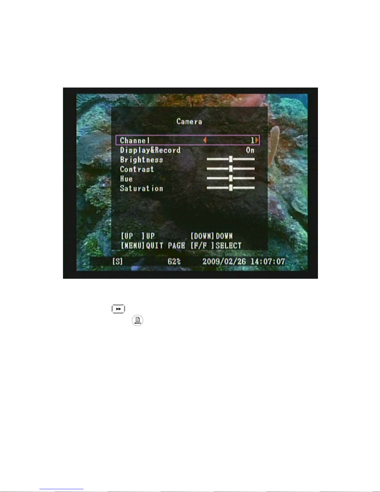
8.2 Camera Setup
1. Press《▲》and《▼》button to move up and down the menu item.
2. Press《 》or《X》button to make changes.
3. Press《MENU 》button to exit “Camera Setup” menu.
4. [Camera Setup] is situated on the second menu layer. Under this selection
user may setup the following function: Channel, Display & Record,
Brightness, Contrast, Hue and Saturation.
■■
Page 18
17
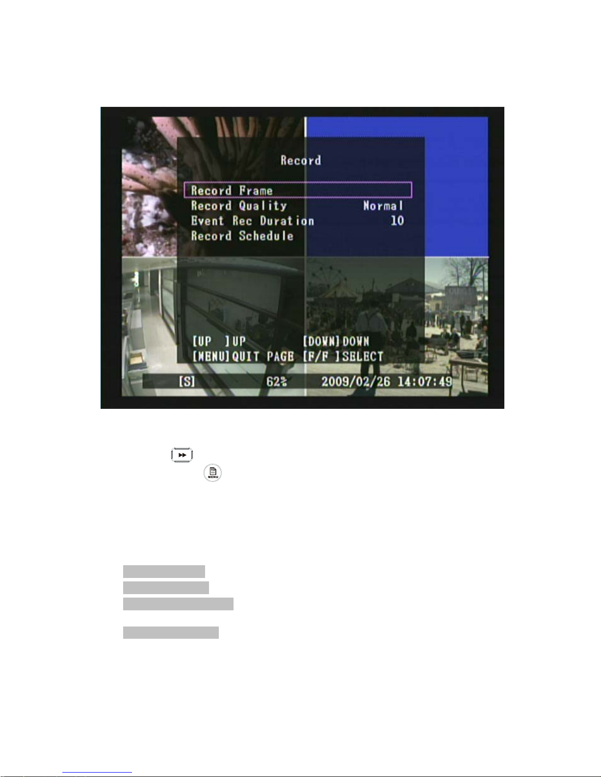
8.3 Record Setup
1. Press《▲》and《▼》button to move up and down the menu item.
2. Press《 》or《X》button to make changes or to enter a next menu layer.
3. Press《MENU 》button to exit “Record Setup” menu.
4. [Record Setup] is situated on the second menu layer. Under this selection user
may setup the following function: Record Frame, Record Quality, Event
Record Duration, and Record Schedule.
Item Description
[ Record Frame ] Record frames per second.
[ Record Quality ] Select Video Quality: [High/ Normal/ Low] .
[ Event Rec Duration ] When schedule recording is under motion detection mode,
system starts recording when motion event has been triggered.
[ Record Schedule ] Three Types of Schedule Record – No Record/ Time Record/
Motion Detection
■■
Page 19
18
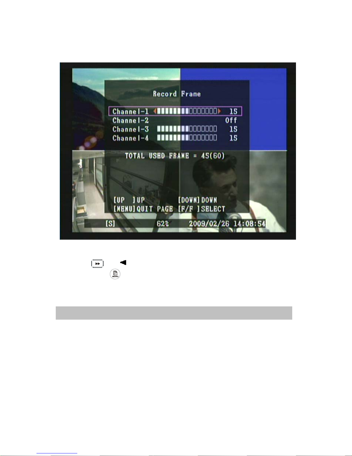
8.3.1 Record Frame
1. Press《▲》and《▼》button to move up and down the menu item.
2. Press《 》,《 》or《X》button to make changes.
3. Press《MENU 》button to exit “Record Schedule Setup” selection.
Maximum frames for all 4 channels are 60 (NTSC)/ 50 (PAL) frames.
■■■
Note: Recording frames for each channel is (0 frames) or 3 ~ 30 frames.
Page 20
19
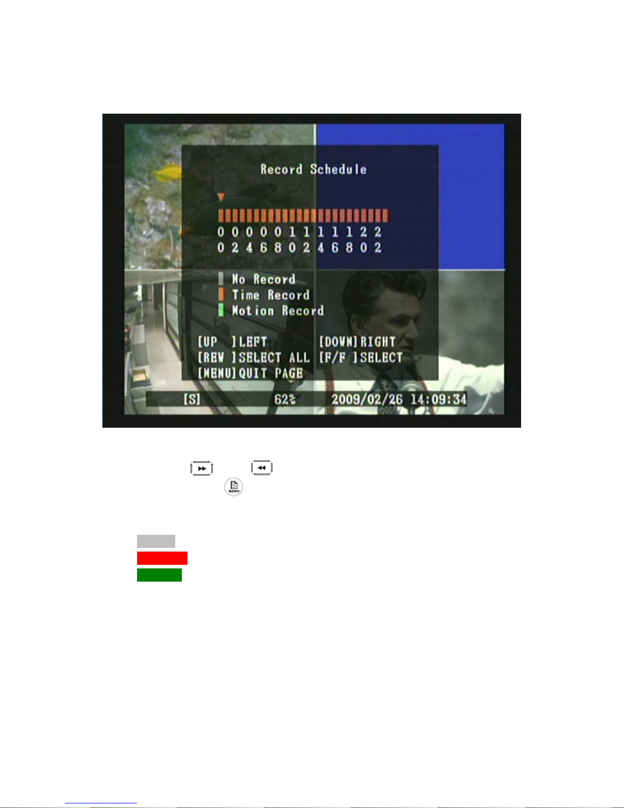
8.3.2 Record Schedule
1. Press《▲》and《▼》button to move up and down the menu item.
2. Press《 》or《 》button to make changes.
3. Press《MENU 》button to exit “Record Schedule Setup” selection.
Color Bar Description
[ Grey ] Indicates no record will be made for this time period.
[ Orange ] Indicates recording is made for this time period.
[ Green ] Indicates built-in motion sensor recording (For more information, please
refer to 8.4“MOTION DETECTION”).
■■■
Page 21
20
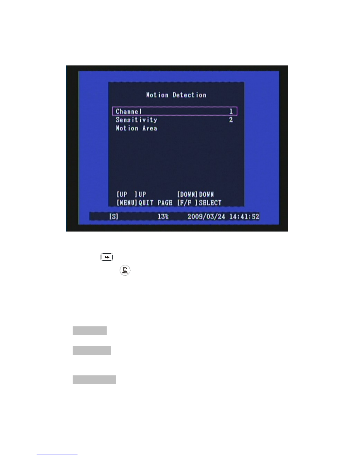
8.4 Motion Detection Setup
1. Press《▲》and《▼》button to move up and down the menu item.
2. Press《 》or《X》button to make changes or to enter a next menu layer.
3. Press《MENU 》button to exit “Motion Detection” menu.
4. [Motion Detection Setup] is situated on the second menu layer. Under this
selection user may setup the following function: Channel, Sensitivity and
Motion Area.
Item Description
[ Channel ] Select the channel (1,2,3,4) for recording mode by internal motion
sensor.
[ Sensitivity ] It adjusts the sensitivity of the built-in motion sensor on the DVR
system while recording. The lower the number, the higher the sensitivity rate
(maximum sensitivity level is 4).
[ Motion Area ] Use this option to select the range of motion detection area. Use the
keypad button, remote control button to assign the area.
■■
Page 22
21
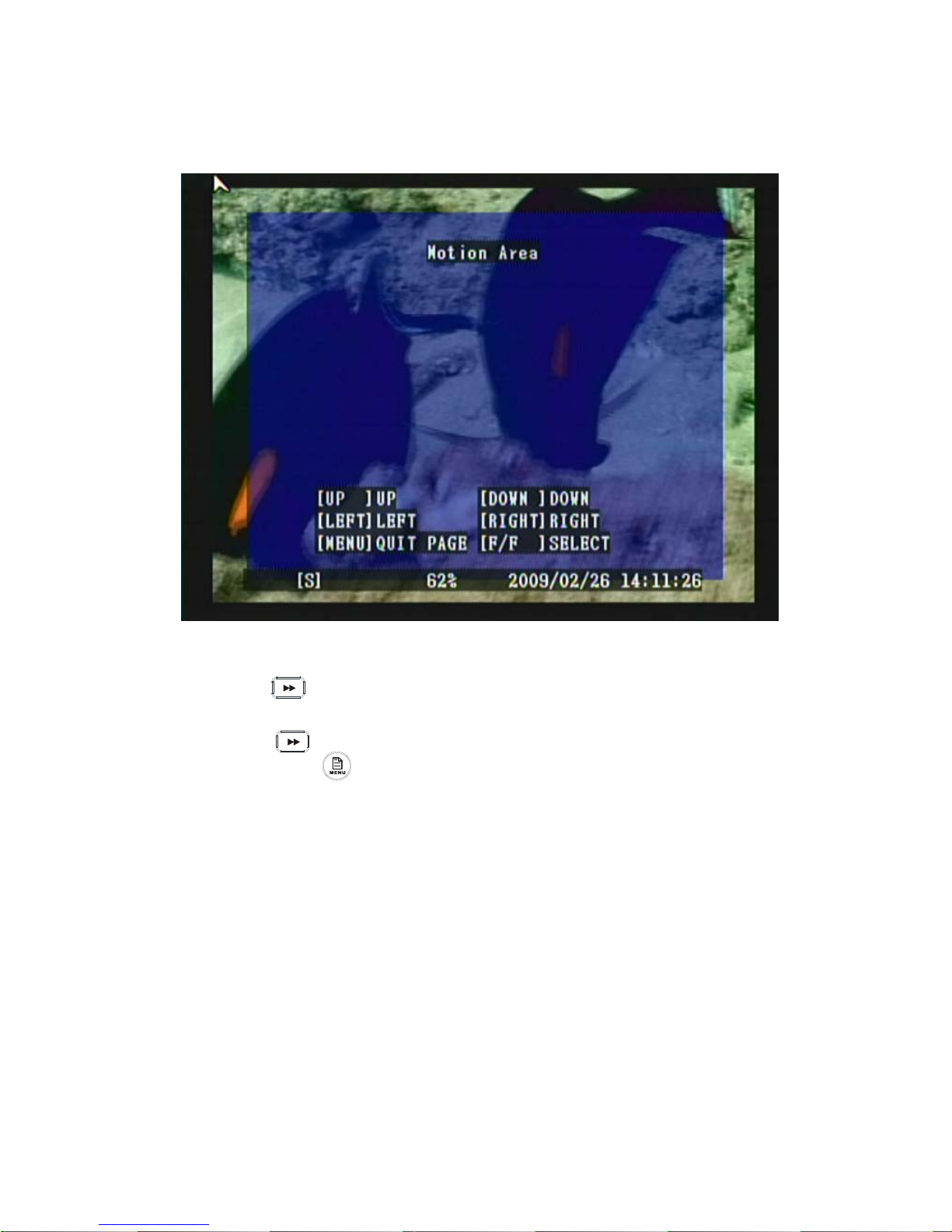
8.4.1 Motion Area
1. Press《▲》and《▼》button to move up and down the menu item.
2. Press《 》button to setup the starting point of the motion area.
3. Press《▲》and《▼》to select the range of motion detection area.
4. Press《 》button to setup the ending point of the motion area.
5. Press《MENU 》button to exit “Motion Area” selection.
As shown above, color blue indicates motion area.
■■■
Page 23
22
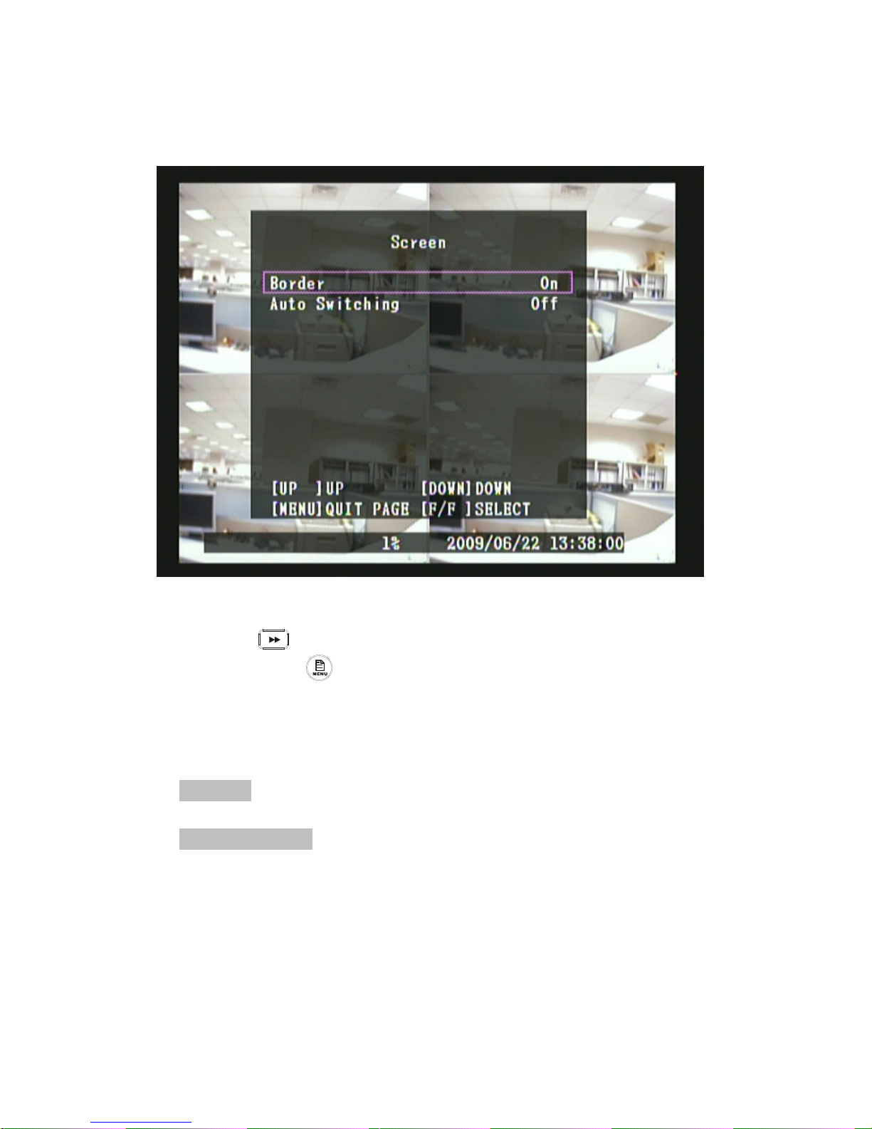
8.5 Screen Setup
1. Press《▲》and《▼》button to move up and down the menu item.
2. Press《 》or《X》button to make changes or to enter a next menu layer.
3. Press《MENU 》button to exit “Screen Setup” menu.
4. [Screen Setup] is situated on the second menu layer. Under this selection
user may setup the following function: Border and Auto Switching.
Item Description
[ Border ] You can make the white border line around each channel to appear or
disappear (On/ Off).
[ Auto Switching ] This is for auto screen switch rotation.
■■
Page 24
23
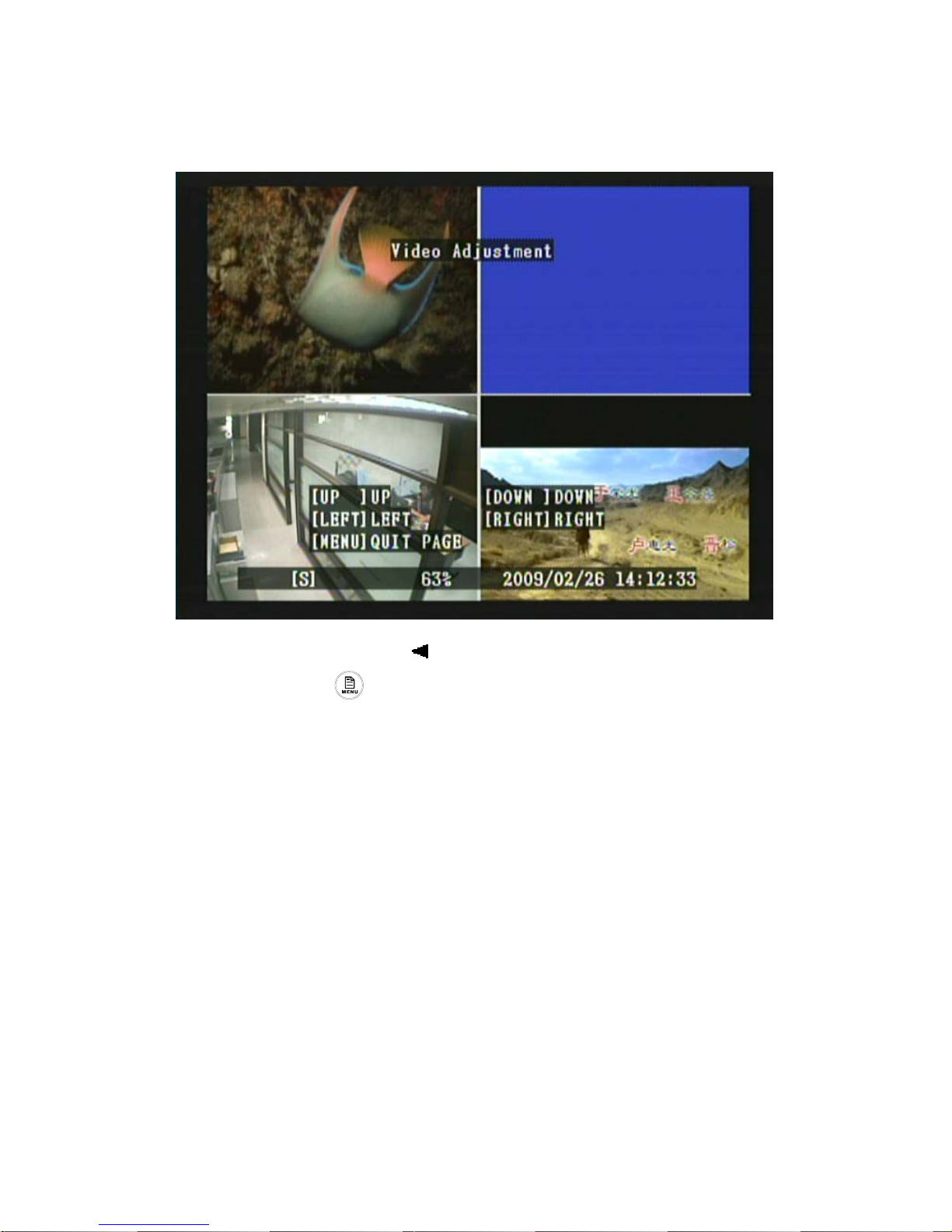
8.5.1 Video Adjustment
1. Press《▲》, 《▼》, 《 》or《X》button to adjust the screen.
2. Press《MENU 》button to exit “Video Adjustment” selection.
■■■
Page 25
24
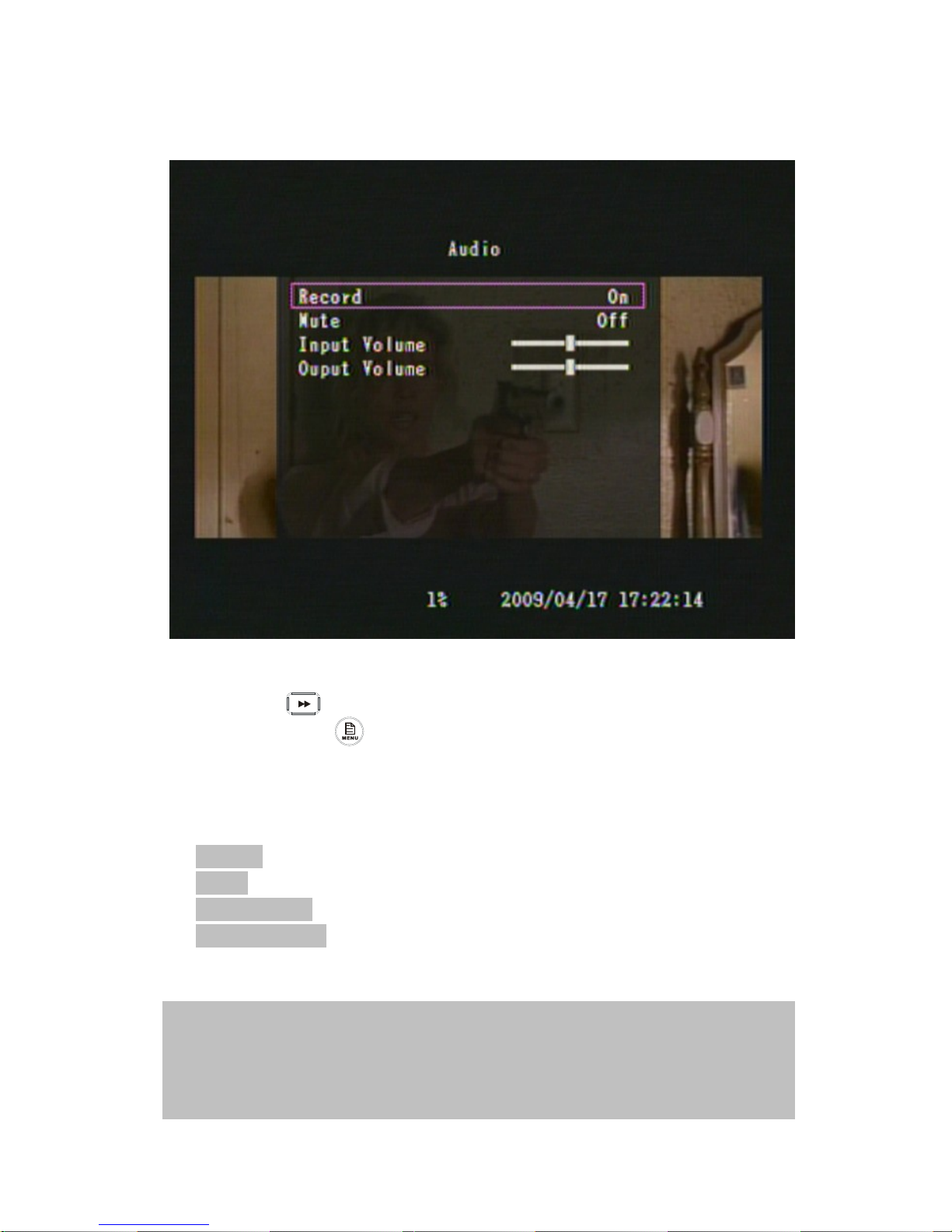
8.6 Audio Setup
1. Press《▲》and《▼》button to move up and down the menu item.
2. Press《 》or《X》button to make changes
3. Press《MENU 》button to exit “Audio Setup” menu.
4. [Audio] is situated on the second menu layer. Under this menu user may setup
the following function: Record, Mute, Input Volume and Output Volume.
Item Description
[Record] Setup audio recording for Channel 1 On/ Off.
[Mute] Enable/ Disable mute function.
[Input Volume] Setup volume input for Channel 1 High/ Low.
[Output Volume] Setup volume output for Channel 1 High/ Low. When the output
volume is at its minimum level, mute function is auto started.
■■
NOTE1 : Audio recording is made available fixed only in Channel 1.
NOTE2 : Move the sound input and output volume cursor more to the right, the greater the volume.
NOTE3 : Input volume is at its maximum volume when under Live mode.
NOTE4 : Output volume is at its minimum volume when under Playback Control mode.
Page 26
25
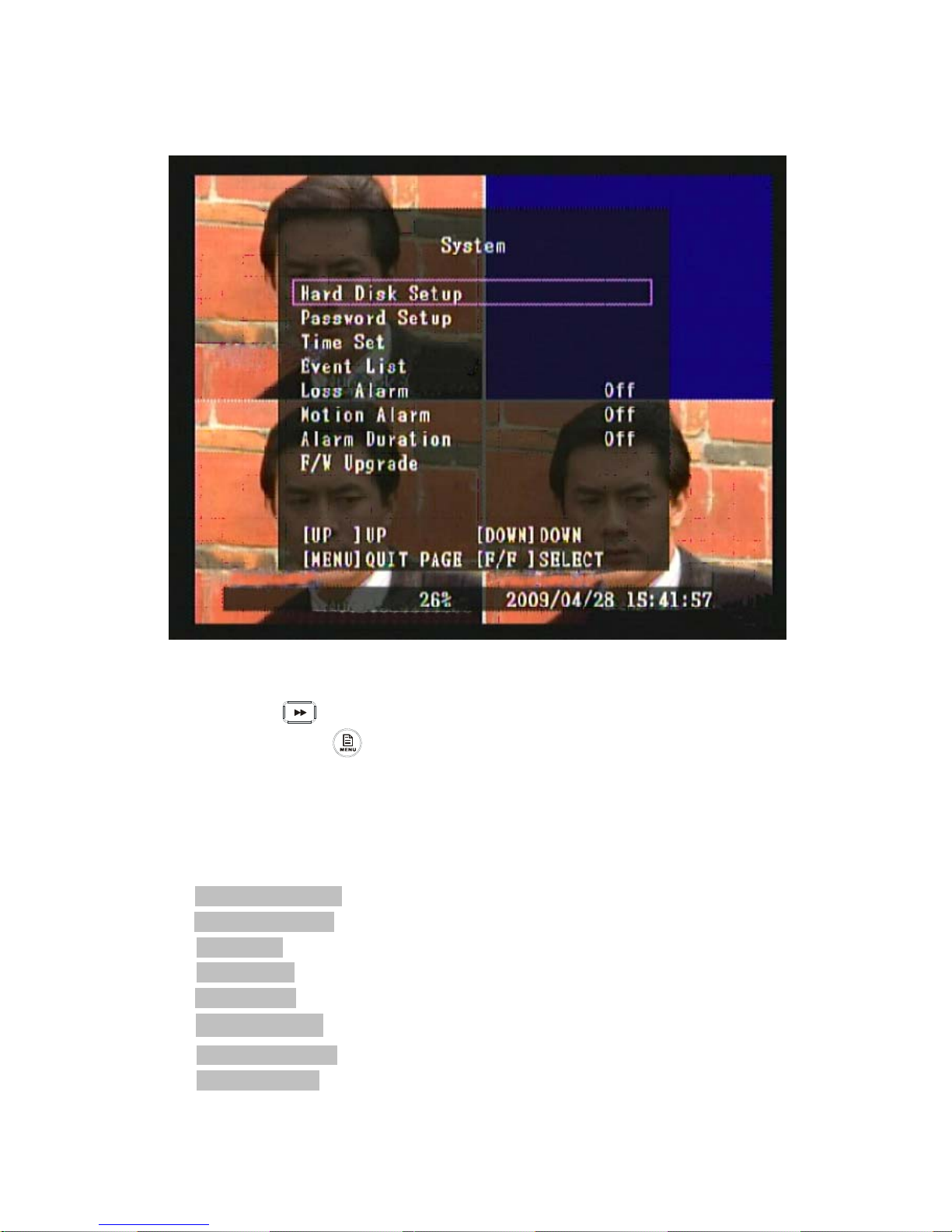
8.7 System Setup
1. Press《▲》and《▼》button to move up and down the menu item.
2. Press《 》or《X》button to make changes or to enter a next menu layer.
3. Press《MENU 》button to exit “System Setup” menu.
4. [System Setup] is situated on the second menu layer. Under this menu user may
setup the following function: Hard Disk Setup, Password Setup, Time Set,
Event List, Loss Alarm, Motion Alarm, Alarm Duration and F/W Upgrade.
Item Description
[ Hard Disk Setup ] Overwrite and format HDD.
[ Password Setup ] Password must be 6 digits. Default Password: 111111.
[ Time Set ] You can adjust the current time, date, and year at any time by region.
[ Event List ] EVENT LIST function enables playback by event.
[ Loss Alarm ] Decides whether to trigger buzzer or not when video loss occurs.
[ Motion Alarm ] Decides whether to trigger buzzer or not when motion is detected.
[ Alarm Duration ] Decides the duration time when buzzer is triggered.
[ F/W Upgrade ] Upgrade DVR system through USB host (USB memory stick).
■■
Page 27
26
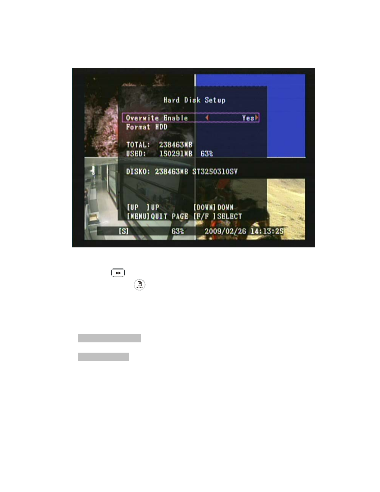
8.7.1 Hard Disk
1. Press《▲》and《▼》button to move up and down the menu item.
2. Press《 》and《X》button to make changes or to enter a next menu layer.
3. Press《MENU 》button to exit “Hard Disk” selection.
4. [Hard Drive Setup] is situated on the third menu layer. Under this menu
layer user may setup to overwrite or format the hard disk.
Item Description
[ Overwrite Enable ] Setup whether or not to overwrite recording when the hard
disk is full.
[ Format HDD ] If you format the hard drive, all the video data stored on the
hard disk drive will be deleted. Remind that the system has no restore option once
the hard drive is formatted.
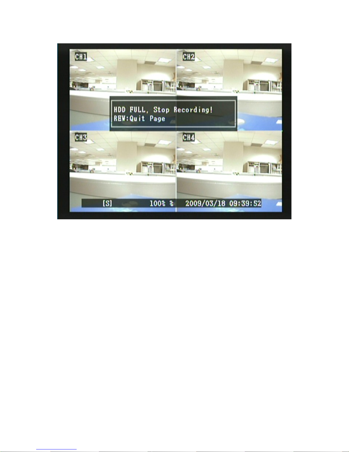
When the hard disk is full and overwrite function is set to No, the following
display appears:
■■■
Page 28
27
Page 29
28
8.7.1.1 Format HDD
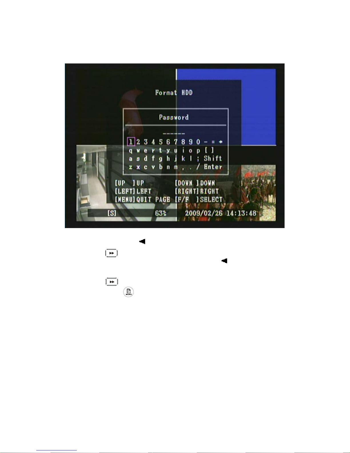
1. Press《▲》, 《▼》, 《 》 or《X》button to move to the desired password number.
2. Press《 》button enter password(must be 6 digits).
3. After entering 6 digits password, use《▲》/《▼》/《 》/《X》button to move
the cursor to “Enter”.
4. Press《 》button to confirm password.
5. Press《MENU 》button to exit “Format HDD” selection.
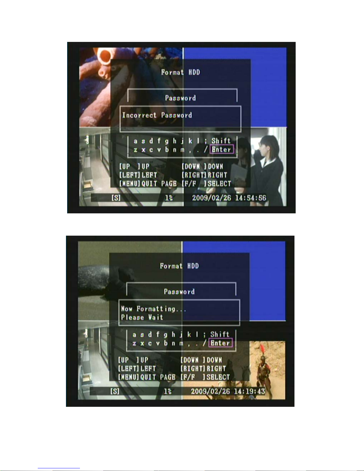
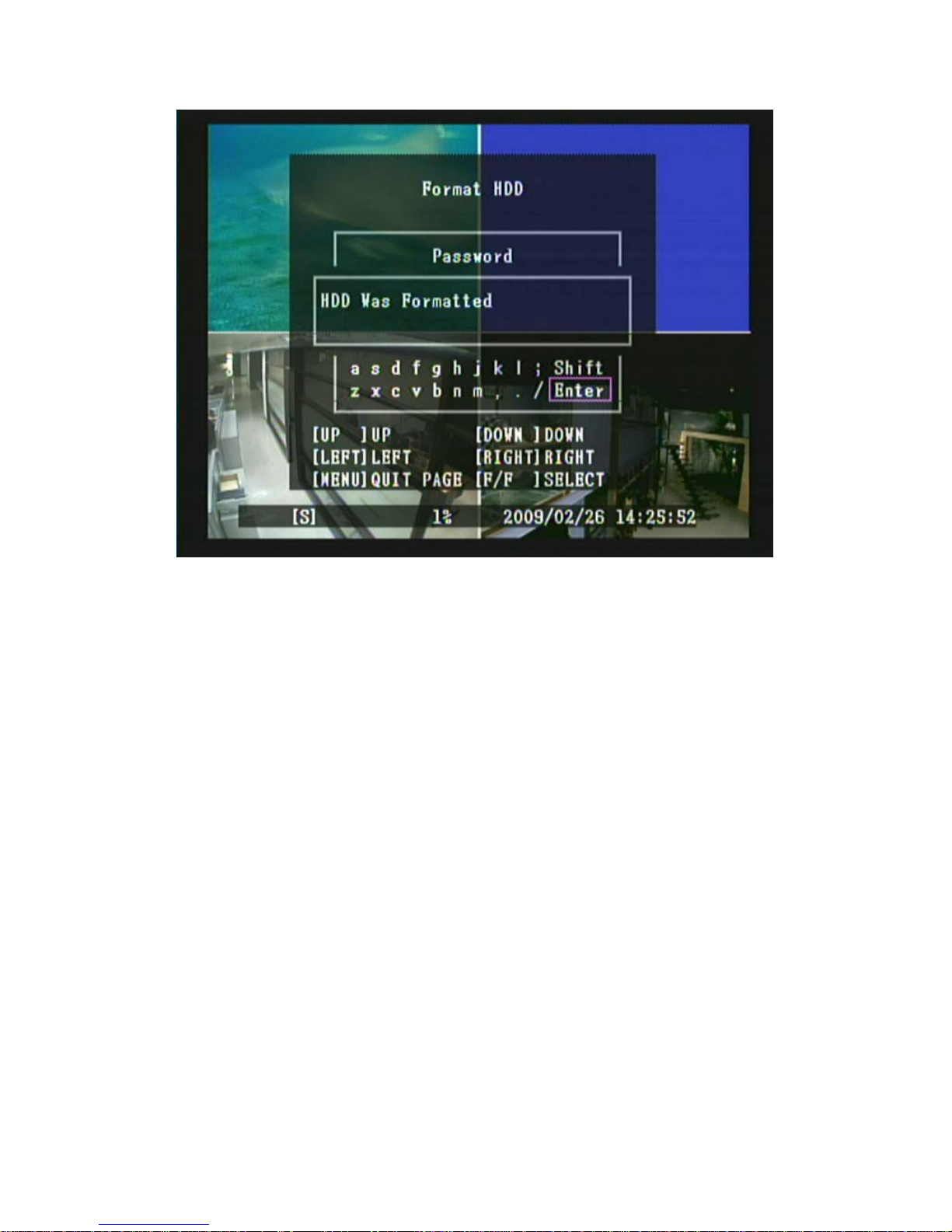
When password entered is incorrect, the screen will display “Incorrect Password” (Fig 1),
and when password entered is correct , the screen will display the message “HDD Was
Formatted” (Fig 2 & Fig 3) , indicates hard disk format is successful and returns to “HARD
DRIVE SETUP” selection.
Default Password: 111111
■■■■
Page 30
29
Fig 1
Fig 2
Page 31
30
Fig 3
Page 32
31
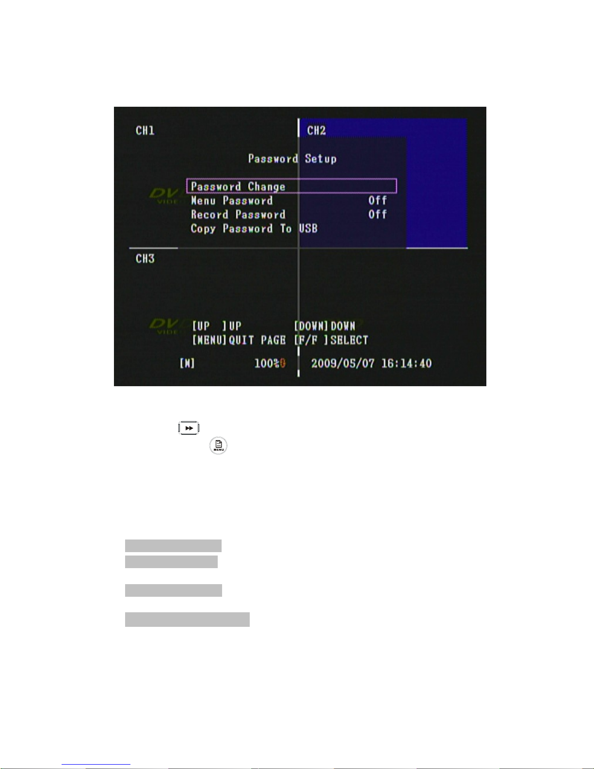
8.7.2 Password Setup
1. Press《▲》and《▼》button to move up and down the menu item.
2. Press《 》or《X》button to make changes or to enter a next menu layer.
3. Press《MENU 》button to exit “Password” selection.
4. [Password Setup] is situated on the third menu layer. Under this selection
user may setup the following function: Password Change, Menu Password
and Record Password.
Item Description
[ Password Change ] Password change settings, Default Password: 111111.
[ Menu Password ] Setup menu password, password is required every time you
enter the menu.
[ Record Password ] Setup record password, password is required every time you
stop manual recording.
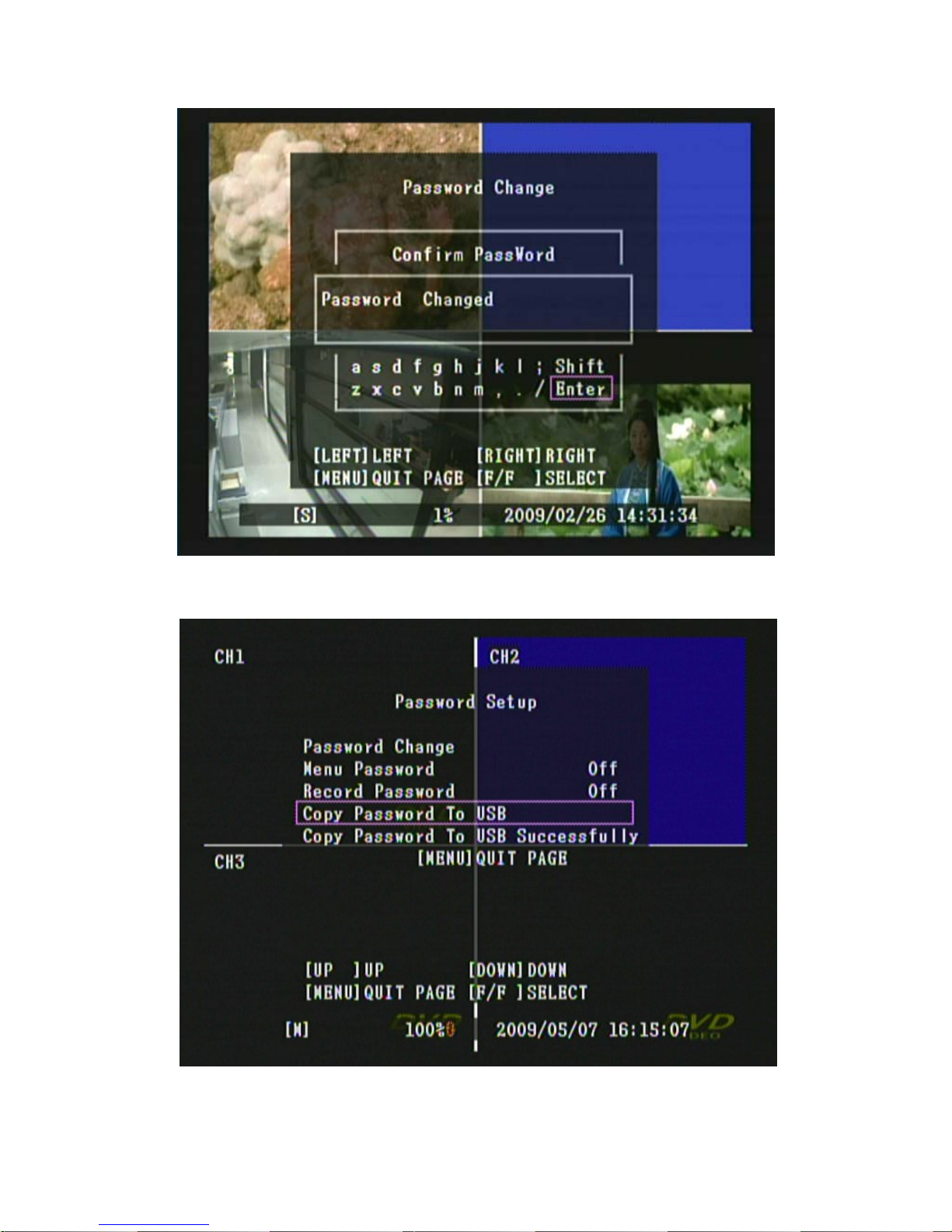
[ Copy Password To USB ] Setup copy password to USB, password is unnecessary
if menu password item function has been set to “On”.
When copy password to USB function has been applied, Fig. 7 is shown.
■■■
Page 33
32
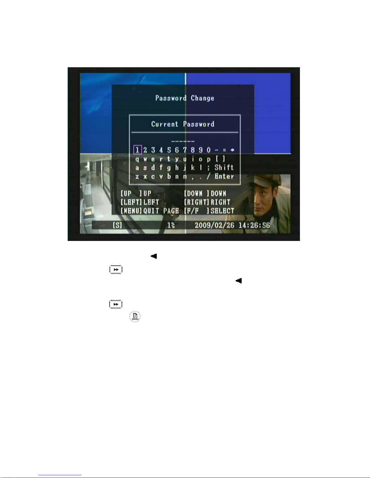
8.7.2.1 Password Change
1. Press《▲》, 《▼》, 《 》or《X》button to move to the desired password number.
2. Press《 》button and enter password(must be 6 digits).
3. After entering 6 digits password, use《▲》/《▼》/《 》/《X》button to move
the cursor to “Enter”.
4. Press《 》button to confirm password.
5. Press《MENU 》button to exit “Password Change” selection.
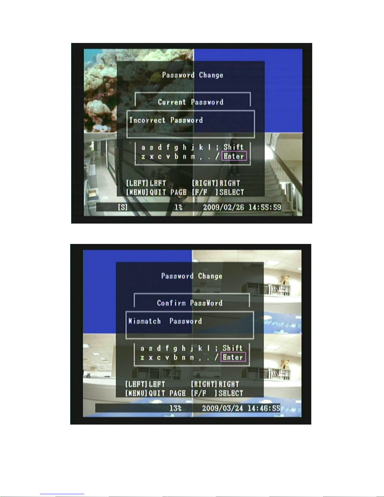
Password change requires entering a total of three groups of password. That is
“Current Password”, “New Password” and “Confirm Password”. When password
entered is incorrect or the password format does not match (Less than 6 digits, Fig 1 is
shown), system returns to password change selection menu. When “Current Password”
entered is correct, but “New Password” and “Confirm Password” entered does not
match (Fig 2 is shown), system returns to password change selection menu. When
password change is successful (Fig 3 is shown), system returns to password change
selection menu.
Default Password : 111111
■■■■
Page 34
33
Fig 4
Fig 5
Page 35
34
Fig 6
Fig 7
Page 36
35
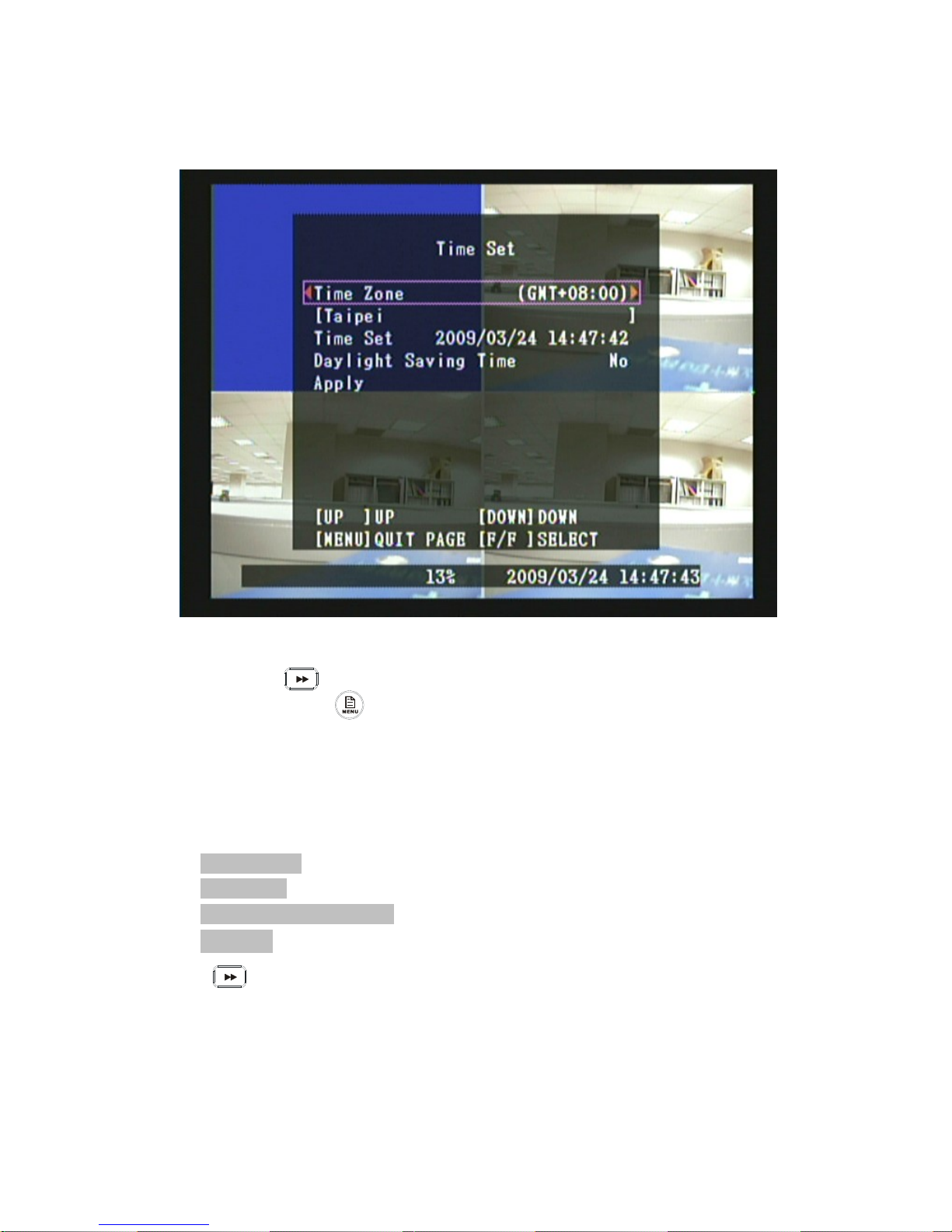
8.7.3 Time Set
1. Press《▲》and《▼》button to move up and down the menu item.
2. Press《 》or《X》button to make changes or to enter change mode.
3. Press《MENU 》button to exit “Time Set” selection.
4. [Time Set] is situated on the third menu layer. Under this selection user may
setup the following function: Time Zone, Time Set, Daylight Saving Time and
Apply.
Item Description
[ Time Zone ] Setup Time Zone
[ Time Set ] Setup Time
[ Day Light Saving Time ] Day Light Saving Time Setup.
[ Apply ] Once you’ve completed time setup, press “Apply” button. Then press
“ ” button to apply the new time set.
■■■
Page 37
36
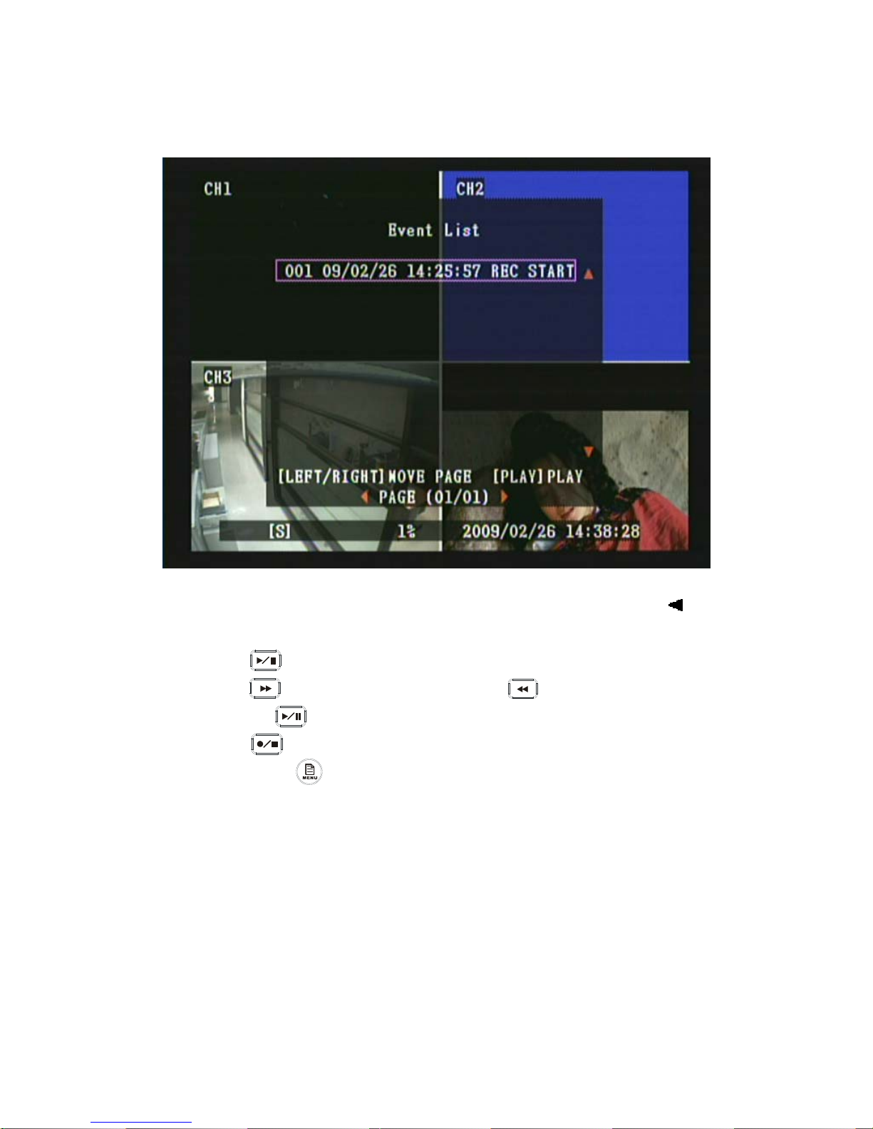
8.7.4 Event List
1. Press《▲》and《▼》button to move to the desired event item or use《 》
and《X》button to move to the previous or next event list page.
2. Press《 》button to playback event.
3. Press《 》button to Fast Forward, press《 》button to Fast Rewind
and press《 》button to Pause/ Stop playback.
4. Press《 》button to stop playback and return to “Event List” selection.
5. Press《MENU 》button to exit “Event List” selection.
■■■
Page 38
37
8.7.5 Software Update
Fig 8
Fig 9
■■■
Page 39
38
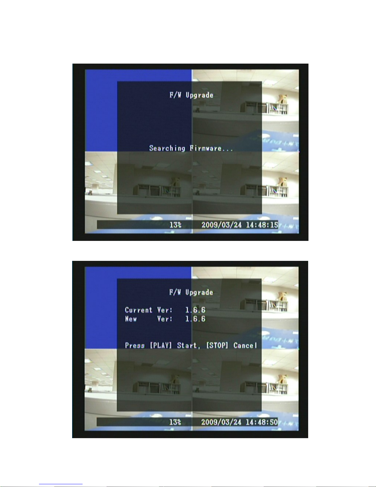
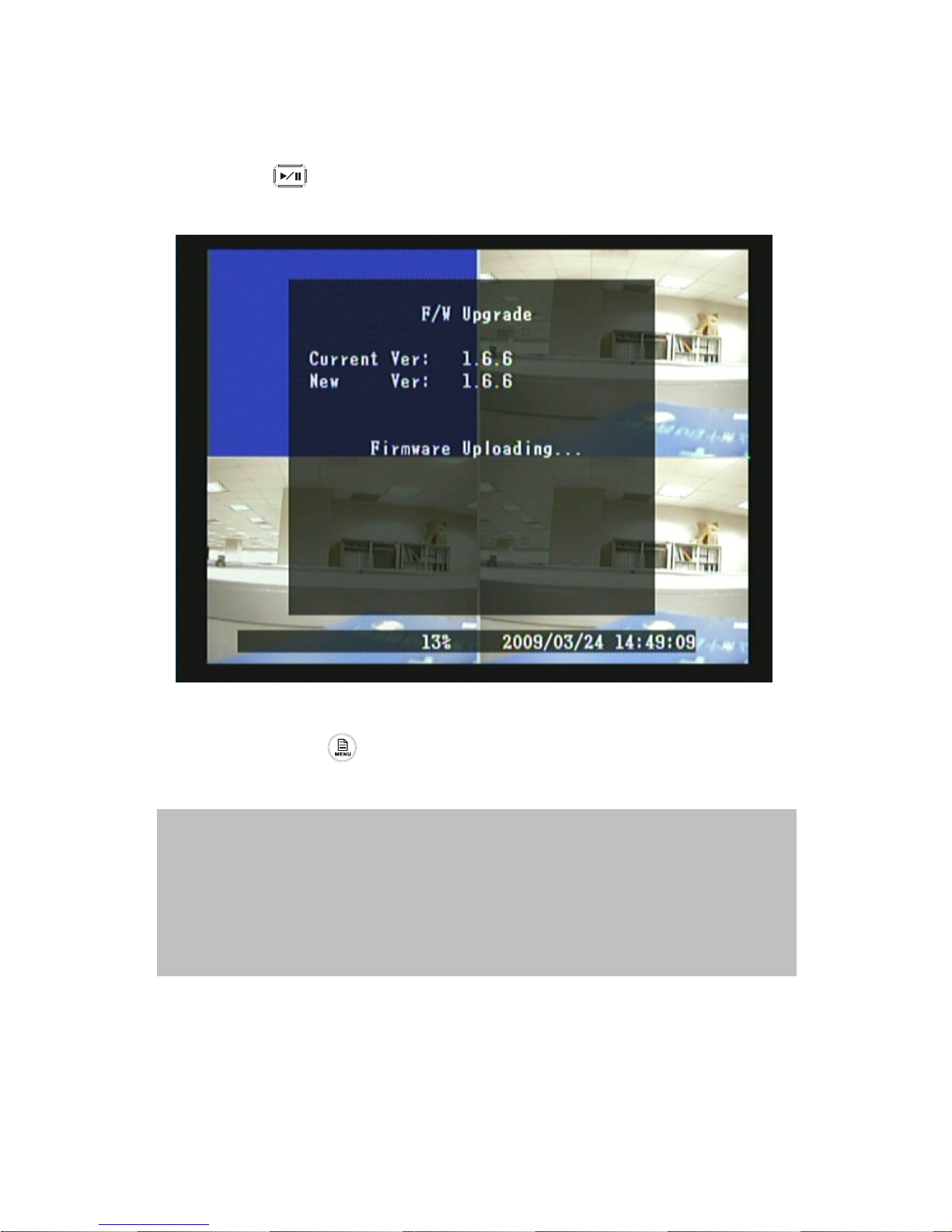
1. When entering software update selection and the USB storage device has firmware
image files stored, Fig 6 is shown and followed by Fig 7.
2. Press《 》button to update software.
3. During update process, Fig 8 is shown.
Fig 10
4. Press《MENU 》button to exit “Software Update” selection.
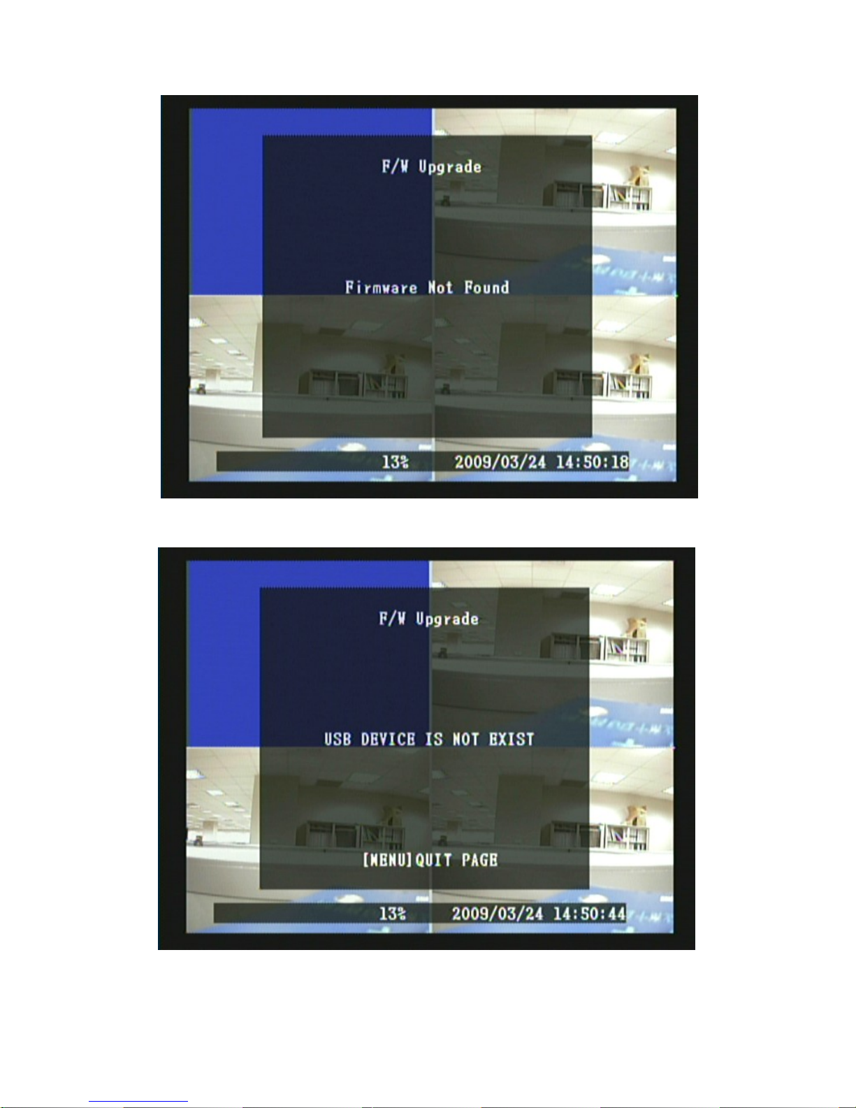
5. When the USB storage device has no firmware images stored, Fig 9 is shown.
NOTE 1: Please do not remove the USB storage device while the firmware has started
updating, otherwise system damage may occur.
NOTE 2: No USB storage device has been connected when entered Firmware Update selection,
Fig 10 is shown.
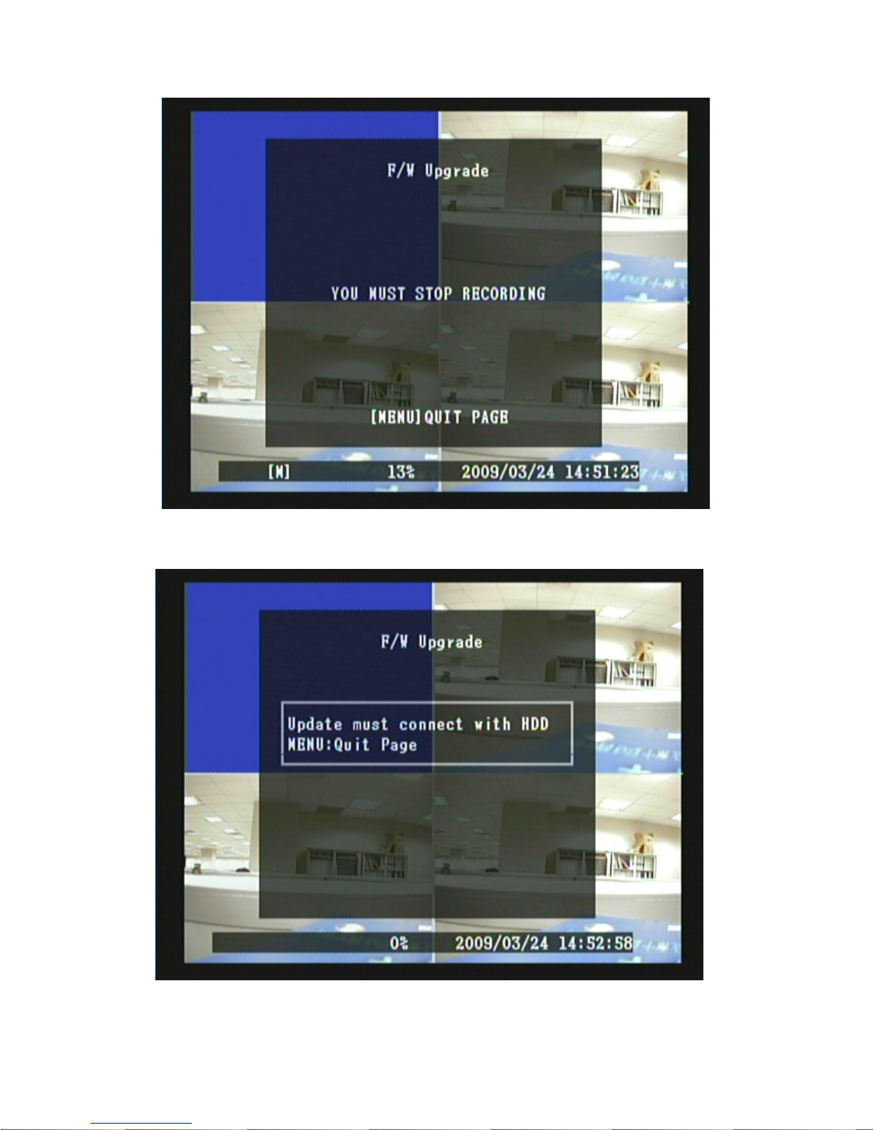
NOTE 3: Please stop recording before proceeding firmware update, otherwise Fig 11 is shown.
NOTE 4: Please Connect the HDD before proceeding firmware update, otherwise Fig 12 is
shown.
Page 40
39
Fig 11
Fig 12
Page 41
40
Fig 13
Fig 14
Page 42
41
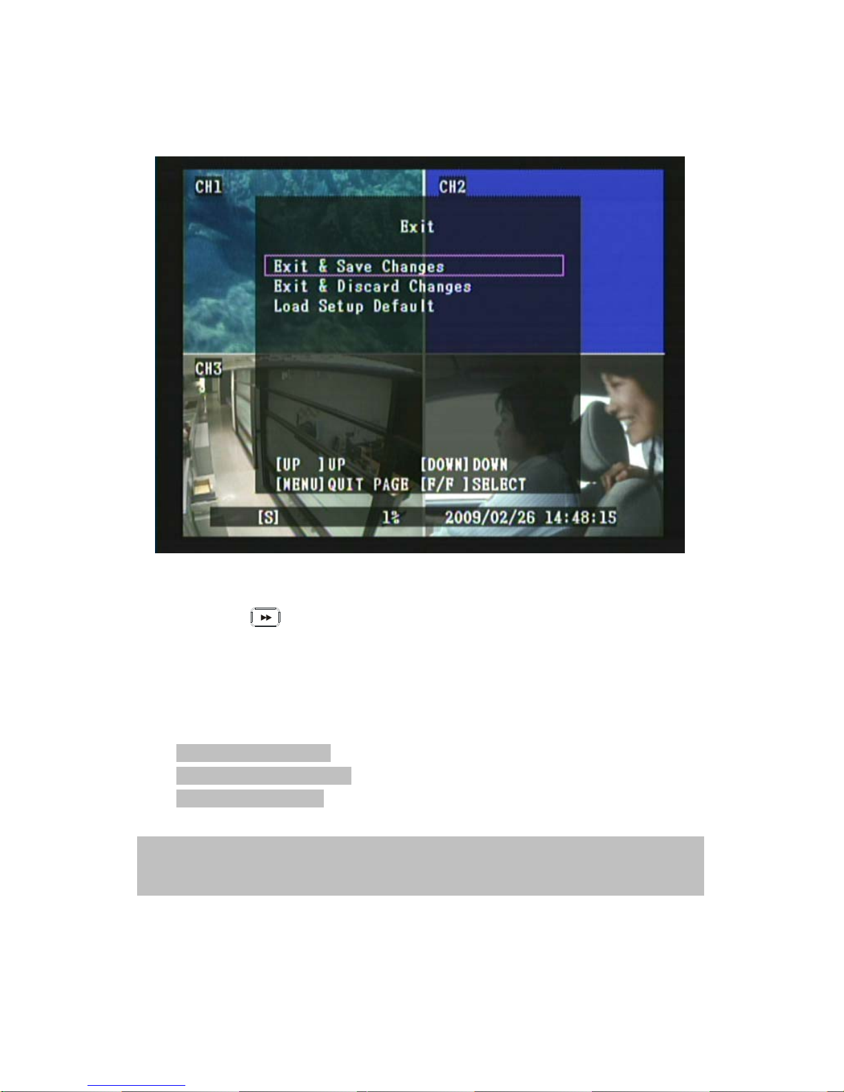
8.8 Exit
1. Press《▲》and《▼》button to move up and down the menu item.
2. Press《 》button to confirm.
3. [Exit] is situated on the second menu layer. Under this selection user may
setup the following function: Exit & Save Changes, Exit & Discard Changes
and Load Setup Default.
Item Description
[ Exit & Save Changes] Save new parameter and return to LIVE mode.
[ Exit & Discard Changes] No change and return to LIVE mode.
[ Load Setup Default ] Load default setting.
■■
NOTE : Factory Default Setup – Enter MENU and select item “EXIT”, proceed “Load Setup
De fa ult” to re turn to factory defa ul t ( Default Password : 111111 ). System returns to fact or y
de fa ult (111111) after returned to LIVE disp la y.
Page 43
42
8.9 Backup via USB Memory Stick
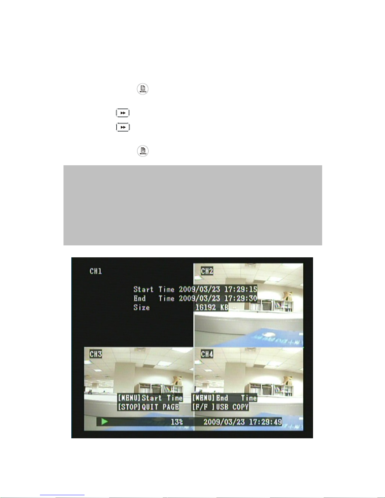
1. In order to save the video data with USB memory stick, you should first stop
record and enter playback mode, as shown below (Fig 13).
2. 2. Press《MENU 》button to setup the start and end time period of recorded
video data that you want to save on the USB memory stick.
3. 3. Press《 》button to enter backup mode, as shown below (Fig 14).
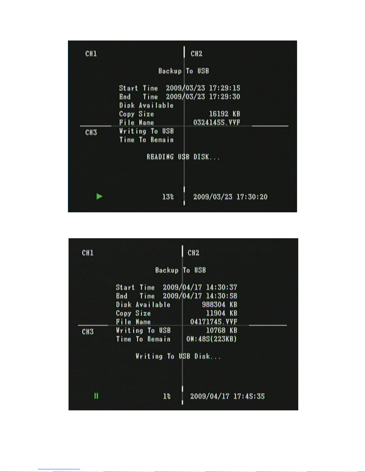
4. 4. Press《 》button again to start backup, as shown below (Fig 15).
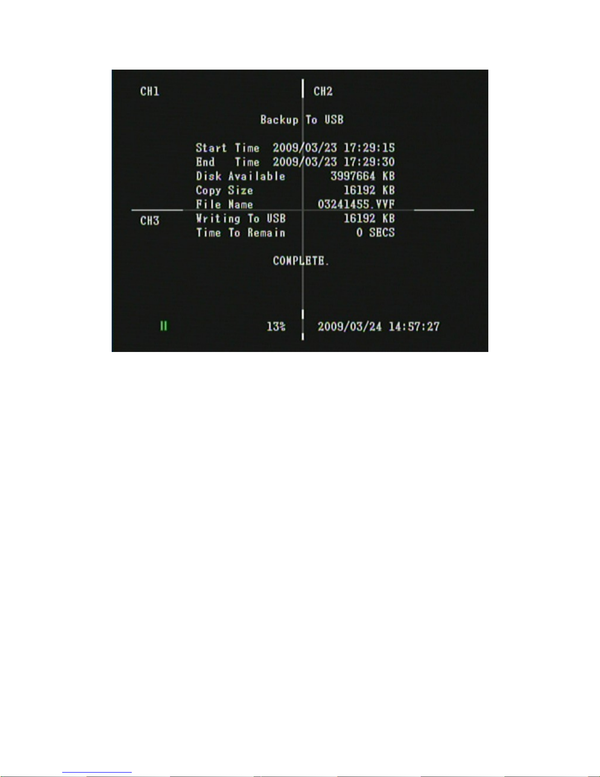
5. When backup has been completed a window appears as shown below (Fig 16).
6. 6. Press《MENU 》button to exit “USB Backup” selection.
Fig 15
NOTE 1: When applying USB backup function for the first time, please proceed using your PC
to format (FAT32/ FAT16) the USB storage device.
NOTE 2: Maximum data size is 1GB per every image data backup (data exceeding 1GB, a
message “Data Size Is Too Big To Copy” appears.
NOTE 3: During the process of USB backup, it will also copy the remote PC client software to
the USB flash drive.
NOTE 4: Please do not unplug the USB in the process of backup!
NOTE 5: The system will restart in a minute after file copy abnormality occurs. When this
happens, it is suggested to replace the USB flash drive, and then restart back-up.
Page 44
43
Fig16
Fig 17
Page 45
44
Fig 18
Page 46
45
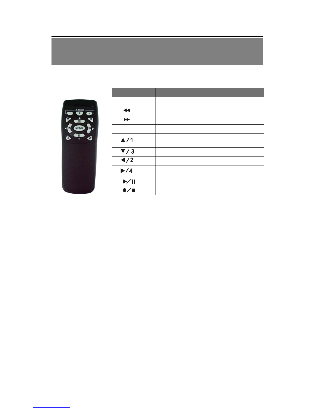
9. REMOTE CONTROL (option)
Remote Control ID
Button Name Description
○
1 CHECK ID
Remote Control ID
○
2
Rewind
○
3
Fast Forward/ Enter Selection
○
4 MENU
Enter / Exit Menu
○
5
Up direction button / CH 1 screen display
○
6
Down direction button / CH 3 screen display
○
7
Left direction button / CH 2 screen display
○
8
Right direction button/ Enter Selection/ CH 4 screen
display
○
9
Play/ Pause
○
6
○
10
Record/ Stop
Enter MENU and select item Remote Control ID to setup remote controller ID.
(1) Enter MENU find item Remote Control ID and setup a set of number for
CHECK ID (Remote control ID consists of 10 sets of the numbers: ALL, 11, 12,
13, 21, 22, 23, 31, 32, 33).
(2) After Remote Control ID setup, you must return to LIVE monitoring mode.
Because the setup is only effective if you return to LIVE mode after the setup.
(3) After returning to LIVE monitoring mode, press remote control CHECK ID
(ALL, 11, 12, 21, 22, 23, 31, 32, 33) to confirm synchronization. When the
message “
REMOTE ID IS CORRECT” appears, indicate synchronize function setup
is complete. Now you are able to control the DVR using remote control.
(4) Each time, synchronization allows only one single device to be controlled by a
single remote control.
○
1
○
2
○
3
○
4
○
5
○
6
○
7
○
8
○
9
○
10
Page 47
46
10. HDD Player Software Description
System Requirement
OS (Operating System) Windows XP.
Hardware Requirement
CPU ※ 2.8GHz or higher.
RAM ※ 1GMByte or higher.
1. Installation
Software Installation
1. During installation, you will need a desktop or laptop computer that meets these
minimum requirements: Windows XP.
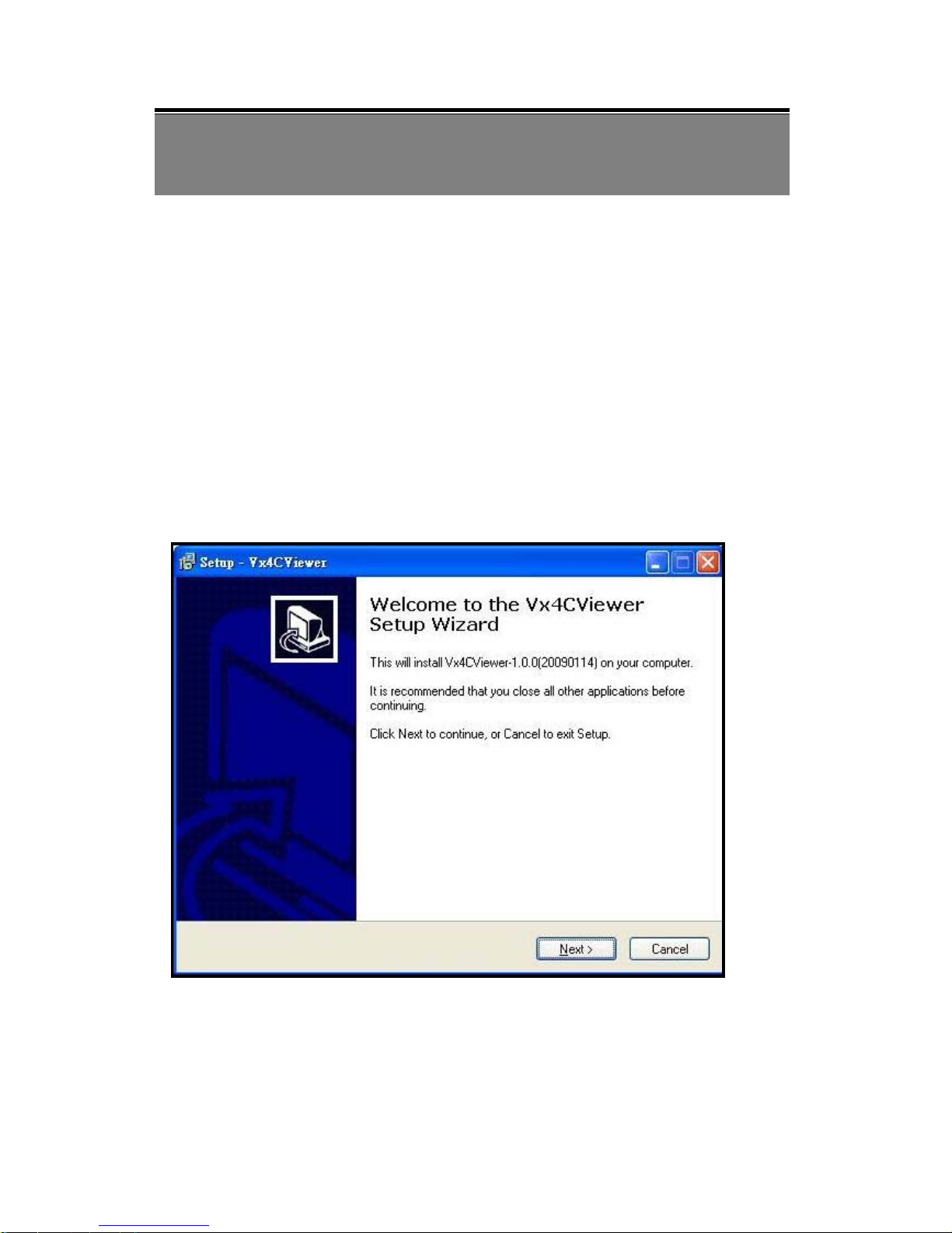
2. Run the program “Vx4CViewer-setup.exe” on the supplied CD by double
clicking the icon shown below:
Remote Software Installation
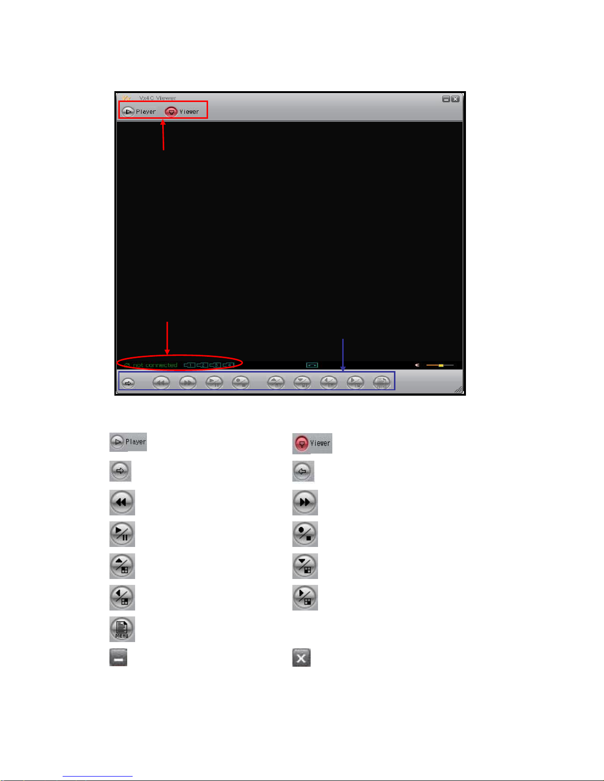
After the software installation is complete; open-upVx4CViewer and then move the
cursor to [Viewer] button. Left mouse click to enter Viewer User Interface, as shown
below:
Page 48
47
User Interface
Viewer Function Button Description
Press this button to enter player
window.
Press this button to enter DVR Viewer
connection window.
Press this button to enter DVR
login window.
Press this button to disconnect from
DVR.
Fast Rewind (similar to DVR front
panel function button).
Fast Forward (similar to DVR front
panel function button).
Play/ Pause (similar to DVR front
panel function button).
Record/ Stop (similar to DVR front
panel function button).
Up Direction/ CH1 (similar to
DVR front panel function button).
Down Direction/ CH3 (similar to DVR
front panel function button).
Left Direction/ CH2 (similar to
DVR front panel function button).
Right Direction/ CH4 (similar to DVR
front panel function button).
Main Menu (similar to DVR front
panel function button).
Press this button to minimize
Viewer window.
Press this button to close Viewer software.
Mouse
Right
Button
Activate Viewer setup menu
Connection Status
Function Button
Viewer/ Player
Page 49
48
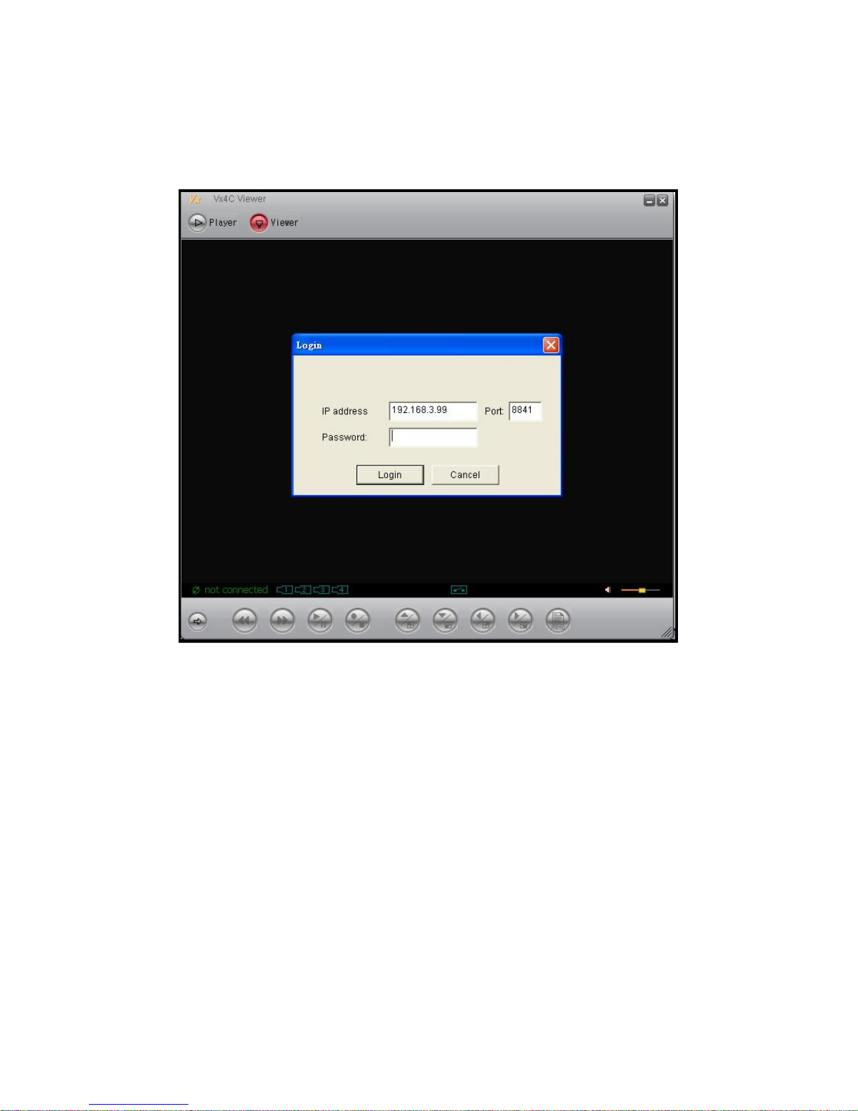
2.1 DVR Connection (Applicable only to Network DVR)
After pressing the connection button, a Login window appears. Please enter DVR IP
address, remote-site Password, and Port to enter DVR connection window.
Page 50
49
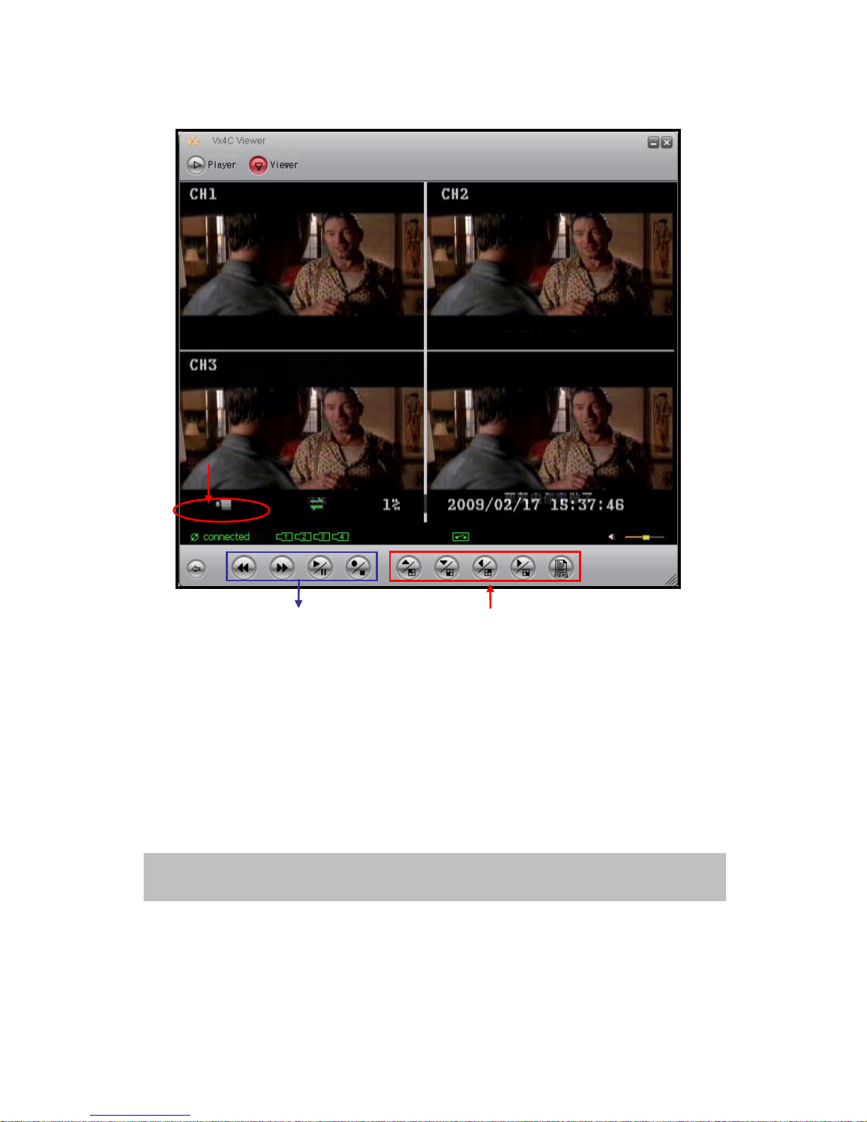
After entering DVR LIVE display, use panel button for operation control.
Connection Status: Display current connection status (figure shown above), system
indicates either connected or disconnected. When the Viewer network disconnects,
Viewer tries to automatically re-connect.
Screen Switching Button: Enables screen switching between Quad-Screen display/
Single-Screen display and activates DVR setup menu.
DVR Player Operation Button: Enables playback control on the DVR-site.
NOTE: DVR screen follows to any changes in the Viewer operation (prior to any screen
operation and MENU setup changes).
Connection Status
Screen Switching Button
DVR Player Operation Button
Page 51
50
2.2 DVR Setup (Applicable only to Network DVR)
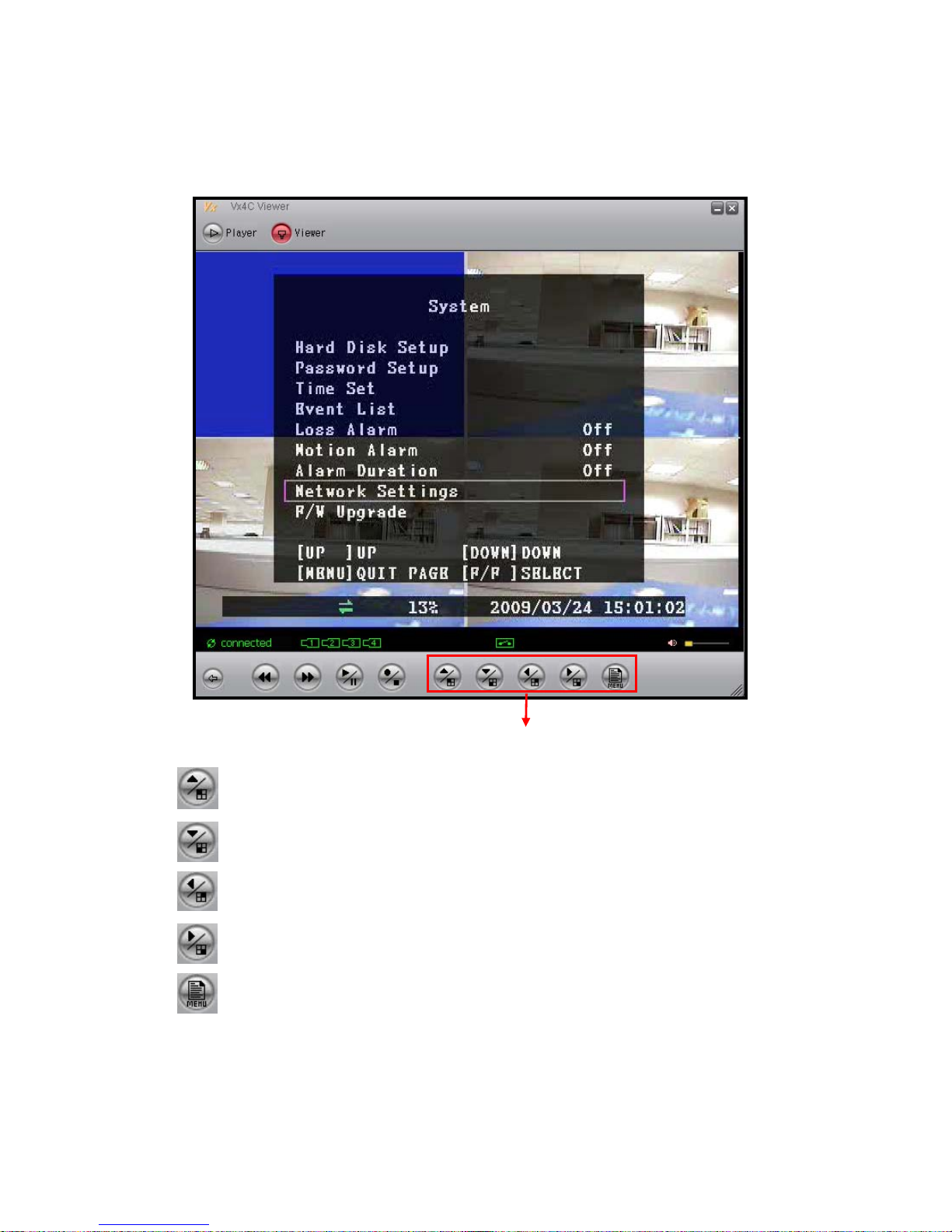
Press [MENU] button to activate DVR setup menu and precede DVR function setup.
CH1 (similar to DVR-site button application)/ UP (similar to menu button application).
CH3 (similar to DVR-site button application)/ DOWN (similar to menu button application).
CH2 (similar to DVR-site button application)/ LEFT (similar to menu button application).
CH4 (similar to DVR-site button application)/ RIGHT (similar to menu button application).
MENU (similar to DVR-site button application). Press to activate DVR setup menu and to
precede DVR function setup.
Function Button
Page 52
51
2.3. Viewer Setup (Applicable only to Network DVR)
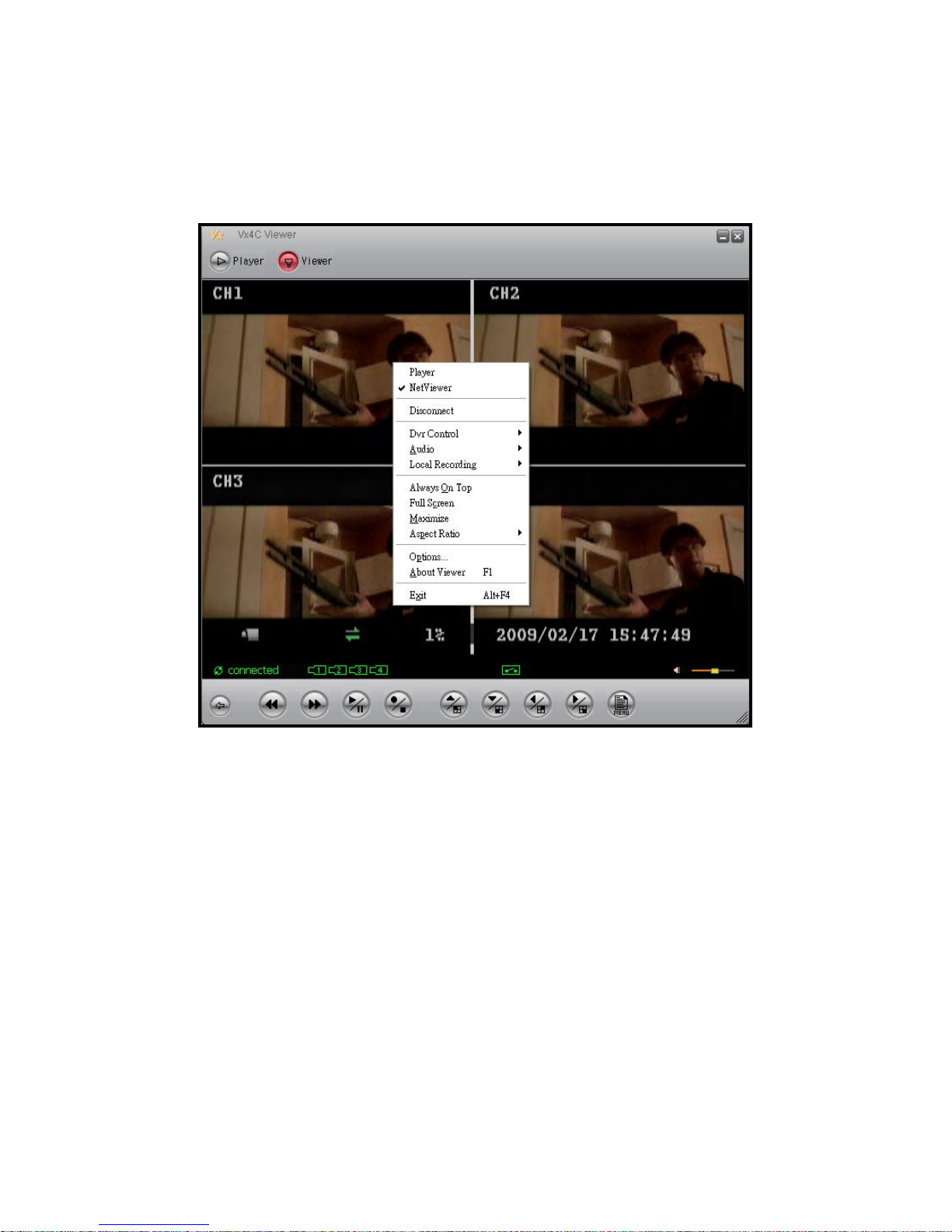
Right click on the Viewer window, viewer drop down menu appears (corresponding
configuration setup can be done).
Player: Switch to Player window.
NetViewer: Switch to NetViewer remote connection window.
Disconnect/ Connect: Select “Disconnect” option under connection status or
“Connect” option under disconnection status.
DVR Control: Similar to DVR front panel control button.
Audio: This function is not supported.
Local Recording: Save LIVE video to the PC HDD directory.
Always On Top: Setup window display to always be on top.
Full Screen: Switch to full screen mode.
Maximize: Enlarge the screen display to the maximum size.
Aspect Ratio: Force display aspect ratio to 640x448 or 640x544.
Options: Viewer option setup.
About Viewer: Display Viewer version.
Exit: Exit Viewer.
Page 53
52
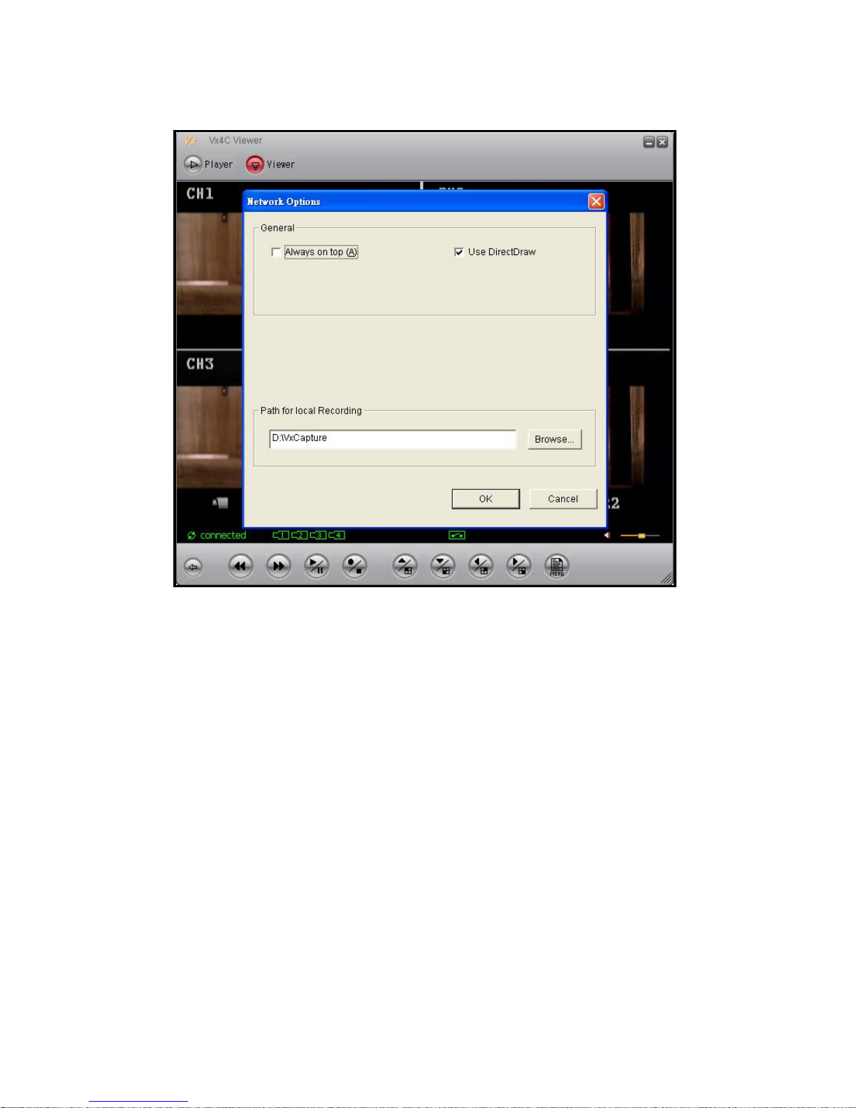
Viewer Network Options Setup
Always On Top: Setup window display to always be on top.
Use DirectDraw: Enable DirectDraw to accelerate image processing functions (Your
operating system and graphic hardware must support DirectDraw).
Path for local recording: Save LIVE video to the PC HDD directory.
Page 54
53
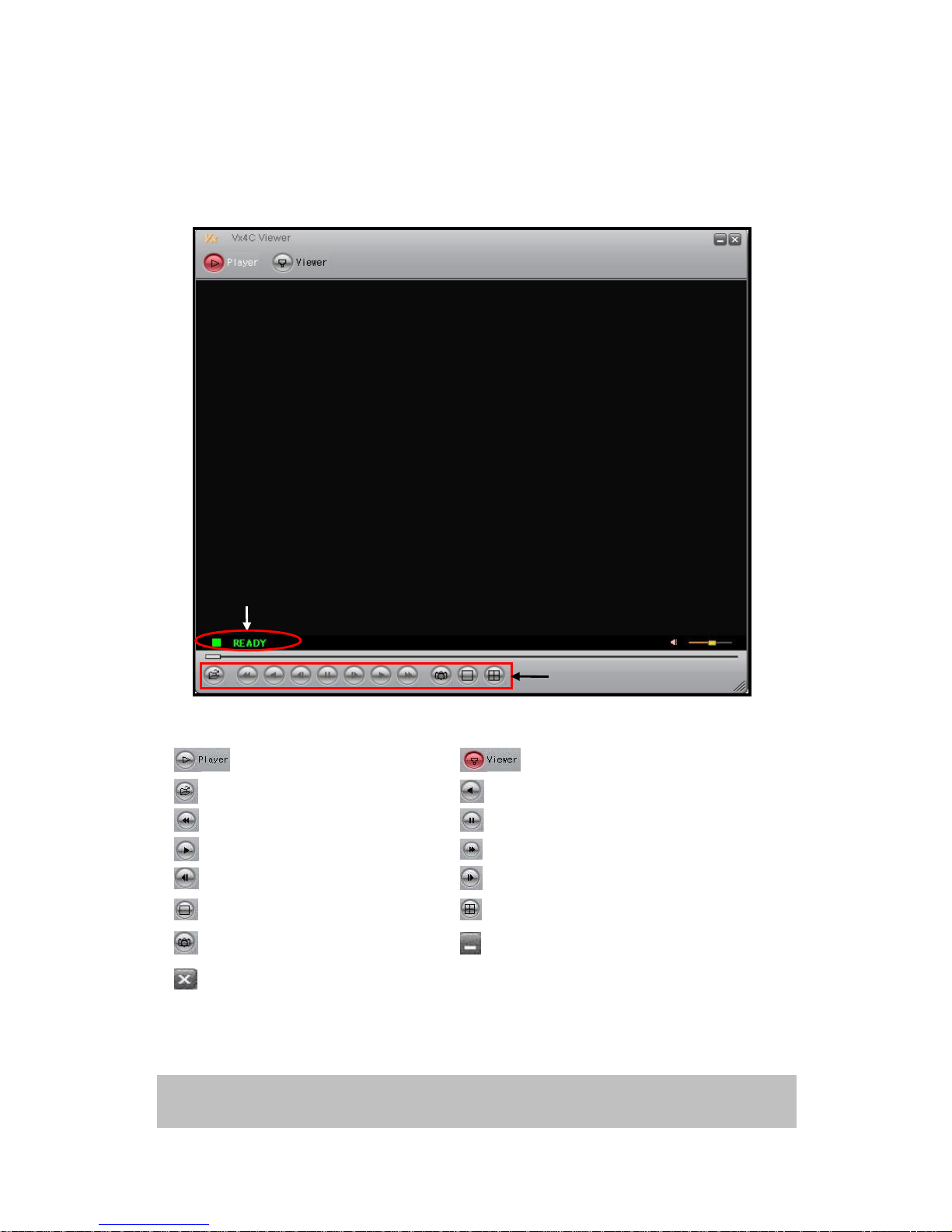
3. Player Guide
After the software installation has been completed, open-up Vx4CViewer. Move the cursor
to [Player] and then left click to enter Player user operating interface, as show below:
Player Panel Description
Press this button to enter player
window.
Press this button to enter DVR Viewer
connection window.
Open file.
Rewind.
Fast Rewind.
Pause.
Play.
Fast Forward.
Step Rewind.
Step Forward.
Switch to CH1/ CH2/ CH3/ CH4
full screen display.
Switch to 4-split screen display.
Press to perform video snapshot.
Press this button to minimize Player
window.
Press this button to close Player.
Mouse
Right
Button
Activate Player setup menu.
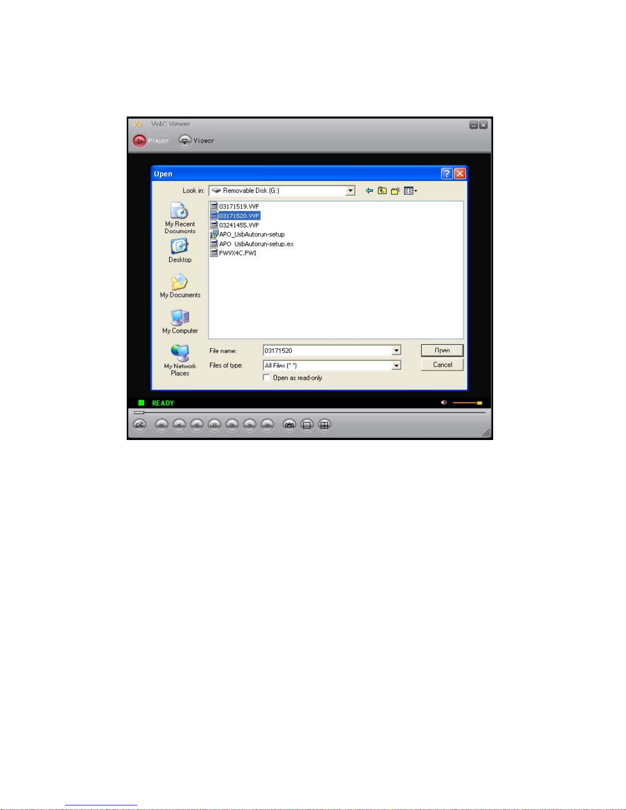
3.1 Open-Up Player File
NOTE: Playback Speed: 1x, 8x, 16x, 32x, 64x and 128x
Player Status
Page 55
54
Press [Open] button to open-up file, a folder appears and you may select a file from the
folder to playback.
Page 56
55
3.2 Player Control
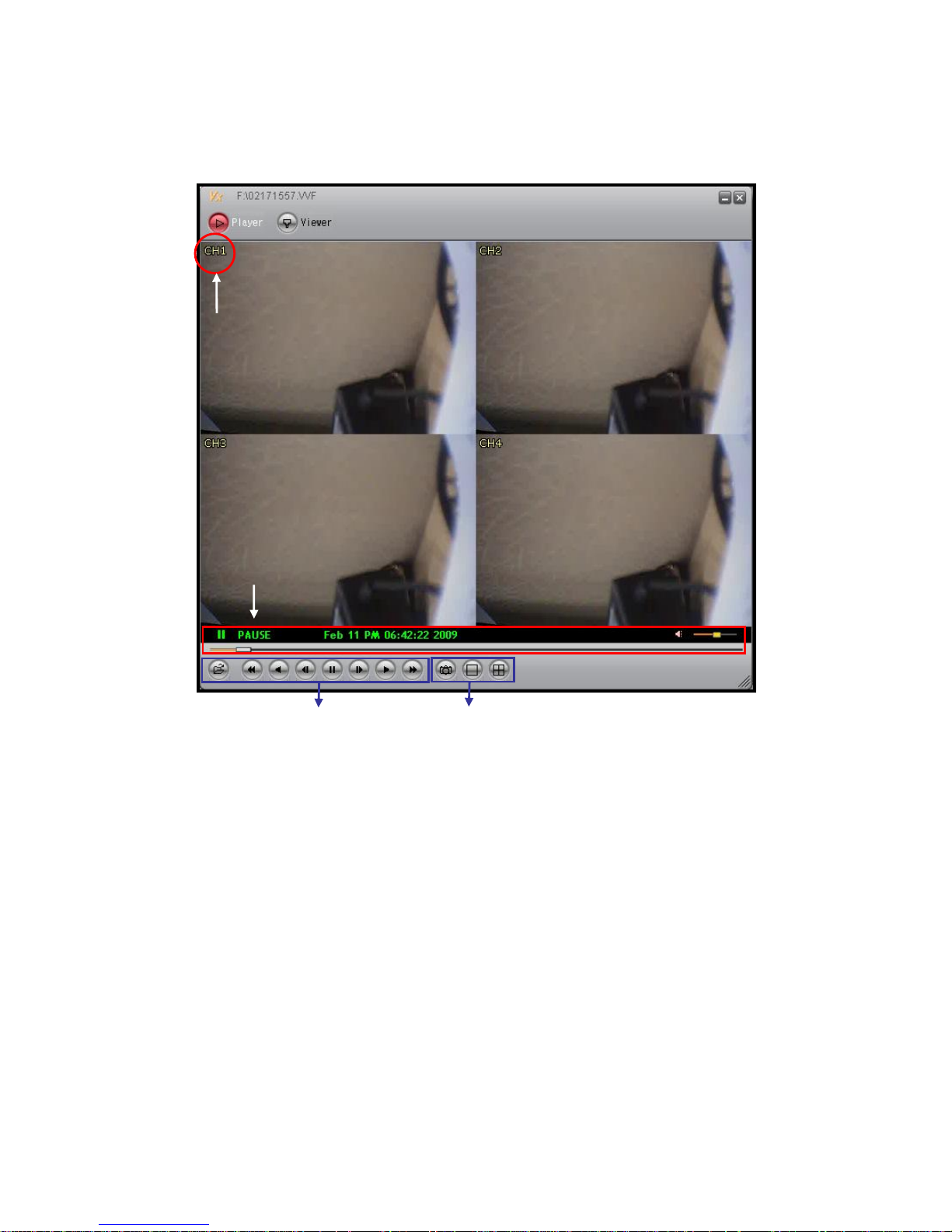
Player Main Display
Chanel Display: Show channel name of the current playback file. Use right-click menu
to Enable/ Disable the function.
Playback Status: Current playback speed and related time information.
Playback Control Button: Control buttons to proceed file Playback, Pause and Fast
Forward.
Snapshot and Channel Switching Button: To switch between Single-Full screen and
4-Split screens, also saves player snapshot to specified directory.
Playback Control Button
Playback Status
Snapshot and Channel Switching Button
Channel Display
Page 57
56
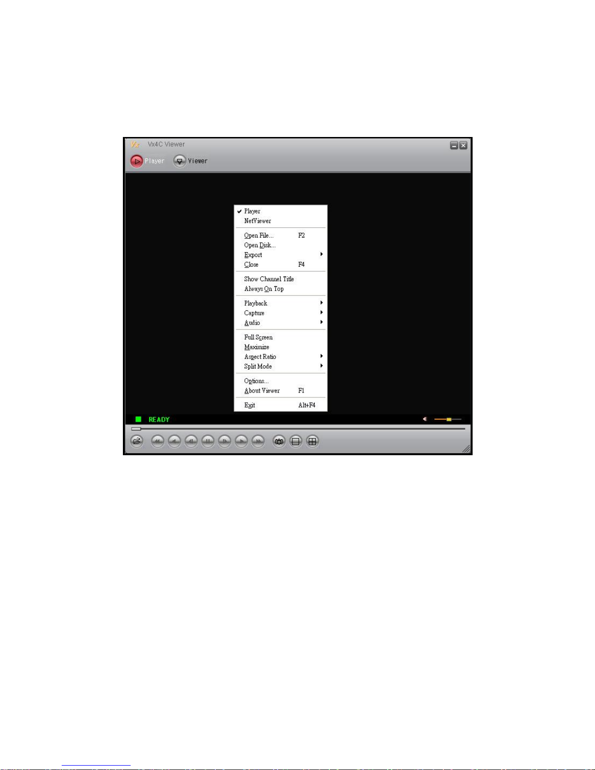
3.3. Player Setup
Right click on the Player window, player drop down menu appears (corresponding
configuration setup can be done).
Player: Switch to Player window.
NetViewer: Switch to NetViewer remote connection window.
Open File: Open-up a file.
Open Disk: Open-up a disk.
Export: Save the file as AVI format (this function is only effective when playback is faused).
Close: Close-up a file.
Show Channel Title: Display channel title.
Always On Top: Setup window display to always be on top.
Playback: Playback control function.
Page 58

57
Capture: Use this function to capture a certain part of the file and save it into a separate
file. Application method: First move to the stating point that you wish to retrieve. In the
player drop down menu, click item “CaptureÆ Mark In” and then move to the ending
point, click item “CaptureÆMark Out”. Finally click item “Capture Æ Export” to
decide the disk storage location and file name.
Audio: Volume adjustment.
Full Screen: Switch to full screen mode.
Maximize: Enlarge the screen display to the maximum size.
Aspect Ratio: Force the display aspect ratio to 640x448 or 640x544.
Split Mode: Switch to single channel or 4-split screen display.
Options: Player option setup.
About Viewer: Display Viewer version.
Exit: Exit Viewer software.
NOTE: When using Export function to convert file to AVI format, the encoding format used is
Xvid MPEG4 compression format. The system or playback software must support Xvid codec or
other compatible MPEG4 codec to playback converted AVI files. You can go to the following
website to download Xvid codec: http://www.xvid.org
Page 59
58
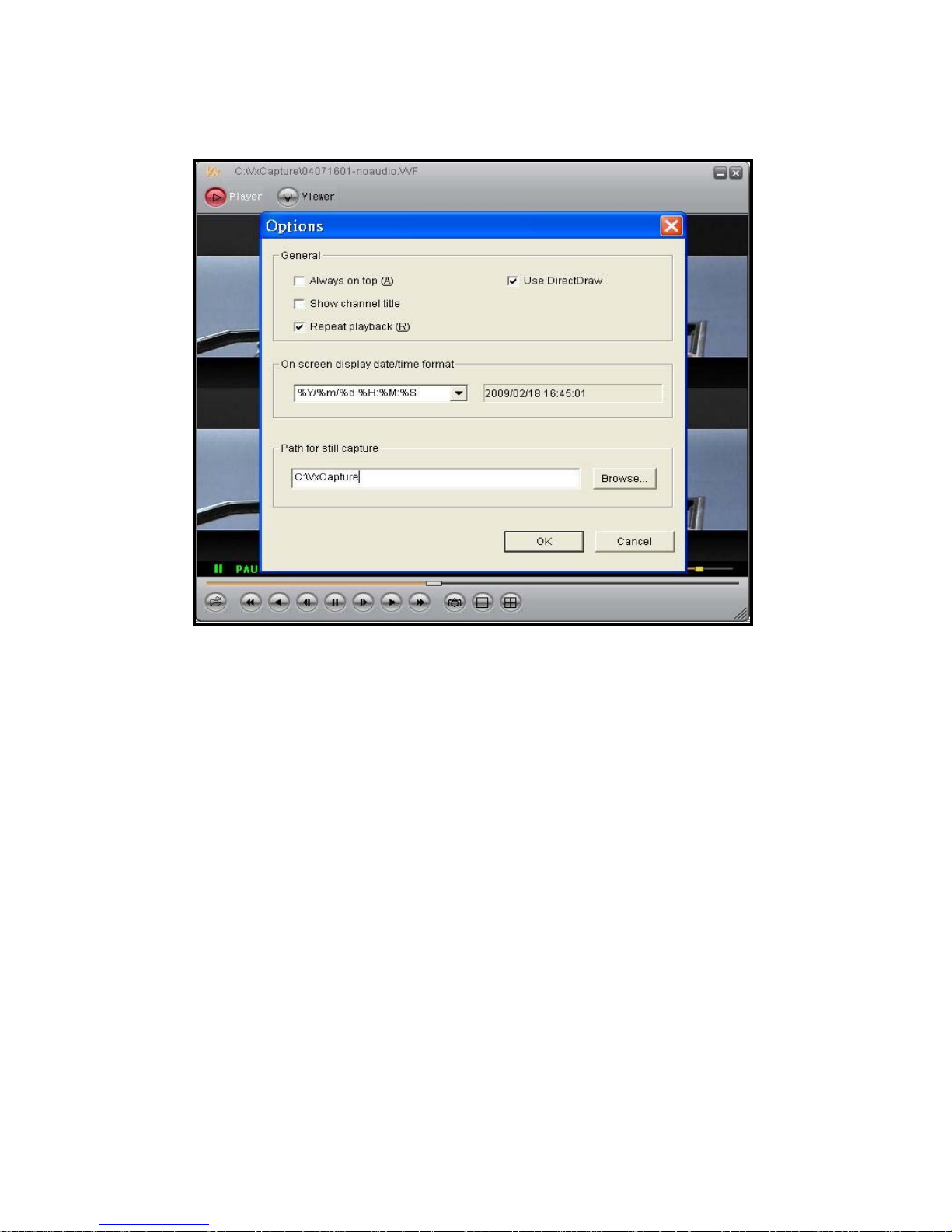
Player Options Setup
Always on top: Setup window display to always be on top.
Use DirectDraw: Enable DirectDraw to accelerate image processing functions (Your
operating system and graphic hardware must support DirectDraw).
Show channel title: Display channel title setup.
Repeat playback: Repeat playback function setup.
On screen display date/time format: To change the time display format.
On Screen Display Date/ Time Format Description:
1. %Y/%m/%d %H:%M:%S
Year (4 Units)/ Month/ Day Time (24 Hours): Minuit: Second
2. %y/%m/%d %H:%M:%S
Year (2 Units)/ Month/ Day Time (24 Hours): Minuit: Second
3. %Y/%m/%d %p %I:%M:%S
Year (4 Units)/ Month/ Day Time (12 Hours): Minuit: Second
4. %y/%m/%d %p %I:%M:%S
Year (2 Units)/ Month/ Day Time (12 Hours): Minuit: Second
5. %b %d %H:%M:%S %Y
Month Day Hour (24 Hours): Minute: Second Year (4 Units)
6. %b %d %p %I:%M:%S %Y
Month Day Hour (12 Hours): Minute: Second Year (4 Units)
Path for still capture: Setup the path for still captures.
Page 60
59
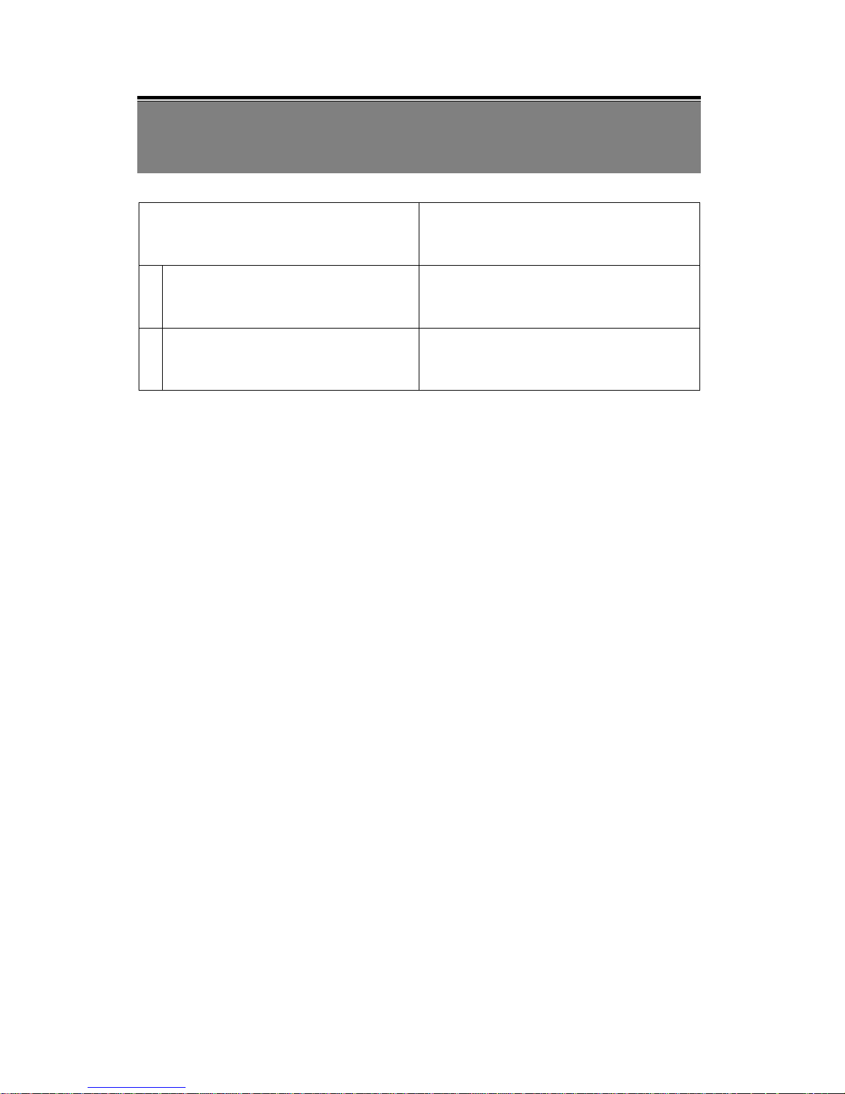
11. TROUBLESHOOTING
Question Answer
1 What brands of hard drives can I use? WD, Seagate, and Hitachi.
2
Which storage capacity of a USB
storage device is suggested?
8G and below.
Page 61
60
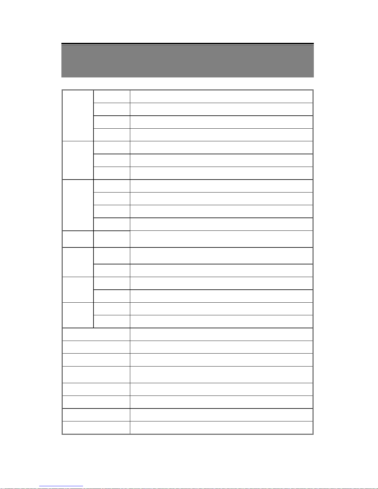
12. SPECIFICATION
Format
NTSC / EIA or PAL / CCIR
Compression MJPEG
Input
4 CH, BNC
Video
Output
1 CH BNC
Resolution 720x480 (NTSC), 720x576 (PAL)
Frame Rate Max. 120 / 100 IPS (NTSC / PAL)
Display
Division Single, Quad
Resolution 640x224 (NTSC), 640x272 (PAL)
Frame Rate Max.60 / 50 IPS (NTSC / PAL)
Quality High / Normal / Low
Recording
Mode Manual / Schedule / Motion Detection
HDD Basic Storage
1x3.5” SATA HDD
(Max.1TB)
Triggered
Mode
Motion Detection, Video Loss
Alarm
Action Recording, Sound Alert
Ethernet 10/100 BaseT Ethernet (RJ-45)
Network
Protocol TCP/IP, DDNS, , ICMP, ARP, DHCP
Input 1CH, RCA
Audio
Output 1CH, RCA
Backup Device USB
Post Alarm 1 ~ 60sec
Search Method By Date, Time, Event
Power Supply
AC100~240V 50/60 Hz,
DC12V / 2.5A
Weight 2.5 Kg (without HDD)
Dimensions (WxHxD) 195X45X226mm
Operating Environment 30 ~ 80% RH, 5°C ~ 40°C (41°F ~ 104°F)
Remote Control IR Transmission
Page 62

61
MEMO
 Loading...