

Page 1

DVQ-2, DMR8RT, DMR16RT
QUICK-START GUIDE
IMPORTANT!!!
PLEASE READ BEFORE OPERATING YOUR DVR
Ready to go, right out of the box!
This digital video recorder is designed to function right out of the box. We made setting
up your DVR easier by adjusting the time, date and record settings for you. Your DVR is
set to record for 14 days with the video quality and frame rate set to the highest settings
for 14 days of recording.
Trouble Shooting
Inside this quick-start guide are easy to use techniques for the following symptoms:
• Not showing video, follow the steps 1 - 5 below in this manual.
• HDD (Hard drive) error messages follow the steps 1 - 5 below in this manual.
• HDD not found, follow the steps 1 - 5 below in this manual.
• All video camera images are distorted, follow the steps 1 - 5 below in this
manual.
• DVR will not record; follow the steps 1 - 5 below in this manual.
• DVR is not showing proper date & time, follow step 3 below in this manual.
Networking your DVR
View video from your PC anywhere in the world by connecting your DVR LAN
connection to your network system. See Networking on page 8.
1
Page 2

Advance Settings
If you need to adjust recording time, frame rate or quality refer to the main user manual
also included with this DVR.
Quick-Start Guide Contents
Also, in this quick-start guide is instructions on how to do the following:
1. Run Factory Default …………..p 5
2. Set up Proper Time & Date…...p 6
3. Clear Hard Drive………………. p 6
4. Set up OVERWRITE Function...p 7
5. Networking your DVR…………..p 8
NOTE: After running the above settings, please refer to RECORD SETTINGS in your
user manual.
Optimizing Your DVR
1. It is important that you setup your DVR to meet your needs. Key points of
consideration include: recording time, frames per second, naming your cameras, and
setting motion detection. Please see your user’s manual for detailed set-up
instructions.
DON’T FORGET: Supercircuits offers FREE lifetime tech support on every
product we sell.
2
Page 3

1. Please follow the steps below to repair YOUR DVR
1. Connect your monitor to the DVR monitor output jack. The back of your DVR could be
different from the below diagram.
DVR Monitor Installation
Turn your DVR on and press the “MENU” key on the front panel to enter the main menu list. The
Menu allows you to configure your DMR settings.
DVQ-2
3
Page 4

DMR- 8 & 16 RT
The DVR will ask you for a password.
The password screen will appear:
Password: 0000
The default admin password is 0000. Enter the default password, and press the “ENTER” key.
Note: If you get a message “Password Error”, you have entered an incorrect password.
• Up and Down keys: Scroll up and down.
• Left and Right keys: Scroll left to right within a menu option.
• ENTER: Selects a submenu / an option under a submenu for browsing / modification
• MENU: Completes modification of a menu option; exits a menu.
• + Plus and – Minus keys are used to change values.
MAIN MENU
There are 4 options available in the Main Menu:
MENU
RECORD
TIMER
DATE
ADVANCE
4
Page 5

2. RUN FACTORY DEFAULT
SYSTEM RESET
Go down to ADVANCE and hit the >ENTER key, select SYSTEM and hit the ENTER key.
MENU
RECORD
TIMER
DATE
ADVANCE
CAMERA
DETECTION
DISPLAY
ALERT
REMOTE
SYSTEM
ADVANCE SYSTEM
Select RESET DEFAULT and > hit the ENTER key.
You will see a RESET DEFAULT dialog box. Reset all system
settings to factory default settings. Change the NO option to YES by
hitting the >LEFT arrow key and hitting the ENTER key.
Wait for 1 to 2 minutes and you will see a REBOOT dialog box and the system will reinitialize.
Go back to the main MENU and select DATE.
NETWORK
BACKUP
HDD INFO
EVENT LOG
SYSTEM
SERIAL TYPE RS-485
BAUD RATE 02400
HOST ID 001
IR ON
PASSWORD SETUP
RESET DEFAULT RESET
CLEAR HDD EXT 003
UPGRADE NO
R.E.T.R. (MIN) 03
AUTO KEYLOCK NEVER
LANGUAGE ENGLISH
VERSION 1088-10-K2-04-AA-11
VIDEO FORMAT NTSC
RESET DEFAULT
RESET DEFAULT
ARE YOU SURE ?
YES NO
5
Page 6

3. TIME/ DATE SETUP
Set up the DVQ system time by selecting DATE in main MENU and hit
the Enter key.
MENU
RECORD
TIMER
DATE
ADVANCE
You will see your TIME/DATE settings, enter correct date and time.
DATE
DATE 2007 MAR 14 11:05:59
FORMAT Y-M-D
DAYLIGHT SAVING OFF
Hit >MENU key once to exit and move on to CLEAR HDD.
4. CLEAR HDD
Select ADVANCE from main MENU, hit the >ENTER key and scroll down to SYSTEM and hit the
>ENTER key.
MENU
RECORD
TIMER
DATE
ADVANCE
Scroll down to CLEAR HDD and hit
the >ENTER key.
ADVANCE SYSTEM
CAMERA
DETECTION
DISPLAY
ALERT
REMOTE
SYSTEM
NETWORK
BACKUP
HDD INFO
EVENT LOG
SYSTEM
SERIAL TYPE RS-485
BAUD RATE 02400
HOST ID 001
IR ON
PASSWORD SETUP
RESET DEFAULT RESET
CLEAR HDD EXT 003
UPGRADE NO
R.E.T.R. (MIN) 03
AUTO KEYLOCK NEVER
LANGUAGE ENGLISH
VERSION 1088-10-K2-04-AA-11
VIDEO FORMAT NTSC
6
Page 7

You will see a dialog box with “CLEAR HDD ARE YOU SURE? YES OR NO”. Hit the LEFT key
Y
to select YES and hit the >ENTER key.
You will see another dialog box asking for confirmation “CLEAR HDD
CLEAR OK “ hit the ENTER key. This option will delete all the contents of
your HDD.
You will be back to the SYSTEM menu after clearing the HDD. Hit the MENU key twice to exit
SYSTEM and ADVANCE sub menus. Scroll up to the RECORD menu option to setup your
OVERWRITE setting.
CLEAR HDD
CLEAR HDD ARE YOU SURE?
YES OR NO
CLEAR HDD
CLEAR OK
OK
5. Setup OVERWRITE function
HDD OVERWRITE
Select RECORD in the main MENU and Scroll down to OVERWRITE and hit the ENTER or –
minus or + plus key to enter OVERWRITE function.
MENU
RECORD
TIMER
DATE
You will see a dialog box wanting confirmation
“START OVERWRITE ARE YOU SURE, YES NO,
select YES and hit the >ENTER key.
NOTE: In OVERWRITE RECORDING mode, over writing of previous files will occur when the
hard drive is full.
Hit the MENU key twice to exit the menu settings. Turn your DVR off by hitting the >POWER
button and unplugging the DVR for about 15 to 20 sec’s. Turn the unit on and your ready to start
installing and configuring the rest of your system.
RECORD
MANUAL RECORD ENABLE
EVENT RECORD ENABLE
TIMER RECORD ENABLE
OVERWRITE
RECORD IMG SIZE
RECORD QUALITY
MANUAL RECORD IPS
EVENT RECORD IPS
TIMER RECORD IPS
TOTAL IPS SHARE
OVERWRITE
START OVERWRITE ARE YOU SURE
ES NO
7
Page 8

NETWORKING
View video from your PC anywhere in the world by connecting your DVR LAN connection to your
network system.
Things to do before networking your DVR
1. Connect DVR LAN connection to your LAN router.
2. To connect to the world wide area network for remote viewing you must configure your
router to allow port forwarding. Super Circuits does not provide technical support for router
setup. Contact your service provider/router manufacturer for support on setting up port
forwarding. Use port number 8000.
3. Do you have a dynamic or static IP address? Note: Static IP address is highly
recommended, because of the video connection reliability. Call your IP provider about
setting up a static IP address for your DVR.
4. Make sure you have DirectX version 9.0c on your computer. If not go to
www.microsoft.com/directx
5. Make sure that you have the following information from your IP provider or IT department:
A. IP address.
B. Subnet Mask.
C. Default Gateway.
D. If there is a DNS number.
E. If DHCP settings are allowed set your DVR to “Manual” not “Automatic”.
G. Next verify your IP address (for your domain) by going to www.whatismyip.com.
is the IP address you will use to log in remotely
This
8
Page 9

Setting up your DVR for networking
6. Access your DVR network settings by going to MENU / ADVANCE/ NETWORK. Set IP
ADDRESS, GATEWAY, NETMASK and WEB PORT.
MENU
RECORD
TIMER
DATE
ADVANCE
7. Change NETWORK TYPE to STATIC by
hitting the + plus or – minus keys and hit the
ENTER key.
8. Enter your IP, Gateway and Netmask and hit
the MENU key to exit STATIC menu.
9. In NETWORK menu select DNS and enter IP
address of the domain server obtained from
your ISP (Internet Service Provider).
10. Select PORT and enter 8000 and exit
NETWORK menu.
11. Exit all menus and turn your DVR off by hitting the power key and holding for about 3
seconds.
ADVANCE SYSTEM
CAMERA
DETECTION
DISPLAY
ALERT
REMOTE
SYSTEM
NETWORK
BACKUP
HDD INFO
EVENT LOG
NETWORK
NETWORK TYPE STATIC
DNS 168. 95.
PORT 0080
NETWORK
NETWORK TYPE STATIC
DNS 168. 95. 1. 1
PORT 8000
STATIC
IP 160 . 121 . 346 . 236
GATEWAY 160 . 121 . 346 . 236
NETMASK 255 . 255 . 255 . 254
NETWORK
NETWORK TYPE STATIC
DNS 168. 95. 1. 1
PORT 8000
NETWORK
NETWORK TYPE STATIC
DNS 168. 95. 1. 1
PORT 8000
9
Page 10
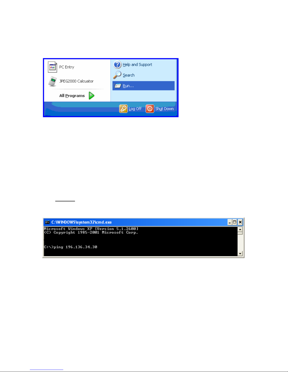
Test your connection
12. Return to your computer: go to the PC start menu and select “Run”
13. Type “cmd” and click “OK”.
14. A black box
prompt, space bar and the IP address of the DVR and then click “>ENTER.
Fig1:
will pop up with a “C” prompt. After the “C” prompt type “ping” at the dos
15. A box will pop up and it will display “reply from” the IP address 3 to 4 times. You will also see
“Packets sent = X, Received = X and Lost = X. This will tell you that, you’ve successfully
connected to your DVR and we can proceed. Like FIG.2 below.
10
Page 11
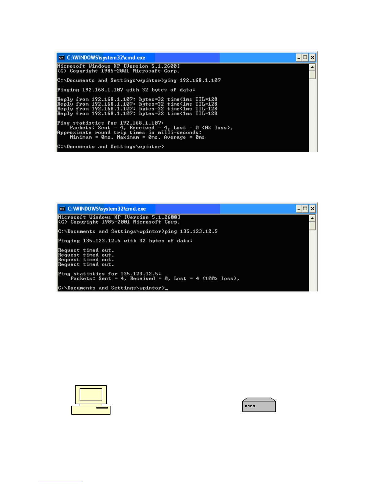
FIG.2
If you’re seeing “Request timed out” and “Packets: Sent X, Received = X, Lost = X” like FIG.3
below, then you have not established a LAN connection between the DVR and the computer.
You will need to recheck all DVR network settings above, check with IP provider or IT
department, router settings. Make sure cables are good, and connected.
FIG.3
This could also be due to a bad cable between the DVR and router or bad DVR Network Interface
Controller (NIC). Check the Ethernet cable connection on the back of the DVR and check for
green lights and that they blink when you “ping” the DVR. If it is not blinking, this could indicate
that the DVR’s network interface card is bad and call us for tech support. If green light is blinking,
as a final check, connect the DVR directly to the computer using an Ethernet “crossover cable”
(which is available at any electronics store such as Radio Shack, or Best Buy, Circuit City, etc…)
eliminating all other cables and equipment. Crossover cables are only used for testing purposes.
And repeat the pinging process. If after connecting the crossover cable and you are successful in
pinging your DVR, the problem is with your router, cables or the IP address. Check with your IP
provider, check your cables and make sure your router is configured for port forwarding. If you’re
not successful in pinging your DVR call Supercircuits for technical help.
---------------------------------------------------------------
PC Ethernet Crossover Cable DVR
11
Page 12
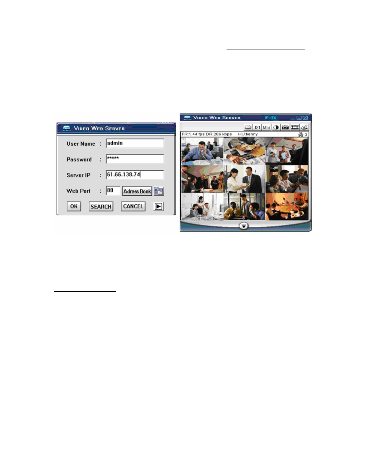
16. If you’re looking at FIG.2 then you have demonstrated that a Local Area Connection (LAN)
has been made between the DVR and the computer. Proceed to Software installation.
17. Install the CD that came with your DVR into the PC and install Video Web Server.
18. Double click Video Web Server "
and Port 8000 and hit OK.
NOTE: Factory default user name is ADMIN, Password is ADMIN.
Icon enter User Name, Password, IP address
Who to Contact
If you have any further questions setting up your DVR, or are experiencing any issues
with your DVR, please contact our dedicated technical support experts at:
Technical Support: 800-335-9777 Press 3 for Technical Support
Hours of Operation: Monday thru Saturday: 9am-5pm
12
Page 13
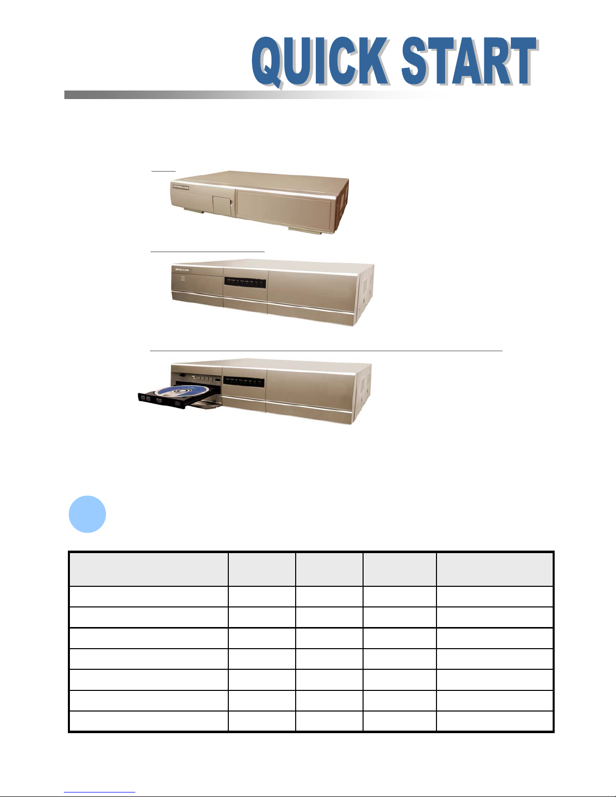
Make Sure Your Package Contains :
Make Sure Your Package Contains :
1
1
16 / 8 / 4 CH Real Time MPEG-4 Network DVR
151
16CH / 8CH / 4CH
16CH / 8CH / 4CH
4CH
4CH
16CH / 8CH / 4CH Built
16CH / 8CH / 4CH Built--
in DVD
in DVD--
RW Writer or CD
RW Writer or CD--
RW Writer
RW Writer
MPEG4 DVR SERIES_V1.1
Please read instructions thoroughly before operation and retain it for future reference.
ˇˇˇˇ
Digital Video Recorder
ˇˇˇˇ
Screws
ˇˇˇˇ
DSUB PIN Connector
ˇˇˇˇ
Power and Data Bus
ˇ
Optional
ˇˇ
IR Transmitter and IR Receiver
ˇˇˇˇ
Licensed Software AP
ˇˇˇˇ
Adapter
16CH / 8CH / 4CH
DVD-RW / CD-RW
4CH8CH16CHMODEL
1
Page 14
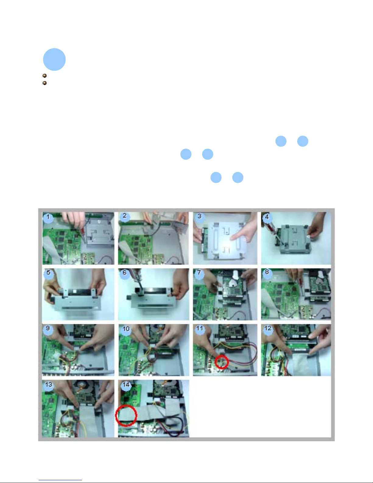
Install HDD :
Install HDD :
2
2
16CH / 8CH
16CH (D) / 8CH (D) / 4CH (D)
2
Carefully follow the steps to ensure correct installation.
*** Note: If you want to install two HDDs, please set one HDD to “Master Mode” or “Single
Mode”, and the other one to “Slave Mode”. ***
1) Open the upper cover of the DVR and screw out the bracket.
2) Screw HDD to the HDD bracket.
3) Connect the HDD to the power connector and IDE BUS (make sure to align
the HDD precisely to the pin connection).
4) Close the upper cover of the DVR.
3
3
8
8
~
1
1
2
2
~
9
9
14
14
~
Page 15
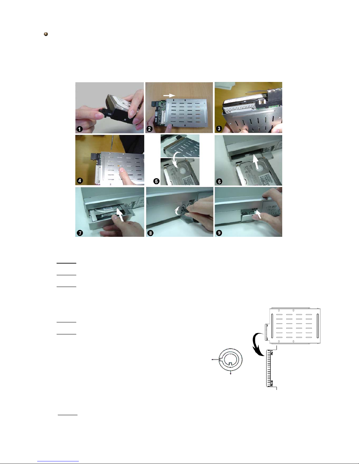
3
••Step 1
Step 1
Connect the connector with the HDD (Pic. 1).
••Step 2
Step 2
Put HDD into the HDD cartridge with the pins facing outside (Pic. 2).
••Step 3
Step 3
Fasten the HDD to the cartridge. Before you fasten the HDD, please be aware
that you must to align the pins of the HDD with the pin marks of the cartridge. Then
fasten the HDD correctly (Pic. 3 & 4). You must precisely align the hard disk to the pin
connection to ensure correct installation.
••Step 4
Step 4
Reverse the HDD and put it into DVR (Pic. 5, 6 & 7).
••Step 5
Step 5
Lock the HDD slot by turning the key clockwise (Pic. 8).
A ( locked )
B ( unlocked )
••Step 6
Step 6
Close the cap (Pic. 9).
4CH
Carefully follow the steps to ensure correct installation.
*** Note: Please set one HDD to “Master Mode” or “Single Mode” ***
Note : If you do not lock the HDD cartridge the DVR system will not function properly.
Page 16
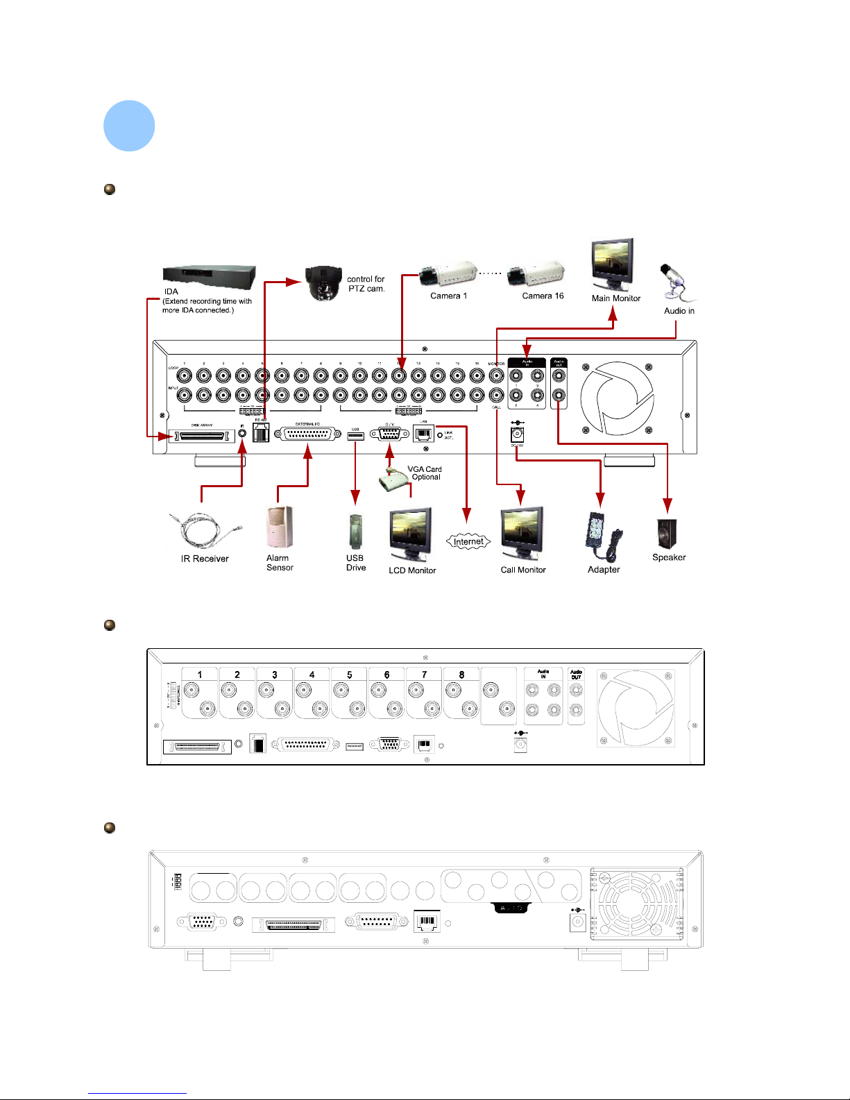
Physical Connections :
Physical Connections :
3
3
DC 19V
INPUT
DISK ARRAY
LOOP
RS485
INPUTIRINPUT INPUT
EXTERNALI/O
USB
INPUT
LOOP3LOOP LOOP LOOP
INPUT
D/V
LAN
INPUT
ACT.
LINK
INPUT
CALL
LOOP LOOP LOOP
MONITOR
31
24
8CH / 8CH (D)
INPUT
2
LOOP
DC 19V
LOOP LOOP
3
INPUT
4
INPUT
ACT.
LAN
2
LINK
CALLMONITOR
IN
1
4
3
OUT
INPUT
D/V
1
HI-IMPEDANCE
4
75?
1
LOOP
EXTERNAL I/O
DISK ARRAY
IR
4CH / 4CH (D)
Take 16CH / 16CH (D) as an example
4
Page 17

Before using this unit, please set up the system time first in order to process the
functions correctly.
Æ Press “MENU” button to enter menu list
Æ Enter the default password “0000” to unlock keys
Æ Go to “DATE” menu and set the date
Æ Press “+”or “-” button to set the correct time of the DVR
Æ If users would like to activate the daylight saving function, please turn the
daylight saving function “ON” and press “ENTER” button to enter the daylight
saving setting page.
Æ After setting, please press ” MENU ” to exit
System Time Setup :
System Time Setup :
4
4
DATE
DATE
DATE 2006-MAR-28 14:30:00
FORMAT Y-M-D
DAYLIGHT SAVING ON
DAYLIGHT SAVING
DAYLIGHT SAVING
ON 4TH-SUN-MAR 01: 00: 00
OFF 4TH-SUN-OCT 01: 00: 00
ADJUST 01 : 00
NOTE: The illustrated setting means: During the daylight saving time period (start from the 4
th
Sunday of March, end on the 4thSunday of October), the DVR system time will plus one hour.
Record & Playback :
Record & Playback :
5
5
RECORD
RECORD
MANUAL RECORD ENABLE
EVENT RECORD ENABLE
TIMER RECORD ENABLE
OVERWRITE
RECORD IMG SIZE
RECORD QUALITY
MANUAL RECORD IPS
EVENT RECORD IPS
TIMER RECORD IPS
TOTAL IPS SHARE
Record:
Record:
16CH / 8CH: “RECORD”
16CH (D) / 8CH (D) / 4CH (D): “RECORD”
4CH: “REC”
5
Page 18

Playback:
Playback:
Press “ PLAY ” button, and the DVR will playback the last recorded video.
• FAST FORWARD (F.F. ) & FAST REWIND (REW) :
• PAUSE / IMAGE JOG:
•STOP:
• CHANNEL SHIFT
(Display Mode, Full Screen Switch, and Channel Display Switch)
• SLOW PLAYBACK
• AUDIO
16CH / 8CH: “SHIFT” + “SET”
16CH (D) / 8CH (D) / 4CH (D): “SHIFT” + “SET”
4CH: “SET”
16CH / 8CH: “SHIFT” + “SLOW”
16CH (D) / 8CH (D) / 4CH (D): “SHIFT” + “SLOW”
4CH: “SLOW”
16CH / 8CH: “SHIFT” + “AUDIO”
16CH (D) / 8CH (D) / 4CH (D): “SHIFT” + “AUDIO”
4CH: “”
Backup :
Backup :
6
6
BACKUP
BACKUP
USB BACKUP
USB BACKUP~ FOR 16CH / 8CH / 4CH and 16CH (D) / 8CH (D) / 4CH (D)
6
USB BACKUP
USB BACKUP
START TIME 2006-05-12 16 : 00 : 00
END TIME 2006-05-12 21 : 00 : 00
AVAILABLE SIZE 0512 MB
CHANNEL
● 01 ● 02 X 03 X 04
X 05 X 06 X 07 X 08
X 09 X 10 X 11 X 12
X 13 X 14 X 15 X 16
HDD NUM MASTER
BACKUP TO USB START
Page 19

For detailed instructions, please refer to P.36 of the user’s manual.
7
DISK BACKUP ~ FOR 16CH (D) / 8CH (D) / 4CH (D)
Go to “MENU” Æ “ADVANCE” Æ “BACKUP”, and press ”ENTER”. The screen will
show the following options:
BACKUP
BACKUP
USB BACKUP
DISK BACKUP
Select “DISK BACKUP” and press “ENTER”.
DISK BACKUP
DISK BACKUP
START TIME 2006-05-12 16 : 00 : 00
END TIME 2006-05-12 21 : 00 : 00
AVAILABLE SIZE 4083 MB
CHANNEL
● 01 ● 02 X 03 X 04
X 05 X 06 X 07 X 08
X 09 X 10 X 11 X 12
X 13 X 14 X 15 X 16
HDD NUM MASTER
BACKUP TO DISK START
1) Press “+” and “-” buttons to open the DVD / CD WRITER.
Put the DISK into DVD / CD WRITER, and press “+”and “-” buttons again to close.
(NOTE: Use DVD
(NOTE: Use DVD--
R DISK only)
R DISK only)
2) Go to “DISK BACKUP” menu and set the start time, end time, channels and HDD number.
Only 4 channels support audio backup. If you want to backup images with audio, please connect
the camera to the correct channels.
16CH / 16CH(D) models: CH13, CH14 , CH15 and CH16
8CH / 8CH(D) models: CH5, CH6, CH7 and CH8
4CH / 4CH(D) models: CH1, CH2, CH3 and CH4
3) After setting up the backup information, move the cursor to “START”, and press “ENTER”.
While the files are backing up to DISK, users will see the backup completed percentage on the
screen.
4) After backup files to DISK, “DISK BURN FINISH” message will be prompted on the screen.
Press “+” and “-” to eject the DISK from DVD / CD WRITER.
5) Put DISK into the DVD / CD -ROM of your PC.
(O/S system: Windows XP and Windows2000).
And then double click the file Æ Convert the file
Æ Play the backup file at PC side.
NOTE:
The maximum number of backup files in the disk is 41.
Note:
Select channels by pressing “ENTER” button to change the symbol in front of the
channel number.
Symbol “X” means that this channel is not selected.
Symbol “●” means that this channel is selected.
Page 20

There are two ways to make network setup: via your DVR locally or via the licensed
AP interface.
NETWORK
NETWORK
NETWORK TYPE STATIC
DNS 168. 95. 1. 1
PORT 0 0 8 0
STATIC
STATIC
IP 60
. 121. 46. 236
GATEWAY 60. 121. 46. 226
NETMASK 255. 255. 255. 254
Network Setup
Network Setup
7
7
Via DVR
Go to “MENU” Æ “ADVANCE” Æ “NETWORK”, and you will see a network setup
screen as follows:
There are three options for NETWORK TYPE: STATIC, DHCP and PPPoE. Select
one of the network type by pressing the button “+” or “-”, and press “ENTER” to go
to the submenu for further setup.
NETWORK TYPE: STATIC
After selecting STATIC as the network type, press “ENTER” and you will see a
setup screen as follows. Enter IP, GATEWAY and NETMASK information needed in
the DVR by using the button “+” or “-”. Press “MENU” again to finish the setup.
NETWORK TYPE: DHCP and PPPoE
For DHCP and PPPoE settings, it’s recommended to set directly via the licensed
AP interface because more detailed information has to be set via this interface.
Please see P.9 for more details.
You also need to apply DDNS service to get a “Hostname” before using DHCP
and PPPoE network services. Please see at P.9 for more details.
8
Page 21
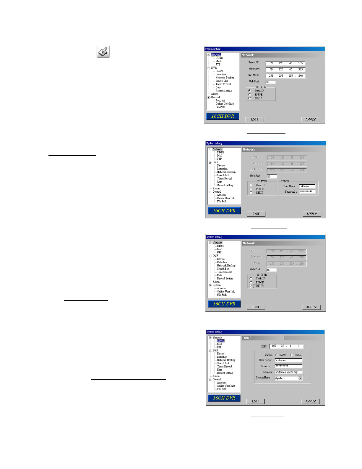
9
1. Static IP setup
2. PPPOE setup
3. DHCP setup
4. DDNS setup
Via Licensed AP
Choose the icon (SYSTEM CONFIG) from
the top control panel, and “System setting”
window will be shown. Choose “Network” and you
will see the screens from 1 to 3 on the right hand
side for different setting.
1. Static IP setup
Select “Static IP” from “IP TYPE” section, and
enter “Server IP”, “Gateway”, “Net Mask” and
“Web Port” (80~19999) information.
Press “APPLY” to confirm and finish the settings.
2. PPPOE setup
Select “PPPOE” from “IP TYPE” section. Enter
“User Name” and “Password” information
provided by your ISP (Internet Service Provider)
supplier, and type “Web Port” information
(80~19999).
Press “APPLY” to confirm and finish the settings.
Then, go to “Network” Æ “DDNS” for further setup
(See 4. DDNS setup
).
3. DHCP setup
Select “DHCP” from “IP TYPE” section, and enter
“Web Port” information (80~19999). Your router or
cable modem network needs to support DHCP
function.
Press “APPLY” to confirm and finish the settings.
Then, go to “Network” Æ “DDNS” for further setup
(See 4. DDNS setup
).
NOTE: Some router brands may require to restart
your DVR to get the IP address.
4. DDNS setup
Go to “Network” Æ “DDNS”.
To configure DDNS setup, please go to a website
(Ex: www.dyndns.org) which provides free DDNS
service and get a “Hostname” first. For details,
please check “DDNS APPLY EXAMPLE
” at P.38
in your user’s manual.
Enter “User Name”, Ppassword” and “Domain”
information, and select your DDNS system name
from “System Name” drop-down menu.
NOTE: When “AUTO” check box is selected, the
system will automatically get DNS information
from the Internet.
Page 22
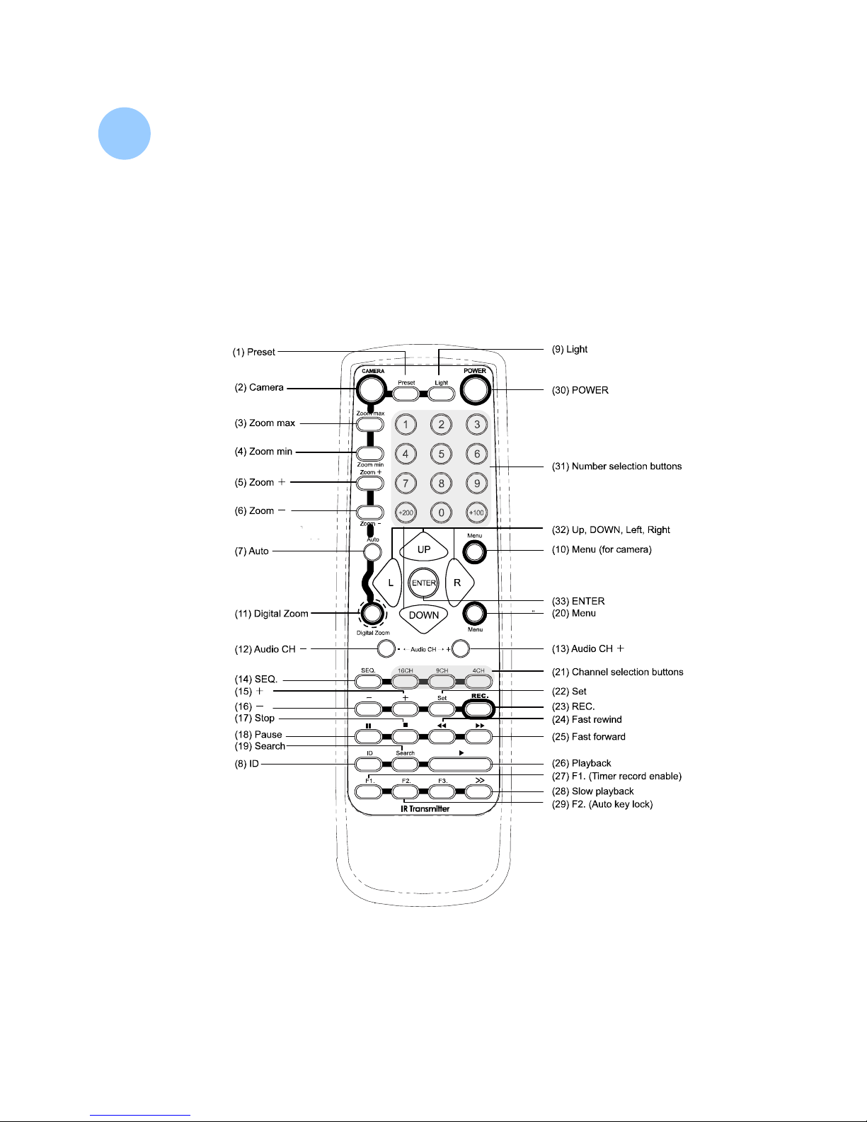
IR Transmitter :
IR Transmitter :
8
8
* CAMERA control buttons: Button (1) to (10). (button (9) is used for controlling the switch)
* DVR control buttons: Button (11) to (29).
* OTHER control buttons: Button (30) to (33) (Support controlling both CAMERA & DVR).
* F3 is a dummy button.
* IR control for PTZ camera, DVR, and remote switch
* IR emission distance: straight line is 10m; transmit at left and right 22.5° is 8m
* Control up to 255 PTZ cameras and remote switch
* Enabling different ID
* Current consumption: AAA size battery × 2
10
Page 23
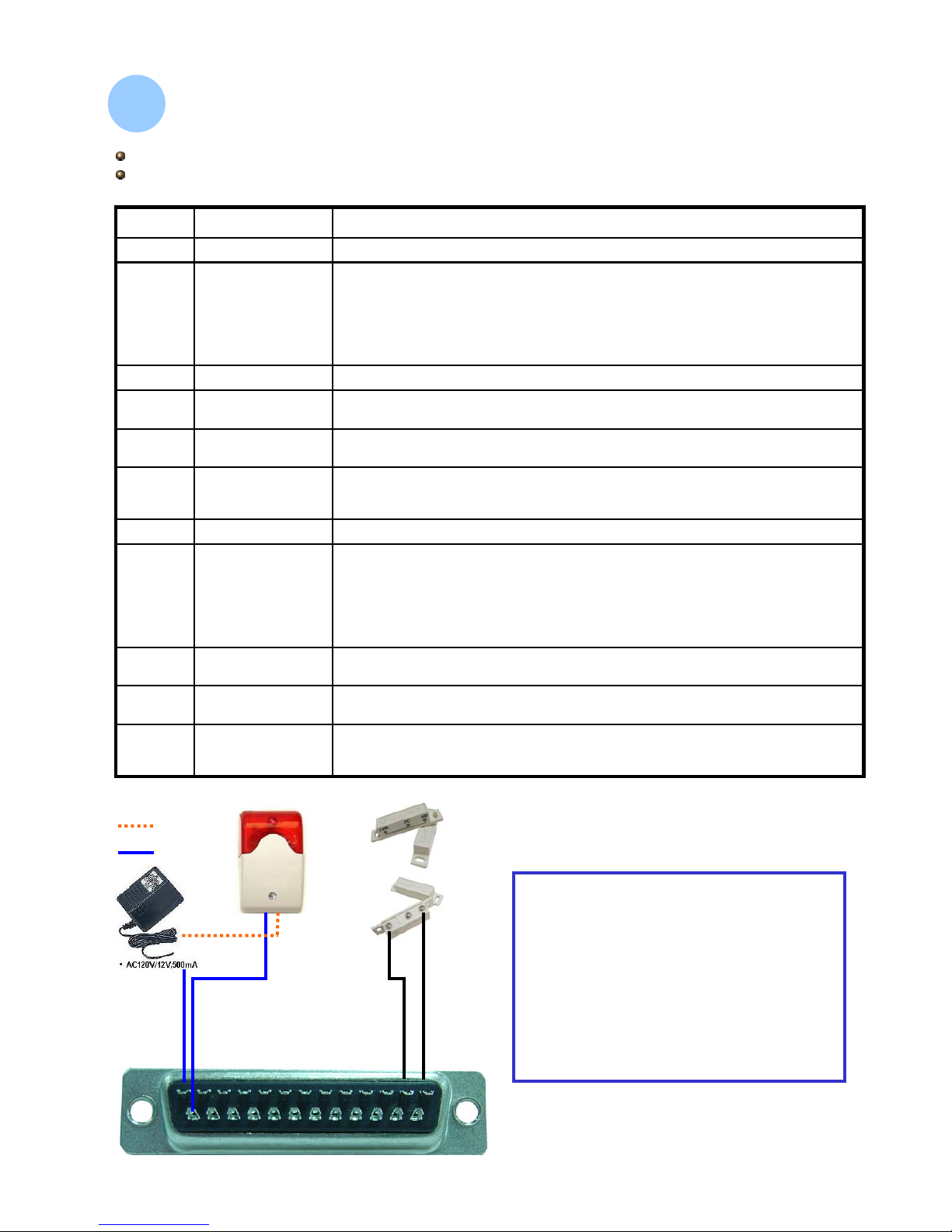
Under the normal operation, COM disconnects with NO. But when any alarm is
triggered, COM connects with NO.
Attention: The voltage restriction is under AV/DC 30V.
EXTERNAL
ALARM COM
25
DVR can be controlled remotely by the keyboard of PC by using RS-485 serial
communication signals.
RS485-B24
DVR can be controlled remotely by the keyboard of PC by using RS-232 serial
communication signals.
RXD23223
When connecting the wire from ALARM INPUT (PIN 15 -- 22) to GND (PIN 1)
connector, DVR will start recording and the buzzer will be on.
When “MENU -> CAMERA -> ALARM” is set to “Low” : When the alarm input
signal is “ Low ”, the unit starts to record and buzzer.
When “MENU -> CAMERA -> ALARM” is set to “High” : When the alarm input
signal is “ High ”, the unit starts to record and buzzer.
ALARM INPUT15~22
PIN OFF14
Under the normal operation, COM disconnects with NO. But when any alarm is
triggered, COM connects with NO.
Attention: The voltage restriction is under AV/DC 30V.
EXTERNAL
ALARM NO.
13
DVR can be controlled remotely by the keyboard of PC by using RS-485 serial
communication signals.
RS485-A12
DVR can be controlled remotely by the keyboard of PC by using RS-232 serial
communication signals.
TXD23211
PIN OFF10
When connecting the wire from ALARM INPUT (PIN 2 -- 9) to GND (PIN 1)
connector, DVR will start recording and the buzzer will be on.
When “MENU -> CAMERA -> ALARM” is set to “Low” : When the alarm input
signal is “ Low ”, the unit starts to record and buzzer.
When “MENU -> CAMERA -> ALARM” is set to “High” : When the alarm input
signal is “ High ”, the unit starts to record and buzzer.
ALARM INPUT2~9
GROUNDGND1
DESCRIPTIONFUNCTIONPIN
16CH / 8CH
16CH (D) / 8CH (D)
When the magnetic contact is opened, the
alarm will be triggered and the recording is
on. At the same time, COM connects with
NO and the siren with strobe starts wailing
and flashing.
NOTE: Please go to MENU -> ADVANCE ->
DETECTION -> DETECTION SETUP, and
set ALARM to LOW on the local machine.
11
PIN Connection
PIN Connection
9
9
25 24 23 22 21 20 19 18 17 16 15 14
13 12 11 10 9 8 7 6 5 4 3 2 1
DC12V +
GND
DC12V +
GND
PIN Connection Application
Solder Side of
DSUB 25 PIN
Page 24
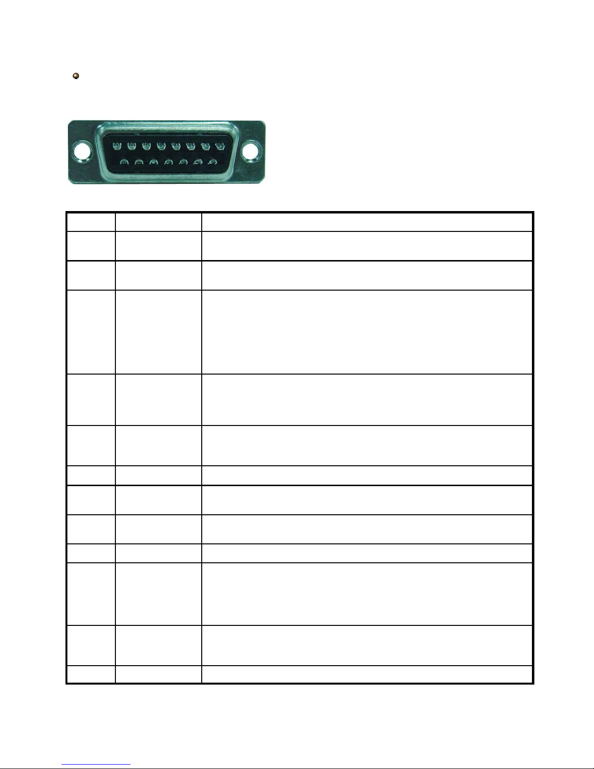
12
Under the normal operation, COM disconnects with NO. But when any alarm is
triggered, COM connects with NO.
Attention: The voltage restriction is under AV/DC 30V.
EXTERNAL
ALARM COM
15
Earth GNDGND16~17
Connecting the wire from ALARM RESET (PIN 14) to GND (PIN 9) connector
will disable alarms. An external signal to ALARM RESET (PIN 14) can be used
to reset both ALARM OUTPUT signal and DVR’s internal buzzer. When any
alarm has been triggered, the signal becomes “Low”, and all alarm activities will
be stopped. Under the normal operation, the signal remains “High”.
ALARM RESET14
PIN OFF12~13
DVR can be controlled remotely by the keyboard of PC by using RS-485 serial
communication signals.
RS485-A11
DVR can be controlled remotely by the keyboard of PC by using RS-485 serial
communication signals.
RS485-B10
Signal GND.GND9
Under the normal operation, COM disconnects with NO. But when any alarm is
triggered, COM connects with NO.
Attention: The voltage restriction is under AV/DC 30V.
EXTERNAL
ALARM NO.
8
Under the normal operation, COM connects with NC and disconnects from NO.
But when any alarm is triggered, COM disconnects with NC and connects with
NO.
Attention: The voltage restriction is under AV/DC 30V.
EXTERNAL
ALARM NC
7
To connect the wire from ALARM INPUT ( PIN 3 -- 6 ) to GND ( PIN 9 )
connector, DVR will start recording and the buzzer will be on.
When “MENU -> CAMERA -> ALARM” is set to “Low” : When the alarm input
signal is “ Low ”, the unit starts to record and buzzer.
When “MENU -> CAMERA -> ALARM” is set to “High” : When the alarm input
signal is “ High ”, the unit starts to record and buzzer.
ALARM INPUT3~6
DVR can be controlled remotely by the keyboard of PC by using RS-232 serial
communication signals.
RS232-RX2
DVR can be controlled remotely by the keyboard of PC by using RS-232 serial
communication signals.
RS232-TX1
DESCRIPTIONFUNCTIONPIN
4CH / 4CH (D)
Solder Side of DSUB 15 PIN
8 7 6 5 4 3 2 1
15 14 13 12 11 10 9
16 17
 Loading...