

Page 1

Volume
1
DVQ4CD-3 DMR8CD-3
DMR16CD-3
User Guide
Page 2

SUPER/CIRCUITS
DVQ-4CD-3, DMR8-CD3, DMR16CD3/ USER
MANUAL
© SUPER/CIRCUITS
11000 NORTH MOPAC EXPRESSWAY
SUITE 300
Austin, TX 78759
Phone 800-335-9777 • Fax 866-2567-9777
Please read instructions thoroughly before operation and retain it for future referenc e
The product specifications and information may be updated without notification.
Page 3
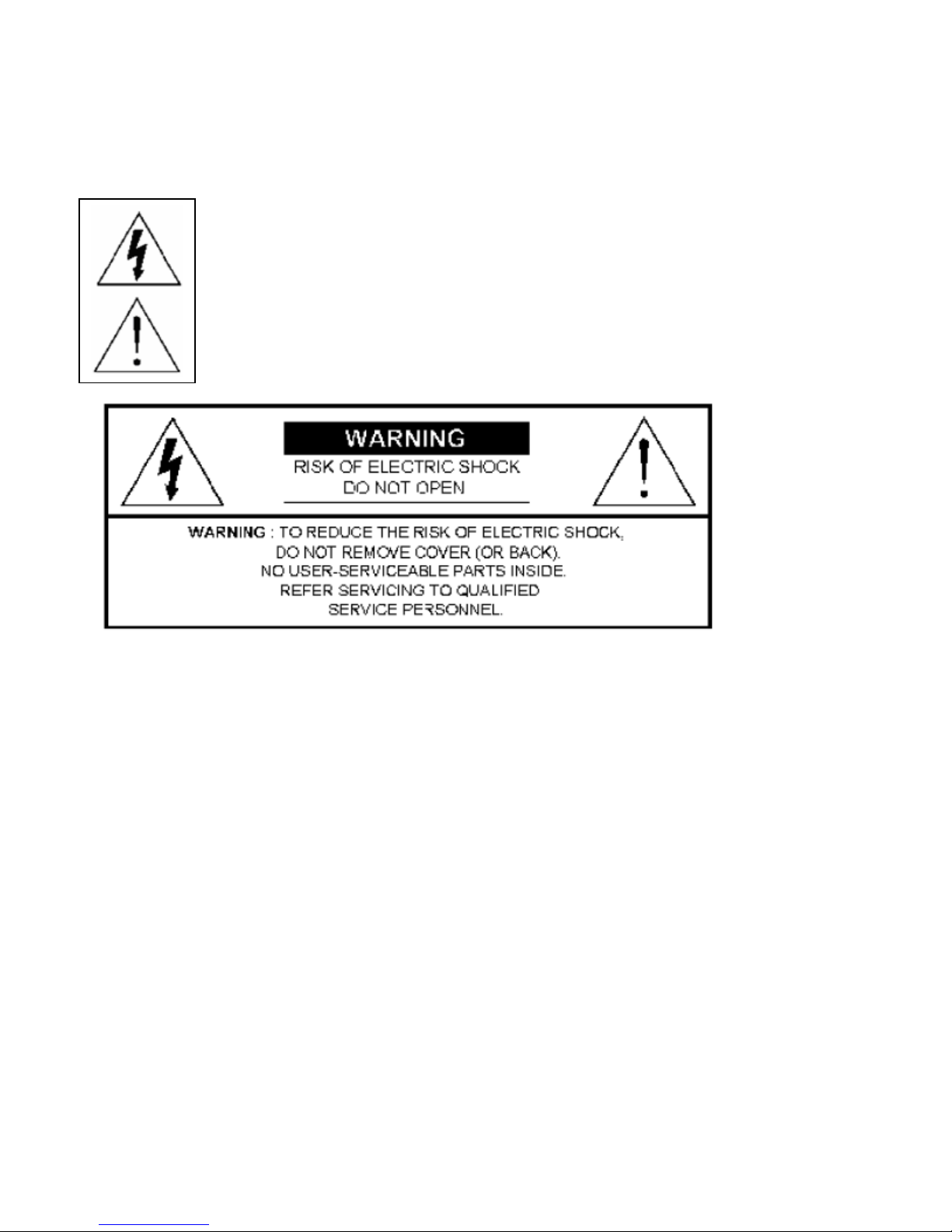
RISK OF EL ECTRIC SHOCK. WARNING: TO REDUCE THE RISK OF ELECTRIC SHOCK, DO NOT
REMOVE COVER (OR BACK). NON SERVICEABLE PARTS INSIDE PLEASE REFER SERVICING TO
QUALIFIED SERVICE PERSONNEL
All the safety and operating instructions should be read before operation. Improper
operation may cause permanent damage.
The lightning flash with arrowhead symbol, within an equilateral triangle, is intended to alert the user to
the presence of uninsulated "dangerous voltage" within the product's enclosure that ma y be of sufficient
magnitude to constitute a risk of electric shock to persons.
The exclamation point within an equilateral triangle is intended to alert the user to the presence of
important operating and maintenance-(servicing) instructions in the literature accompanying the
appliance.
• Use provided adapter.
• Handle equipment with care.
• Do not expose this equipment to open sunlight.
• Do not spill liquid on equipment. Do not use this equipment near water.
• Please power down the unit before unplugging.
• Do not Power on & off quickly (Give unit 15 to 30 seconds when powering off & on).
• Service and Installation should be made by a qualified service technician.
• For your safety, unplug the power before moving, installing, or replacing components.
• Make sure all the power cable and wires are properly installed before operating.
• Avoid dramatic temperature changes, dust, and humidity.
• Operating temperature ranges are from 5C~40C. (41 to 104 degree Fahrenheit.)
• Keep this unit in a well-ventilated place and away from any heat-generating objects.
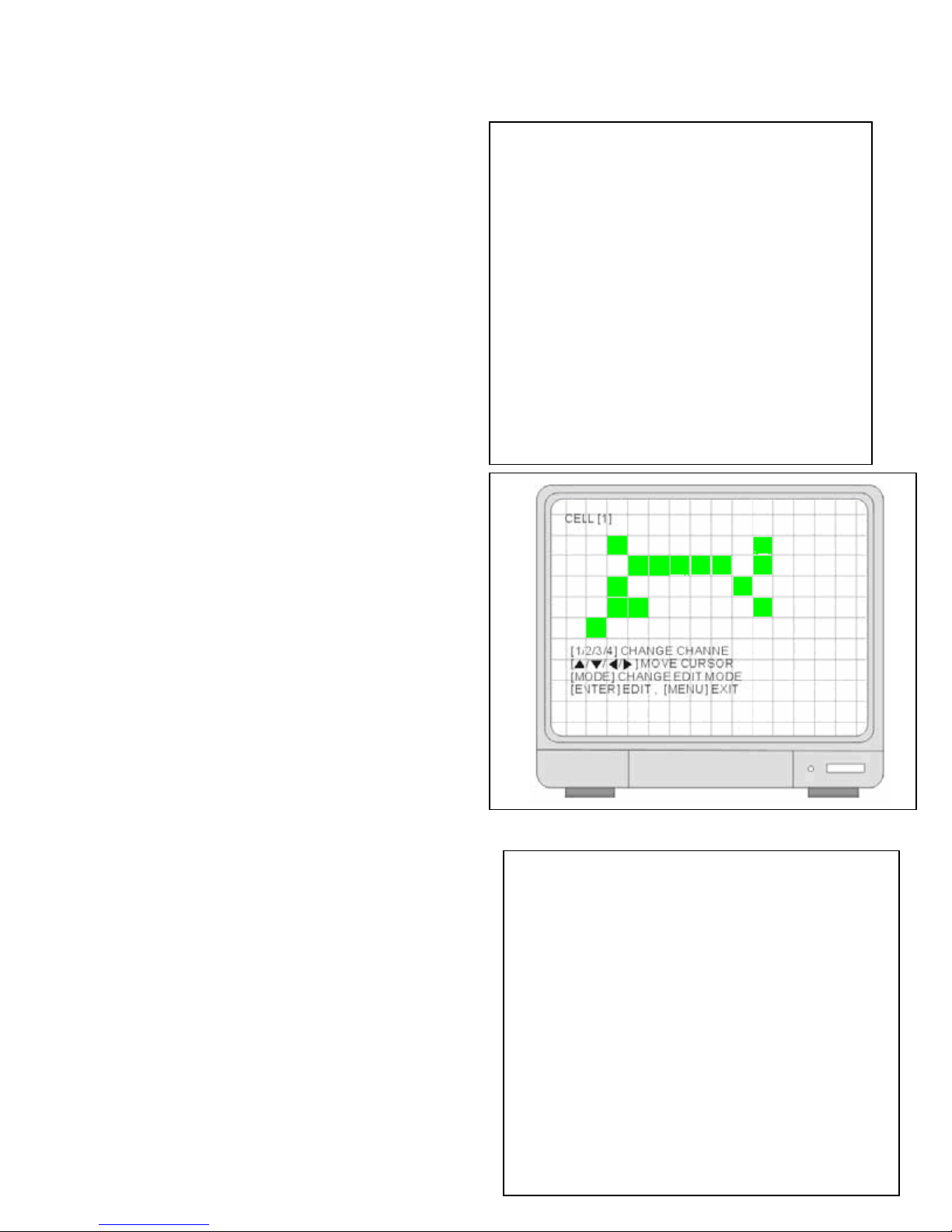
• Do not block the fan and vent areas.
Page 4

Table of Contents
Date: 2007/12/02 VER: 1
PRODUCT OVERVIEW………………………………………………………….…...6
Features…………………………………………………………………………………………….……. 6
Package Includes…………………………………………………………………………………….…..6
Front & Rear Panel Description
• Front Panel Introduction……………………………………………………………………..…8
• Rear panel Introduction………………………………………………………………….…....11
Getting Started………………………………………………………………….…...14
Installation Guide……………………………………………………………………………….……….14
• DVR and Camera Installation……………………………………………………….…….…16
• DVR and Monitor Installation……………………………………………………….………..17
Basic Menu Setup………………………………………………………………...…18
Getting Started with Basic Menu Setup………………………………………………………….…...18
• System Menu……………………………………………………………………………….…20
• Factory Default………………………………………………………………………….…….20
• Clear HDD……………………………………………………………………………….…….21
• Time/ Date Setup………………………………………………………………………… .….23
• Record In Motion………………………………………………………………………….…..24
Advance Menu Setup……………………………………………………………....31
System Menu…………………………………………………………………………………………....31
• Display Setup……………………………………………………………………………….….32
• Monitor Setup………………………………………………………………………………..…34
• Configuration…………………………………………………………………………………...35
• HDD Management……………………………………………………………………………..36
o Time/ Date Setup………………………………………………………………….…37
o Camera Setup…………………………………………………………………….….38
• Motion Setup…………………………………………………………….….40
• Interval Setup……………………………………………………………....46
o Alarm Setup……………………………………………………………………….….47
o Event Popup Setup……………………………………………………………….…47
o Buzzer Setup………………………………………………………………………...48
o Password Setup……………………………………………………………..…...….48
o System Information……………………………………………………………….…49
• Record Setup……………………………………………………………………………....….50
o Record Configuration………………………………………………………………..50
• Overwrite………………………………………………………….……..….50
• Multiplex…………………………………………………………….………50
• Quality……………………………………………………………………….51
• Resolution………………………………………………………………..…51
…………..………………………………………………………...….8
4
Page 5

• Record in Alarm………………………………………………………….....51
• Record in Motion……………………………………………………..….….51
• Continuous Record……………………………………………………...….51
• Schedule Setup……………………………………………………………………………..…52
• Holiday Setup……………………………………………………….…………..…….….……54
• CD Backup………………………………………………………………………….…….....…54
o CD/ DVD Backup………………………………………………………………….…55
o CD/ DVD Backup Player Software Installation…………………………………...56
• External Devices……………………………………………………………………….….…..60
o TCP/IP Setup…………………………………………………………………..…….60
o RS232C Setup……………………………………………………………………….62
o PANTILT Setup………………………………………………………………………63
o SPOT Setup……………………………………………………………………..…..64
o AUDIO…………………………………………………………………………….….65
• Factory Default……………………………………………………………………………..…66
• LANGUAGE ……………………………………………………………………………….…..67
Advance Hardware Installations
SPOT………………………………………………………………………………………………....68
LOOP……………………………………………………………………………………………..….69
Sensor and Alarm Installation…………………………………………………………………..…70
Serial Port Setup……………………………………………………………………………….…...71
PTZ Camera Installation and Operations……………………………………………………...…73
Microphone and Speaker Installation………………………………………………………….…75
HDD Installation……………………………………………………………………………….……76
………………………………………………………..…...68
Operation…………………………………………………………………………..…77
Display Configuration……………………………………………………………..………….……77
Screen Switch……………………………………………………………………………….….….79
PIP View……………………………………………………………………………………….……79
Freeze View………………………………………………………………………… ………….…..79
View in Sequence………………………………………………………………………………….80
Zoom View………………………………………………………………………………………….80
Key Lock………………………………………………………………………………………….…81
Switch Audio Channel……………………………………………………………… ………….….81
Record………………………………………………………………………………………………82
Playback………………………………………………………………………………………….…83
Search Mode……………………………………………………………………………………….84
Network and Client Software………………………………………………….….88
Network Introduction………………………………………………………………………………88
• Network Installation and Setup…………………………………………………………88
Installing Network Software……………………………………………………………………….94
Dynamic IP Settings…………………………………………………………………………...…101
Remote Live View VIA IE Browser…………………………………………………………..…107
Web Network Backup…………………………………………………………………………....109
Specifications………………………………………………………………………114
Appendix 1 Record Time Table……………………………………….……..….116
Appendix 2 System Configuration………………………………………..……118
Appendix 3 Play Only Mode………………………………………………..……118
5
Page 6

Chapter
1
Product Overview
1. Features
DVQ 4 records 120 frames per second max using lowest resolution.
DMR8/16 records 480 frames per second max using lowest resolution.
Remote viewable via 10/100 Ethernet
Easily backup hard drive data to DVR-R burner
Selectable motion detection recording
Instant search by time, alarm events, etc.
2 internal hard drive bays
Password protection
Jog/Shuttle dial allows frame by frame review
On-screen setup menu, title, and system timer.
Time/Date stamp
Time lapse and real-time recording.
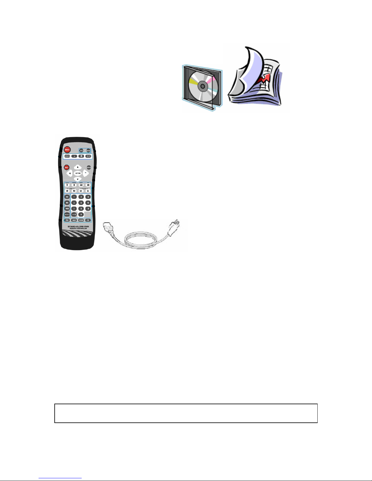
2. Package Includes
• DVQ or DMR unit × 1
• Power Supply × 1
• Power Cable × 1
• Remote Controller × 1
• Manual × 1
• Software CD-R × 1
• Accessories × 1
• Battery × 2
6
Page 7
Ca t
DVR-1 CD Manual
REMOTE Power cord Power Supply
Package
NOTE: Check the package to make sure that you receive all accessories which include the
components shown above.
7
Page 8
Front & Rear Panel Description
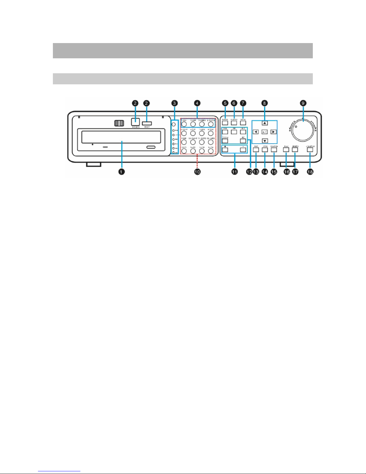
Front Panel Introduction
**Special NOTE for line items 6 and 19**
1. DVD+R burner
• Built-in DVD+R burner.
2. USB Port
• Used to connect PC to DVR for firmware upgrade.
• USB memory stick backup.
3. IR Receiver & LED Lamps
• IR Remote Controller Receiver.
• DVR Status LED.
o RUN- Flashes when picture by picture play through J. Shuttle.
o ACTIVE- On when the J. Shuttle is ready for use.
o REC- On while recording and flashes at stand-by mode.
o PLAY- On while playback.
o FULL- On when HDD storage is full.
o NET- On when the DVR is connected remotely.
4. 1~16 Channel Button
• Select channel for full screen display.
5. MODE
• Switch to full or split screen display.
6. **K.LOCK**
• Security lock out to help prevent unwanted DVR access. DO NOT PUSH THIS BUTTON
unless you know what your password is. Default password is blank (_______), press the
“ENTER key” to confirm password. See your “PASSWORD SETUP” to change your
password.
7. MENU
• Enter the menu set up.
8
Page 9

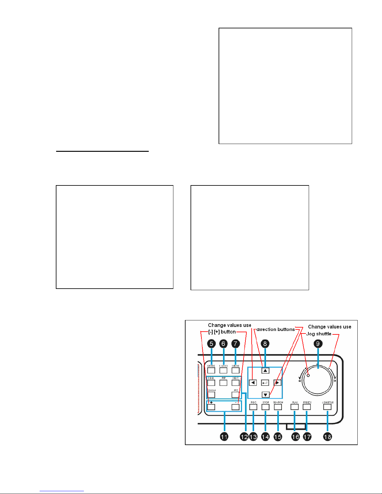
8. Arrow Keys & ENTER
• Directions- Navigate the menu.
• ENTER- Confirm the selected options.
9. Jog Shuttle
• Use inner Jog shuttle control for frame by frame image display. Turn clockwise for
forward and turn counter-clockwise for reverse.
• Use outer Jog shuttle control for fast forward and fast reverse.
P.1 Appear
10. PTZ
• Press the PTZ buttons to control the PTZ camera directly.
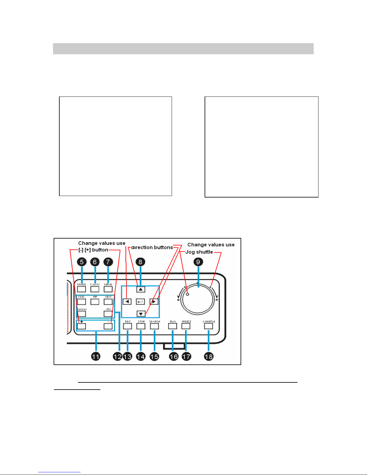
11. [ + / - ]
• Adjust set-up value.
• Control screen display channel.
12. Control
• SEQ/AUDIO - Press for AUDIO. Press and hold for 3 seconds to enter SEQ mode.
• SEQ -Full screen sequencing/ PIP screen sequencing.
• AUDIO - Press to play the audio, and press again to switch audio channels.
• PIP – Press PIP to enter the Picture in Picture mode.
• NEXT –
o Go to the next PTZ command in PTZ mode.
o Switch from full screen display to split screen display.
• ZOOM - Press ZOOM key to enlarge specific picture area.
13. REC
• Press to activate continuous record. Record settings used for recording are Super fine
quality and Best resolution.
14. STOP
• Stop record.
• Stop playback and return to the live mode.
15. SEARCH
• Enter search options. (Percentage, date / time, or the event list).
16. PLAY
• Play recorded video.
17. FREEZE
• Freeze in full screen or split screen
18. J.SHUTTLE Button
• Activate the Jog Shuttle and press again to deactivate
19. **ENTER KEY**. Enter your selections for MENU entries.
9
Page 10

10
Page 11
BACK PANEL INTRODUCTION
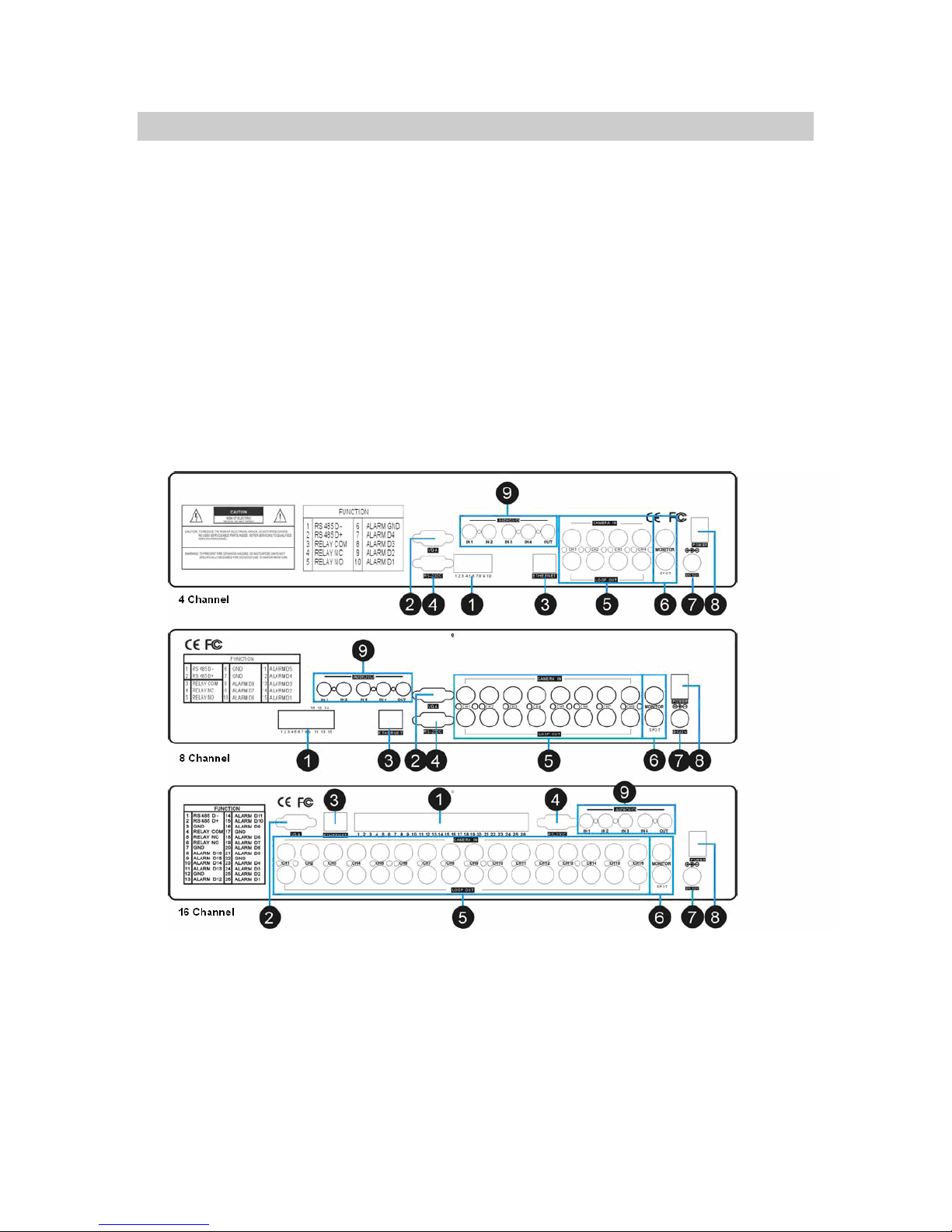
1. RS485, Relay Output, Sensor Input
• RS485, for connection to PTZ cameras.
• 16 sensor inputs and 1 relay output.
2. VGA Output
• Connection to a VGA monitor or TFT LCD.
11
Page 12

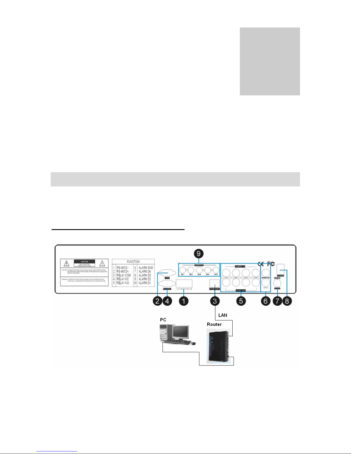
3. ETHERNET
• LAN connection.
4. RS-232C
• Use to connect to PC or other serial control devices.
5. 1~16 Camera Input/ LOOP Output
• CAMERA IN- channels 1~16 camera input.
• LOOP- channels 1~16 camera video out.
6. Monitor / SPOT Output
• MONITOR - Connection to main monitor.
• SPOT- Alarm or motion triggered monitor output display.
7. Power Input
• DC power input (DC12V)
8. Power Switch
• Power ON/OFF
9. Audio Input/Output
• 1 ~ 4 Audio input channels/ 1 Audio output channel.
IR remote controller introduction
1. MENU
• Enter menu or exit
2. Split /OSD
• 4S: 4 split screen
• 9S: 9 split screen
• 16S: 16 split screen
• AUDIO: Press to play the audio, press again to
go to the next audio channel.
3. 1~16 Channel
• Switch channel in live or playback.
4. Control function
• FRZ - Freeze screen display
• SEQ - Display screen sequence
• ZOOM - Press ZOOM key to enlarge specific
picture area. Use the direction buttons to guide
ZOOM target.
• PIP- Picture in Picture. Enter PIP mode in full
screen
5. Mode/PT
• MODE- Multi-screen display
• P/T- Enter the PTZ camera control mode
12
Page 13

6. SEARCH/-/+/NEXT
• SEARCH - Open the search window in playback
• [-]/[+] – Adjust options in set-up
• NEXT- Go to the next PTZ command in PTZ mode. / Go to the next channel in full screen
display/ Go to next page in split screen display.
7. Rec
• Continuous Record.
8. Stop
• Stop the record and return to previous record setting.
• Stop playback and return to the LIVE mode.
9. Functions
• PLAY - Play recorded video.
• PAUSE - Pause playback.
• REW - Fast rewind, press again to adjust speed.
• FF - Fast forward, press again to adjust speed.
• STEP - Play frame by frame.
• SLOW - Slow motion playback, press again to adjust speed.
10. ENTER
• Select option.
11. Direction
• Navigate the menu.
13
Page 14

Chapter
2
GETTING ST ARTED
Installation Guide
Camera and Monitor Installation
This manual has been carefully written to help you assemble and configure your digital video
recorder system for optimal performance. It’s easy to setup your digital video recorder just follow
the instructions on pages 14 through 30 for your basic setup. If you have any comments
questions about this manual, please feel free to call us at 800-335-9777.
1. Remove your monitor from the box for testing your cameras and cables. You can use a TV
set with a video input if you don’t have a monitor. Plug your monitor into a 110-120 AC power
source. Do not mistake the antenna input on the TV for a VIDEO INPUT. Monitors and TV’s
have video inputs clearly marked. The TV RCA input will look some what like the image
below (labeled VIDEO INPUT). This type of input connector is called an RCA female input
jack.
2. Remove your cameras and camera power supplies from the box. Make sure you’re using
power supplies that have a REGULATED POWER SUPPLY 12 VOLT OUTPUT (very
important). Most power supplies have a label on the back that will tell you the type of output
the power supply is capable of producing. If there is no label, DO NOT USE THE POWER
SUPPLY.
14
Page 15

NOTE: Un-regulated power supplies are very common and will damage your cameras.
3. Connect each one of your cameras to your regulated power supply and cable assembly.
Most cable assemblies are 100 ft long or more. You will see all types of cable configurations
here is one example of a cable option below.
4. Test each component of your video system prior to installation. Connect each camera
directly to the video monitor, using a new power adapter and cable for each camera. This will
test each component of your video system and confirm proper function prior to installation.
15
Page 16
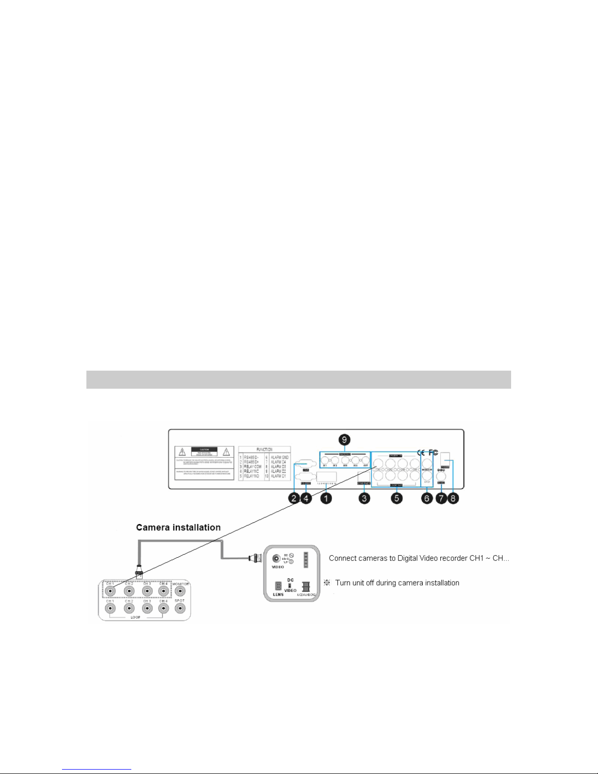
5. Connect the digital video recorder to cameras.
DVR and Camera Installation
16
Page 17
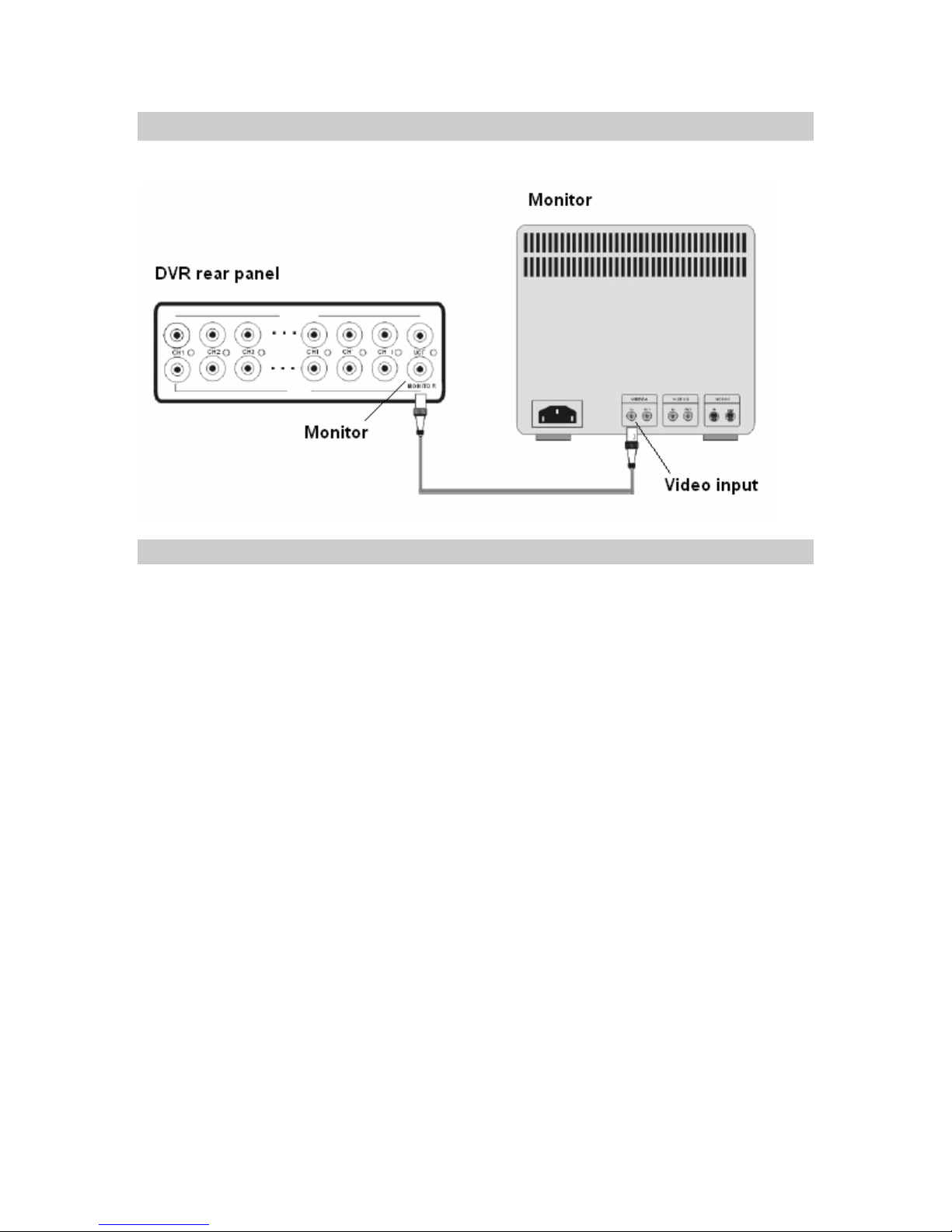
DVR and Monitor Installation
DVR system diagram
17
Page 18

Chapter
3
BASIC MENU SETUP
GETTING STARTED with the BASIC MENU
SETUP
In this section we will cover basic menu settings to get you started and operational right away.
Connect the AC Power Cord with Power Adapter and plug into an electrical AC outlet. Power
switch is on the rear panel, turn the switch on. It will take approximately 5 to 15 seconds for the
system to completely finish initializing.
Caution: Only use 100~240VAC 50~60HZ / 12VDC 8A or 5A power supply.
18
Page 19
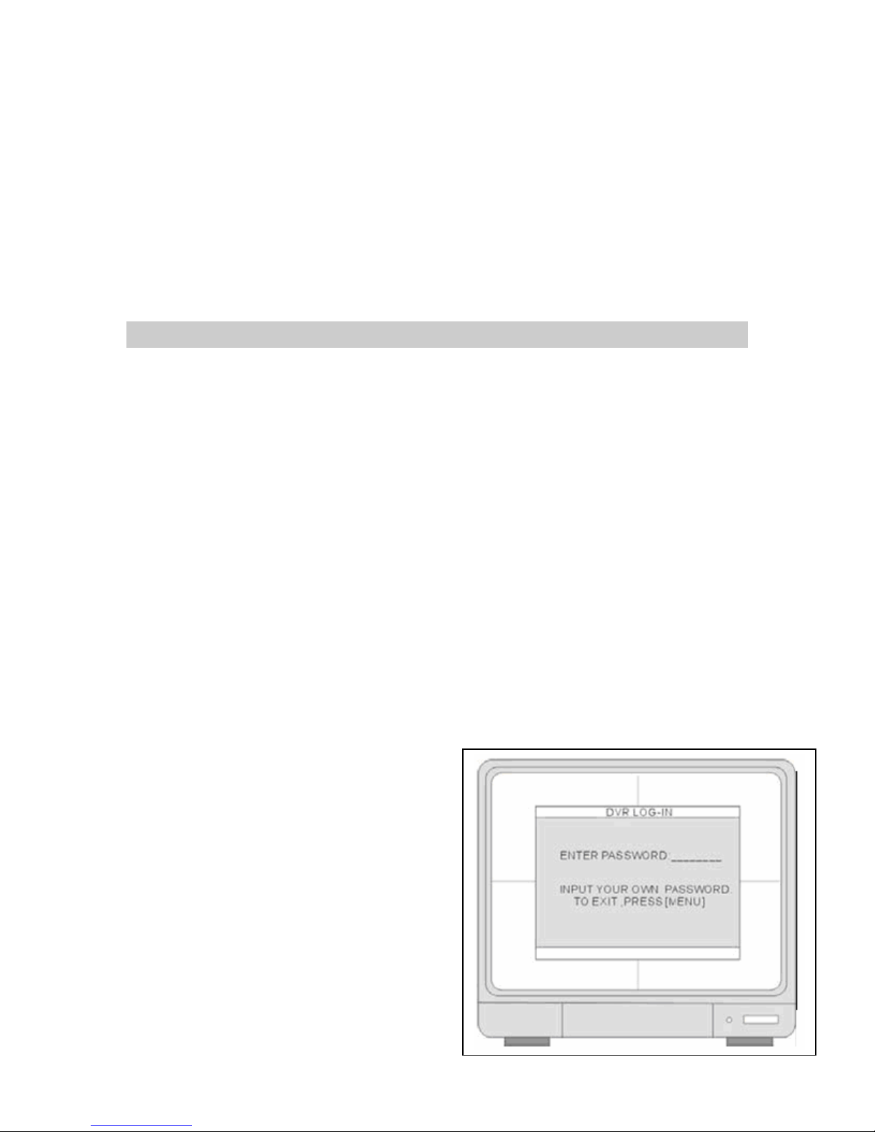
Before operating the digital video recorder you will need to set up the SYSTEM MENU within the
DVR.
Go into the MENU and run the FACTORY DEFAULT, CLEAR HARD DRIVE and change the
SYSTEM TIME.
1. FACTORY DEFAULT
2. CLEAR HARD DRIVE
3. SYSTEM TIME
BASIC MENU SETUP
1. Press the MENU key on the front panel to login.
2. Use CH. SELECTORS 1 ~ 16 to key in the password.
3. Press ENTER to confirm and you will enter the
Menu system.
NOTE: You don’t have a password in the
system, if this is your first install. Your
password is blank or “(___________) “, do not
enter a password at this time, and hit the >
ENTER key.
19
Page 20
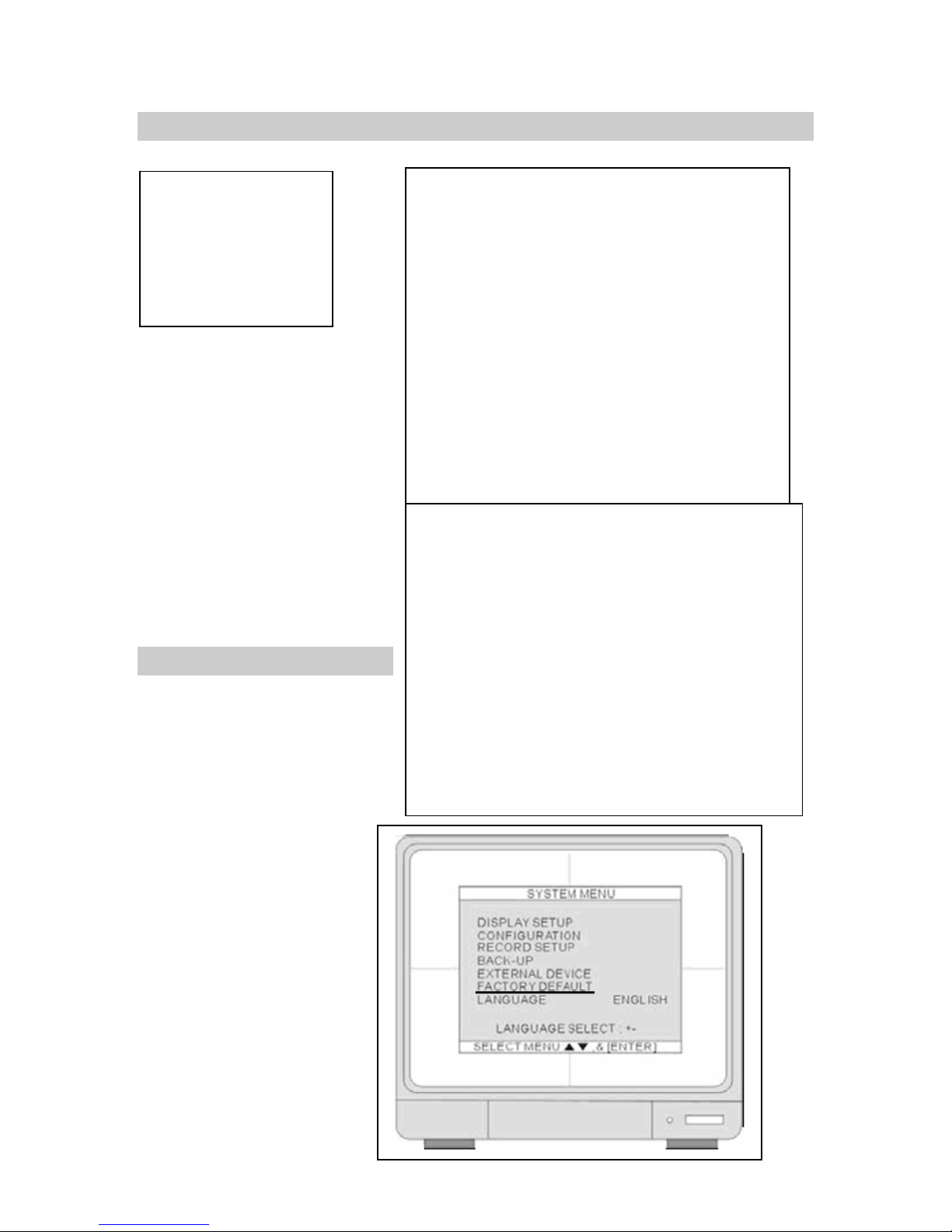
SYSTEM MENU
1. DISPLAY SETUP
2. CONFIGURATION
3. RECORD SETUP
4. BACK-UP
5. EXTERNAL DEVICE
6. FACTORY DEFAULT
7. LANGUAGE
.4 Set
CH
AP
Up
FACTORY DEFAULT
4. Press UP and DOWN
arrow keys and hit the
ENTER key for selection.
Move the cursor to
FACTORY DEFAULT and
hit the ENTER key.
20
Page 21
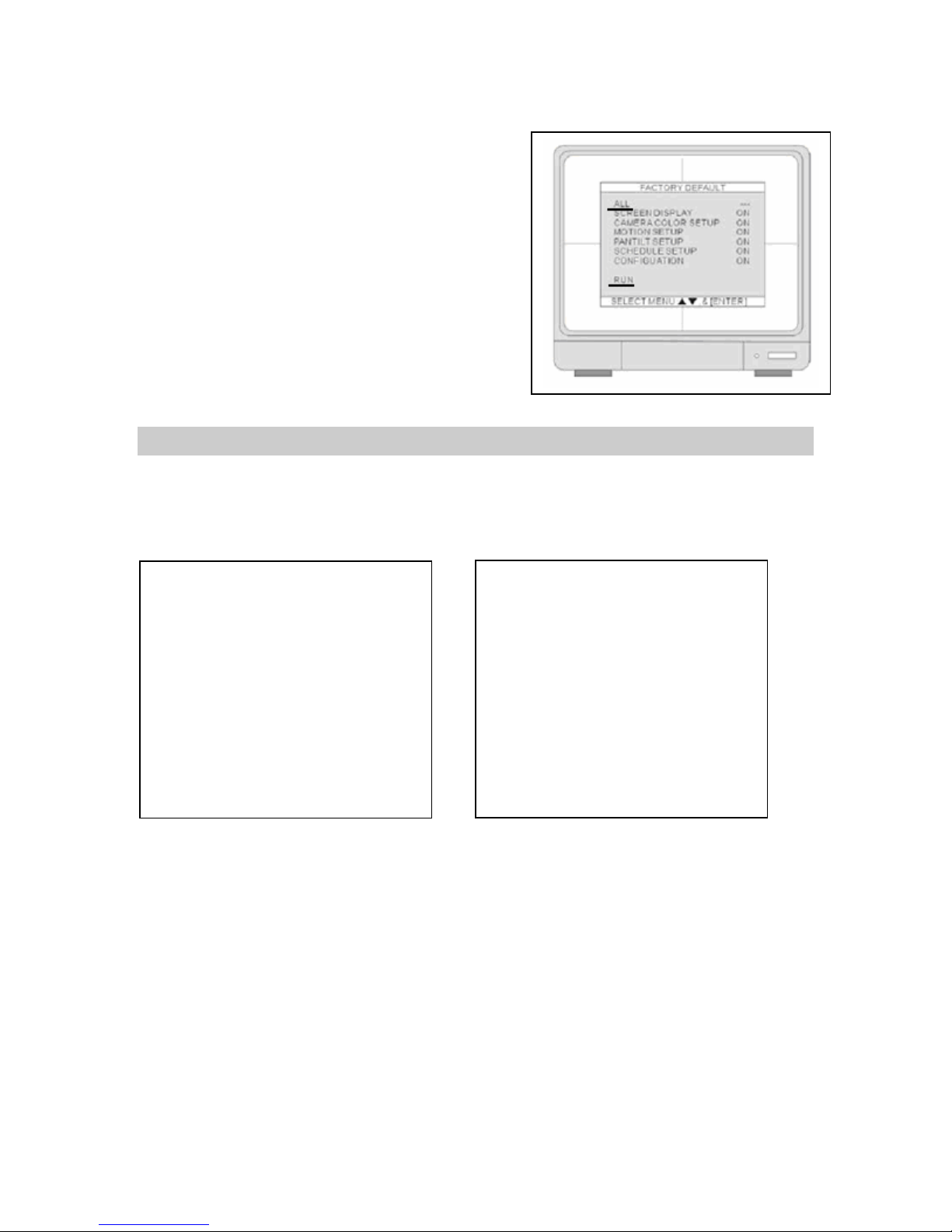
5. Move the cursor to ALL and hit the ENTER key to
turn all FACTORY Defaults ON. Move the cursor
to RUN and press the ENTER key to execute the
Factory Default. All options will turn to OFF.
6. Hit MENU Key to exit.
7. Let’s CLEAR the HDD.
CLEAR HDD
In the SYSTEM MENU select CONFIGURATION and hit the ENTER key. Go to HDD
MANAGEMENT and hit the ENTER key.
21
Page 22
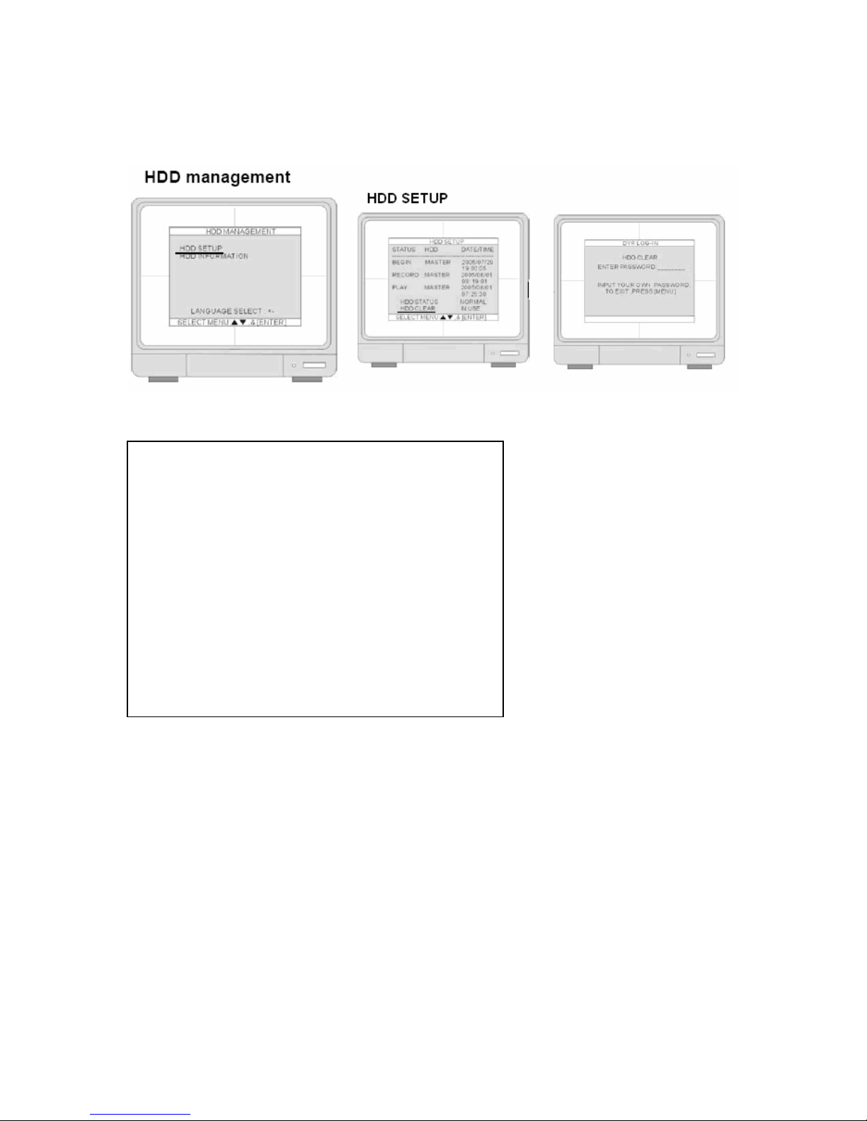
8. Select HDD SETUP hit the ENTER key, move the cursor to HDD CLEAR and hit the ENTER
key. Enter a password, which at this time is blank (_________), just hit the ENTER key
again. HHD CLEAR will show EMPTY.
9. Hit the MENU Key twice to exit to CONFIGURATION MENU.
10. Go to TIME/ DATE SETUP.
22
Page 23
TIME/ DATE SETUP
11. From the main SYSTEM MENU select CONFIGURATION, go to TIME/DATE SETUP hit
the ENTER key.
12. The date and time set by the manufacturer maybe different from your time zone. It is very
important to set up the system date and time before the DVR starts recording. Set the date
and time by using direction buttons and [-] [+] button or Jog shuttle.
NOTE:
playback errors.
DO NOT change the date and time after the recording starts it may and cause
23
Page 24
• Date format- Asia/American/European
Time format- 12 hours/24 hours
Month format- English/Numeric
13. Use American, 12 hours/24 hours is
optional, use English.
14. Move on to MOTION SETUP. Exit
TIME/DATE SETUP and go to SYSTEM
MENU.
RECORD IN MOTION
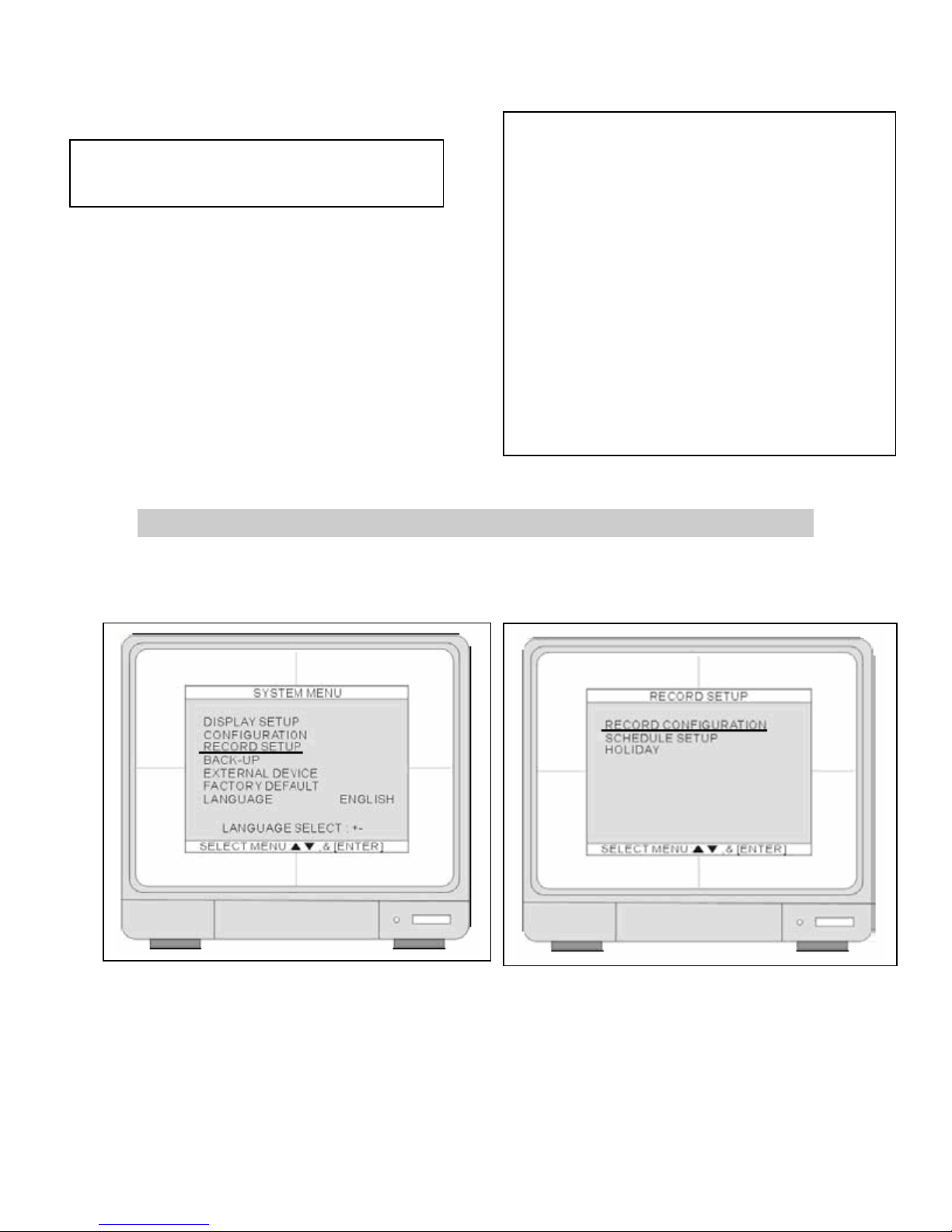
15. Under SYSTEM MENU select REORD SETUP and hit the ENTER key. Select RECORD
CONFIGURATION.
24
Page 25
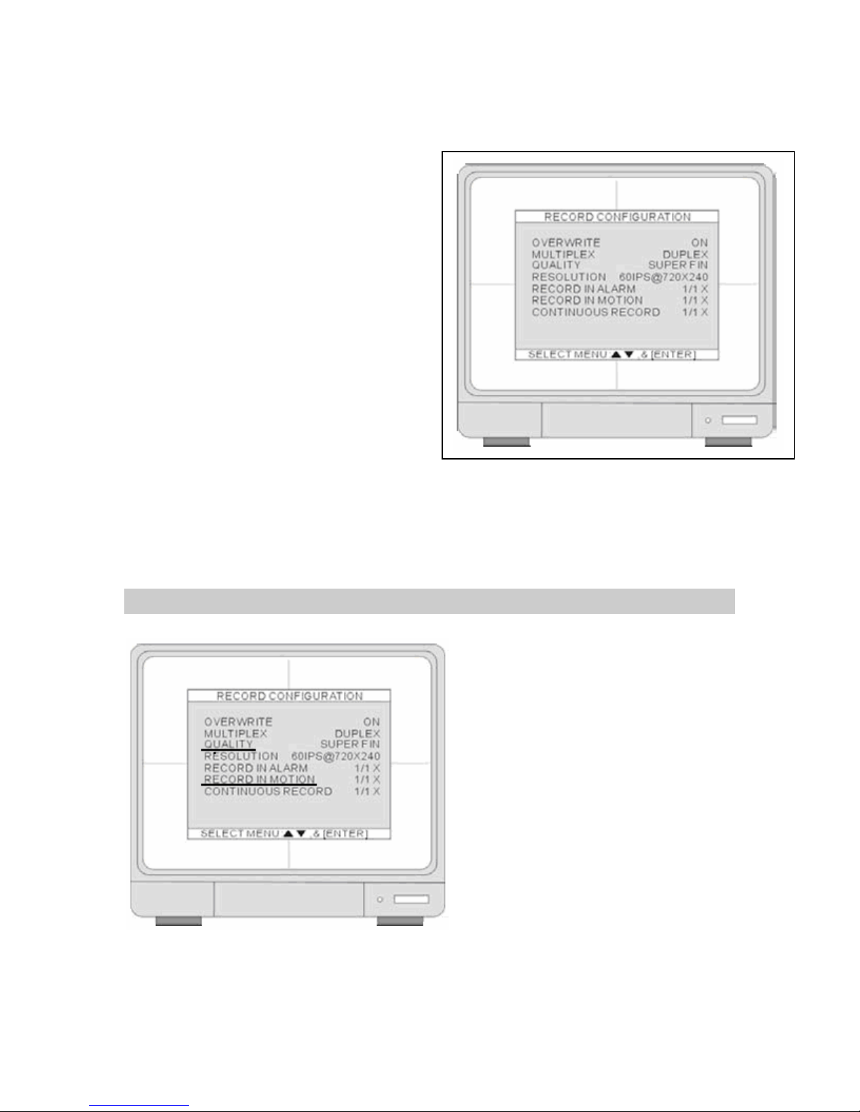
Use the UP and DOWN arrow keys to select an item. Use the [+] and [-] keys to change the
value.
16. Set OVERWRITE to ON. When the hard
drive is full, the system will overwrite the
earliest recorded data. If the DVR has two
hard drives, the overwriting starts from
the Master drive. For this exercise,
leave OVERWRITE in the ON position.
17. Set MUTIPLEX to DUPLEX, this will allow
record and remote connection
simultaneously. The DVR stops recording
while the DVR enters playback. Leave in
DUPLEX mode.
18. Move on to QUALITY and RECORD IN MOTION.
QUALITY & RECORD IN MOTION
Review the charts below they will help you decide what options to go with for QUALITY and
RECORD IN MOTION settings.
25
Page 26
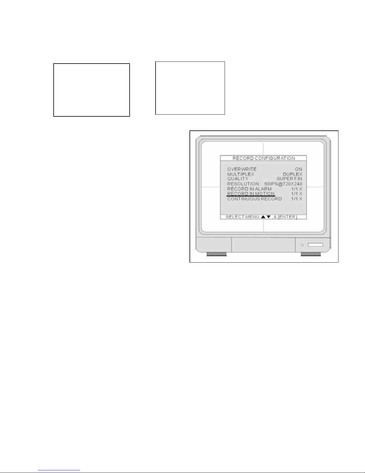
The QUALITY mode has 5 options. Option names can be different depending on DVR version.
4, 8, 16 CHANNEL DMR.
1. HYPER
2. SUPER
3. HIGH
4. MID
5. LOW
The RECORD IN MOTION mode has different
parameters to choose from 1/1, 1/2, 1/3, 1/4… to
1/999. The higher the denominator the longer
period you can record. The recording speed is
expressed in fractions. The 1/ 1 record setting
will record at full recording speed. The 1 / 2
record setting will record at half of the recording
speed. The 1 /3 record setting will record at one
third of the recording speed.
QUALITY features provide different levels of
quality depending on your application.
Sometimes we are willing to give up on video
quality to get more hours out of our digital video
recorder. IPS is IMAGES PER SECOND or the
number of pictures your digital video recorder will
take in 1 second. A good example of IPS is to
imagine taking 30 pictures with a digital camera
of some one walking across a room. If you laid
out the 30 pictures, what you will have is a
smooth flowing sequence of pictures of someone crossing a room. If you take out every other
picture, you have 12 pictures and you would have a snap shot picture affect. A 12 picture
sequence or 12 images a second is not considered real time video. 30 to 15 image s per second
is considered real time and 12 to 1 images a second will reduce the real time affect.
Here is an example to further explain the charts below; for this exercise Lets say we are using a 4
channel DVR and want to record for 7 days. If we look at the chart we have four choices;
1. 8.4 days
2. 7.5 days
3. 7.2 days
4. 9 days
5. 10.8 days
8, 16 CHANNEL DMR.
1. SUPER FINE
2. FINE
3. ENHANCED
4. NORMAL
5. BASIC
26
Page 27
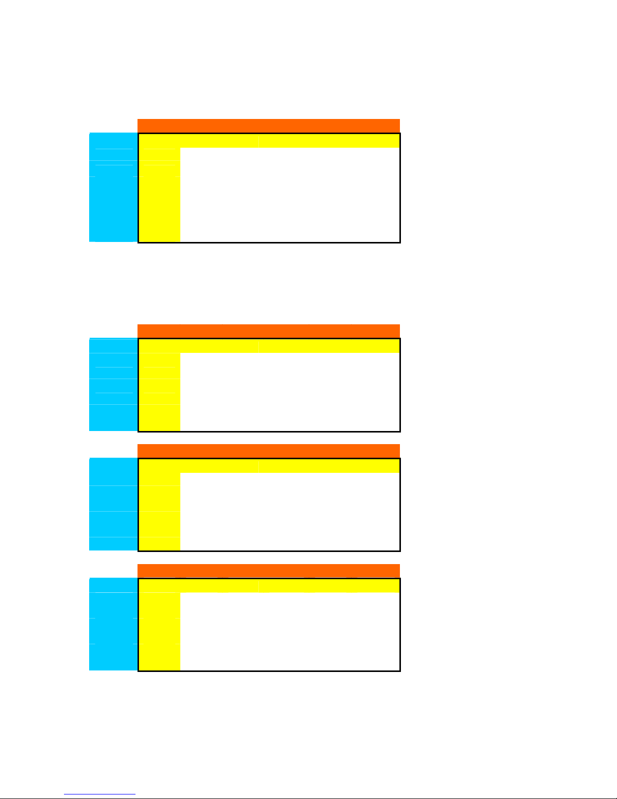
If you like high quality video, then your choice would be 7.2 with a QUALITY at HYPER and an
IPS set at 1/4. If you would like a better flowing video (closer to real time) then your choice would
be 8.4 with QUALITY at LOW and an IPS set at 1/2.
4 Ch
IPS 1/3
This testing was done with a 250G HDD and data is expressed in days. This data is a rough
estimate to get you close to your time target. Do a test run of your QUALITY and RECORD IN
MOTION settings and review your results.
¾ NOTE:“TEST YOUR SETTINGS BEFORE FINAL INSTALL”
4 Ch
IPS 1/3
8 Ch
IPS 1/3
16 Ch
IPS 1/3
IPS Low Mid High Super Hyper
Low Mid High Super Hyper
Low Mid High Super Hyper
Low Mid High Super Hyper
1/1
1/2
1/4
1/5
1/6
1/1
1/2
1/4
1/5
1/6
1/1
1/2
1/4
1/5
1/6
1/1
1/2
1/4
1/5
1/6
8.4
12.6 9.4
16.8 12.6 10.1 8.4
25.2 18.9 15.1 12.6
12.6 9.4 7.5 6.3 5.4
16.8 12.6 10.1 8.4 7.2
25.2 18.9 15.1 12.6 10.8
10.5 7.9 6.3 5.2 4.5
12.6 9.4 7.5 6.3 5.4
QUALITY
4.2 3.1 2.5 2.1 1.8
6.3 5 4.2 3.6
7.5
21 15.8 12.6 10.5
QUALITY
4.2 3.1 2.5 2.1 1.8
8.4 6.3 5 4.2 3.6
21 15.8 12.6 10.5 9
QUALITY
2.1 1.5 1.2 1 0.9
4.2 3.1 2.5 2.1 1.8
6.3 4.7 3.7 3.1 2.7
8.4 6.3 5 4.2 3.6
QUALITY
1 0.75 0.6 0.5 0.45
2.1 1.55 1.25 1 0.9
3.1 2.3 1.87 1.5 1.3
4.2 3.1 2.5 2.1 1.8
5.2 3.9 3.1 2.6 2.2
6.3 4.7 3.7 3.1 2.7
6.3 5.4
7.2
9
10.8
27
Page 28
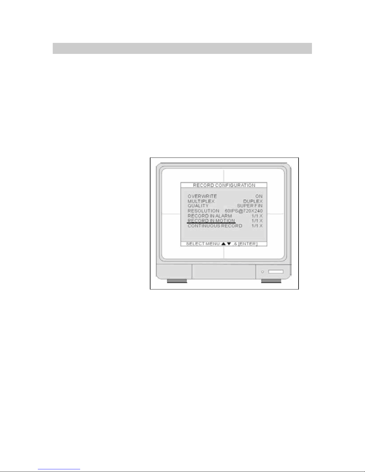
EXTENDING YOUR RECORDING TIME
We can extend the recording time by introducing a larger hard drive or increasing the RECORD
IN MOTION parameters - 1/1, 1/2, 1/3, 1/4… to 1/999. The higher the denominator the longer
period you can record.
NOTE: You are not limited to the tables above; remember increasing the lower number or
denominator will get you 1 day to months of recording time. To start find the nearest date you
would like, for example lets take the 16 channel DVR and I’m looking for 30 days. You would
start by looking at LOW QUALITY and an IPS of 1/6. Take the 6.3 days, divide 30 days by 6.3
and this will give us 4.76. Multiply 4.76 by the denominator 6 and this will give us 28.57, take it to
the nearest whole number. Enter an IPS of 1/29 and LOW QUALITY to get you in the ball park of
30 days. Remember to do a test run.
18. Select how many days you would like and enter the values.
19. Exit by hitting MENU once
and go into SCHEDULE
SETUP.
28
Page 29
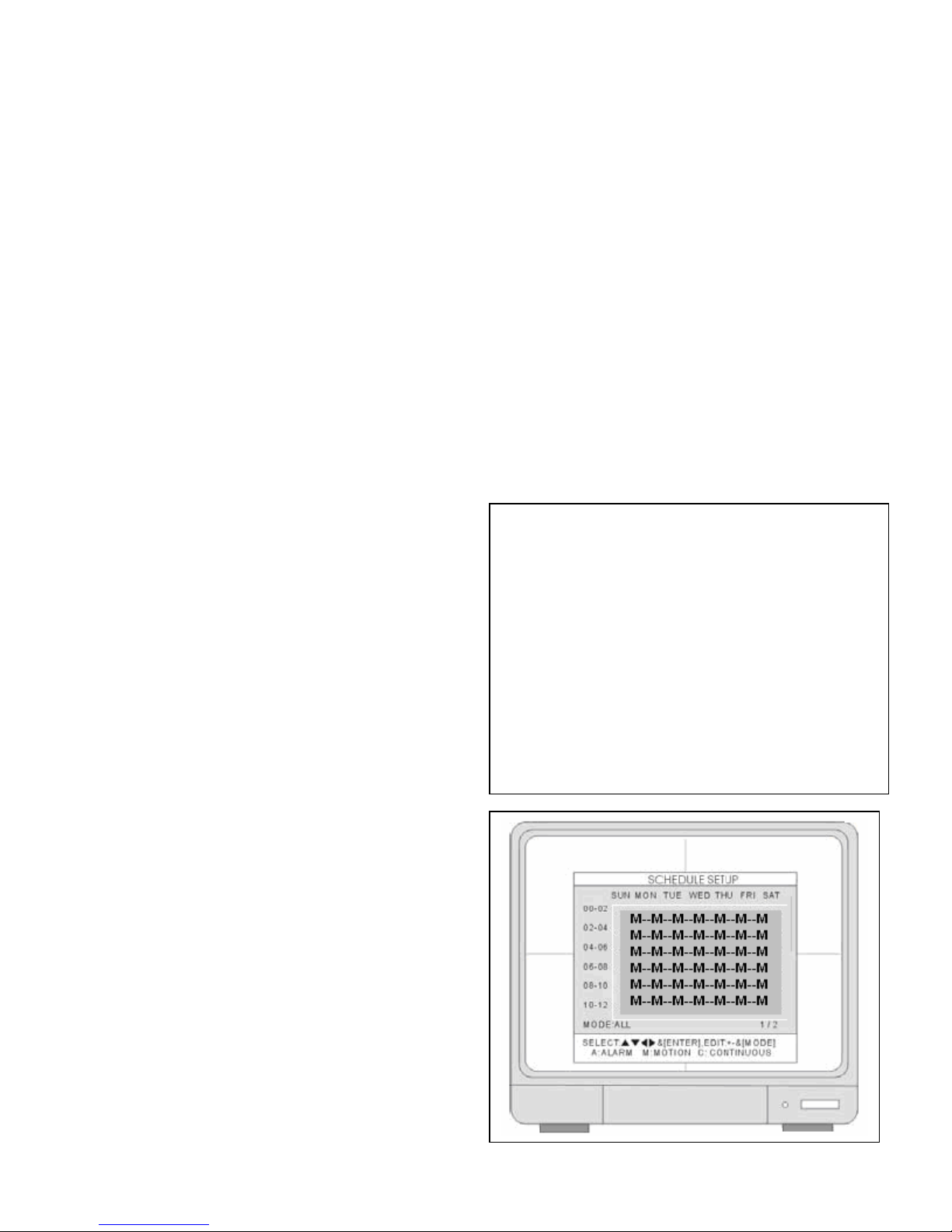
SCHEDULE SETUP
20. Hit the ENTER key.
21. Hit the “–“ minus key.
Your monitor screen should look like this,
showing all M’s indicating motion detection.
22. If not press the MODE key.
29
Page 30
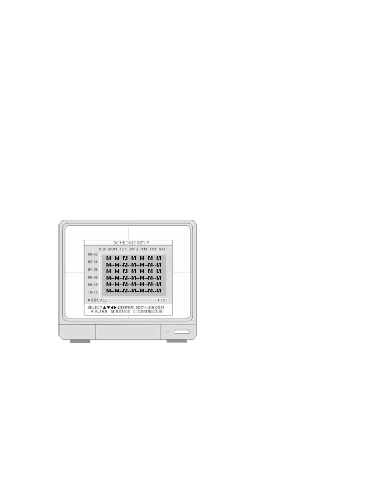
• MODE: Press MODE to select an editing mode. Continue till you see “MODE: ALL” at
bottom of screen, then press [+] and [-] to select a recording mode M.
23. Continue to press MENU to exit all menus at this time. We are done for now and your
system should be up and running. The letter M will display on your monitor indicating you
are recording in motion. Exit MENU and turn the DVR off for about 20 seconds.
THIS CONCLUDES BASIC SETUP AND YOU SHOULD BE OPERATIONAL. PLEASE
CONTIUNE READING THE USER MANUAL FOR FURTHER OPTIMAL CONFIGURATION
SETTINGS. IF YOU HAVE ANY QUESTIONS PLEASE CONTACT OUR TECHNICAL
SUPPORT GROUP AT 800-335-9777.
30
Page 31
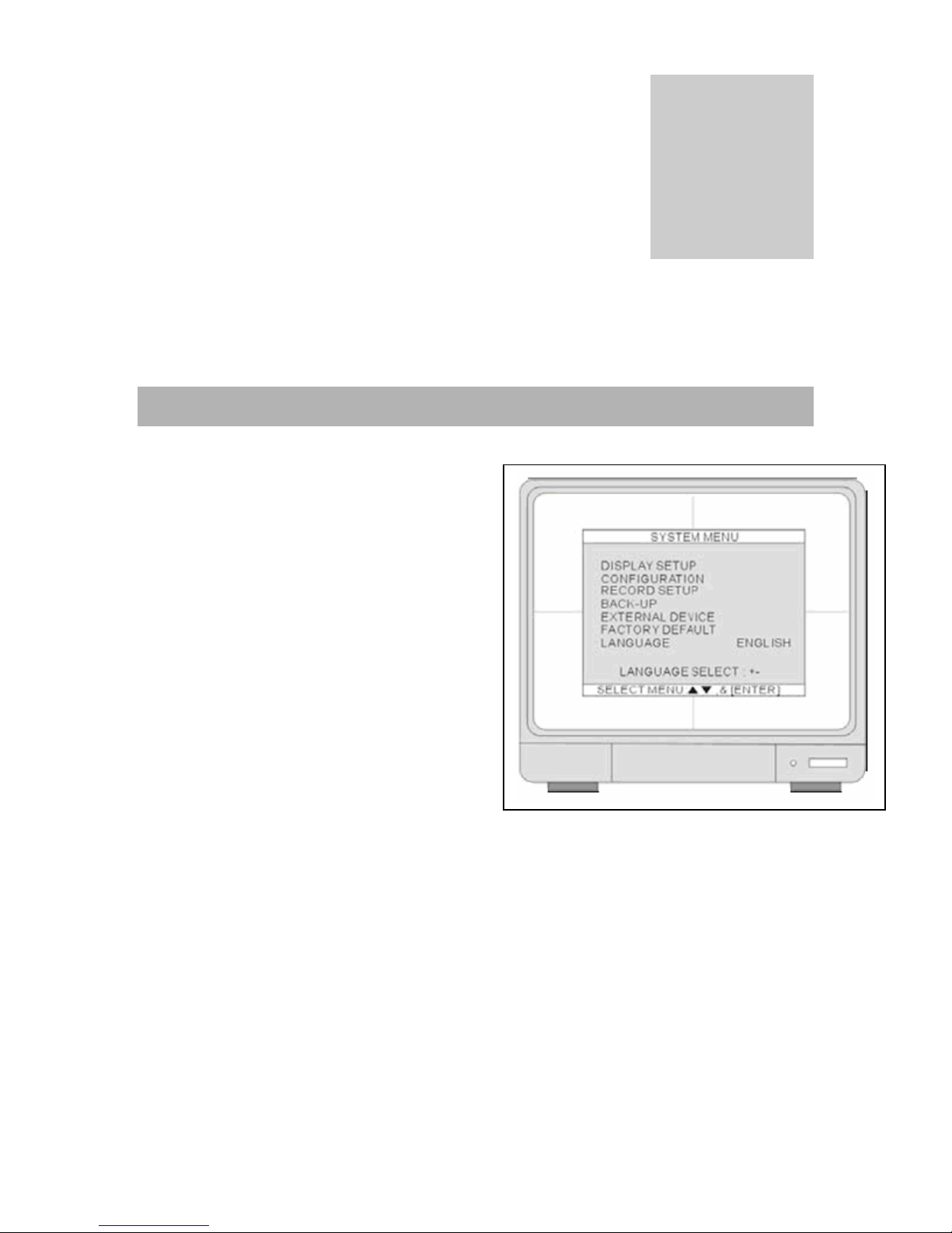
ADV ANCE MENU SETUP
SYSTEM MENU
1. DISPLAY SETUP
• Includes SCREEN DISPLAY, MONITOR
SETUP (VGA SETUP)
2. CONFIGURATION
• HDD MANAGEMENT
• TIME/DATE SETUP
• CAMERA SETUP
• INTERVAL SETUP
• ALARM SETUP
• BUZZER SETUP
• PASSWORD SETUP
• SYSTEM INFORMATION
3. RECORD SETUP
• Includes RECORD CONFIGURATION,
SCHEDULE SETUP, and HOLIDAY.
4. BACK-UP
• Recorded data back up using CD-R or DVD+R.
5. EXTERNAL DEVICE
• TCP/IP SETUP, RS232C SETUP, PAN-TILT SETUP, and AUDIO SETUP.
6. FACTORY DEFAULT
• Reset the DVR to factory defaults.
7. LANGUAGE
• Change the OSD language.
Chapter
4
※Use ▲ or ▼ key to select the items and press ENTER to go into selection.
※Press MENU to go to the previous setup page or to exit SYSTEM SETUP.
31
Page 32
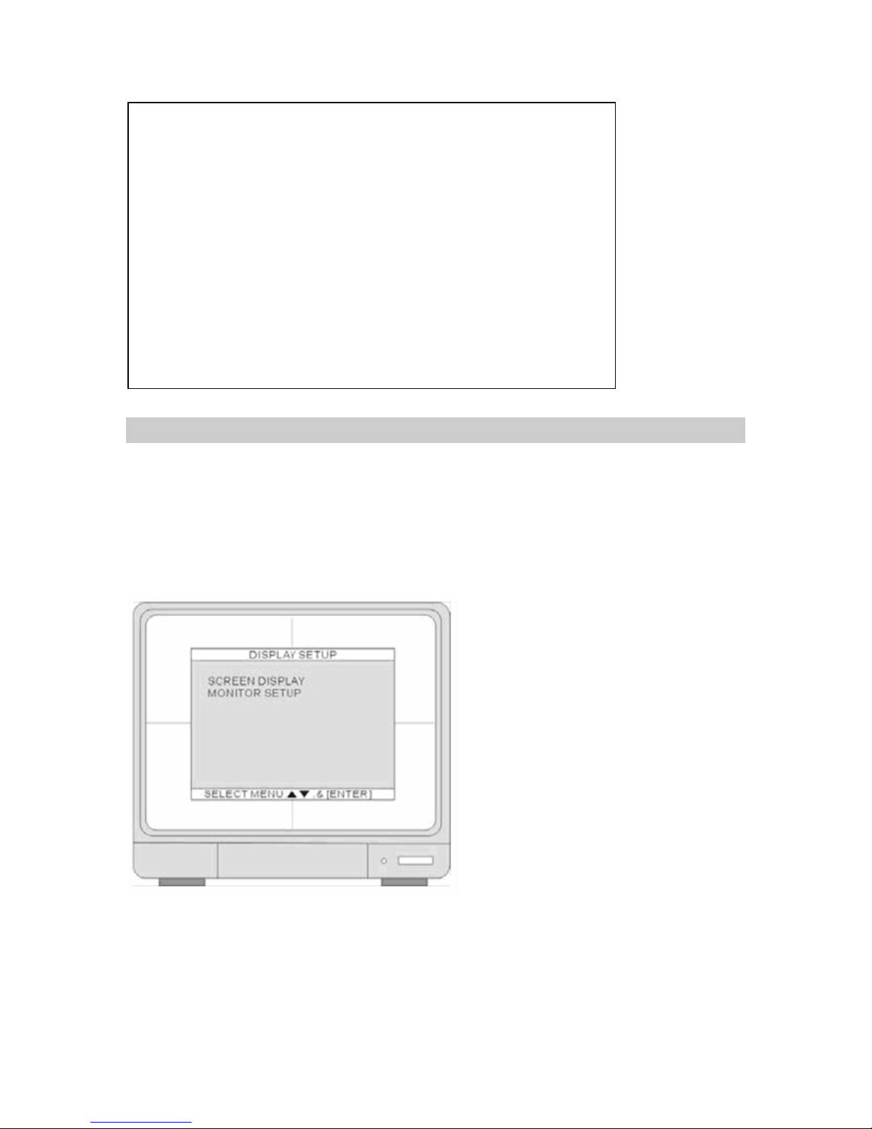
DISPLAY SETUP
1. SCREEN DISPLAY
• Set up your screen display for Live and Playback mode.
2. MONITOR SETUP
• Adjust the VGA display resolution and the monitor color.
32
Page 33
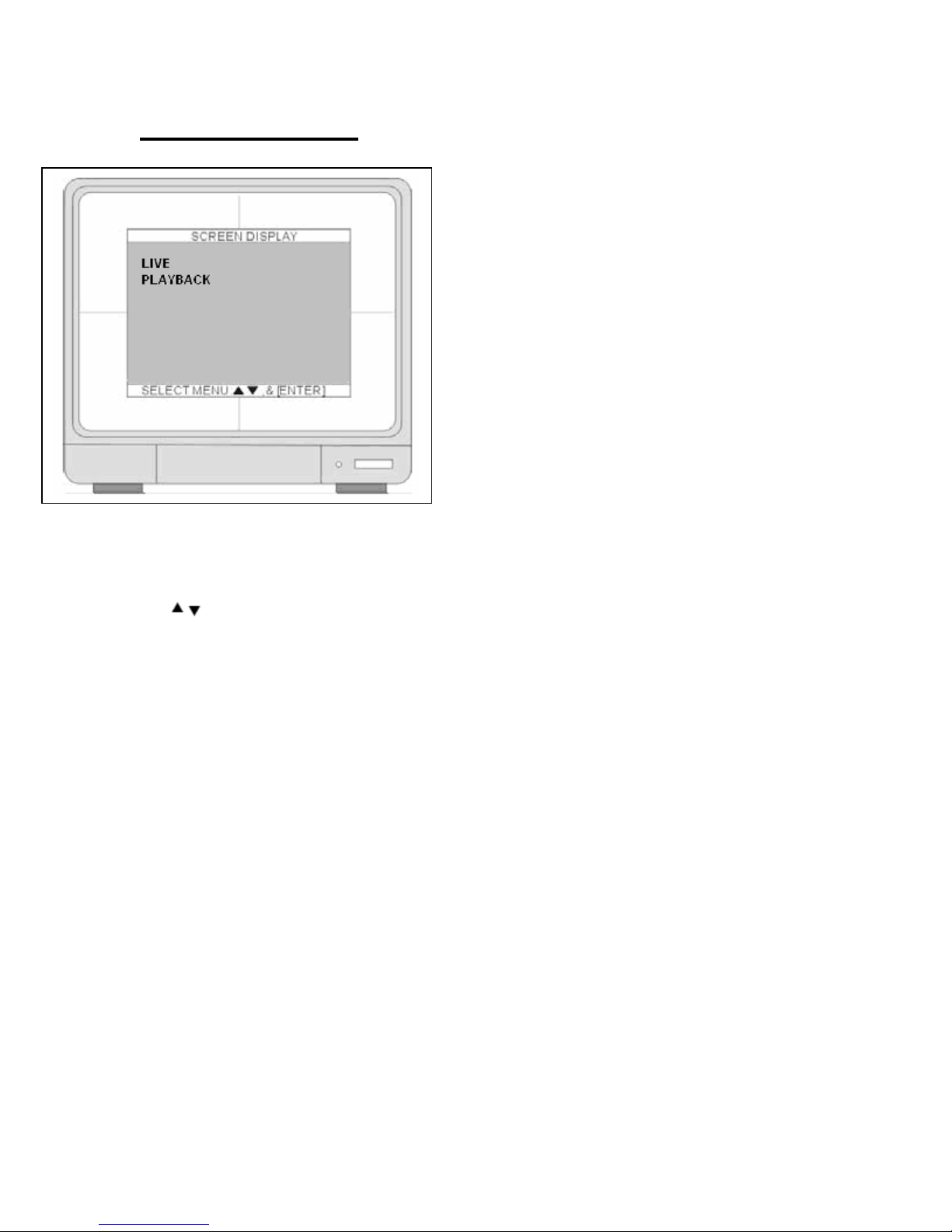
SCREEN DISPLAY
Use
LIVE and PLAY BACK.
UP DOWN arrow keys to select an item and press the ENTER key to select between
1. LIVE
Set up LIVE mode.
• TIME/DATE – Display the time and date. (ON) or (OFF)
• ICON DISPLAY - Display the cue icons on screen (ON) or hide (OFF).
• DVR STATUS - Display the recording status on screen. (ON) or hide (OFF)
• REC/PLAY BAR - Display HDD recording percentage. (ON) or hide (OFF)
• CAMERA TITLE - Display camera title. (ON) or hide (OFF).
2. PLAYBACK
Set up PLAYBACK mode.
• TIME/DATE- Display time and date. (ON) or hide (OFF).
• DVR STATUS- Display cue icons on the screen. (ON) or hide (OFF).
• REC/PLAY BAR- Display HDD recording percentage. (ON) or hide (OFF).
• CAMERA TITLE- Display camera title. (ON) or hide (OFF).
Example of settings below:
33
Page 34

MONITOR SETUP
1. VGA SETUP
• Set up the VGA resolution.
2. COLOR BAR TEST
• Adjust monitor colors with monitor controls.
• VGA resolution setup:
1024*768/60HZ、800*600/60HZ、640*480/60HZ、
1024*768/75HZ、800*600/75HZ、640*480/75HZ
34
Page 35

CONFIGURATION
1. HDD MANAGEMENT
• Menu options. HDD SETUP (HDD Clear), and HDD INFORMATION.
2. TIME/DATE SETUP
• Program the system date and time.
3. CAMERA SETUP
• Menu options. CAMERA TITLE, CAMERA
COLOR SETUP, CAMERA ACTIVE
SETUP, and MOTION SETUP.
4. INTERVAL SETUP
• Set up switch interval for Full screen and
PIP screen.
5. ALARM SETUP
• Set up Alarm mode (N.C. or N.O) and
Alarm Output Duration.
6. EVENT POPUP SETUP
• Set up POP-UP function for selected
cameras. ON or OFF: When ON, will display full screen on alarm trigger or motion detection.
7. BUZZER SETUP
• Set Buzzer ON or OFF for ALARM or MOTION options.
8. PASSWORD SETUP
• Setup the password.
35
Page 36
※ Default password: ADMIN: blank (No default password. Press ENTER key directly to enter
the system). You can change ADMIN password “See “PASSWORD SETUP” “to change your
password.
9. SYSTEM INFORMATION
• System information/ version of S/W and H/W, HDD
model number, and CD-R model number.
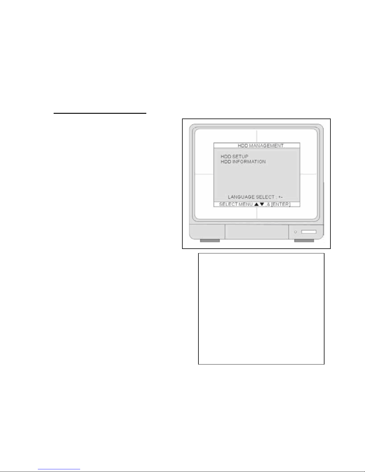
HDD MANAGEMENT
1. HDD SETUP
2. HDD INFORMATION
1. HDD SETUP
• BEGIN
Displays recorded start date/time for HDD.
• RECORD
Displays recorded end date/time for HDD.
• PLAY
Displays playback date/time for HDD.
• STATUS-
Displays HDD status.
(EMPTY/NORMAL/OVER WRITE)
CLEAR HDD
•
Clears HDD data.
36
Page 37
2. HDD INFORMATION
• Displays HDD (Master/Slave) information.
TIME/ DATE SETUP
1. To setup TIME/ DATE SETUP go to SYSTEM MENU select CONFIGURATION, and go to
TIME/DATE SETUP. Hit the ENTER key.
The date and time set by the manufacturer maybe different from your time zone. It is very
important to set up the system date and time before the DVR starts recording.
Set the date and time by using direction
buttons and [-] [+] button or Jog shuttle.
37
Page 38
NOTE: DO NOT change the date and
time after the recording starts it may
and cause playback errors.
• Date format- Asia/American/European
Time format- 12 hours/24 hours
Month format- English/Numeric
2. Use American, Use 12 hours or 24
hours, use English.
NOTE:
NOTE: DO NOT change the date and time after the recording starts it may corrupt DVR data
and cause playback errors. If it is necessary to change date and time after the
recording starts, please run the above steps to avoid playback errors.
We strongly suggest completin g the following settings at the initial setup.
• Set up the time/date, and RUN all factory defaults.
• Go to HDD management and CLEAR HDD
• “RUN” all factory defaults.
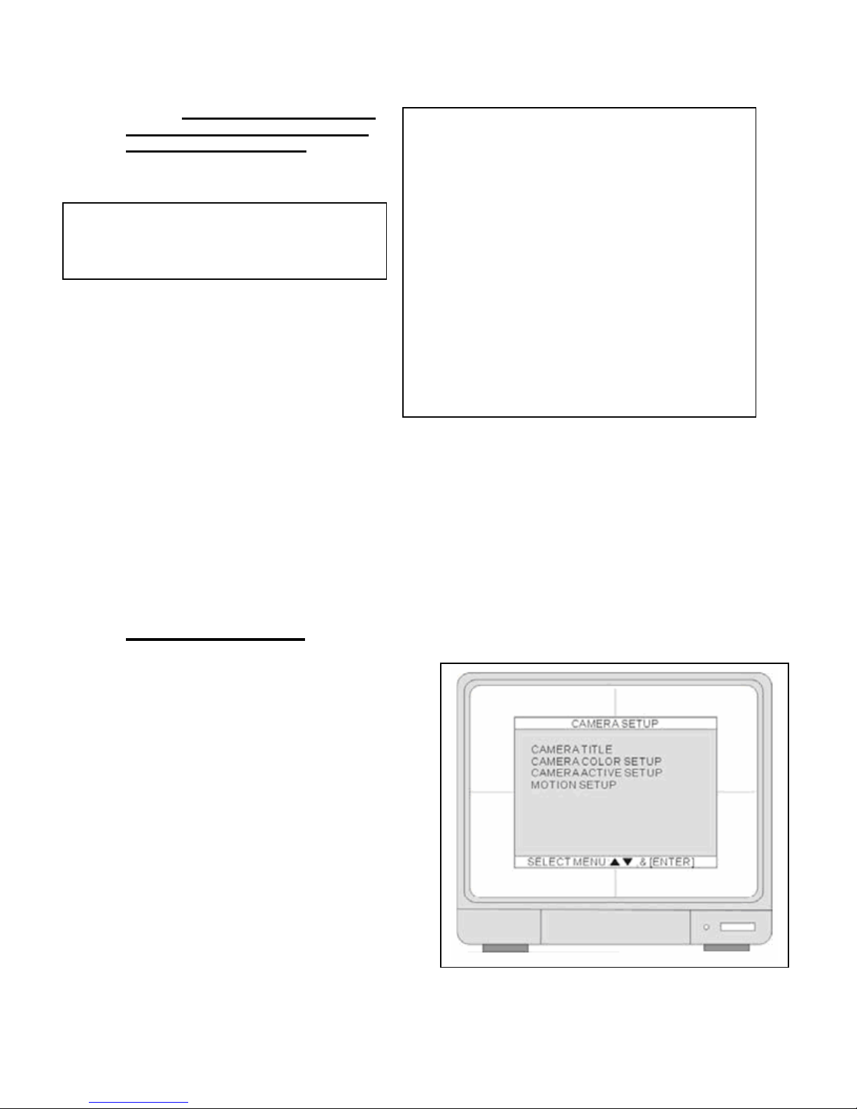
CAMERA SETUP
1. CAMERA TITLE
• Set up the camera title.
2. CAMERA COLOR SETUP
• Set up the camera color.
3. CAMERA ACTIVE SETUP
• Turn the camera ON or OFF.
4. MOTION SETUP
• Program the motion parameters and the
detection area.
38
Page 39

1. CAMERA TITLE
• Enter camera Title, max. 8 characters.
Using Left or Right arrow keys and
[-][+] buttons to change value and press
Enter. To return to the previous menu,
press the MENU key.
2. CAMERA COLOR SETUP
Adjust the image color: Use UP and DOWN to
select an item and use [-] and [+] or Jog shuttle
to adjust the values.
• CHANNEL: Select the camera to be modified.
• BRIGHTNESS: Adjust image brightness
(-32~31).
• CONTRAST: Adjust color contrast (-32 ~31).
• SATURATION: Adjust color saturation
(-32~31).
• HUE: Adjust color hue (-32~31).
3. CAMERA ACTIVE SETUP
• Use the direction buttons to select an item
and press ENTER to select ON and OFF
Example:
If you set LIVE OFF and RECORD ON:
After your setup, the playback will display, your live
picture will not and the recoding will continue.
39
Page 40

1. STATUS
• Display camera status: ACTIVE means video input status is normal, and LOSS means the
video is lost.
2. LIVE
• Set channel to display live video ON or OFF.
3. REC
• Set channel to record video ON or OFF.
4. MOTION SETUP
1. MOTION CONFIGURATION
2. MOTION MASK SETUP
40
Page 41
MOTION CONFIGURATION
1. CHANNEL
• Select channel for motion setup.
2. SENSITIVITY GRADE
• Adjust motion detection sensitivity. 1
(LOW) ~ 4 (VERY HIGH)
3. MOTION DISPLAY TYPE
Use MOTION DISPLAY TYPE to setup
visual indicators to give you more visibility to
help identify motion targets.
• BOX- display block
• CELL- display green lattice
• OFF – Will not indicate motion area
with BOX or CELL display.
• CELL- display green lattice ON. Hit
ENTER key to activate.
• BOX- display block ON. Hit ENTER Key to
activate.
41
Page 42

4. RECORD DURATION
• Set motion RECORD DURATION time.
o Motion continuously records through-out event occurrences, and last motion
event.
• Example:
o Motion RECORD DURATION is set for 10 seconds.
o DVR detects motion for 3 minutes.
Result: The DVR will record for 3 minutes and 10 seconds.
5. NUMBER OF CELLS TO DETECT
• Select how many cells need to be activated to start motion recording. Setting this
number to one will only require only one cell to activate motion recording. Setting this
number to 16 will require 16 or more cells to activate motion recording.
MOTION MASK SETUP
Set up area to detect motion.
• Select the number button to select the channel.
• Set motion detection area. Use the Direction buttons to move the cursor and press the
ENTER key to mark the area.
• Press the MODE Key to change the editing mode. The editing modes are below:
1. Cell: Move to the desired location and press the ENTER key to activate or deactivate the
motion detection in the marked area cell by cell. Grey area marks area where motion
detection is not needed.
2. ALL ON: Change the mode to ALL ON and press the ENTER key to activate the motion
detection for the complete window.
3. ALL OFF: Change the mode to ALL OFF and press the ENTER key to deactivate the motion
detection for entire window. Entire screen will be grayed out.
42
Page 43
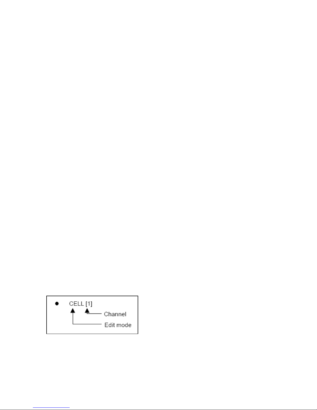
4. BLOCK ON: Is a quick way to active cell blocks for motion detection. You should turn off all
the cells by selecting ALL OFF and use the BLOCK ON function to activate the desired area
for motion detection.
5. BLOCK OFF: This function is the opposite of the BLOCK ON function. You should turn on all
the cells by selecting ALL ON and use the BLOCK OFF function to deactivate the desired
area.
43
Page 44
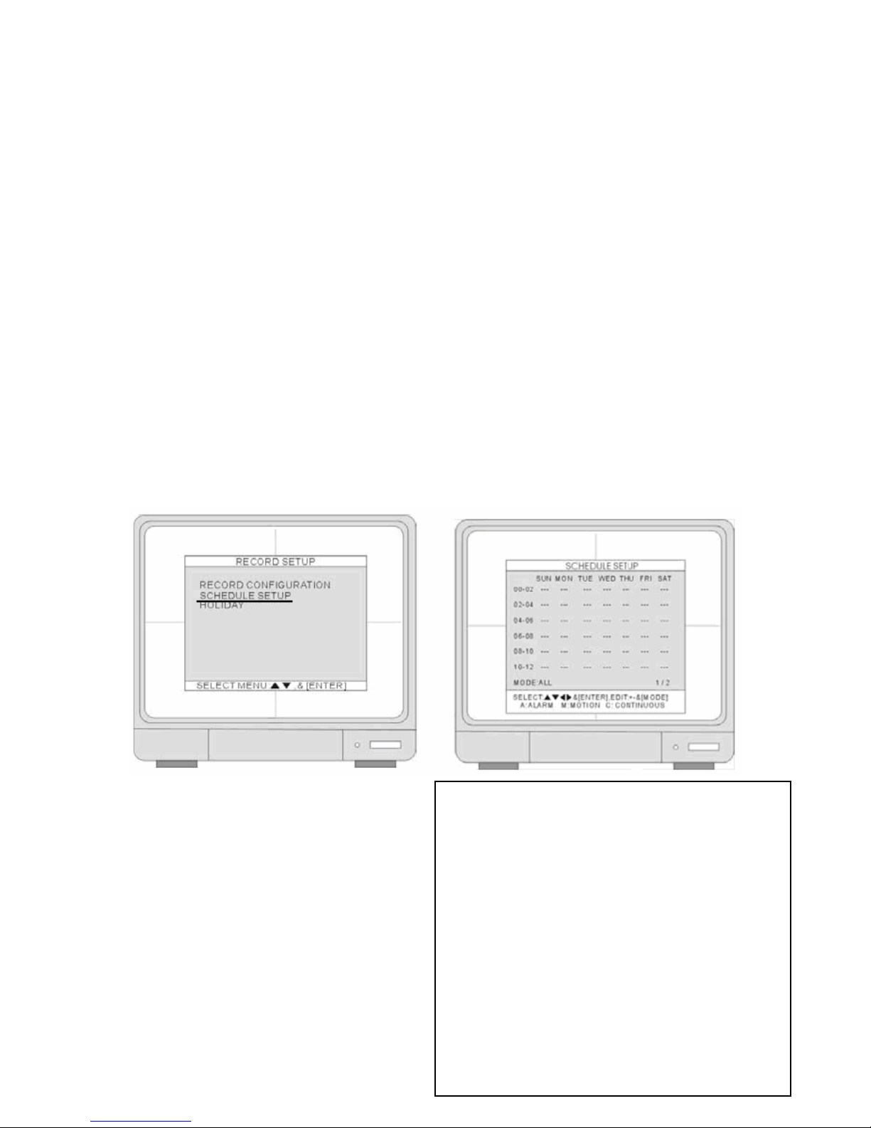
Note: Don’t forget to go to RECORD SETUP > SCHEDULE SETUP and change record mode to
MOTION to activate the motion settings.
SCHEDULE SETUP
20. Hit the ENTER key.
1. Hit the – minus key.
Your monitor screen should look like this,
showing the character M’s indicating motion
detection.
44
Page 45
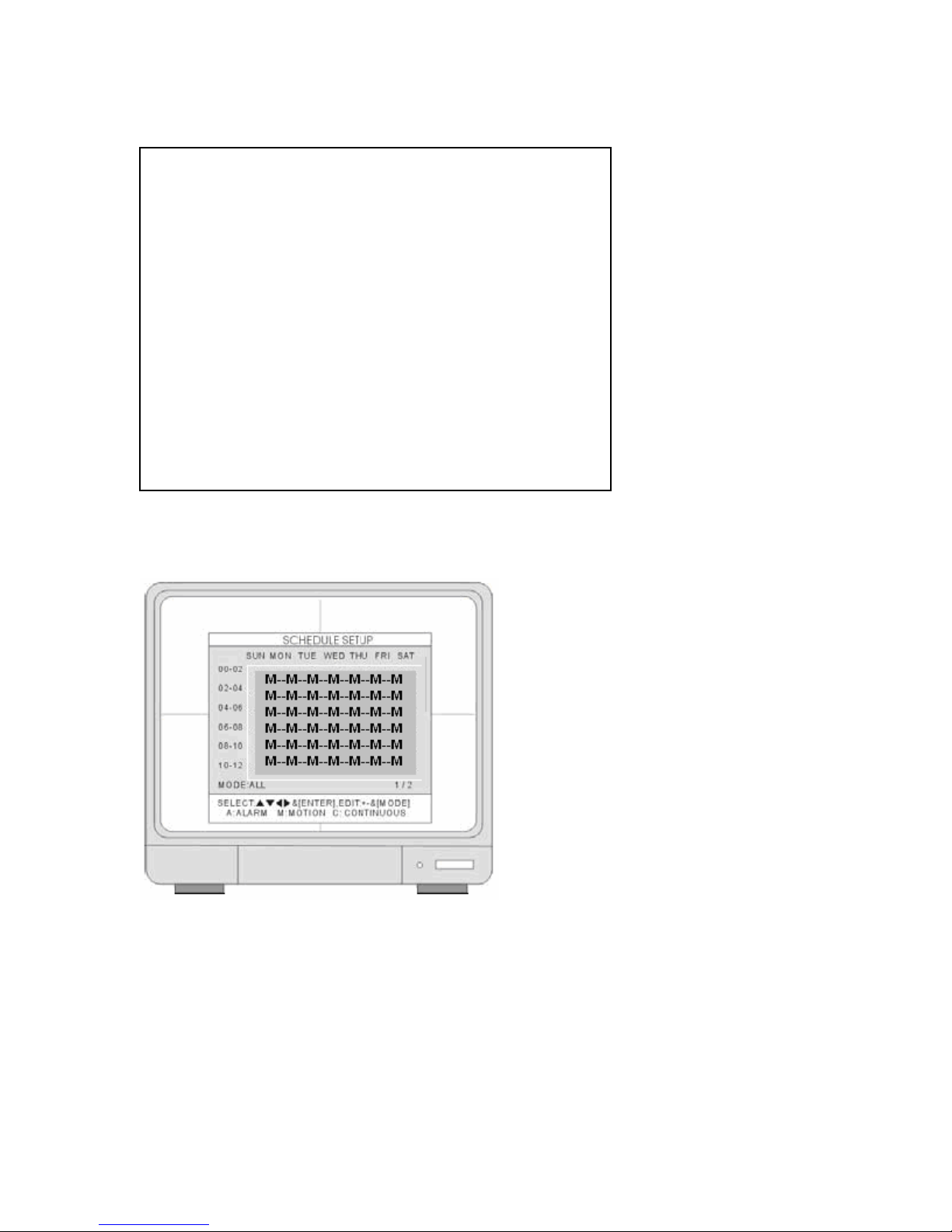
2. If not press the Mode key.
• MODE: Press MODE to select an editing mode. Continue till you see MODE : ALL at
bottom of screen, then press [+] and [-] to select a recording mode M.
45
Page 46

INTERVAL SETUP
1. SWITCH INTERVAL
• FULL- Full Screen Sequence Interval
setup. (Range: 1~99 SEC). Set up the
time to display each video sequence
before moving on to next camera
display.
• PIP- Picture in Picture, the sub-
picture’s sequence interval setup.
(Range:1~99 SEC)
PIP VIEW
• In full screen mode, press “PIP” to enter PIP mode.
• Press “PIP” again to cancel.
2. EVENT RECORD
• EVENT UPDATE TIME - is used to avoid recording the same event. The event types
include alarm, motion and video loss. Example when an event is triggered the same
event keeps on being triggered for a period of time. With the help of EVENT UPDATE
TIME, whenever there is an event the DVR records the starting time and the information
of the event in the Event Log ignores the following events within the duration set in the
EVENT UPDATE TIME. The setting range of the Event Update time is from 10 seconds
to 990 seconds.
46
Page 47

ALARM SETUP
1. CHANNEL
• Use [+] and [-] to select a channel.
2. ALARM INPUT
Set up the Alarm Input type.
• N.C- when the alarm is triggered, the
switch is closed (ON).
• N.O- when the alarm is triggered, the
switch is opened (OFF).
3. DURATION
• Set up a post- alarm recording duration
and the alarm output duration. The
duration setting is applied to both
functions. The setting range is from 1
second to 300 seconds.
Note: Alarm output can be triggered by an alarm input and video loss. Internal Motion detection
cannot trigger an alarm output.
EVENT POPUP SETUP
1. CHANNEL
• Use [+] and [-] to select a channel.
2. POPUP ON/OFF
• Set up the POPUP function ON/OFF: Use [+]
and [-] to select ON or OFF. When there is
an event, the screen display will switch to a
full screen of the corresponding channel.
3. EVENT
• Use [+] and [-] to select the event type that
will trigger the POPUP:
A- Alarm / M- Motion / AM- Alarm or Motion.
4. DURATION
• Use [+] and [-] to set up a duration of the
POPUP. The setting range is from 1
second to 60 seconds.
47
Page 48

BUZZER SETUP
Select alarm conditions to trigger BUZZER. Use UP and
DOWN Keys to select trigger and press ENTER to turn
ON or OFF the selection.
1. ALL
• Select ALL alarm conditions to trigger
BUZZER. Turn BUZZER ON or OFF.
2. KEY BEEP
• Turn beep on/off while operating the front
panel.
3. VIDEO LOSE
• Turn beep on/off at the video loss.
4. ALARM ACTIVE
• Turn beep on/off when alarm is triggered.
5. MOTION DETECT
• Turn beep on/off when motion is detected.
1. To turn buzzer off, press any key on the front panel.
2. The beeping sound can only be turned off manually.
PASSWORD SETUP
The password consists of 1 to 8 digits. Press the
number keys on the front panel to enter the password.
1. USER ID
• Press or to set User ID.
2. USER PW
• Key in the current password.
NOTE: DEFAULT password is blank (________), so
leave blank when changing ADMIN password.
3. NEW PW
• Key in the new password.
4. CONFIRM PW
• Enter the new password again for
confirmation.
NOTE: Default password:
ADMIN: (NULL) or Blank (_________) / MANAGER: “1” / USER1: “2” ~ USER8: “9”
48
Page 49
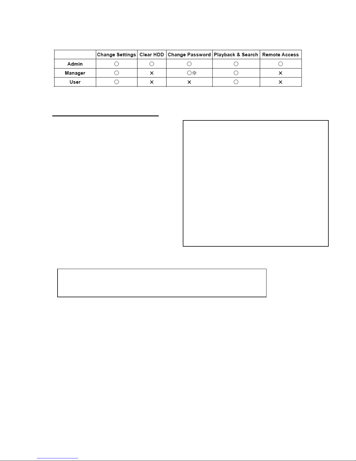
NOTE: You have three user levels.
SYSTEM INFORMATION
Displays system information and status.
1. S/W VERSION
Displays the firmware version
2. H/W VERSION
Displays the PCB version
3. PRODUCT ID
Displays the product ID number
4. MASTER
Displays MASTER HDD information.
5. SLAVE
Displays SLAVE HDD information.
6. CD-R
Displays CD-R information.
NOTE: The product ID is not the MAC address. MAC address can be found in
[EXTERNAL DEVICE] > [TCP/IP setup].
49
Page 50

RECORD SETUP
1. RECORD CONFIGURATION
• Set up overwrite, recording mode, picture
quality, resolution, and recording speed.
2. SCHEDULE SETUP
• Program the recording schedule.
3. HOLIDAY SETUP
• Set up holidays, max. 100 days.
RECORD CONFIGURATION
Use UP and DOWN arrow keys to select an
item. Use [+] and [-] to change the value.
1. OVERWRITE
• ON: When the hard drive is full, the system
will overwrite the earliest recorded video. If
the DVR has two hard drives, the
overwriting starts from the Master drive.
• OFF: The system stops recording when the
hard drive is full. If the DVR has two hard
drives, the system stops recording when the
Master and Slave drive both are full.
2. MUTIPLEX
Set up the multiplex mode
• Duplex: allows recording and remote connection simultaneously. Stops recording when
you enter playback.
•
※During the remote connection, the DVR keeps recording if the client stays in the LIVE
mode. Stops recording when remote client enters the playback mode.
Triplex: record and playback simultaneously. The DVR keeps reco rding while
the DVR enters playback either locally or remotely. In Triplex mode recording and playback
speed is reduced by 50%. Audio will not work in Triplex mode.
50
Page 51
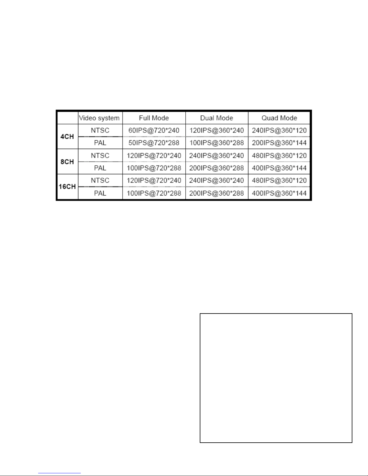
3. QUALITY
Set up the recording picture quality
• Quality level:
o 4CH/ 8CH and 16CH: Low / Mid / High / Super / Hyper
o Some models: 8CH and 16CH: Basic / Normal / Enhanced / Fine / Super Fine.
4. RESOLUTION
By lowering the resolution, you increase the recording speed but reduce the picture size.
※IPS (Images Per Second)
To change the DVR recording duration, refer to: Line items 5.6. and 7.
5. RECORD IN ALARM
• Set the recording speed when alarm is triggered.
6. RECORD IN MOTION
• Set the recording speed when motion is detected.
7. CONTINUOUS RECORD
• Set the recording speed for continuous recording.
RECORDING SPEED
1. The recording speed is expressed in fractions.
• 1/ 1 ratio is recording at full speed,
• 1 / 2 ratio is recording at half of the
recording speed. At 1/2, the recording
duration will be two times longer.
• 1 /3 ratio is recording at one third of the
recording speed. At 1/3 the recording
duration is three times longer.
• You can select different parameters from
1/1, 1/2, 1/3, 1/4,… to 1/999.
51
Page 52

NOTE:
1. To increase recording time lower your recording speed, this will reduce your IPS (Images per
second).
2. When using QUAD Mode your recording speed are limited to 1/1, 1/2, and 1/3.
3. All active cameras share the recording speed. Turn off all unused camera channels to
maximize your video recording quality and performance. To turn off camera channels refer to
SYSTEM MENU
Please note that channels with video loss are still active, recording and sharing the recording
speed and reducing optimal performance .
CONFIGURATION CAMERA SETUP CAMERA ACTIVE SETUP.
SCHEDULE SETUP
Program a recording schedule.
MODE: Press MODE to select an editing mode. Use the direction keys
cursor, and then press [+] and [-] to select a recording mode.
to move the
52
Page 53

SCHEDULE SETUP
Editing modes:
• TIME CELL: Program the schedule at a two-hour interval.
• TIME ZONE: Program the schedule by time zone. There are 12 Time Zones adding up
to 24 hours. A time zone is a two-hour interval.
• WEEK: Program the schedule day by day.
• ALL: The DVR records at one recording mode, 24 hours a day, and 7 days a week.
• CLEAR ALL: Clear all the schedule settings.
• NEXT: Go to the next page. The first page is from 00-12 hours, and the second page is
from 12-24 hours.
Set up a recording mode:
• A--: Set ALARM to record when triggered.
• -M-: Set MOTION to record when motion is detected.
• --C: Set CONTINUOUS record to record continuously.
• AM-: Set AlARM + MOTION to record when activated.
• A-C: Set AlARM + CONTINUOUS record. Records continuously at the speed set in
CONTINUOUS RECORD, and switches to the speed set in
• RECORD IN ALARM when there is an alarm triggered.
• -MC: Set MOTION+ CONTINUOUS record. The DVR records continuously at the speed
set in CONTINUOUS RECORD, and switches to the speed set in RECORD IN MOTION
when there is motion detected.
1. If MOTION RECORDING keeps recording continuously or does not record, check the
sensitivity settings and the motion mask setup in CONFIGURATION>CAMERA
SETUP>MOTION SETUP.
53
Page 54
2. If the motion settings are too sensitive, you may want to lower the sensitivity level and define
a motion detection area for more accuracy. If the motion is not triggered, you may want to
increase the sensitivity level, clear the motion mask, or enlarge the detection area.
HOLIDAY SETUP
Set up holidays. You can program up to
100 days for holidays. The recording
schedule of the holidays is the same as
the settings for SUNDAY in SCHEDULE
SETUP.
• Press MODE Key and set the
editing mode as EDIT HOLIDAY.
Use direction keys to
select and press the ENTER key
to mark the day as a holiday.
• To clear the settings, press
MODE to set the editing mode to
CLEAR ALL DATA or CLEAR
MON DATA (clear month by
month). Press ENTER to clear the
settings.
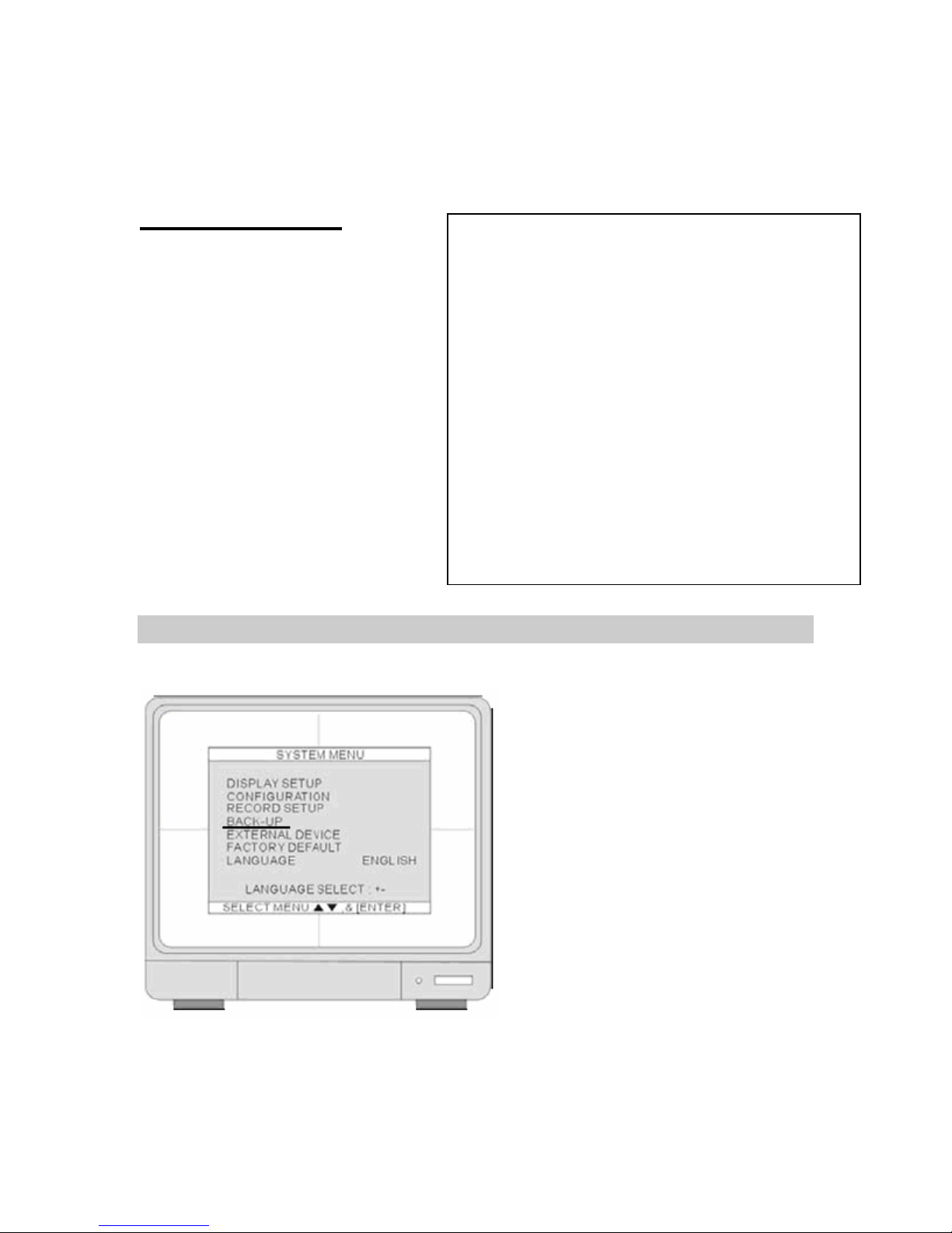
BACK-UP
Go to SYSTEM SETUP>BACK-UP>CD/DVD SETUP.
54
Page 55

CD/DVD SETUP
1. HDD
• Displays HDD start and end recording time and date.
2. CD/DVD
• Select a starting date and time for backup. Press the ENTER key and use the UP
and DOWN arrow keys to move the cursor. Use [+] [-] or J.Shuttle to change the value.
Press the ENTER key and then press
backup size.
the down arrow key and go to SIZE to choose a
3. SIZE
• Insert a blank CD/DVD disk. Disk size will
display on screen. Press the ENTER key
to enter the SIZE selection. Use [+] [-] or
J.Shuttle to change the value. Press the
ENTER key and the DVR calculates the
end date and time for backup
automatically.
※ Use CD-R or DVD+R (CD-RW and DVD-RW
discs will not work) CD’s only for backup.
Note: Reads CD-R and DVD+R disc (CD-RW
discs will not work with this unit). Does not read
DVD-R, DVD+RW. DVD-RW.
NOTE:
1. Use a new blank CD. Do not format or reuse a CD. Do not reuse rewritable CD’s. (RW discs
will not work).
2. When choosing a backup size, leave 20MB as a buffer and do not use entire CD capacity.
For example, if your CD size is 700M enter 650 in SIZE setup.
3. Once the DVR starts burning CD do not press any keys to stop process. When the burning
is completed, the DVR will eject CD automatically.
55
Page 56

※BACKING UP, takes a little time to load, please wait till CD ejects.
4. BURN
• Move the cursor to BURN and press the ENTER key to start the backup. System will
save the file in AJP format. You will have to install the BACKUP PLAYER software to
playback the backup file on your PC.
CD/DVD Backup Player software installation
1. Insert software CD.
2. Click Install backup player
to start the installation.
3. Select a Destination Folder
4. Copy files to the Destination
folder. System will build a new
icon for CD BACKUP
PLAYER. Double click on
icon for CD Backup Play er
located in Desktop.
5. You don’t necessarily need to
use the backup player
software to view your CD
backup data. When you burn
a CD using the DVR, the DVR
will automatically attach
“VIEWER software” to the
burnt CD. You can load the
CD on any DVD or CD player
and play your backup video.
56
Page 57
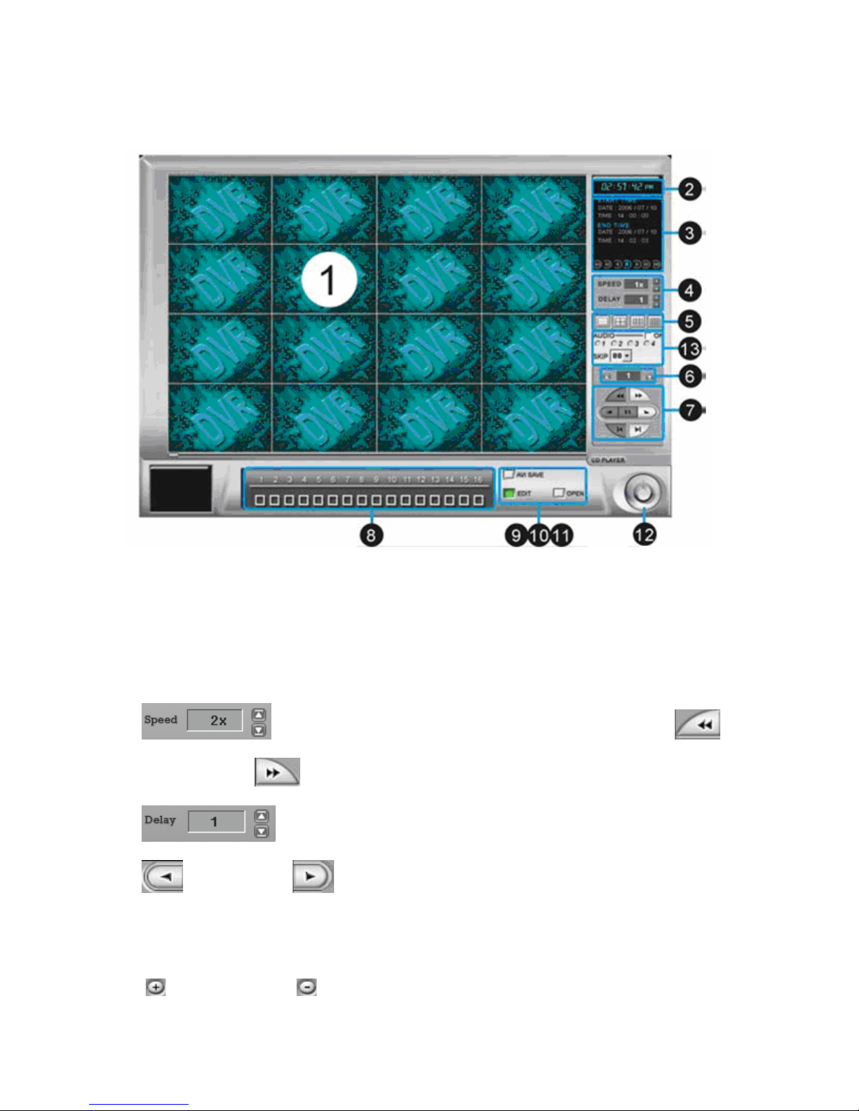
CD/DVD Backup Player software interface
1. Display screen: To display the backup image
2. Time display: To indicate the current time
3. Information window: To indicate the CD’s start/end time and date, and the backup video
quality (resolution).
4. Speed Adjustment:
Fast Rewind and
for Rewind and for Forward.
Select a playback speed (2X, 4X, 8X,16X, 32X, 64X)and press
Fast Forward.
Select a speed to play slow motion (1/2X, 1/4, 1/8X, 1/16X) and press
5.
6.
: Select a [1 / 4 / 9 / 16] Screen display
Go to the next page : Go to the previous page
57
Page 58
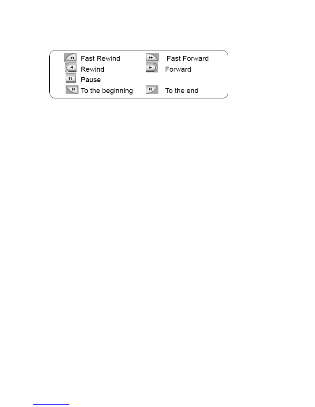
7. Function button:
8. Channel selection: To select a single channel from CH1 to CH16
9. AVI SAVE: To save the backup video to AVI format
10. EDIT: To open the dialog window to save a single frame as a JPEG file or print out.
11. Open: To open the backup file from CD-R or DVD+R
. EXIT: To exit the program
12
13. Audio function: Click ON and then select a channel to play audio.
• ON: Start playing audio, and it will automatically switch to full screen
• 1~4: Select Audio channel.
• SKIP: To synchronize video and audio play speed. When DVR recording is set to a lower
speed, adjust SKIP to synchronize the video and audio.
o Example 1. The DVR recording is set to 1/3X, set SKIP at 3.
o Example 2. When the DVR recording is set to 1/4X, set SKIP at 4.
Open AJP file
1. Select an AJP file and press the OPEN button and Windows will open your file.
58
Page 59
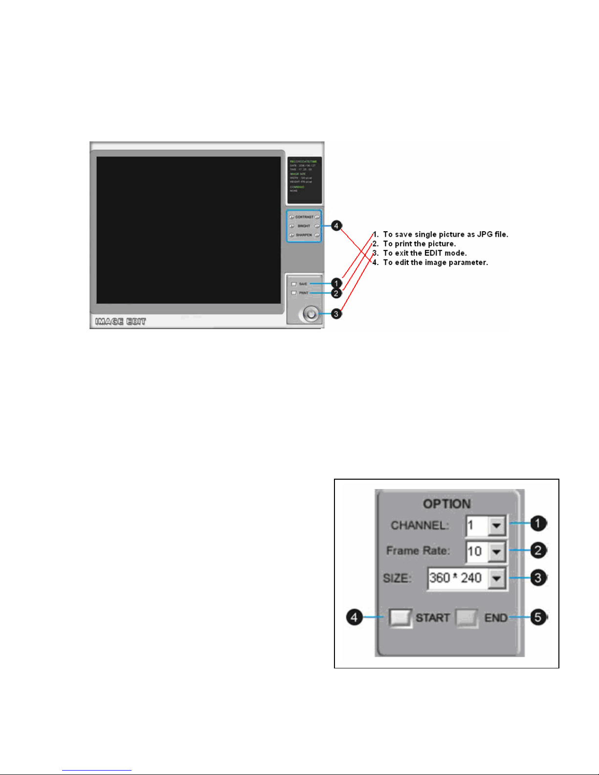
Save JPG file
1. Click EDIT during playback to save image in FULL SCREEN MODE.
2. Select SAVE to save the picture as JPEG file or select PRINT to print the image.
Save as AVI file
During playback, you can save the backup file in AVI format.
1. Open backup file from your CD-R or DVD+R. Locate video and start saving the AVI file. Select
AVI SAVE to open the AVI SAVE dialog window.
2. Select the channel, frame rate, and AVI image size.
3. Select” START” to save and “END” to stop the process.
4. Click AVI SAVE again to close the AVI SAVE
dialog window.
1. CHANNEL: Select a channel to save
2. Frame Rate: Select how many frames to save
every second.
3. SIZE: Set the resolution as 360*240 or
720*480
4. START: Start saving AVI file
5. END: Stop saving AVI file
Note: The AVI SAVE will not include audio.
59
Page 60

EXTERNAL DEVICES
1. TCP/IP SETUP
• Set up TCP/IP settings.
2. RS232C SETUP
• Set up RS232 port settings.
3. PANTILT SETUP
• Set up PTZ control.
4. SPOT MONITOR SETUP
• Set up the oup put time.
5. AUDIO SETUP
• Audio record and play
TCP/IP SETUP
1. MAC ADDRESS
• MAC address is not editable.
2. IP ADDRESS
• Set up IP address.
3. IP PORT
• Set up IP Port.
4. GATEWAY
• Set up GATEWAY.
5. SUBNET MASK
• Set up SUBNET MASK.
6. DHCP SETUP
• Set DHCP mode to Manual or Automatic. When DHCP is set to Automatic, you can not
change IP settings. To turn off the DHCP automatic detection, exit this page and go to
DHCP SETUP to change the setting.
DDNS SETUP
60
Page 61

1. DDNS ON/OFF
• Press the ENTER key to turn DDNS ON or
OFF.
2. DNS SERVER
• Set up DNS Server’s IP address. Press the
ENTER key to enter the DNS SERVER. Use
UP and DOWN arrow keys to move
the cursor and [+] [-] or J.Shuttle to
change the value. Press the ENTER key to
confirm the settings and exit the selection.
3. INTERVAL
• Set up an interval for the DVR to report its
IP address to the DDNS server
automatically. (D- day / H- hour / M- minute).
Press the ENTER key to enter the selection
and [+] [-] or J.Shuttle to change the values. Press the ENTER key to confirm the
settings and exit the selection.
4. REGISTER
• Connect to DDNS server and register the DVR information. Press ENTER to start the
registration.
5. DNS STATUS
• Displays the current status of DDNS connection
IP ADDRESS: Set the server IP address.
IP PORT: Set the server IP port.
REMAIN TIME: Set time for reporting to the server.
6. LAST REGISTRATION DATE
• Indicate the time of the last registration.
CONNECTION SETUP
Use arrow keys to select and [+] [-] or
J.Shuttle to change the value.
1. TIMEOUT
• Set up the remote connection response
time. If the client does not receive a
response from the DVR, the client will
disconnect and try again. The setup range is
from 1 millisecond to 12,750 seconds.
2. RETRY COUNT
• Set up the number of times client should try
to reconnect to the DVR. The setup range is
from 0 to 20.
61
Page 62

DHCP SETUP
1. DHCP MODE
• Press the ENTER key to switch
DHCP to AUTOMATIC.
2. DETECT IP
• Press the ENTER key to start.
Press MENU to cancel the
detection.
RS232C SETUP
Set RS232 SETUP to communicate with serial
devices. Through the DVR RS232 port, users
can connect to a PC or other serial control
devices. The ASCII-Code guide is located in
Advance Hardware Installation under Serial
Hardware.
1. SPEED
• The transmission baud rate is
19200bps.
2. LENGTH
• The transmission length is 8 bits.
3. STOP BIT
• The stop bit is 1.
4. PARITY
• The parity is none.
62
Page 63

PANTILT SETUP
COMMAND SETUP
Press UP and DOWN arrow keys to select and [+] / [-] to change the value.
1. CHANNEL
• Select PTZ channel.
2. MODEL
• Select PTZ protocol.
3. PTZ ID
• Select PTZ ID.
4. BUADRATE
• Select Baud Rate.
5. CMD DELAY
• Set up delay time to send the command.
6. COMMAND
• Perform PTZ CMD.
63
Page 64

7. LENGTH
• Set up the segment for PTZ control code.
8. CODE
• PTZ CMD control code.
Please refer to PTZ Camera Control for more details.
SPEED SETUP
Press UP and DOWN keys to select
and [+] / [-] to change the value.
1. PAN SPEED
• Set the Panning speed.
2. TILT SPEED
• Set the Tilting speed.
3. ZOOM SPEED
• Set the IN/OUT speed for ZOOM.
4. FOCUS SPEED
• Set the speed for FOCUS.
SPOT SETUP
SPOT monitor setup
1. Sequence interval time
• To set up the interval time for sequence
display.
2. Alarm pop up
• Output to SPOT monitor when alarm is
triggered.
3. Motion pop up
• Output to SPOT monitor when motion is
triggered.
4. Pop up time
• Time duration for POP UP.
64
Page 65

AUDIO
1. Channel
• Channel your working with.
2. Record
• To set the record on/ off.
3. Play
• To set the audio on / off in
playback mode.
Note: the DVR will not play or record
AUDIO under the following conditions:
1. When the recording resolution is
configured to QUAD mode in
RECORD CONFIGURATION.
2. When the MUTIPLEX mode is configured to TRIPLEX in RECORD CONFIGURATION.
3. When playback is in rewind or fast-forward. The DVR plays AUDIO only when the playback
is in forward at 1X speed.
4. The DVR does not transmit AUDIO to the client.
65
Page 66
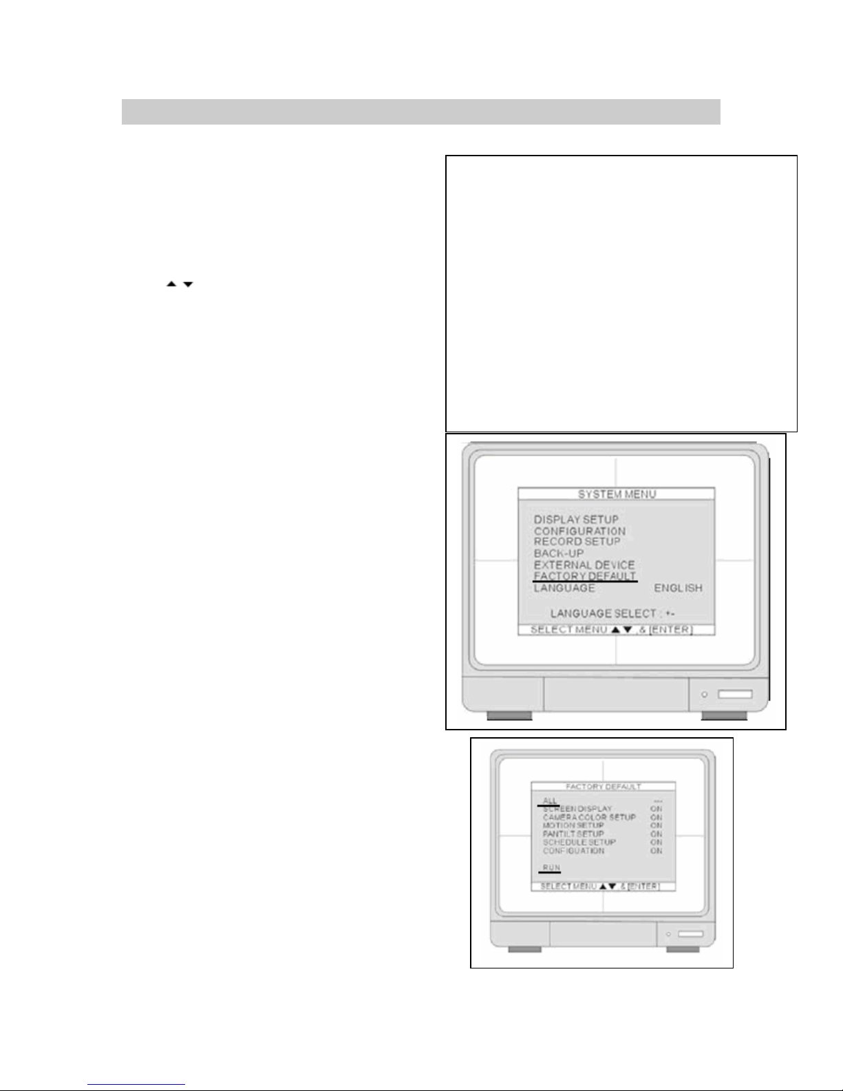
FACTORY DEFAULT
Press
Move the cursor to FACTORY DEFAULT and hit
ENTER.
Move the cursor to ALL and hit ENTER to turn all ON.
Move the cursor to RUN and press ENTER to execute
the Factory Default.
to “select” and ENTER for selection.
66
Page 67

1. ALL
• Set all the settings back to factory default.
2. SCREEN DISPLAY
• Set”SCREEN DISPLAY” back to factory default.
3. CAMERA COOLR SETUP
• Set”CAMERA COLOR SETUP” back to factory default.
4. MOTION SETUP
• Set”MOTION SETUP” back to factory default.
5. PANTILT SETUP
• Set”PANTILT SETUP” back to factory default.
6. SCHEDULE SETUP
• Set”SCHEDULE SETUP” back to factory default.
7. CONFIGUATION
• Set”CONFIGURATION” back to factory default.
FACTORY DEFAULT
ALL
SCREEN DISPLAY
CAMERA COOLR SETUP
MOTION SETUP
PANTILT SETUP
SCHEDULE SETUP
CONFIGUATION
RUN
LANGUAGE
Press [+] / [-] button to select a language
setting.
67
Page 68

ADV ANCE HARDWARE
INST ALLA TIONS
SPOT
SPOT: Second monitor
output. Once alarm or
motion is triggered, it will
automatically pop-up or
display in sequence
according to the set up.
Chapter
5
68
Page 69

LOOP
To monitor a single channel, connect the “loop out” of the corresponding channel to a monitor.
VCR
To record a specific channel, connect the “loop out” of the corresponding channe l to a DVR, VCR,
or recording device.
69
Page 70

SENSOR AND ALARM INSTALLATION
Input & Output
4 Channel
8 Channel
16 Channel
1. D1~D16 Alarm Input/GND for Location
• 16 Sensor inputs, for sensor input installation
2. Relay Output NO/NC/COM
• The application of relay output is NO+COM + NC+COM
70
Page 71
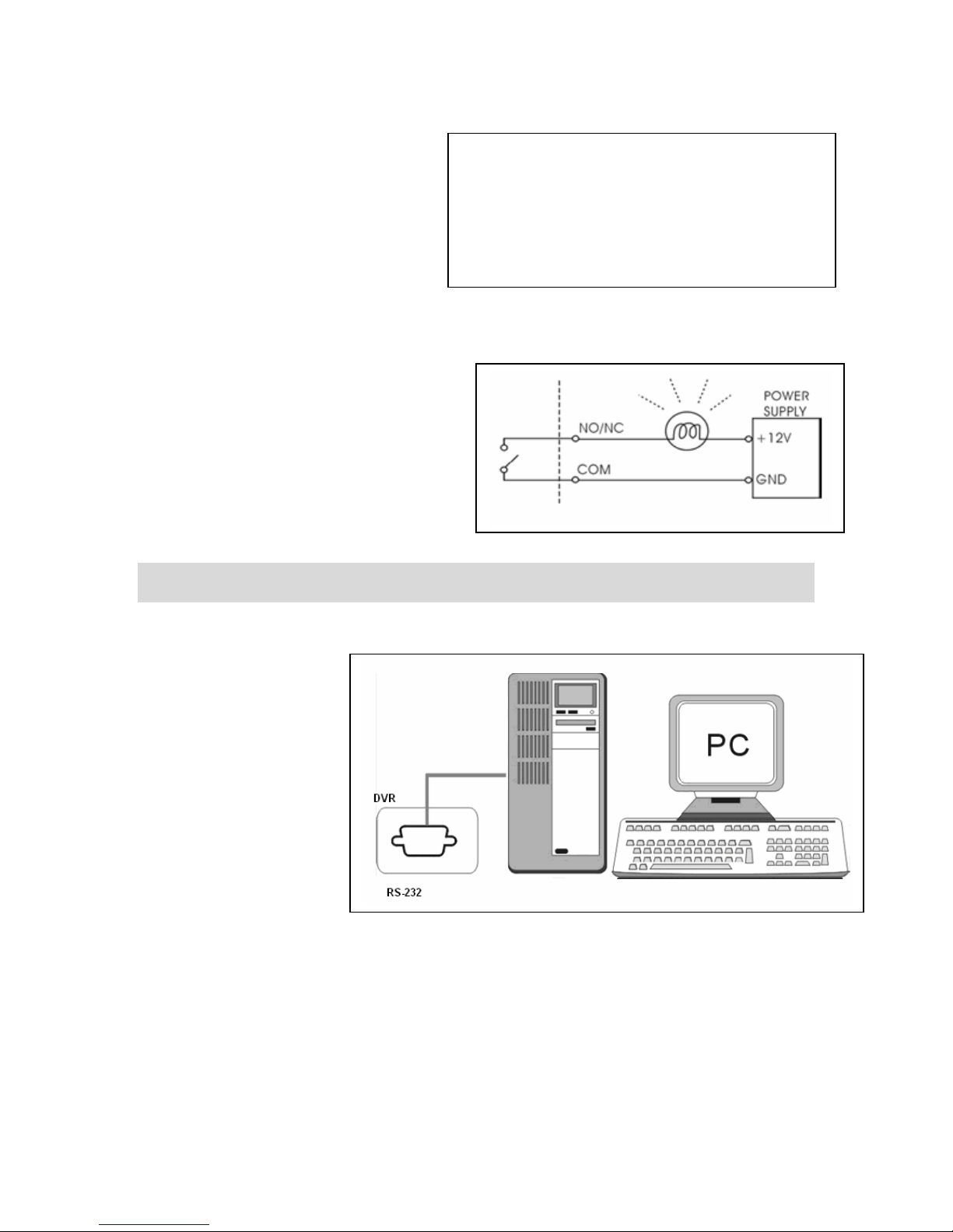
Sensor installation
• Alarm will be triggered once one
(or more than one) alarm input
(D1~D16) causes short circuit or
open circuit with GND.
Relay output installation
• Alarm output can be NO or NC.
• NO-COM: the NO and COM
terminals are open-circuit, and
closed-circuit when alarm triggered.
• NC-COM: the NC and COM terminals
are closed-circuit and open-circuit
when alarm triggered.
SERIAL PORT SETUP
• Connect PC COM port or other device to the DVR RS232.
• RS232 settings (baudrate/ parity/ length/ stop bit ) are NOT adjustable. The transmission
baud rate is 19200bps, length 8 bits, stop bit 1, and the parity is none.
• ASCII-CODE is 1 BYTE.
71
Page 72
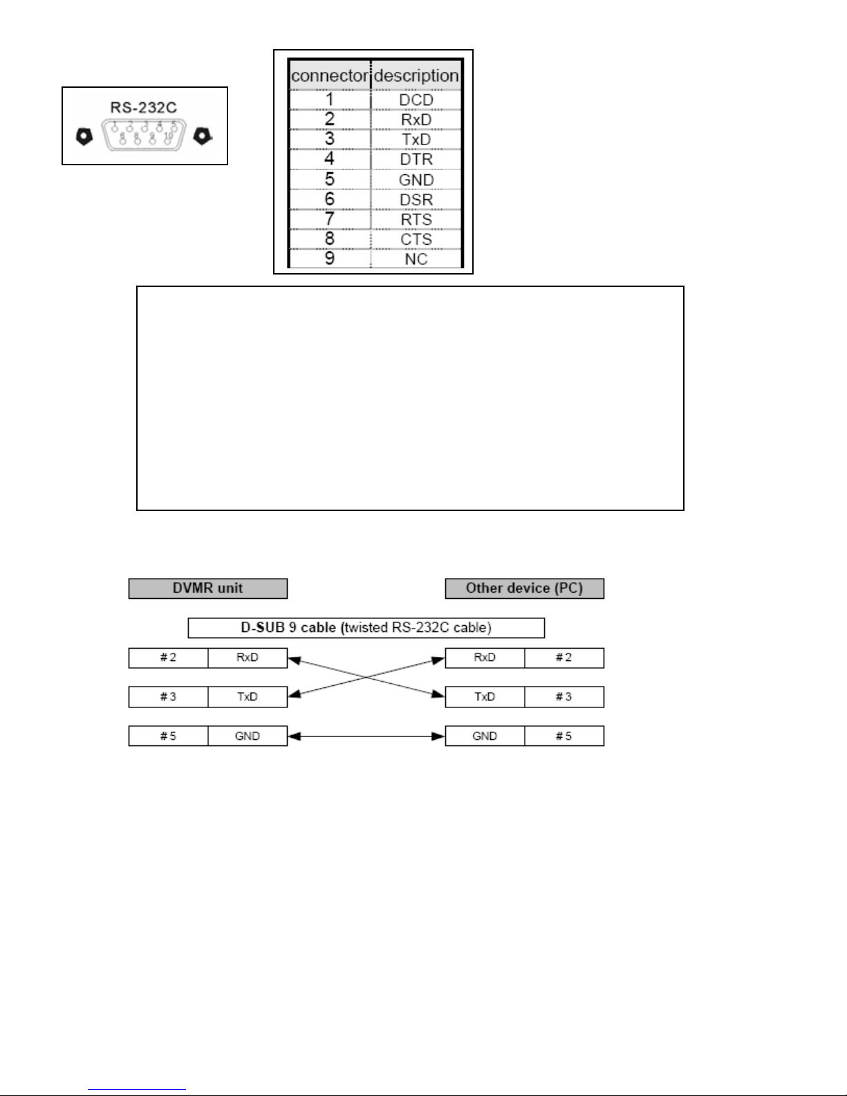
To connect DVR to a PC, users must use a twisted RS232 cable.
72
Page 73

PTZ CAMERA INSTALLATION &
OPERATION
• Connect the PTZ D+ to the DVR D+, PTZ D- to DVR D-.
4 Channel
8 Channel
16 Channel
73
Page 74

See PTZ camera manufacturer user manual for baud rate, protocol settings and camera
command settings. Enter the baud rate, protocol, and PTZ camera address suggested by the
manufacturer in PTZ setup.
To set PTZ menu settings go to:
SYSTEM MENU > EXTERNAL DEVICE > PANTILT SETUP > COMMAND SETUP
1. MODEL: select a PTZ protocol specified by PTZ camera manufacturer.
2. PTZ ID: enter the PTZ’s ID / address specified by manufacturer.
3. BAUD RATE: enter the PTZ’s transmission baud rate specified by the manufacturer.
4. CMD DELAY: the delay time of the command transmission between bytes. Please refer to the
PTZ user manual for the manufacturer’s suggestion.
PTZ CAMERA OPERATION
PTZ controls on front panel of DVR.
Press PTZ key and use MENU and NEXT key to select a PTZ command, and [+] [-] to select the
channel. Then, press PTZ key to enter the PTZ control mode.
1. Displays the channel connected to the PTZ camera.
PTZ Camera selection using [+] [-] keys: PTZ camera 1, 2, 3, …16, depending on DVR option
4, 8 or 16 channel.
74
Page 75
2. Displays PTZ command; press the ENTER key to send control code to PTZ.
PTZ command set using MENU and NEXT keys:
1. ZOOM OUT or IN.
2. FOCUS FAR, NEAR or AUTO
3. IRIS OPEN, CLOSED or AUTO
4. AUTO SCAN
5. PRESET GOTO , SET, CLEAR,
6. USER 1, 2, 3.
• You can also press the PTZ buttons on the front panel, and use the front panel pre-
assigned PTZ function keys to control the PTZ camera.
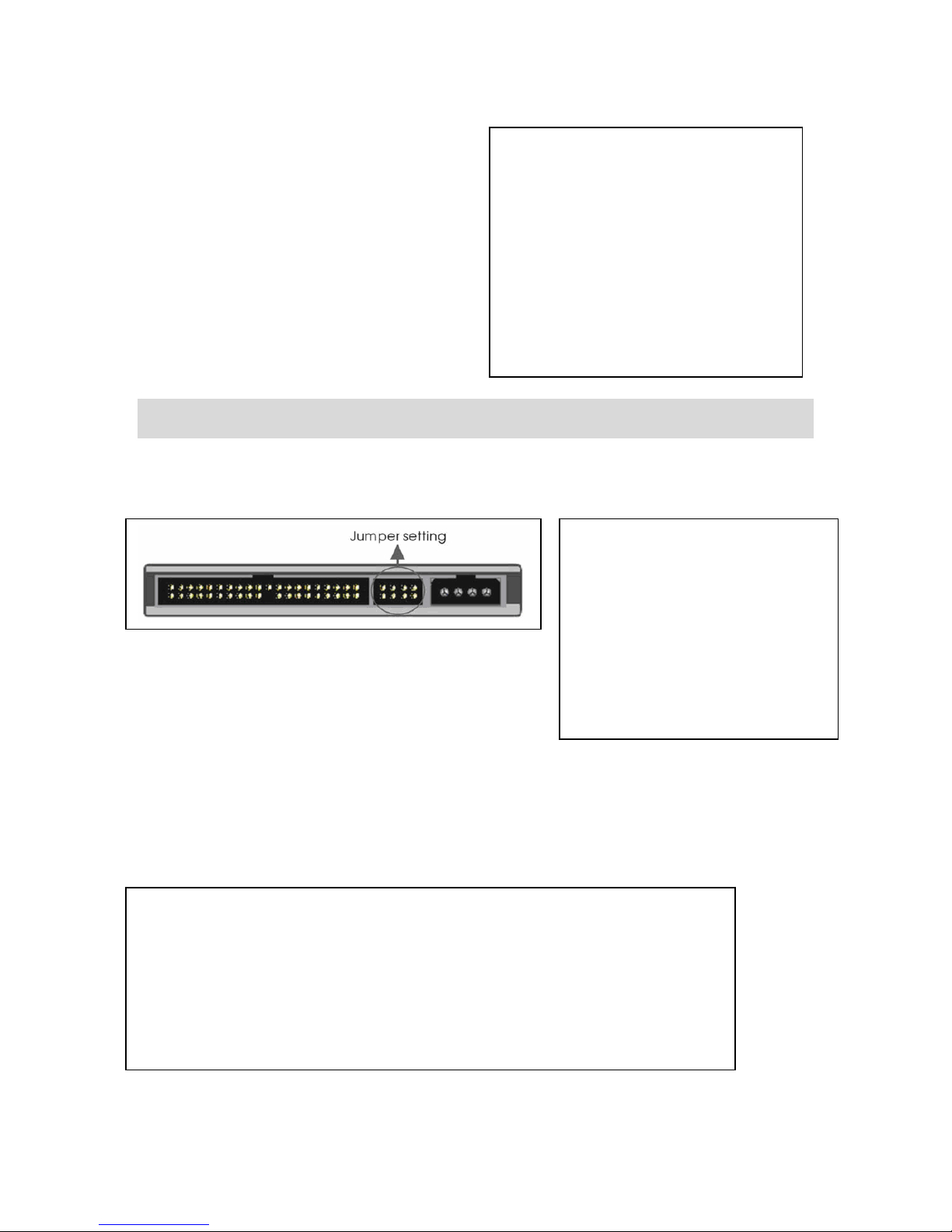
MICROPHONE SPEAKER INSTALLATION
AUDIO INPUT
• IN1~IN4: 4 audio inputs.
• MIC to the audio input (IN1~IN4) to record
audio.
.
Tip: Use Amplifier to obtain better sound recording
75
Page 76
• Connect a speaker to the audio output,
to have audio playback sound.
HDD INSTALLATION
Set HDD in MASTER mode if it is the only HDD in system. Set HDD in Slave mode if it is a
secondary HDD. Refer to the HDD manual for jumper settings.
One HDD installation
Insert the HDD shown in 1, and make sure the HDD is set to “MASTER”.
Two HDDs installation
Insert the first HDD shown in 1, (set up jumper as “MASTER”); insert the second HDD shown in 2
(set up jumper as “SLAVE”)
Caution: 1. Power off the DVR before HDD installation.
3. Suggested HDD brands to use: Maxtor or Hitachi, 7200 RPM (or above), ATA-100
Maxtor, Hitachi, and Seagate if firmware version is above V1.46.
*DVR Firmware version can be found in SYSTEM MENU>CONFIGURATION>
SYSTEM INFORMATION>S/W VERSION
4. HDD storage 400GB (or above) is supported.
5. Do not use Cable Select” option.
76
Page 77

OPERA TION
DISPLAY CONFIGURATION
Chapter
6
1. Time
• Current system time or the recorded time in playback
2. Date
• Current system date or the recorded date in playback
3. Camera title
• Camera title of the displayed channel. Camera title can be modified in
SYSTEM MENU>CONFIGURATION>CAMERA SETUP > CAMERA TITLE. .
77
Page 78
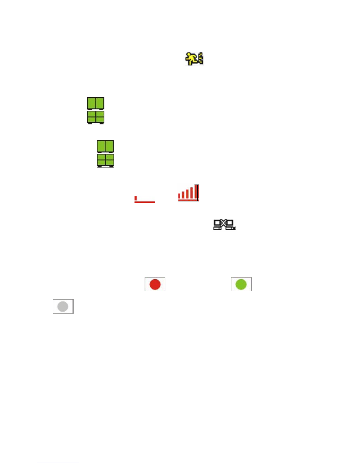
4. Record mode
• The current recording mode alarm motion continuous
5. Record resolution
• 4CH 50IPS@720X288/60IPS@720X240
• 4CH
• 4CH
• 8/16CH:
• 8/16CH:
• 8/16CH:
100IPS@360X288/120IPS@360X240
200IPS@360X144/480IPS@360X120
50IPS@720X288/60IPS@720X240
100IPS@360X288/120IPS@360X240
200IPS@360X144/480IPS@360X120
6. Quality
• To show record quality LOW ~ HYPER
7. Network LED
• To show if there is a client connected.. Disconnected Connected
8. HDD record/search percentage
• In LIVE mode, Recorded HDD Space.
• In Playback mode, Percentage of the data played.
9. Record status
• To show the record status Emergency record(Red) scheduled record
(Green)
Stop record (White)
10. Audio output channel
• Indicates the Audio output channel.
78
Page 79
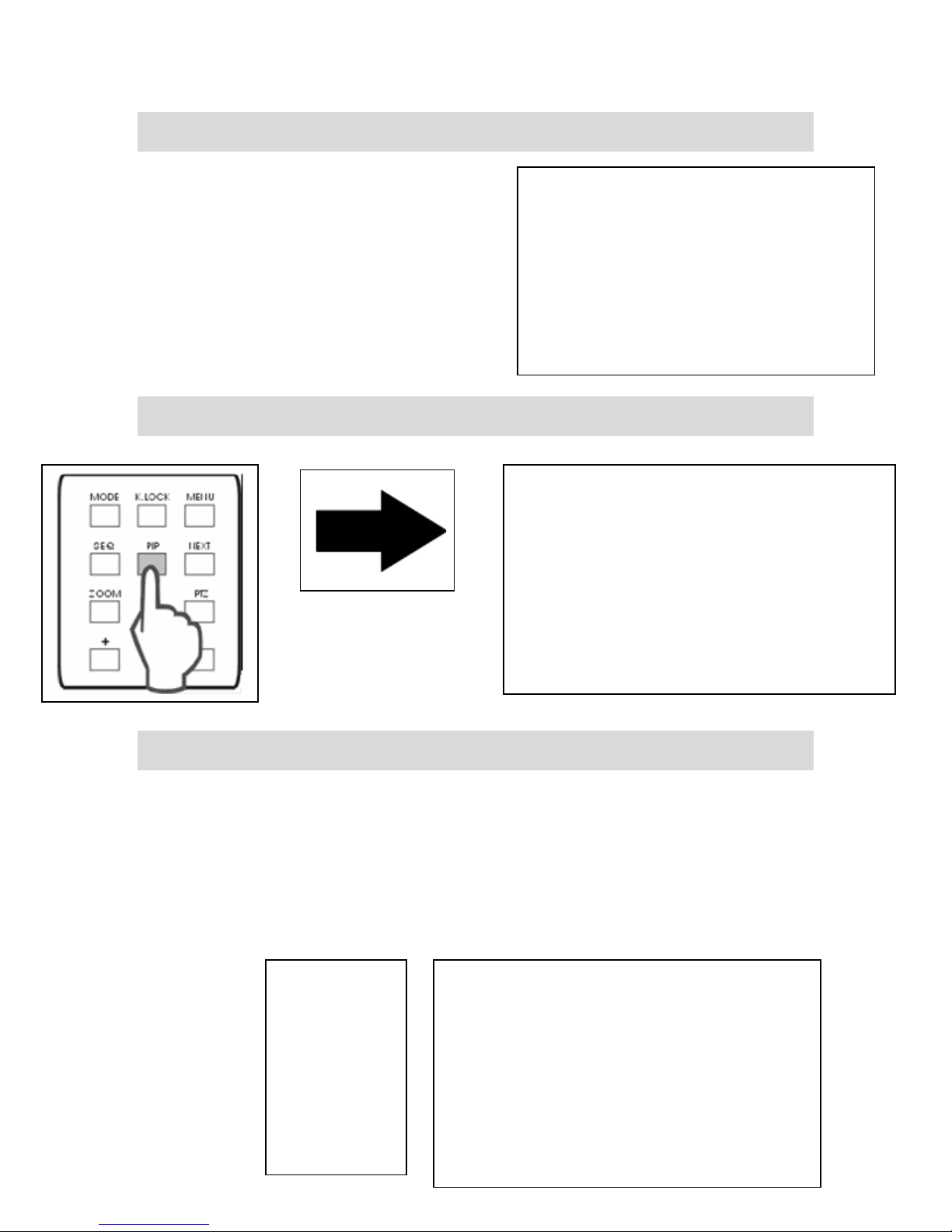
SCREEN SWITCH
• Press the number button to switch to the
corresponding channel for its full screen
view
• Mode: press to switch into different split
modes: 4/6/8/9/13/16 splits. Press +/-
button to adjust the order.
PIP VIEW
FREEZE VIEW
Freeze in split mode
• Split screen mode, press FREEZE and press a number button to select the
corresponding channel to freeze. Press the number again to cancel.
Freeze in Full mode
• In full screen mode, Press FREEZE to freeze the channel, and press FREEZE again to
cancel.
79
Page 80

VIEW IN SEQUENCE
• Sequence is only functional in full screen.
• Press SEQ for 2~3 seconds and enter sequence mode.
Press SEQ for 2~3 seconds again to cancel it.
• Sequence order A > B > C > D …>A > B …
• Sequence time is adjustable in system setup. Please see SYSTEM MENU>
CONFIGURATION> INTERVAL SETUP for details.
ZOOM VIEW
• Select channel zoom and press ZOOM to enlarge to 200%.
• Use the direction buttons to select area and press ENTER to zoom. Press ZOOM again
to cancel
80
Page 81

KEY-LOCK
• After pressing “K. LOCK “, LOCK status will appear and disable all front panel controls.
To unlock, press and hold K.LOCK and enter Admin password.
SWITCH AUDIO CHANNEL
• Press AUDIO you will see
the current audio output channel.
• Press AUDIO again for next audio channel and continue
to turn OFF.
. The number indicates
81
Page 82
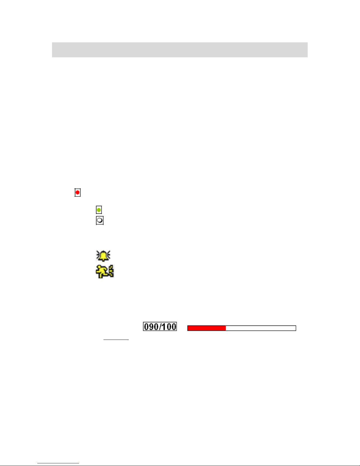
RECORD
• Emergency record (Red): press REC to start emergency record in continuous
record mode, best resolution and quality.
Schedule record (Green): record setup schedule.
o
o
Stop record (White): record schedule is set to “not record”.
• Record mode:
o Alarm record: records when alarm is triggered.
o
Motion record: records when motion is detected.
• Continuous record: records co ntinuously.
• When power is cut off, will automatically resume its recording schedule after power is
back.
• Record percentage: or
numeric or bar graph. Shows HDD storage available.
NOTE: Stops recording:
1. In Menu mode.
2. No video input.
3. Cameras are set to record off.
4. No motion is detected while in MOTION record mode.
5. Record schedule is set to “Not Record”.
6. In Search mode.
7. In Duplex Mode, stops recording when in Playback mode.
82
Page 83
PLAYBACK
Play/Stop
• Press “ PLAY ” key
on front panel to start
playback.
• Press“ PLAY ”during
playback to choose play forward or backward.
• Press“ STOP ”key to stop playback.
SWITCH AUDIO CHANNEL
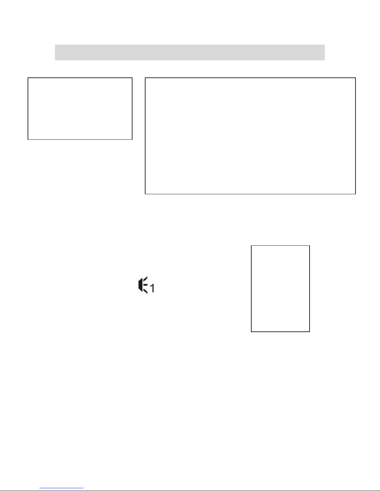
• Press “SEQ/AUDIO” to switch to other audio channels
o You will see
output channel
, the number represents audio
83
Page 84
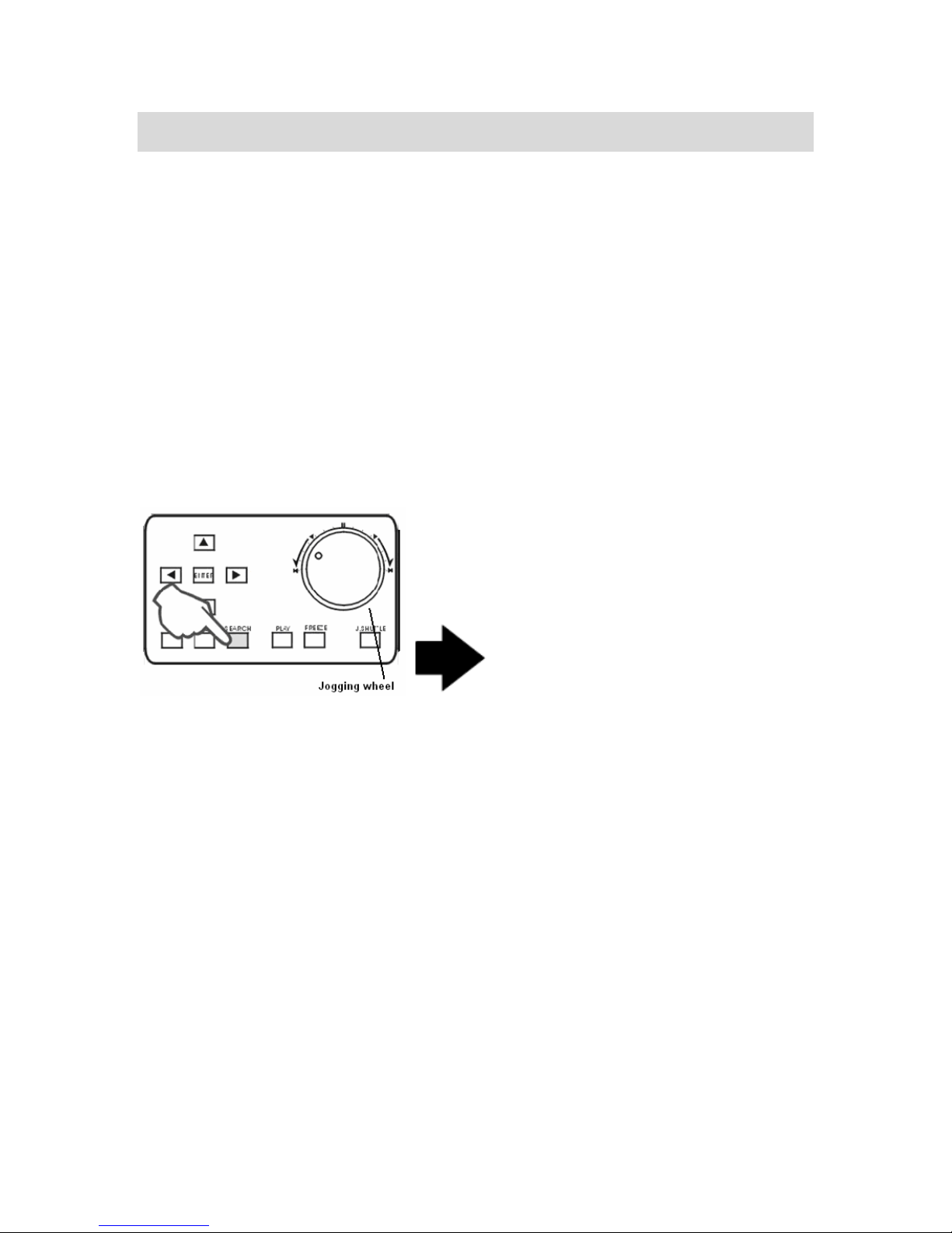
SEARCH MODE
Press SEARCH key to open the search dialog window. You will see 3 modes for search:
SEARCH BAR, TIME/DATE, and EVENT LIST.
1. SEARCH BAR
• Search by recording percentage. Using Jog-shuttle to change percentage value.
2. TIME/DATE
• Search by appointing a time and date
3. EVENT LIST
• Search by Event list.
SEARCH BAR
• Use Jog-shuttle or +/- keys to select the recording percentage of the search bar. Press
“ENTER” key to confirm and start the playback.
84
Page 85

TIME/DATE
1. START: the start time and date of recording
• Shows the start time and date of the recording data.
2. END: the end time and date of recording
• Shows the end time and date of the recording data.
3. INPUT DATE/TIME Input the appointed time and date to start playback.
• Select the time and date by +/- key to adjust numbers and by
position.
• Then press “Enter” to start playback.
key to adjust the cursor
EVENT LIST
• CH- shows the channel in which the event happened
EVENT- shows the type of events: Motion detection (MOT), Image lost (LOS), Alarm
trigger(ALM).
TIME/DATE- shows the event time and date.
• Keeps up to 1000 events in its EVENT LIST.
• Using key to select events and +/- key to change pages.
85
Page 86

Playback speed adjustments
• While playback, using the direction keys to adjust
the playback speed.
Speed up the playback
The range of speed adjustment: 1/16X~1X, 1X~64X
Slow down the playback.
Rewind
Play in forward direction.
• Press “J.SHUTTLE”key to pause the playback.
Press “J.SHUTTLE”again to continue the playback.
Adjust Playback speed by JOG-SHUTTLE
• While in playback, press “J.SHUTTLE”key to adjust the playback speed.
1. High speed playback/Low speed playback/Forward Playback/Rewind Playback.
• Using the outer circle of Jog-shuttle to adjust the playback speed. Turn clockwise for
forward direction, and turn counter-clockwise for Rewinding.
Playback step by step
• Using inner circle of Jog-shuttle. Turn clockwise for forward direction and turn counter-
clockwise for backward direction.
86
Page 87
Adjust Playback speed by IR remote controller
While playback, select the direction keys of remote control to adjust the speed.
X times high-speed playback. X times low speed playback.
Rewind. Play in forward direction.
Adjust speed using REW key (High-speed backward playback) or FF key
(High-speed forward Playback). Press the keys repeatedly to adjust the speed
rate.
Adjust speed using SLOW-Motion keys (Slow playback in backward or
forward mode). Press the keys repeatedly to adjust the speed rate.
Playback picture by picture using STEP keys (Step playback in backward or in
forward).
87
Page 88
Chapter
7
NETWORK AND CLIENT
SOFTWARE
Network Introduction
View video from your PC anywhere in the world by connecting your DVR LAN connection to your
network system.
Network installation and setup
1. Connect DVR LAN connection to your LAN router.
88
Page 89

Static IP address
2. Identify if you have Static IP or Dynamic
IP service. If you do not know, ask your
ISP (Internet Service Provider).
Note: Static “IP address is highly
recommended”, because of the video
connection reliability.
3. Make sure you have DirectX 9.0c or later on your computer. If not go to
www.microsoft.com/directx
Go into Search to see if DirectX file is on your computer. Just verify it is on your computer
and exit.
89
Page 90

4. Make sure that you have the following information:
A. IP address.
B. Subnet Mask.
C. Default Gateway.
D. If there is a DNS number.
E. Next verify your IP address (for your domain) by going to www.whatismyip.com.
is the IP address you will use to log in remotely.
5. Access your DVR network settings. Enter SYSTEM MENU > EXTERNAL DEVICE > TCP/IP
SETUP > IP CONFIG SETUP.
SYSTEM MENU
DISPLAY SETUP
RECORD SETUP
BACK-UP
>>EXTERNAL DEVICE
FACTORY DEFAULT
LANGUAGE
IP CONFIG SETUP
MAC ADDRESS XX-XX-XX-XX-XX-XX
IP ADDRESS XXX.XXX.XXX.XXX
IP PORT 08000
GATEWAY XXX.XXX.XXX.XXX
SUBNET MASK XXX.XXX.XXX.XXX
DHCP SETUP MANUAL
EXTERNAL DEVICE
>>TCP/IP
RS232C SETUP
PANTILT SETUP
AUDIO SETUP
TCP/IP SETUP
>>IP CONFIG SETUP
DDNS SETUP
CONNECTION SETUP
DHCP SETUP
This
90
Page 91

SYSTEM MENU > EXTERNAL DEVICE > TCP/IP SETUP > IP CONFIG SETUP.
6. Enter the IP address, gateway, subnet mask provided by your ISP. Then, assign a port
number to the DVR like 08000, or you can use the default one as well.
7. If you find that you cannot enter or change any addresses, check if DHCP is set to Automatic.
Press MENU to go back to the previous page, TCP/IP Setup, and then enter DHCP SETUP.
Select DHCP MODE and press ENTER to switch DHCP to MANUAL
8. In some very rare cases, we found the DVR did not support certain Static IP Addresses. If it
happens, add a Router to the network system. The setup is the same as the next session,
Via ADSL with Dynamic IP.
9. The Gateway IP is your router’s IP address and the Subnet Mask should match the Subnet
Mask IP of your router.
10. To connect to the world wide area network for remote viewing you must configure your
router to allow port forwarding. Super Circuits does not provide technical support for
router setup. Contact your service provider/router manufacturer for support on setting up port
forwarding. Ask them for help in forwarding your port number (should be 8000) in the IP
address of the DVR
11. Caution: It is strongly suggested to change the password after the initial setup. Please keep
records of your password. Change your Admin password from the factory default to
something you can remember like 1234 or admin.
91
Page 92
PASSWORD SETUP ADMIN
USER ID ________
NEW PW ________
CONFIRM ________
Enter NEW PW DO NOT HIT ENTER hit down arrow key to ENTER CONFIRM and reenter your
new password to confirm. Hit ENTER.
12. Tip: If you have other computers connected to the router, you can find out the Subnet Mask
and Gateway information from the computers. From the computer desktop’s Start Menu,
choose Run. Type "cmd" to open a command prompt. In this command prompt, type
“ipconfig” and hit "ENTER" and it’ll show the computer’s IP configuration. Your DVR should
have the same IP configuration for Subnet Mask and Gateway as the computer, if they are
connected to the same router. In addition, the first 3 segments of the local IP Address should
be the same as well. For example, if your computer’s local IP address is 192.168.1.100, your
DVR’s IP address should be 192.168.1.XXX. NOTE: Your DVR should have a dedicated IP
address provided by your IP provider or IT department.
13. Exit the setup menu. Turn DVR power off for ten seconds or more and restart the DVR. If
the DVR is connected to a router it is a good idea to recycle the power on it also.
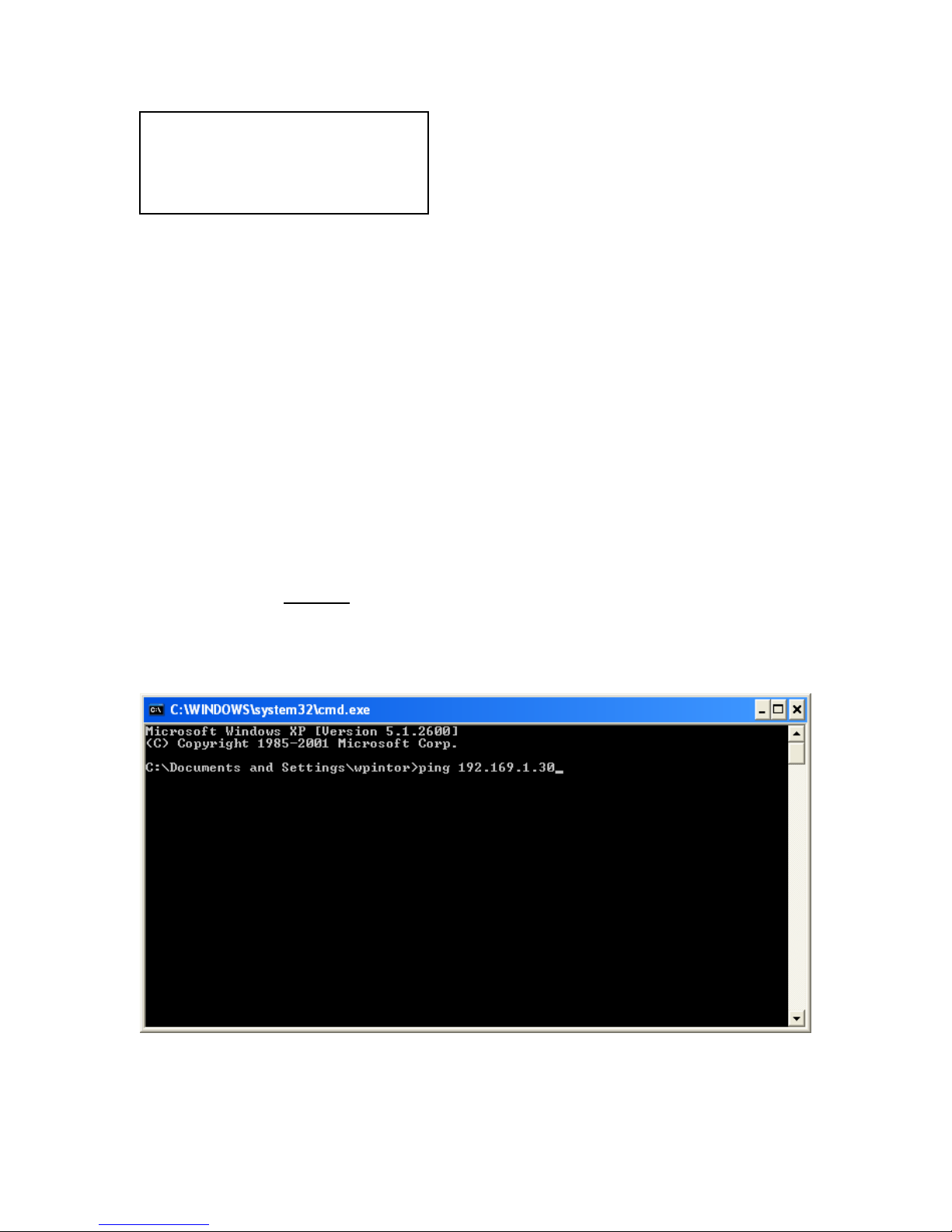
14. Return to the computer:
A. Select “Run”
1. Type “cmd” and click “OK”.
2. A black box
“ping” at the dos prompt, hit space bar and the IP address of the DVR and then click
“OK”.
Example below:
will pop up with a “C” prompt. After the “C” prompt type
NOTE: This is important and will come into play
when trying to access the DVR from your PC.
92
Page 93
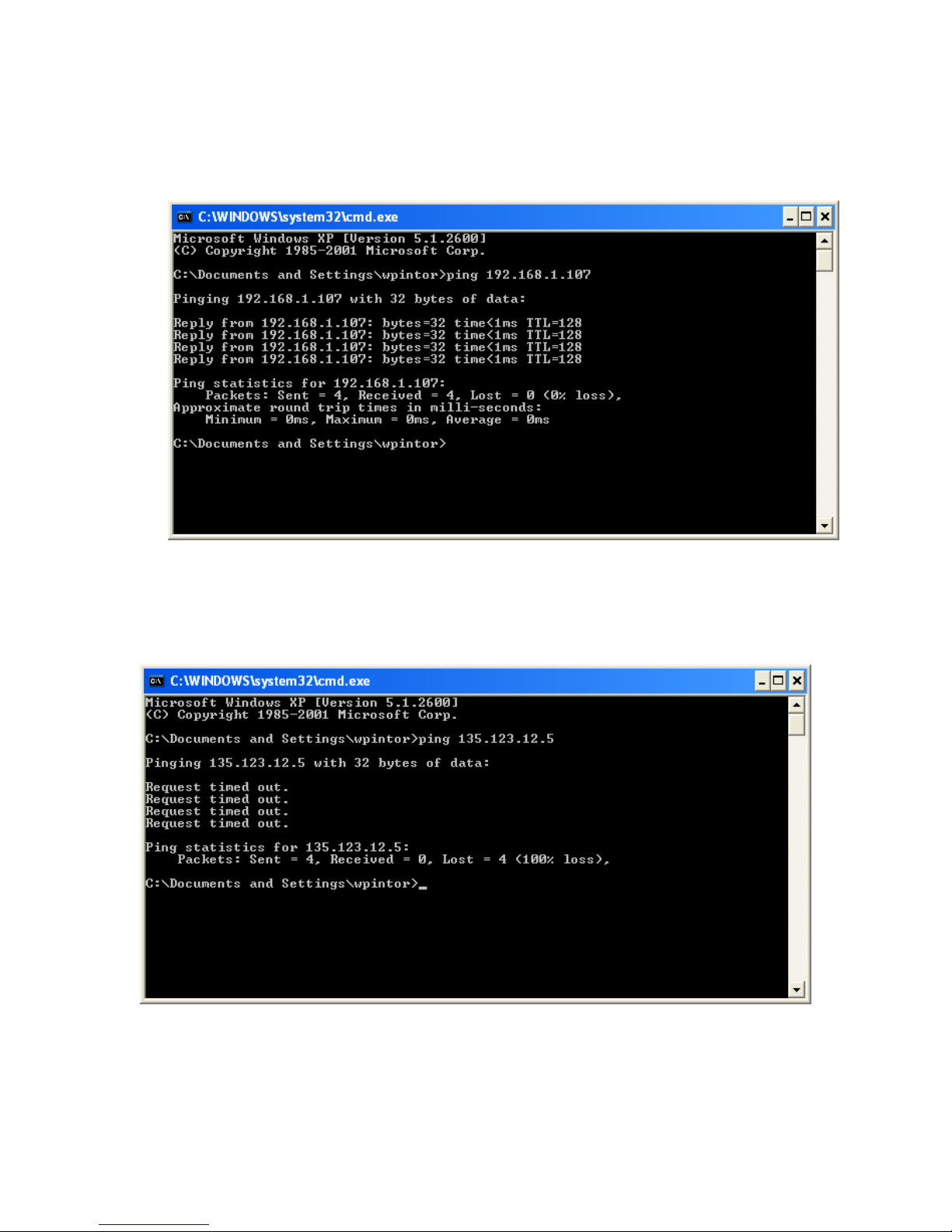
15. A box will pop up and it should say “reply from” the IP address 3 or 4 times. You will also see
Packets sent = 3 or 4, Received = 3 or 4 and Lost = 0. This will tell you that, you’ve
successfully connected to your DVR and we can proceed. Like FIG.1 below.
FIG.1
16. If you’re seeing Request timed out and Packets: Sent 3 or 4, Received = 0, Lost = 3 or 4 like
FIG.2 below, then you have not established a LAN connection between the DVR and the
computer.
FIG.2
93
Page 94
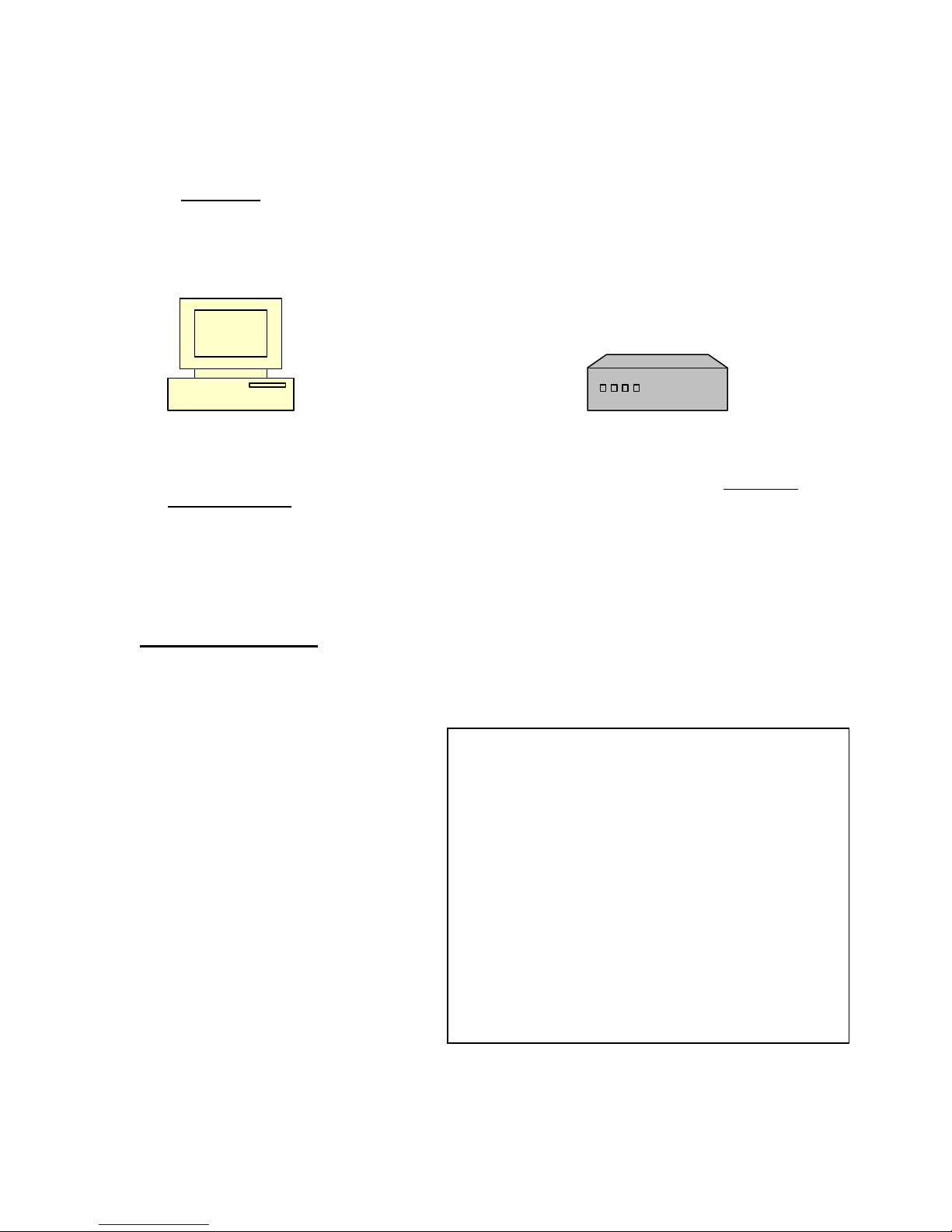
17. You will need to recheck all DVR network settings above, check with IP provider or IT
department, router settings, and make sure cables are good and connected. This could also
be due to a bad cable between the DVR and router or a bad DVR Network Interface
Controller (NIC). Check the Ethernet cable connection on the back of the DVR and check for
a green light
indicate that the DVR’s NIC is bad and call us for tech support. If green light is on, as a final
check, connect the DVR directly to the computer using an Ethernet crossover cable (which is
available at any electronics store such as Radio Shack, or Best Buy, Circuit City, etc…)
eliminating all other cables and equipment. And repeat the pinging process.
-----------------------------------------------------------------
PC Ethernet Crossover Cable DVR
18. If you’re looking at FIG.1 and this is the case then you have demonstrated that a Local Area
Connection (LAN) has been made between the DVR and the computer. Proceed to Software
installation.
and that it blinks when you “ping” the DVR. If it is not blinking, this could
INSTALLING NETWORK SOFTWARE
Client software
Install and setup
Insert the Install CD into PC CD-ROM,
and software will automatically Install
program. Recommend Windows XP or
Windows 2000.
1. Click Install Client software.
• Select a Destination Folder.
• When finished, the software will
create a shortcut on the desktop.
• Click the shortcut to run the client
software.
94
Page 95
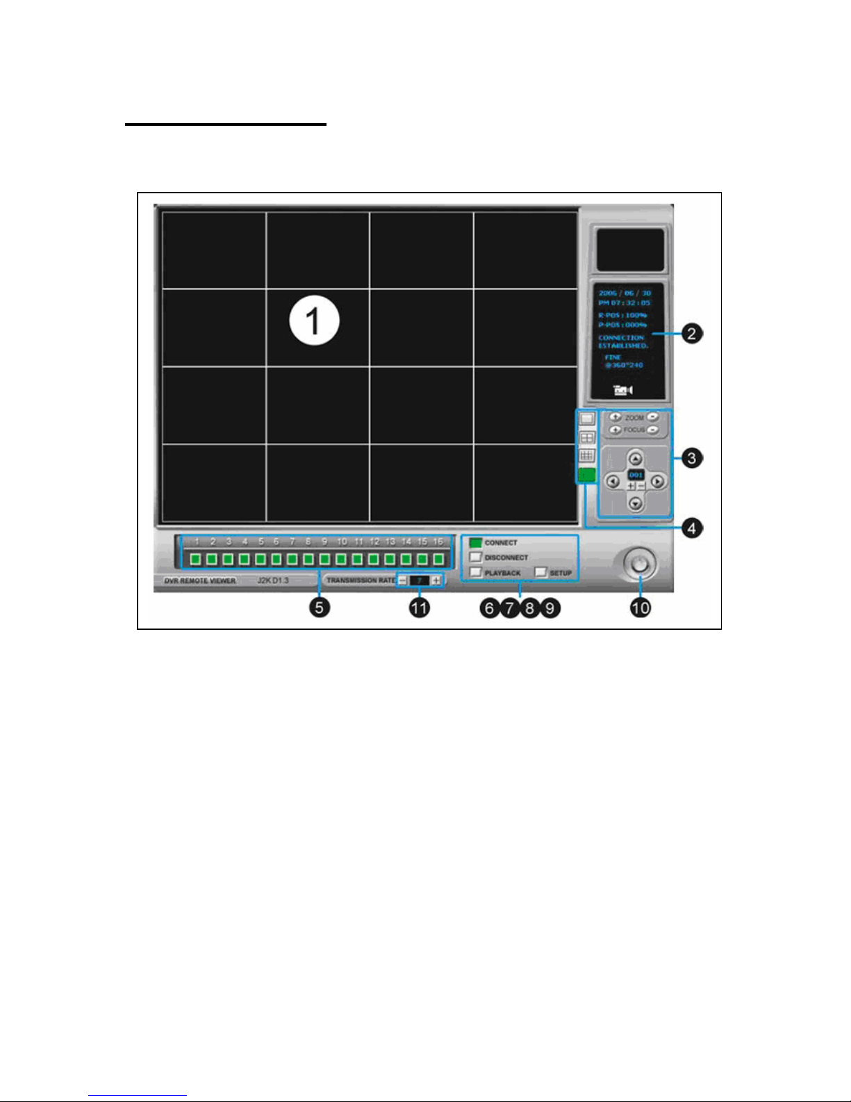
Software operation
Remote viewer interface
1. Live Display
Remote DVR Live display
2. Current Status
To show the current status
3. PTZ Camera Control
To control PTZ Camera
Zoom/Focus/Direction
※ Remote Control of PTZ
4. Screen Split
Select Full/4/9/16 split screen display
5. Channel Selection
Select CAM1~16 in full or split screen display
6. Connect
Select DVR IP address from IP list for connection.
95
Page 96

7. Disconnect
Disconnect the DVR
8. Playback
Enter playback
9. Setup
Enter the setup
10. Power
Close the remote program.
11. Transmission Rate
Adjust transmission speed, range 1~10. You will lose Image quality when increasing
transmission speed.
NOTE: Two users can access remote video.
Client software setup
IP/PORT
1. DVR NAME
• Enter DVR’s location or name
2. IP LIST
• Show list of saved DVR IP addresses.
3. IP ADDRESS
• Enter DVR IP address
4. PORT
• Enter DVR’s port number.
5. USER ID
• Enter the user ID as ADMIN.
6. PASSWORD
• Enter DVR Admin’s password
7. MANUAL/DDNS
• If you have static IP address or are not using DDNS service, select MANUAL. If you are
using DDNS service, select DDNS and click the tab DDNS on the top and enter DDNS
setup page.
※ If your setting up a new DVR, follow the steps:
1. Enter the DVR’s location or name.
96
Page 97
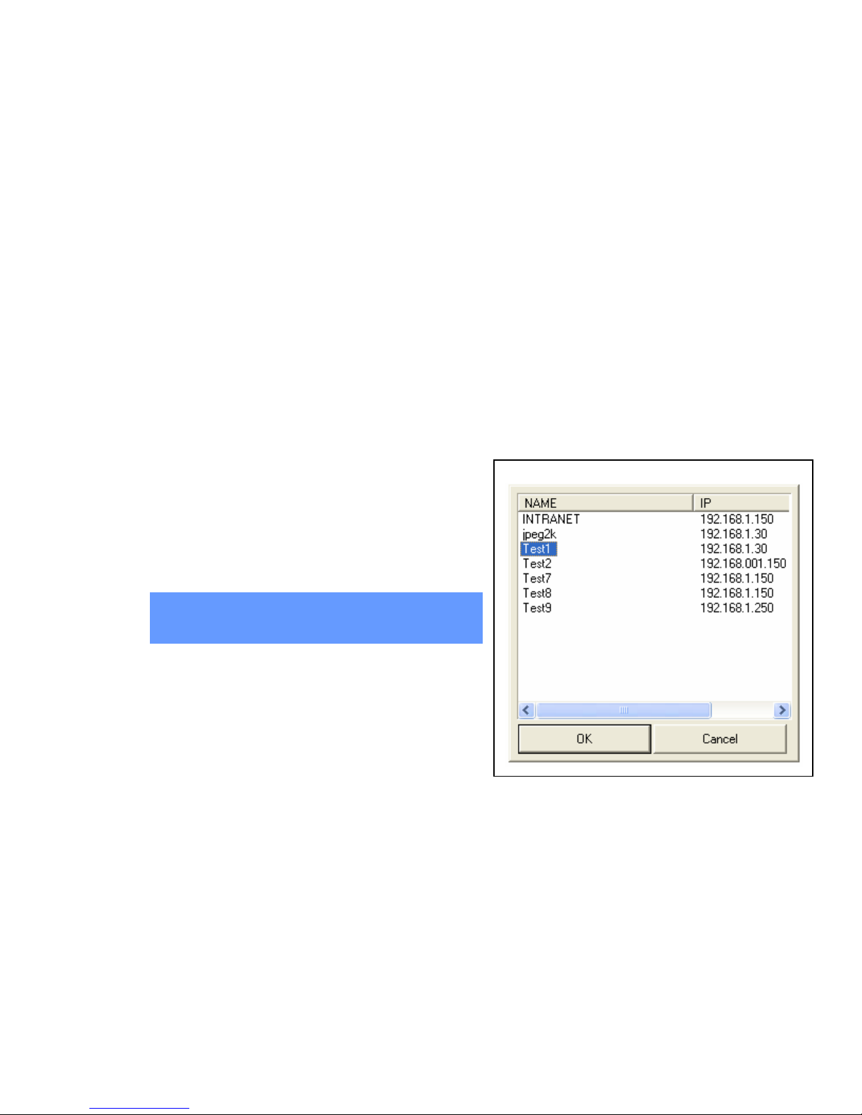
2. Enter the DVR’s IP address and port number.
3. Enter the user ID as ADMIN and ADMIN password. The ADMIN password used here needs
to be the same as the ADMIN password used in your DVR or the password you use to enter
the DVR MENU. Password cannot be blank or (________). If you have not changed your
password from blank or (________) on your DVR, do so at this time. Change your DVR
Admin password.
4. Press SAVE and OK. The name of the DVR must be highlighted before clicking on OK or the
DVR will not connect. Click CONNECT from Remote Viewer Interface.
Click “CONNECT”.
NOTE: Highlight the IP address and click on
OK.
97
Page 98

PTZ/SAVE
1. Circular Monitoring Interval
• Set up sequential switch interval.
2. Scan Rate
• Select Fast forward (FF) speed for
remote Playback.
2. PTZ Type
• Select PTZ protocol.
4. PTZ Baudrate
• Select PTZ baud rate.
5. Set Path to Save Recorded Images
Set path to save video clip.
6. Run in Full Screen Mode
Check box for full screen mode.
Remote Viewer Setup
1. Screen Division
• Split mode.
2. Network Speed value
• To set up the transmission rate
for split screens as default value.
PTZ control
1. ZOOM
• Use + / - to adjust PTZ Zoom.
2. FOCUS
• Use + / - to adjust PTZ Focus.
3. PAN/TILT CONTROL
• Click the direction buttons to control Pan/ Tilt.
4. PTZ ID
• Show the PTZ ID.
5. [+/-]
• Click +/- to select a PTZ ID.
98
Page 99
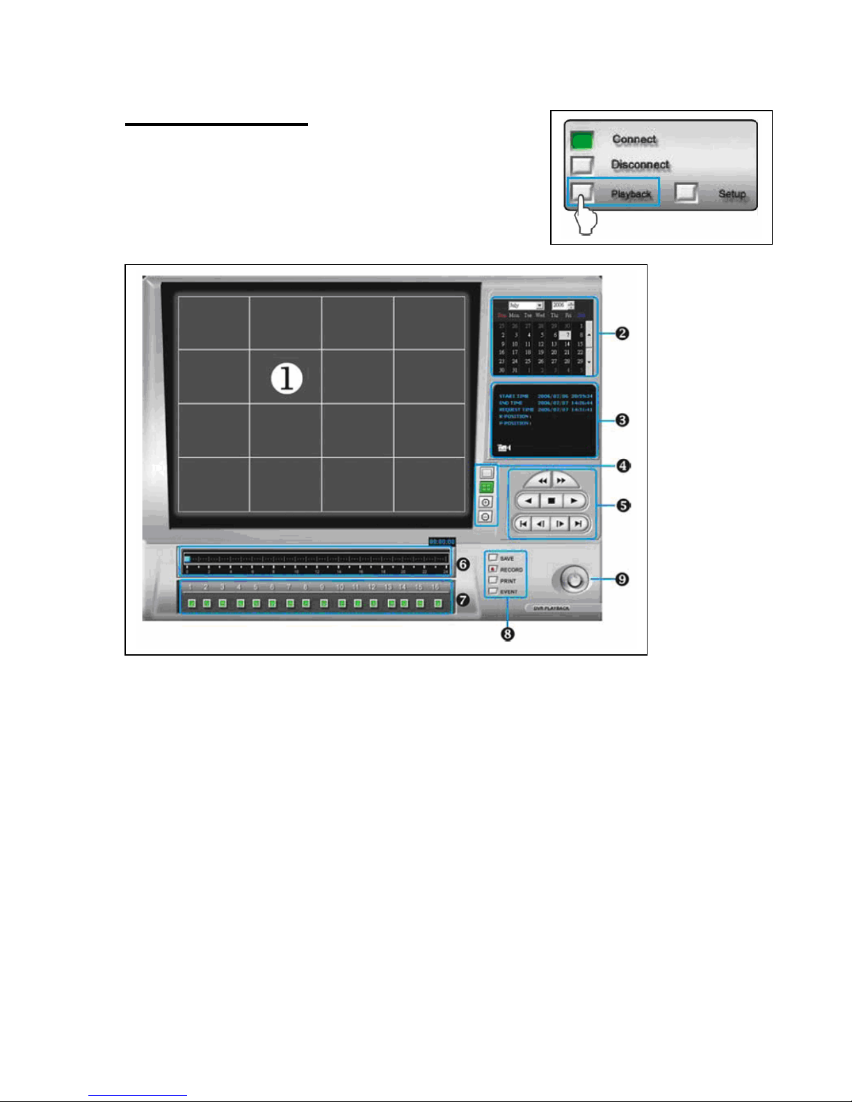
Remote playback
• When the DVR is connected, click PLAYBACK to enter
Playback interface.
Remote Playback Interface
1. Playback Picture
• Show the playback video
2. Time/Date Selection
• Select time/date of playback
3. Record and Playback Status
• START – To show the record START Time/Date
• END – To show the record END Time/Date
• REQUEST – To show the record DISPLAY Time/Date
4. Screen Split
• Select Full/4 split screen display
5. Search Button
• Operate the search function
6. Time Selection
• Select the time of playback
7. Channel Selection
• Select CAM1~16 when full screen display
99
Page 100

8. Auxiliary Function Button
• SAVE : Save image as JPEG file when the playback is paused.
• PRINT : Print picture when playback is paused.
• EVENT : To show the event list.
• RECORD : Record image in AVI format.
9. Power
• Turn off playback and return to Remote Viewer.
Search button
1. Fast Reward (RW)
2. Fast Forward (FF)
3. RW (Speed 1X)
4. Stop / Pause
5. Playback (Speed 1X)
6. Start at the beginning of recording
7. Jump to the previous hour
8. Jump to the next hour
9. Go to the end of recording
Remote Playback Operation
• Drag the mouse over the time bar to select a playback time.
• Select a Year/Month/Day to playback.
• Click RW or PLAYBACK to start the playback
• If the DVR cannot find the selected playback date and time,
the playback starts from the next video clip.
100
 Loading...