

Super Circuits DVQ-2, DMR 4 RT, DMR 16 RT, DMR 8 RT User Manual

DVQ-2
USER MANUAL

SUPER/CIRCUITS
11000 NORTH MOPAC EXPRESSWAY
SUITE 300
Austin, TX 78759
Phone 800-335-9777 • Fax 866-2567-9777
2

Please read instructions thoroughly before operation and retain it for future reference.
The lightning fl ash with arrowhead symbol, within an equilateral triangle, is intended to alert the user to the presence of
uninsulated “dangerous voltage” within the product’s enclosure that may be of suffi cient magnitude to constitute a risk of
electric shock to persons.
CAUTION:
To reduce the risk of electric shock, do not expose this apparatus to rain or moisture. Only operate this apparatus from
the type of power source indicated on the label. The company shall not be liable for any damages arising out of any improper use, even if we have been advised of the possibility of such damages.
This apparatus is manufactured to comply with the radio interference requirements.
Disclaimer We reserve the right to revise or remove any content in this manual at any time. We do not warrant or assume any legal liability or responsibility for the accuracy, completeness. The content of this manual is subject to change
without notice.
THIS PRODUCT IS LICENSED UNDER THE MPEG-4 VISUAL PATENT PORTFOLIO LICENSE FOR THE PERSONAL
AND NON-COMMERCIAL USE OF A CONSUMER FOR (i) ENCODING VIDEO IN COMPLIANCE WITH THE MPEG-4
VISUAL STANDARD (“MPEG-4 VIDEO”) AND/OR (ii) DECODING MPEG-4 VIDEO THAT WAS ENCODED BY A CONSUMER ENGAGED IN A PERSONAL AND NON-COMMERCIAL ACTIVITY AND/OR WAS OBTAINED FROM A VIDEO
PROVIDER LICENSED BY MPEG LA TO PROVIDE MPEG-4 VIDEO. NO LICENSE IS GRANTED OR SHALL BE
IMPLIED FOR ANY OTHER USE. ADDITIONAL INFORMATION INCLUDING THAT RELATING TO PROMOTIONAL INTERNAL AND COMMERCIAL USES AND LICENSING MAY BE OBTAINED FROM MPEG LA, LLC. SEE HTTP://WWW.
MPEGLA.COM.
3

TABLE OF CONTENTS
Warning..................................................................................................................................................3
1. OVERVIEW ......................................................................................................................................6
1.1 General Information ...................................................................................................................6
1.2 Features......................................................................................................................................6
1.3 Package Contents.......................................................................................................................7
2. FRONT AND REAR PANELS ..........................................................................................................8
2.1 Front Panels................................................................................................................................8
2.2 Rear Panels ...............................................................................................................................11
3. INSTALLATION GUIDE ................................................................................................................. 12
3.1 Camera and Monitor Installation.................................................................................................12
3.2 System Confi guration .................................................................................................................14
4. GETTING STARTED .......................................................................................................................15
4.1 Introduction................................................................................................................................15
4.2 Reconfi gure your DVR ...............................................................................................................16
a. Basic Menu Setup...................................................................................................................16
4.3 Reset to factory Default .............................................................................................................17
4.4 Clear HDD (Hard Drive).............................................................................................................17
4.5 Date/ Time..................................................................................................................................18
4.6 Overwrite....................................................................................................................................18
4.7 Motion Detection........................................................................................................................19
4.8 Record Quality and IPS (Images Per Second)...........................................................................20
5. MENU CONFIGURATION.................................................................................................................22
5.1 Menu Introduction .....................................................................................................................22
5.2 Record .......................................................................................................................... ............22
5.3 Timer .........................................................................................................................................23
5.4 Date...........................................................................................................................................24
5.5 Advance.....................................................................................................................................24
5.6 Camera.......................................................................................................................................25
5.7 Motion Detection.........................................................................................................................25
5.7.2 Detection Timer..................................................................................................................28
5.8 Display........................................................................................................................................28
5.9 Alert............................................................................................................................................29
5.10 Remote.....................................................................................................................................30
5.11 System......................................................................................................................................31
5.12 Network....................................................................................................................................32
5.13 Backup.....................................................................................................................................32
5.14 HDD info...................................................................................................................................33
5.15 Event Log.................................................................................................................................33
5.16 Search......................................................................................................................................34
6. ADDITIONAL OPERATIONS............................................................................................................35
6.1 Key Lock and Unlock.................................................................................................................35
6.2 Switch NTSC/ PAL System.........................................................................................................35
6.3 Upgrade.....................................................................................................................................35
6.4 Audio Backup and Playback.......................................................................................................36
6.5 PTZ Camera Setup and Control.................................................................................................37
6.6 R.E.T.R Setup.............................................................................................................................37
4

7.0 NETWORKING...............................................................................................................................38
7.1 Things to do before networking your DVR...............................................................................38
7.2 Tes t your connection................................................................................................................41
7.3 Software Installation.................................................................................................................43
7.4 Installation................................................................................................................................43
7.5 Remote Video Server Login Panel...........................................................................................44
7.6 Control Panel...........................................................................................................................45
7.7 System Confi g..........................................................................................................................47
7.8 Network....................................................................................................................................47
7.9 DVR..........................................................................................................................................49
7.10 Detection................................................................................................................................49
7.11 Network Backup (Cool Feature).............................................................................................50
7.12 Video Backup Player..............................................................................................................51
7.13 Search List.............................................................................................................................52
7.14 Timer Record..........................................................................................................................53
7.15 Date........................................................................................................................................54
7.16 Record Setting.......................................................................................................................54
7.17 Alarm......................................................................................................................................55
7.18 General..................................................................................................................................55
7.19 Account..................................................................................................................................56
7.20 Online User Info.....................................................................................................................56
7.21 File Path.................................................................................................................................56
7.22 Operation via IE Browser.......................................................................................................57
8.0 REMOTE PTZ Camera Control Panel...........................................................................................58
9.0 FAQ/ TROUBLESHOOTING..........................................................................................................59
9.1 Default Value............................................................................................................................60
APPENDIX 1 INSTALL HDD.................................................................................................................60
APPENDIX 2 PIN CONFIGURATION....................................................................................................61
APPENDIX 3 RS-232 PROTOCOL.......................................................................................................62
APPENDIX 4 RECORDING TIME TABLE.............................................................................................63
APPENDIX 5 COMPATIBLE USB FLASH DRIVE BRAND..................................................................64
APPENDIX 6 COMPATIBLE HDD BRAND ..........................................................................................64
APPENDIX 7 MENU TREE....................................................................................................................65
5

1. OVERVIEW
1.1 General Information
• Video Compression Frame: MJPEG ;
• Format CIF: MPEG4
• USB Interface NO
• Backup Device Network remote backup
• IR Transmitter NO
• Audio I/O 1 audio input, 1 audio output (Mono)
• R.E.T.R. (Remote EventTrigger Recording) NO
• Dimension 375mm (W) × 61mm (H) × 281mm (D)
• Support multi-language OSD
• System auto recovery.
• Supports PTZ cameras using RS-485.
• Support daylight savings.
• Supports manual / timer / motion / alarm / network remote recording.
• Ensure the authentication of recorded images with Watermark.
• Supports TCP/IP, PPPoE, DHCP and DDNS network connection
1.2 Features
MPEG4 DVR Technology
• Compression format providing crystal clear images with real time performance
Multiplex Operation
• Allow live display, record, playback, backup, and network operations at the same time
Free Upgrade to Advanced Functions
• Allow you to upgrade DVR functions without any charges
Long-Recording Hours
• 500GB can record more than 5 days. (4CH, Frame Best Quality, 30IPS)
Backup Function
• Supports network remote recording & backup
Remote Surveillance
• Supports remote surveillance of up to 5 users simultaneously with licensed software AP and IE browser
Intelligent Motion Trigger Recording
• With advanced motion detection like scheduled motion detection recording, 4 different adjustable motion detection
sensitivity options and quick search, you can customize your security system to meet your needs.
• Send e-mails or address FTP sites with image alerts when DVR Alarms trigger recordings.
• Support pre-alarm recording (8MB)
Covert Recording
• Mask live images with a blank screen displaying on your monitor, and still record.
A/V Support
• Supports 1 audio-in, 1 audio-out.
6
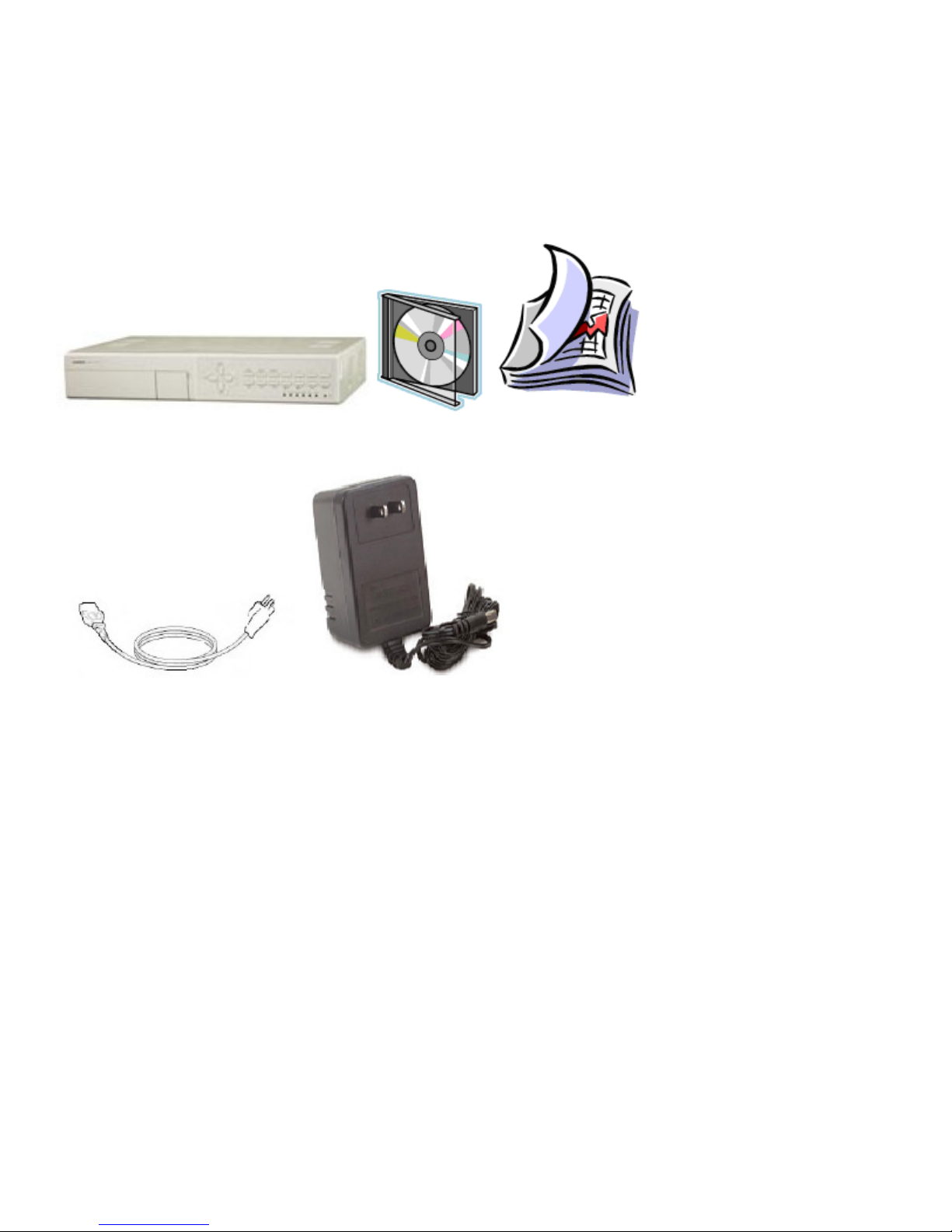
1.3 Package Contents
• DVQ unit × 1
• Power Supply × 1
• Power Cable × 1
• Manual × 1
• Software CD-R × 1
DVR-1 CD Manual
Power cord Power Supply
* Specifi cations are subject to change without notice.
7
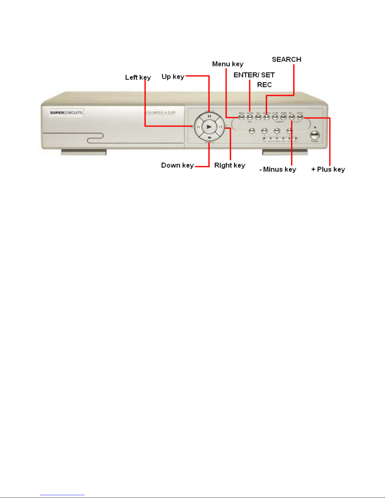
2. FRONT AND REAR PANELS
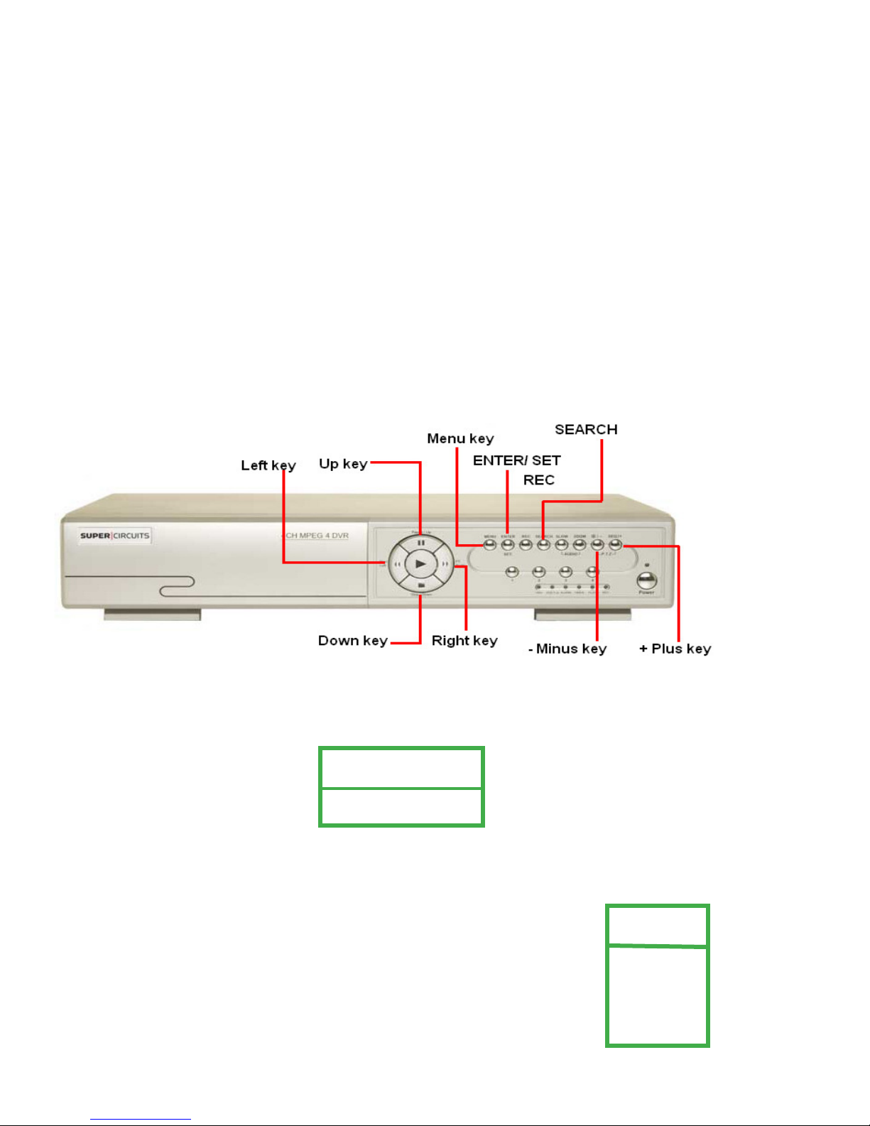
2.1 Front Panels
1) LED Indicators
The following LEDs will be on when:
• HDD (Hard Drive): HDD is reading or recording
• HDD Full: HDD is full.
• ALARM: Once the alarm is triggered
• TIMER: When timer recording is turned on
• PLAY: Under playing status
• REC: Under recording status
2) MENU
Press “MENU” button to enter the main menu.
3) ENTER / SET
• Press “ENTER” button to confi rm the setting.
• Press “SET” to change the position of the channel display.
• Press up/down/left/right direction buttons to select the channel that you want to change.
• Press “+“ or “-“ to select the channel you would like to display.
• Channel Display Position
Under the live mode, you can switch the positions of two channels by:
• Step1: Press “Set” to highlight one channel.
• Step2: Press “UP“, “DOWN”, “LEFT”, “RIGHT” button to change the channel position.
• Step3: Press “+” or “-” to select the channel.
• Step4: Press “ENTER” button to confi rm the setting.
Under the playback mode, you can select a channel to display in live video:
• Step1: Press “Set” to highlight one channel.
• Step2: Press “UP“, “DOWN”, “LEFT”, “RIGHT” button to select the channel you want to view.
• Step3: Press “+” or “-” to select the channel.
• Step4: Press “ENTER” button to confi rm the setting.
4) SEARCH
Press “SEARCH” button to enter the search menu.
5) SLOW
Under the playback mode, press “SLOW” button to decrease (1/2X) speed playback.
6) ZOOM
Press “ZOOM” button to enlarge the picture area.
8
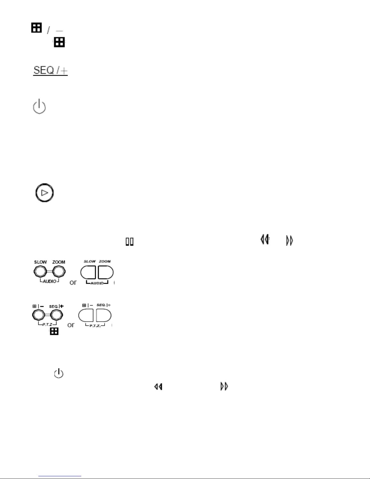
7)
Press “ ” button to display the 4 channels.
Press “-” button to change the setting in the menu.
8)
Press “SEQ” button to activate the call monitor, and press again to quit.
Press ”+” button to change the setting in the menu.
9)
Press POWER button for 1 to 3 seconds to turn the DVR on or off.
Note: Stop recording before turning off the DVR.
10) “CH1” “CH2” “CH3” “CH4”
Press one of the buttons to select the channel to display.
11) REC
Press “REC” button to turn on manual recording.
12)
Press Play to play recorded video. See page 10 for more details on PLAY BACK.
13) UP / PAUSE, DOWN / STOP, LEFT / REWIND, RIGHT / FORWARD,
Press one of the direction buttons to move the cursor up/down/left/right.
Under the playback mode: Press “ ” or “ ” button to pause / stop playback. Press “ ” or “ ” button
to fast rewind / forward.
14)
Press SLOW and ZOOM buttons at the same time to select live or playback sound for audio channels.
or POWER
or PLAY
(Audio)
15)
Press /- minus and SEQ /+ plus buttons at the same time to enter / exit the PTZ control.
In the PTZ control mode → Zoom in: Press “+” button ; Zoom out: Press “-” button
Adjust PTZ angle: Press direction buttons to turn up/down/left/right
16) Switch NTSC / PAL System
Press “
After shutting down the DVR, press and hold
the power button again to reboot the DVR (press until the monitor shows video images).
Note: The DVR will automatically detect PAL/NTSC system or manually switch
between PAL and NTSC systems.
17) Key Lock
Press “MENU” + “ENTER” on the DVR front panel at the same time to lock keys and to log in.
” or “POWER” button on the DVR front panel to shutdown the DVR.
(PTZ)
(switch to NTSC) or (switch to PAL) fi rst, then press
9

2.1.2 Playback
Press “ ” or “PLAY” button on the front panel, and the device will display the last recorded video.
Note: For playback to work properly the DVR needs to record a minimum of 8192 video frames.
Playback related operations are described below:
• Fast Forward
In playback you can increase fast forward and rewind speed by:
Pressing “
Press “
• Pause ( ) / Image Jog
Press “ “ button to pause the video playback.
In the Pause mode:
Press “
Press “
• Stop (
Pressing the “ ” stop button will return to live mode.
• Channel Display Mode
Display mode:
Press “
Full screen view:
Press the number buttons (1-4) to display the selected channel.
“ Right button once to get one frame forward.
)
/ Fast Rewind
“ once to get 4X speed forward and press twice to get 8X speed, etc. Maximum speed is 32X.
“ once to get 4X speed rewind and press twice to get 8X speed, etc. Maximum speed is 32X.
“ Left button once to get one frame rewind.
” button to display 4 channels.
Note: Under the playback mode, you can select a channel to display live video. For details, please refer to
“Position of Channel Display” on page 8.
• Slow Playback
Press “SLOW” button to reduce playback to 1/2X.
• Audio
Press
AUDIO 1 (L) – 1st audio channel, live audio;
AUDIO 1 (P) – 1st audio channel, playback audio
Connect audio camera to INPUT 1 on the DVR rear panel.
SLOW ZOOM buttons at the same time to play live (L) or playback (P) sound.
10

2.2 Rear Panel
1) 75Ω / HI-IMPEDANCE
When using LOOP, switch to HI-IMPEDANCE. When not using LOOP switch to 75Ω.
2) LOOP / INPUT (For channel 1~4)
LOOP Video output connector. INPUT: Connect to video sources.
Note: For video and audio applications, use inputs 1 or 2 with a audio camera.
3) MONITOR
Connect to MAIN monitor.
4) CALL
Use CALL monitor to view alarm triggered channel sequence.
5) Audio IN
Connect to audio sources. Use in conjunction with video channel 1.
6) Audio OUT
Connect to a monitor or speaker with 1 mono audio output.
7) USB
fi le backup.
Note: For the list of compatible USB fl ash drives, refer to “APPENDIX 5 COMPATIBLE USB FLASH DRIVE” Page 63.
8) D/V Port (Digital Video Port) NOT USED.
9) IR
Connect the IR receiver for remote control.
10) EXTERNAL I/O
Use the 15PIN DSUB to connect external devices (external alarm, PTZ camera, etc).
For detailed I/O port PIN confi guration, please refer to “APPENDIX 2 PIN CONFIGURATION”. Page 60.
11) LAN
Connect to LAN port.
12) LINK ACT.
LINK ACT LED will light when you have an internet connection.
13) DC 19V
Connect to power supply.
11

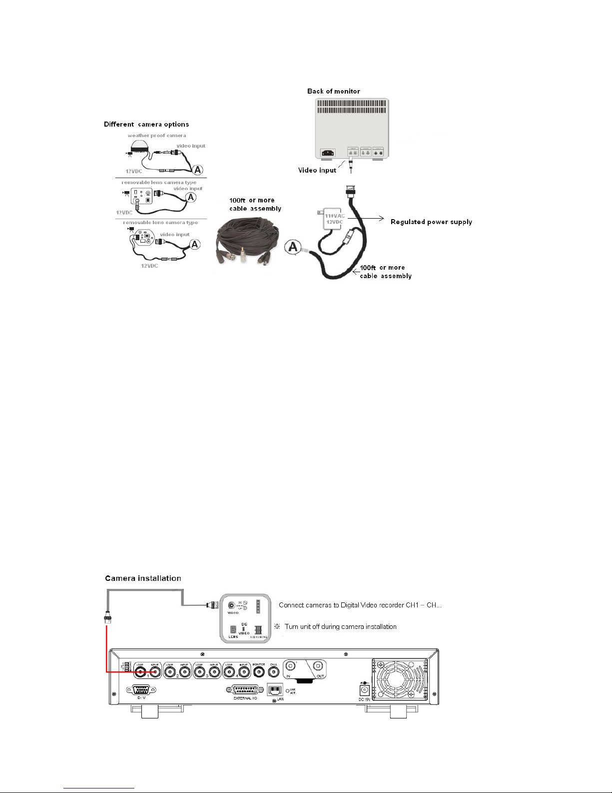
3.0 Installation Guide
3.1 Camera and Monitor Installation
This manual has been carefully written to help you assemble and confi gure your digital video recorder system for optimal
performance. It’s easy to setup your digital video recorder just follow the instructions on the following pages. If you have
any comments questions about this manual, please feel free to call us at 800-335-9777.
1. Remove your monitor from the box for testing your cameras and cables. You can use a TV set with a video input if you
don’t have a monitor. Plug your monitor into a 110-120 AC power source. Do not mistake the antenna input on the TV
for a VIDEO INPUT. Monitors and TV’s have video inputs clearly marked. The TV RCA input will look some what like
the image below (labeled VIDEO INPUT). This type of input connector is called an RCA female input jack.
RCA Female Jack
2. Remove your cameras and camera power supplies from the box.
3. Connect each one of your cameras to your power supply and cable assembly. Most cable assemblies are 100 ft long
or more.
12
4. Tes t each component of your video system prior to installation. Connect each camera directly to the video monitor,
using a new power adapter and cable for each camera. This will test each component of your video system prior to
installation.
If you get a bad picture while testing your camera, it could be a bad monitor, camera or the cable. It’s real easy to fi gure
out what’s causing the malfunction by just simply troubleshooting.
NOTE:
• Make sure you are using the proper power supply for your camera and that the cable connections are connected.
• Some cameras like our PC33 and 153 require a 24V AC power source and will not work properly with a 12V DC power
source.
• Do not use AC power supplies with Supercircuits EXT series cables such as EXT25, EXT50 or EXT100. Use the CAB BNC-25, CAN-BNC-50 or CAB-BNC-100 with AC power supplies.”
Grab another camera and replace it with a 2nd camera. If you have a good picture with the 2nd camera, the fi rst camera
is not working properly. Call SuperCircuits technical support to replace the camera. If the 2nd camera is not working
either, this could be a bad cable and we need to replace the cable with another cable. If you continue to get a bad display
or picture, we need to look at the monitor as the source of the problem. We can use another monitor or TV with a video
input to test our cameras and cables. After testing all components you are ready to do your fi nal installation. After testing
move on to the DVR installation.
5. Connect your cameras and monitor to the DVR.
DVR and Camera Installation
13

DVR and Monitor Installation
3.2 SYSTEM CONFIGURATION
14

4.0 GETTING STARTED
4.1 INTRODUCTION
This digital video recorder is designed to function right out of the box. We made setting up your DVR easier by adjusting
the time, date and record settings for you. Your DVR is set to record for 14 days with the video quality and frame rate set
to the highest settings.
IConnect the AC Power Cord with Power Adapter and plug into an electrical AC outlet. Turn your DVR on by hitting the
power button on the front panel. It will take approximately 5 to 15 seconds for the system to completely fi nish initializing.
Caution: Only use 100~240VAC 50~60HZ / 19VDC 2.21A or 3A power supply. Use only SuperCircuits power supplies.
If your digital video recorder is not working properly:
• Not showing any video.
• HDD (Hard drive) error messages.
• HDD not found.
• All video camera images are distorted.
• DVR will not record.
• DVR is not showing proper date & time.
See Reconfi gure Your DVR section in this manual page 16.
If your DVR is running fi ne but you want to custom confi gure your DVR, Please see DVR MENU confi guration in this
manual page 21.
15
4.2 RECONFIGURE YOUR DVR
Go into the main MENU and run the FACTORY DEFAULT, CLEAR HARD DRIVE, and set SYSTEM TIME. Set OVERWRITE, MOTION DETECTION and RECORD settings.
1. FACTORY DEFAULT
2. CLEAR HARD DRIVE
3. SYSTEM TIME
4. OVERWRITE
5. MOTION DETECTION
6. RECORD SETTINGS
BASIC MENU SETUP
1. Press the MENU key on the front panel to login. The Menu allows you to confi gure your digital video recorder (DVR)
settings.
2. Use CH. SELECTORS 1 ~ 16 to key in the password.
The password screen will appear:
NOTE: The default Password is 0000. Simply press the Enter button.
To key-in the Password, press the “RIGHT” and “LEFT” buttons to move between numbers, and use the “- MINUS” and “+
PLUS” buttons to change values.
KEY UNLOCK
PASSWORD 0000
Press the >ENTER button once and the MENU screen will appear.
NOTE: If you get an error message “Password Error”, you have entered an incorrect password.
MAIN MENU
MENU
There are 4 options available in the Main Menu:
RECORD
RECORD -------- Record Setup
TIMER ----------- Scheduling Record
DATE ------------ Date Setup
ADVANCE-------System Confi guration
TIMER
DATE
ADVANCE
16

4.3 RESET DEFAULT
Select ADVANCE> SYSTEM> RESET and press the ENTER button.
NOTE: (> = hit the ENTER KEY)
Reset all system settings to factory default settings.
MENU
RECORD
TIMER
DATE
ADVANCE
5. Use LEFT key to select YES and press the ENTER button. The DVR will display a
REBOOT dialog box, beep and take a minute or two to Initialize.
Let’s CLEAR the HDD
ADVANCE
CAMERA
DETECTION
ALERT
REMOTE
SYSTEM
NETWORK
HDD INFO
EVENT LOG
.
SYSTEM
SERIAL TYPE RS-485
BAUD RATE 02400
HOST ID 001
PASSWORD SETUP
RESET DEFAULT RESET
CLEAR HDD HDD MASTER
AUTO KEYLOCK NEVER
LANGUAGE ENGLISH
VERSION 1088-10-K2-04-AA-11
VIDEO FORMAT NTSC
4.4 CLEAR HDD
RESET DEFAULT
RESET DEFAULT
ARE YOU SURE ?
YES NO
Return to the SYSTEM MENU and select CLEAR HDD and push the ENTER button.
SYSTEM
SERIAL TYPE RS-485
BAUD RATE 02400
HOST ID 001
PASSWORD SETUP
RESET DEFAULT RESET
CLEAR HDD HDD MASTER
AUTO KEYLOCK NEVER
LANGUAGE ENGLISH
VERSION 1088-10-K2-04-AA-11
VIDEO FORMAT NTSC
17

Push the LEFT key to select YES and push the ENTER key and confi rm by pushing the ENTER key again to select OK.
CLEAR HDD
CLEAR HDD
ARE YOU SURE ?
YES NO
Set the DVR time and date.
CLEAR HDD
CLEAR OK ?
OK
4.5 DATE/ TIME
8. Select DATE from the main MENU and enter correct date and time.
MENU
RECORD
TIMER
DATE
ADVANCE
Set OVERWRITE.
DATE
DATE 2006 – Dec - 01 12 : 15 : 30
FORMAT Y - M - D
DAYLIGHT SAVING ON
4.6 OVERWRITE
9. Select RECORD from the main MENU. Select OVERWRITE and change OVERWRITE NO to YES and push the
ENTER key. Select YES to confi rm.
RECORD
MENU
MANUAL RECORD ENABLE NO
RECORD
TIMER
DATE
ADVANCE
Setup MOTION DETECTION
EVENT RECORD ENABLE YES
TIMER RECORD ENABLE NO
OVERWRITE YES
RECORD IMG SIZE FRAME
RECORD QUALITY BASIC
MANUAL RECORD IPS 030
EVENT RECORD IPS 030
TIMER RECORD IPS 030
TOTAL IPS SHARE 030
OVERWRITE
STOP OVER WRITE
ARE YOU SURE ?
YES NO
18

4.7 MOTION DETECTION
From main MENU select ADVANCE> DETECTION> DETECTION SETUP and press the ENTER key. Select
DETECTION, press ENTER key.
NOTE: (> = hit the ENTER KEY)
MENU
RECORD
TIMER
DATE
ADVANCE
Set DET ON for all active cameras.
ADVANCE
CAMERA
DETECTION
ALERT
REMOTE
SYSTEM
NETWORK
HDD INFO
EVENT LOG
DETECTION
DETECTION SETUP
DETECTION TIMER
DETECTION
TITLE DET AREA LS SS TS RE ALARM
01 ON SETUP 07 03 02 10 LOW
02 ON SETUP 07 03 02 10 OFF
03 OFF SETUP 07 03 02 10 LOW
04 OFF SETUP 07 03 02 10 HIGH
PREV NEXT
NOTE: If you don’t want the ALARM BUZZER to sound every time you have motion, set INT BUZZER to OFF.
ADVANCE
CAMERA
DETECTION
ALERT
REMOTE
SYSTEM
NETWORK
HDD INFO
EVENT LOG
ALERT
EXT. ALERT ON
INT. BUZZER OFF
KEY BUZZER ON
VLOSS BUZZER ON
MOTION BUZZER ON
ALARM BUZZER ON
HDD BUZZER ON
HDD NEARLY FULL (GB) 05
ALARM DURATION (SEC) 05
PRE-ALARM OFF
Set RECORD QUALITY and IPS.
19
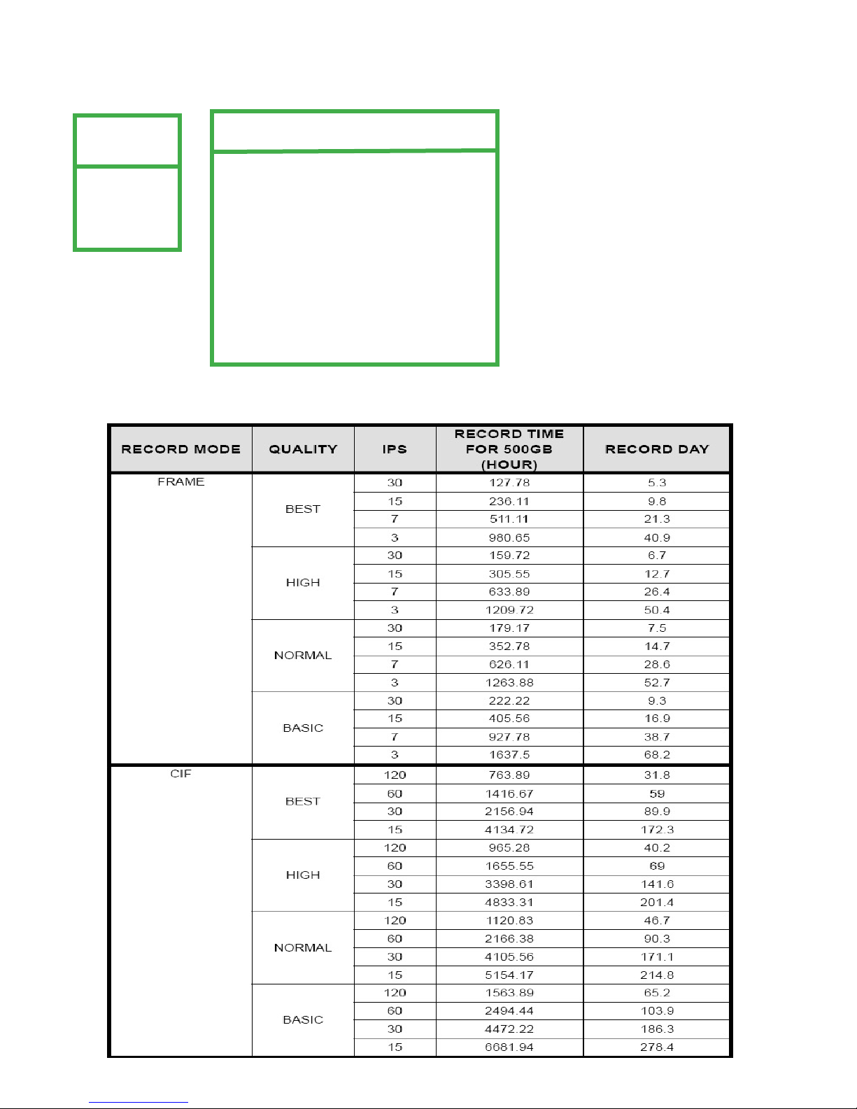
4.8 RECORD QUALITY AND IPS
Select RECORD from the main menu and press the ENTER key. Set EVENT RECORD ENABLE to YES.
MENU
RECORD
TIMER
DATE
ADVANCE
Use Table 1 to set your RECORD QUALITY and IPS.
RECORD
MANUAL RECORD ENABLE NO
EVENT RECORD ENABLE YES
TIMER RECORD ENABLE NO
OVERWRITE YES
RECORD IMG SIZE FRAME
RECORD QUALITY BASIC
MANUAL RECORD IPS 030
EVENT RECORD IPS 030
TIMER RECORD IPS 030
TOTAL IPS SHARE FIX
TABLE 1
20
 Loading...