

Super Circuits DMR40DVD, DMR41DVD, DMR42DVD User Manual

H.264 Network DVR
User Manual
Product: DMR40DVD, DMR41DVD, DMR42DVD
Please read this manual before using your recorder, and always follow the
instructions for safety and proper use. Save this manual for future reference.
DMR40-41-42DVD_RM
ii
www.supercircuits.com
WARNING
!
Do not expose this product to liquids. Objects lled with liquids, such as vases, should be
kept away.
CAUTION
This is a Safety Class 1 Product (provided with a protective earth ground incorporated
in the power cord). The mains plug must be inserted in a electrical outlet provided with
a protective earth contact. A break in the protective conductor inside or outside of the
product can be dangerous. Tampering with the protective earth ground circuit is prohibited.
This product complies with radio interference requirements.
LEGAL NOTICE
Supercircuits products are designed to meet safety and performance standards with the use of specic
Supercircuits authorized accessories. Supercircuits disclaims liability associated with the use of nonSupercircuits authorized accessories.
The recording, transmission, or broadcast of any person’s voice without their consent or a court order is
strictly prohibited by law.
Supercircuits makes no representations concerning the legality of certain product applications such as
the making, transmission, or recording of video and/or audio signals of others without their knowledge
and/or consent. We encourage you to check and comply with all applicable local, state, and federal laws
and regulations before engaging in any form of surveillance or any transmission of radio frequencies.
Other trademarks and trade names may be used in this document to refer to either the entities claiming
the marks and names or their products. Supercircuits, Inc. disclaims any proprietary interest in
trademarks and trade names other than its own.
No part of this document may be reproduced or distributed in any form or by any means without the
express written permission of Supercircuits, Inc.
© 2010 Supercircuits, Inc. All rights reserved.
11000 N. Mopac Expressway, Building 300, Austin, TX 78759
Sales/Support: 1.800.335.9777 | Fax: 1.866.267.9777

iiiH.264 Network DVR User Manual
Table of Contents
SECTION 1 Product Description . . . . . . . . . . . . . . . . . . . . . . . . . . . . . . . . . . . . . . . . . . . . . . 1
1.1 Features . . . . . . . . . . . . . . . . . . . . . . . . . . . . . . . . . . . . . . . . . . . . . . . . . . . 1
1.2 Package Contents . . . . . . . . . . . . . . . . . . . . . . . . . . . . . . . . . . . . . . . . . . . 2
SECTION 2 Front and Rear Panel Controls and Indicators . . . . . . . . . . . . . . . . . . . . . . . . . . 3
2.1 Front Panel . . . . . . . . . . . . . . . . . . . . . . . . . . . . . . . . . . . . . . . . . . . . . . . . . 3
2.1.1 LED Indicators: . . . . . . . . . . . . . . . . . . . . . . . . . . . . . . . . . . . . . . . . . . 3
2.1.2 Buttons . . . . . . . . . . . . . . . . . . . . . . . . . . . . . . . . . . . . . . . . . . . . . . . . 3
2.2 Rear Panel . . . . . . . . . . . . . . . . . . . . . . . . . . . . . . . . . . . . . . . . . . . . . . . . . 5
SECTION 3 Connections and Setup . . . . . . . . . . . . . . . . . . . . . . . . . . . . . . . . . . . . . . . . . . . 7
3.1 HDD installation . . . . . . . . . . . . . . . . . . . . . . . . . . . . . . . . . . . . . . . . . . . . . 7
3.1.1 HDD installation for DMR42DVD and DMR41DVD . . . . . . . . . . . . . . . 7
3.1.2 HDD installation for DMR40DVD . . . . . . . . . . . . . . . . . . . . . . . . . . . . 9
3.2 Camera connection . . . . . . . . . . . . . . . . . . . . . . . . . . . . . . . . . . . . . . . . . 11
3.2.1 Regular Camera Connection . . . . . . . . . . . . . . . . . . . . . . . . . . . . . . . 11
3.2.2 Speed Dome camera RS485 cabling. . . . . . . . . . . . . . . . . . . . . . . . . 11
SECTION 4 DVR Software Usage . . . . . . . . . . . . . . . . . . . . . . . . . . . . . . . . . . . . . . . . . . . . 14
4.1 Power on the DVR . . . . . . . . . . . . . . . . . . . . . . . . . . . . . . . . . . . . . . . . . . 14
4.2 Menu tree* . . . . . . . . . . . . . . . . . . . . . . . . . . . . . . . . . . . . . . . . . . . . . . . . 14
4.3 Menu operations keys . . . . . . . . . . . . . . . . . . . . . . . . . . . . . . . . . . . . . . . 15
4.4 QUICK START menu . . . . . . . . . . . . . . . . . . . . . . . . . . . . . . . . . . . . . . . . . 16
4.4.1 STATUS. . . . . . . . . . . . . . . . . . . . . . . . . . . . . . . . . . . . . . . . . . . . . . . 16
4.4.2 RECORD . . . . . . . . . . . . . . . . . . . . . . . . . . . . . . . . . . . . . . . . . . . . . . 16
4.4.3 TIMER. . . . . . . . . . . . . . . . . . . . . . . . . . . . . . . . . . . . . . . . . . . . . . . . 17
4.4.4 DATE . . . . . . . . . . . . . . . . . . . . . . . . . . . . . . . . . . . . . . . . . . . . . . . . . 19
4.4.5 Setting the date and time . . . . . . . . . . . . . . . . . . . . . . . . . . . . . . . . . 21
4.5 ADVANCE CONFIG . . . . . . . . . . . . . . . . . . . . . . . . . . . . . . . . . . . . . . . . . . 22
4.5.1 CAMERA menu . . . . . . . . . . . . . . . . . . . . . . . . . . . . . . . . . . . . . . . . 22
4.5.2 DETECTION. . . . . . . . . . . . . . . . . . . . . . . . . . . . . . . . . . . . . . . . . . . . 23
4.5.3 Alert . . . . . . . . . . . . . . . . . . . . . . . . . . . . . . . . . . . . . . . . . . . . . . . . . 25
4.5.4 Network . . . . . . . . . . . . . . . . . . . . . . . . . . . . . . . . . . . . . . . . . . . . . . 26
4.5.5 SNTP . . . . . . . . . . . . . . . . . . . . . . . . . . . . . . . . . . . . . . . . . . . . . . . . 29
4.5.6 DISPLAY . . . . . . . . . . . . . . . . . . . . . . . . . . . . . . . . . . . . . . . . . . . . . . 29
4.5.7 RECORD . . . . . . . . . . . . . . . . . . . . . . . . . . . . . . . . . . . . . . . . . . . . . . 30
4.5.8 REMOTE . . . . . . . . . . . . . . . . . . . . . . . . . . . . . . . . . . . . . . . . . . . . . . 31
4.5.9 PTZ camera setup . . . . . . . . . . . . . . . . . . . . . . . . . . . . . . . . . . . . . . . 32
4.6 SYSTEM INFO . . . . . . . . . . . . . . . . . . . . . . . . . . . . . . . . . . . . . . . . . . . . . 33

iv
www.supercircuits.com
TABLES OF CONTENTS
4.6.1 Setting the password . . . . . . . . . . . . . . . . . . . . . . . . . . . . . . . . . . . . 34
4.7 EVENT INFO . . . . . . . . . . . . . . . . . . . . . . . . . . . . . . . . . . . . . . . . . . . . . . . 34
4.7.1 Quick Search . . . . . . . . . . . . . . . . . . . . . . . . . . . . . . . . . . . . . . . . . . 35
4.7.2 Event Search . . . . . . . . . . . . . . . . . . . . . . . . . . . . . . . . . . . . . . . . . . . 35
4.7.3 HDD INFO . . . . . . . . . . . . . . . . . . . . . . . . . . . . . . . . . . . . . . . . . . . . . 36
4.7.4 EVENT LOG . . . . . . . . . . . . . . . . . . . . . . . . . . . . . . . . . . . . . . . . . . . . 36
4.8 BACKUP . . . . . . . . . . . . . . . . . . . . . . . . . . . . . . . . . . . . . . . . . . . . . . . . . . 37
4.8.1 USB BACKUP . . . . . . . . . . . . . . . . . . . . . . . . . . . . . . . . . . . . . . . . . . 38
4.8.2 DISK BACKUP (selected models) . . . . . . . . . . . . . . . . . . . . . . . . . . . 39
SECTION 5 Basic Operation . . . . . . . . . . . . . . . . . . . . . . . . . . . . . . . . . . . . . . . . . . . . . . . . 41
5.1 Live page . . . . . . . . . . . . . . . . . . . . . . . . . . . . . . . . . . . . . . . . . . . . . . . . . 41
5.1.1 Recording icons . . . . . . . . . . . . . . . . . . . . . . . . . . . . . . . . . . . . . . . . 42
5.2 Playback . . . . . . . . . . . . . . . . . . . . . . . . . . . . . . . . . . . . . . . . . . . . . . . . . . 42
5.3 Key lock and unlock . . . . . . . . . . . . . . . . . . . . . . . . . . . . . . . . . . . . . . . . . 43
5.4 Firmware upgrade . . . . . . . . . . . . . . . . . . . . . . . . . . . . . . . . . . . . . . . . . . 43
5.5 Search . . . . . . . . . . . . . . . . . . . . . . . . . . . . . . . . . . . . . . . . . . . . . . . . . . . 44
SECTION 6 Local and Remote Operation . . . . . . . . . . . . . . . . . . . . . . . . . . . . . . . . . . . . . . 45
6.1 Networking your DVR . . . . . . . . . . . . . . . . . . . . . . . . . . . . . . . . . . . . . . . 45
6.2 Video Viewer software . . . . . . . . . . . . . . . . . . . . . . . . . . . . . . . . . . . . . . . 45
6.2.1 Install Video Viewer software . . . . . . . . . . . . . . . . . . . . . . . . . . . . . . 46
6.2.2 Network connection via LAN/WAN . . . . . . . . . . . . . . . . . . . . . . . . . . 46
6.2.3 Video Viewer displays . . . . . . . . . . . . . . . . . . . . . . . . . . . . . . . . . . . 47
6.2.4 Operations . . . . . . . . . . . . . . . . . . . . . . . . . . . . . . . . . . . . . . . . . . . . 49
6.2.5 E-Map features . . . . . . . . . . . . . . . . . . . . . . . . . . . . . . . . . . . . . . . . . 52
6.3 Web browser . . . . . . . . . . . . . . . . . . . . . . . . . . . . . . . . . . . . . . . . . . . . . . 58
6.4 Apple QuickTime player . . . . . . . . . . . . . . . . . . . . . . . . . . . . . . . . . . . . . . 60
6.5 SC Mobile App for iPhone . . . . . . . . . . . . . . . . . . . . . . . . . . . . . . . . . . . . 62
6.5.1 Installation . . . . . . . . . . . . . . . . . . . . . . . . . . . . . . . . . . . . . . . . . . . . 62
6.5.2 Setup . . . . . . . . . . . . . . . . . . . . . . . . . . . . . . . . . . . . . . . . . . . . . . . . 64
6.5.3 Using the SC Mobile app . . . . . . . . . . . . . . . . . . . . . . . . . . . . . . . . . 66
6.5.4 Login to your DVR . . . . . . . . . . . . . . . . . . . . . . . . . . . . . . . . . . . . . . 67
6.5.5 Using the display features . . . . . . . . . . . . . . . . . . . . . . . . . . . . . . . . 67
6.5.6 PTZ camera control . . . . . . . . . . . . . . . . . . . . . . . . . . . . . . . . . . . . . 69
6.5.7 Swipe left, right, up, or down . . . . . . . . . . . . . . . . . . . . . . . . . . . . . . 71
6.5.8 Logout . . . . . . . . . . . . . . . . . . . . . . . . . . . . . . . . . . . . . . . . . . . . . . . 72

vH.264 Network DVR User Manual
TABLES OF CONTENTS
SECTION 7 Specifications . . . . . . . . . . . . . . . . . . . . . . . . . . . . . . . . . . . . . . . . . . . . . . . . . . 73
APPENDIX A D-sub Connector Pin Configuration . . . . . . . . . . . . . . . . . . . . . . . . . . . . . . . . . 75
A.1 DMR42DVD 25-pin D-sub connector configuration . . . . . . . . . . . . . . . . . 75
A.2 DMR41DVD 25-pin D-sub connector configuration . . . . . . . . . . . . . . . . . 76
A.3 DMR40DVD 15-pin D-sub connector configuration . . . . . . . . . . . . . . . . . 77
APPENDIX B Compatible USB Flash Drives . . . . . . . . . . . . . . . . . . . . . . . . . . . . . . . . . . . . . . 78
APPENDIX C Compatible HDD Models . . . . . . . . . . . . . . . . . . . . . . . . . . . . . . . . . . . . . . . . . 79
APPENDIX D Troubleshooting FAQ . . . . . . . . . . . . . . . . . . . . . . . . . . . . . . . . . . . . . . . . . . . . 80
APPENDIX E RS232 Protocol . . . . . . . . . . . . . . . . . . . . . . . . . . . . . . . . . . . . . . . . . . . . . . . . 82
APPENDIX F DVR Battery Replacement . . . . . . . . . . . . . . . . . . . . . . . . . . . . . . . . . . . . . . . . 84
APPENDIX G Recording Time Table . . . . . . . . . . . . . . . . . . . . . . . . . . . . . . . . . . . . . . . . . . . 85
Tables
TABLE 1. Menu operations keys . . . . . . . . . . . . . . . . . . . . . . . . . . . . . . . . . . . . . . . . . . . 15
TABLE 2. Detection area setup . . . . . . . . . . . . . . . . . . . . . . . . . . . . . . . . . . . . . . . . . . . . 24
TABLE 3. Live page icon definitions . . . . . . . . . . . . . . . . . . . . . . . . . . . . . . . . . . . . . . . . 41
TABLE 4. Video Viewer button functions . . . . . . . . . . . . . . . . . . . . . . . . . . . . . . . . . . . . . 48
TABLE 5. Video Viewer backup window parameters . . . . . . . . . . . . . . . . . . . . . . . . . . . . 52
TABLE 6. E-Map device tree icons . . . . . . . . . . . . . . . . . . . . . . . . . . . . . . . . . . . . . . . . . . 55
TABLE 7. Web browser button function. . . . . . . . . . . . . . . . . . . . . . . . . . . . . . . . . . . . . . 59
TABLE 8. PTZ Camera control buttons . . . . . . . . . . . . . . . . . . . . . . . . . . . . . . . . . . . . . . 70
TABLE 9. Specifications . . . . . . . . . . . . . . . . . . . . . . . . . . . . . . . . . . . . . . . . . . . . . . . . . . 73
TABLE 10. 25-pin D-sub configuration for DMR42DVD . . . . . . . . . . . . . . . . . . . . . . . . . . 75
TABLE 11. 25-pin D-sub configuration for DMR41DVD . . . . . . . . . . . . . . . . . . . . . . . . . . 76
TABLE 12. 25-pin D-sub configuration for DMR40DVD . . . . . . . . . . . . . . . . . . . . . . . . . . 77
TABLE 13. USB flash drive compatibility . . . . . . . . . . . . . . . . . . . . . . . . . . . . . . . . . . . . . . 78
TABLE 14. HDD compatibility . . . . . . . . . . . . . . . . . . . . . . . . . . . . . . . . . . . . . . . . . . . . . . 79
TABLE 15. FAQ (Frequently Asked Questions) . . . . . . . . . . . . . . . . . . . . . . . . . . . . . . . . . . 80
TABLE 16. RS232 protocol functions and codes . . . . . . . . . . . . . . . . . . . . . . . . . . . . . . . . 82
TABLE 17. HDD usage for 16 channel recording . . . . . . . . . . . . . . . . . . . . . . . . . . . . . . . . 85
TABLE 18. HDD usage for 8 channel recording . . . . . . . . . . . . . . . . . . . . . . . . . . . . . . . . . 85
TABLE 19. HDD usage for 4 channel recording . . . . . . . . . . . . . . . . . . . . . . . . . . . . . . . . . 86

vi
www.supercircuits.com

1H.264 Network DVR User Manual
SECTION 1: PRODUCT DESCRIPTION
SECTION 1
Product Description
The DMR40DVD, DMR41DVD, and DMR42DVD network DVRs includes H.264 technology for improved
video quality, higher storage density, and faster le acquisition across the network. Recording backups
can be performed through a USB port and/or an optional DVD writer. Depending on the model, they also
support up to two internal SATA HDDs. All models come with an IR remote control.
1.1 Features
Your DVR includes the following special features:
• H.264 t4echnology for improved video quality, higher compression, and faster le transfer
• VGA support
• Graphical and multi-language OSD
• Remote independent operation – Allows single-channel viewing of remote cameras without
changing display settings on the monitor connected to the DVR.
• Pentaplex operation: simultaneous live display, record, playback, backup, and network operations
• Excellent image quality and performance. Frame image quality is clear and detailed video
• Intelligent motion trigger recording
— Selectable motion detection areas in each channel, scheduled motion detection recording,
and quick search
— Supports pre-alarm recording (up to 30 seconds)
— Activates event recording on alarm. Sends an email with the event snapshot to designated
e-mails/FTP addresses
• Backup devices – Supports USB 2.0 ash drive, DVD writer, and network
• Remote surveillance – Supports remote surveillance by up to 10 users simultaneously with Video
Viewer software, Microsoft
®
Internet Explorer®/Mozilla® Firefox®/Apple® Safari® web browser, and
QuickTime
®
player. Can be accessed with SC Mobile Apple® iPhone® app (view only).
• Covert recording mode: blank screen replaces live displays during covert recording
• Audio support
• General
— Supports internal SATA HDD
— Supports IR remote control
— System auto recovery after power failure
— Supports PTZ camera operations through RS485
— Supports daylight saving time
— Supports manual/timer/motion/network recording
— Supports TCP/IP, PPPoE, and DHCP network connection.
— Supports DDNS updating

2
www.supercircuits.com
SECTION 1: PRODUCT DESCRIPTION
1.2 Package Contents
Your DVR product includes the following:
• Digital video recorder (DVR)
• HDD bracket and screws
• Power adapter and power cord
• D-sub connector
• IR remote control
• IR receiver (optional)
• AAA size battery (2)
• CD-ROM (with this manual and Video Viewer software)
• Quick Start Guide and IR remote control manual
3H.264 Network DVR User Manual
SECTION 2: FRONT AND REAR PANEL CONTROLS
SECTION 2
Front and Rear Panel Controls and Indicators
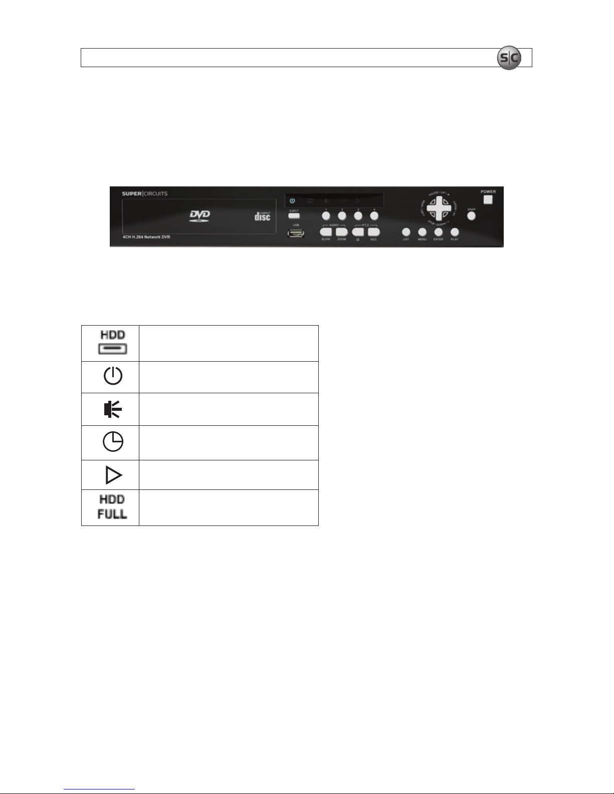
2.1 Front Panel
DMR40DVD front panel
2.1.1 LED Indicators:
HDD is reading or recording
DVR is powered on
An alarm is triggered
Timer recording is on
Playback status (DMR40DVD only)
HDD is full (DMR42DVD and DMR41DVD only)
2.1.2 Buttons
MENU – Press MENU to open the main menu.
ENTER – Press ENTER to apply and conrm the setting.
SLOW – In playback mode, press SLOW to slow playback.
ZOOM – In FRAME or FIELD recording mode, press to enlarge the view of the selected channel.

4
www.supercircuits.com
SECTION 2: FRONT AND REAR PANEL CONTROLS
– Press for 4 channel display mode.
SEQ – Press to activate the call monitor function. Press again to exit Monitor mode.
POWER – Press and hold for 5 seconds to turn the DVR on/off. When the DVR is recording mode, stop
recording before turning off the DVR.
CH1 ~ 16 / CH1 ~ 8 / CH1 ~ 4 – Press the channel number buttons to select the channel to display.
PLAY – Press to playback recorded data.
p / q / t / u – Directional keys.
• In MENU mode to move the cursor up/down/left/right
• In PTZ mode to move the camera direction up/down/left/right
• Use to control recorded video playback:
— p – pause play
— q – to stop play
— u – fast forward
— t – rewind
AUDIO (SLOW + ZOOM) – Press to select live or playback sounds from the audio channels.
Live audio of the 1st audio channel
Playback audio of the 1st audio channel
Live audio of the 2nd audio channel
Playback audio of the 2nd audio channel
Live audio of the 3rd audio channel
Playback audio of the 3rd audio channel
Live audio of the 4th audio channel
Playback audio of the 4th audio channel
The audio channel is not selected.
PTZ – Select the PTZ camera channel and open a full-screen display, then press + SEQ at the same
time to enter/exit the PTZ control mode.

5H.264 Network DVR User Manual
SECTION 2: FRONT AND REAR PANEL CONTROLS
In the PTZ control mode:
– Zoom in – Press SEQ
– Zoom out – Press
– Adjust pan and tilt angle – Press p / q / t / u
LIST (Event List Search) – To quickly search recorded les by event, click to list les in the event lists.
SNAP – Press to take a snapshot.
NOTE
Before making a snapshot, insert a compatible USB ash drive into the USB port. Refer to
Appendix B.
REC (DMR42DVD and DMR41DVD only) – Press to start manual recording function when this function is
disabled.
EJECT – Press to open or close the DVD tray.
USB – Supports rmware upgrade and le backup.
2.2 Rear Panel
DMR40DVD back panel
75Ω/HI-IMPEDANCE switch – Set this switch to HI-IMPEDANCE when using the LOOP connector to
extend the INPUT signal to another device or INPUT channel. Otherwise, set to 75Ω.
INPUT (1 ~ 16/1 ~ 8/1 ~ 4) – Connect to video sources (cameras).
LOOP (1 ~ 16/1 ~ 8/1 ~ 4) – Video output connector (with selected models only).
NOTE
The DVR automatically detects the video signal of a camera when the camera is connected to the
DVR and powered on before the DVR is powered on.
MONITOR – video output to monitor.

6
www.supercircuits.com
SECTION 2: FRONT AND REAR PANEL CONTROLS
CALL – Connect to a sequencing call monitor.
AUDIO channels 1, 2, 3, 4 – Connect to camera audio or other audio sources. The audio input is
recorded when the associated video input channel is recorded.
NOTE
To make a video backup with audio, camera which supports the audio function must be
connected to a video channel (INPUT) which supports audio recording. Up to four channels for
audio recording are supported:
AUDIO 1 audio data is recorded with (video) INPUT channel 1.
AUDIO 2 audio data is recorded with INPUT channel 2.
AUDIO 3 audio data is recorded with INPUT channel 3.
AUDIO 4 audio data is recorded with INPUT channel 4.
Audio OUT – Connect to a monitor audio input or powered speaker with a mono audio input.
VGA – Connect directly to a monitor VGA (PC) input.
IR – Connect the IR receiver extension line (optional) for remote control.
RS485 – Connect to devices with an RS485-A and RS485-B interface (such as speed dome cameras).
(DMR42DVD and DMR41DVD only.)
EXTERNAL I/O – Attach the supplied 15- or 25-pin D-sub connector to this port for connecting external
devices (external alarm, etc). Refer to Appendix A. (Selected models only.)
LAN – Connect to a Ethernet network.
LINK / ACT LED – When the network is activated the LED light will be on.
DC 19V – Connect the DVR power adapter to this jack.

7H.264 Network DVR User Manual
SECTION 3: CONNECTIONS AND SETUP
SECTION 3
Connections and Setup
The hard disk drive (HDD) included in your system is a security grade device, factory tested and certied
to be functional with all operations of the DVR.
NOTE
Opening the DVR enclosure will void the warranty.
If you need to change the HDD installed in your DVR, return the device to Supercircuits for a
factory installation (preserves the warranty), or refer to the HDD compatibility list in Appendix C for
recommended HDD models. If installing an HDD, use the following instructions.
3.1 HDD installation
> > > OPENING THE DVR ENCLOSURE WILL VOID THE WARRANTY < < <
The HDD you install must be compatible with the DVR hardware. The DVR accommodates only SATA
HDDs. Refer to the HDD compatibility list in Appendix C.
CAUTION
The DVR must be powered off when installing an HDD.
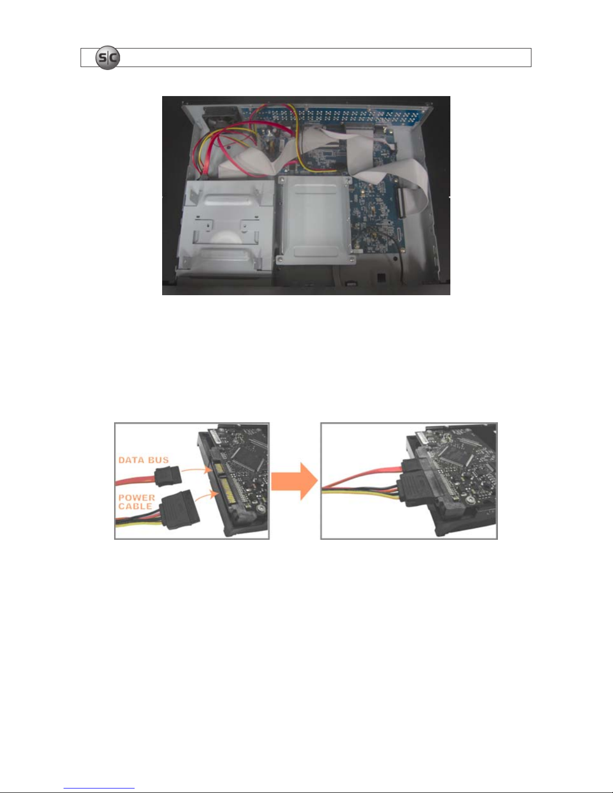
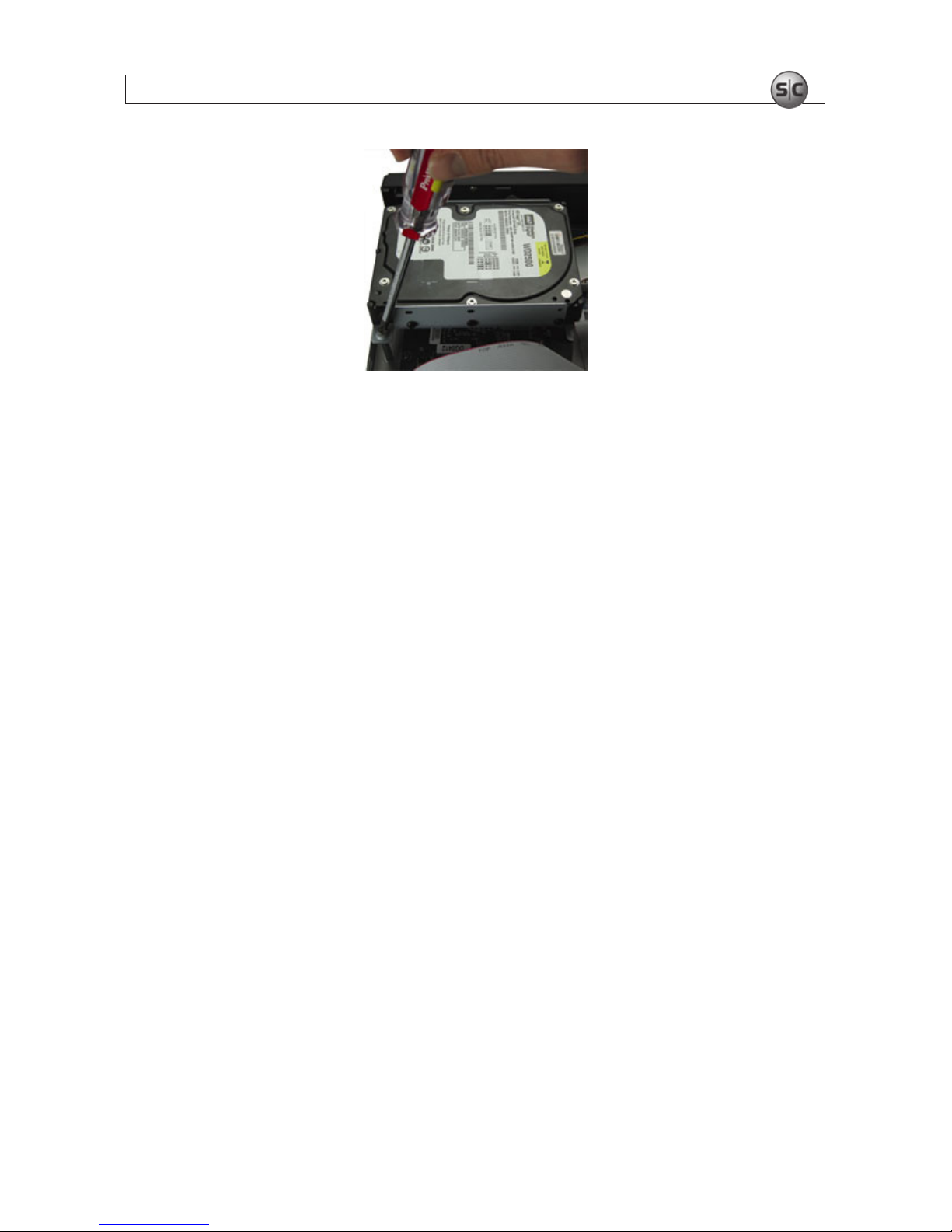
3.1.1 HDD installation for DMR42DVD and DMR41DVD
To install the HDD, do the following:
1. Power off the DVR and disconnect the power adapter.
2. Remove the DVR top cover.
3. With the front panel facing you, nd the two HDD brackets. One is on the left and one in the middle.
8
www.supercircuits.com
SECTION 3: CONNECTIONS AND SETUP
4. The HDD may be installed in the left or right bracket:
To install the HDD in the left bracket:
i. Orient the HDD so that the circuit board side is facing up. Connect the power and data
bus cables to the HDD.
ii. Position the HDD in the left bracket with the circuit board toward the bracket (down).
iii. Secure the HDD to the bracket with four screws, two on each side.
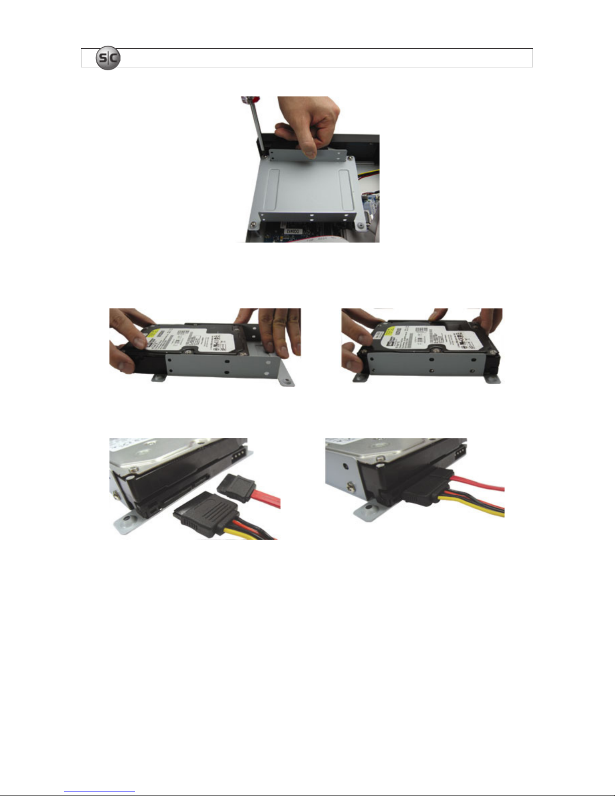
To install the HDD in the middle bracket:
i. Remove the middle bracket from the DVR chassis.
ii. Orient the HDD so that the circuit board side is facing up, then slide the HDD into the
bracket.
> > > OPENING THE DVR ENCLOSURE WILL VOID THE WARRANTY < < <

9H.264 Network DVR User Manual
SECTION 3: CONNECTIONS AND SETUP
iii. Secure the HDD to the bracket with four screws, two on each side.
iv. Connect the power and data bus cables to the HDD (see photos above).
v. Place the bracket (with the HDD) back into the DVR and secure it to the chassis.
5. Reinstall the DVR top cover.
6. Reconnect the power adapter.
3.1.2 HDD installation for DMR40DVD
For DVRs with a DVD drive, the HDD is installed in the right side bracket. For DVRs without a DVD drive,
the HDD is installed in the bracket on the left.
NOTE
The following describes an HDD installation into a 4-channel DVR WITHOUT a DVD drive. If your
DVR has a DVD drive, ignore steps 3.a and 3.d.
1. Power off the DVR and disconnect the power adapter.
2. Remove the DVR top cover.
3. Position the DVR so that you are facing the rear panel.
a. Remove the left HDD bracket from the chassis. If your DVR includes a DVD drive, skip this
step and continue with step 3b.
> > > OPENING THE DVR ENCLOSURE WILL VOID THE WARRANTY < < <
10
www.supercircuits.com
SECTION 3: CONNECTIONS AND SETUP
b. Position the HDD in the bracket with the circuit board side toward the bracket. Secure the
HDD to the bracket with four screws, two on each side.
c. Connect the power and data bus cables to the HDD.
d. Reattach the bracket (with the HDD) to the DVR chassis. Skip this step if your DVR has a DVD
drive.
> > > OPENING THE DVR ENCLOSURE WILL VOID THE WARRANTY < < <
11H.264 Network DVR User Manual
SECTION 3: CONNECTIONS AND SETUP
4. Reinstall the DVR top cover.
5. Reconnect the power adapter.
3.2 Camera connection
Refer to the documentation supplied with your camera for installation and setup instructions. For most
cameras, the following must be completed before power is applied to the DVR.
3.2.1 Regular Camera Connection
Following is a typical method for connecting cameras to the DVR. Refer to the camera user
documentation for specic instructions.
1. Audio cable connection (optional) – Connect the camera audio output cable to an Audio IN
connector on the DVR.
2. Video cable connection – Connect the camera video output cable to the video input connector on
the DVR. If the camera provides audio, plug the video cable into the INPUT connector with the same
number as the connector where the audio (Audio In) is attached.
3. Power connection – Connect the power adapter to the camera.
3.2.2 Speed Dome camera RS485 cabling
Following is a typical method for connecting a speed dome camera to RS485 control signals from the
DVR. Refer to the camera user documentation for specic instructions.
1. Acquire an RJ11 cable of sufcient length and route it from the DVR to the speed dome camera.
> > > OPENING THE DVR ENCLOSURE WILL VOID THE WARRANTY < < <
12
www.supercircuits.com
SECTION 3: CONNECTIONS AND SETUP
12
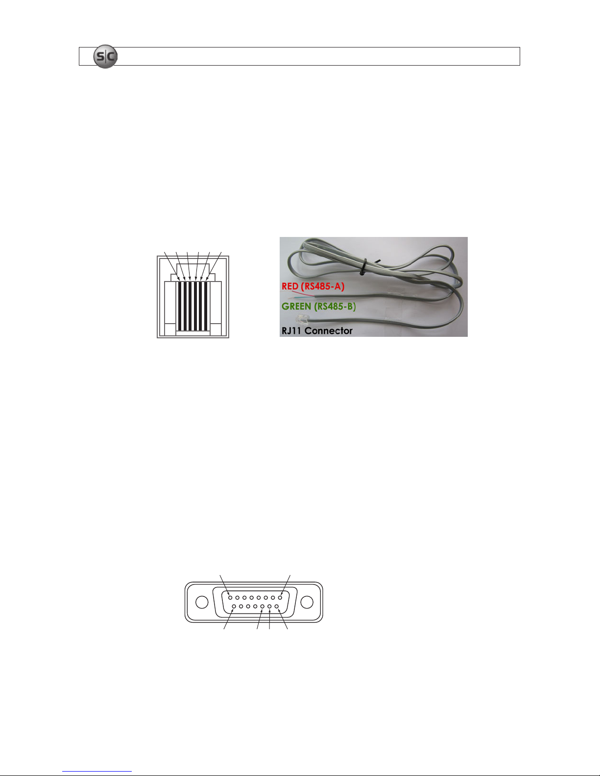
2. Connect the RJ11 cable to the DVR.
a. If an RS485 port is present on the DVR back panel (DMR41DVD, DMR42DVD only):
i. Examine the RJ11 connector. Record the colors of the center pair wires in the RJ11
connector that connect to pin 3 and pin 4 (center pair) of the RS485 port. These pins
provide the RS485-A and RS485-B signals to the camera. Usually these wire colors are
red and green respectively.
1 2 3 4 5 6
RS485 port
Pin 3: RS485-A
Pin 4: RS485-B
ii. Plug the RJ11 connector into the RS485 port.
b. If an EXTERNAL I/O port is present on the DVR back panel (DMR40DVD only):
i. At the DVR, remove the connector from the RJ11 cable and strip some insulation from
the red and green wires.
ii. Solder the RJ11 cable red wire to pin 11 on the 15-pin D-sub connector. See the
connector pin diagram below.
18
915 11 10
Pins
Pin 11: RS485-A
Pin 10: RS485-B
15-pin D-sub connector – solder side
iii. Solder the RJ11 cable green wire to pin 10 on the 15-pin D-sub connector.

13H.264 Network DVR User Manual
SECTION 3: CONNECTIONS AND SETUP
13
iv. Plug the 15-pin D-sub connector into the EXTERNAL I/O port.
3. At the camera, remove the RJ11 connector and insulation form the red and green wires in the
cable.
4. Connect the red wire (RS485-A signal) to the wire labeled RS485-A (or RS485+) at the speed
dome camera.
5. Connect the green wire (RS485-B signal) to the wire labeled RS485-B (or RS485–) at the speed
dome camera.
6. Seal the wire connections with insulating tape, shrink wrap, or equivalent to protect them from
moisture and from shorting to other conductors.
7. Check the camera conguration switches to determine the camera ID number, RS485 protocol and
baud rate. Save this information for use when conguring the DVR software for your system.
14
www.supercircuits.com
SECTION 4: DVR SOFTWARE USAGE
14
SECTION 4
DVR Software Usage
4.1 Power on the DVR
To power on the DVR:
1. Power on all cameras connected to the DVR and wait until they initialize.
2. Connect the DVR power cable to the power adapter and to the DVR, then plug the power adapter
into an electrical outlet.
3. Press the POWER button on the front of the DVR. The DVR power LED will be lit. When the DVR
initializes, it automatically senses the cameras connected to it.
4.2 Menu tree*
QUICK START
MENU
STATUS
CHANNEL TITLE
EVENT STATUS
DATE DISPLAY
RECORD
IMAGE SIZE
QUA LI TY
IMAGE PER SECOND
TIMER
RECORD TIMER
DETECTION TIMER
DATE
DATE
FORMAT
DAYLIGHT SAVING
ADVA NCED
MENU
ADVA NCE
CONFIG
CAMER A
DETECTION
ALERT
NETWORK
SNTP
DISPL AY
RECORD
REMOTE

15H.264 Network DVR User Manual
SECTION 4: DVR SOFTWARE USAGE
15
ADVA NCED
MENU
(cont.)
SYSTEM INFO
SERIA L TYPE
BAUD RATE
HOST ID
PASSWORD
RESET DEFAULT
CLE AR HDD
UPGRADE
R.E.T.R. (MIN) (selected models)
AUTO KE YLOCK (SEC)
LANGUAGE
VIDEO FORM AT
VERSION
EVENT INFO
QUICK SEARCH
EVENT SEARCH
HDD INFO
EVENT LOG
BACKUP
USB BACKUP
DISK BACKUP (selected models)
* Icons included in this menu tree differ between DVR models.
4.3 Menu operations keys
Refer to the following table to move through the menu system and make conguration settings.
Table 1. Menu operations keys
Item Function
QUICK START menu View and change the settings of the QUICK START menu items.
MENU Enter/exit the QUICK START menu
p q
Make the selection/Change the setting
t u
Go to the upper layer or sub-layer. Make a selection
ENTER Conrm entry
ADVANCED MENU:
In the QUICK START menu, move to
, then press q to open the advanced setting menu.
ENTER Go to the sub-layer of the advanced menu
MENU In a submenu, use this button to conrm the settings you selected and return to the higher level
menu.
16
www.supercircuits.com
16
Item Function
g NEXT
Move to this item then press ENTER to go the next page.
f BACK
Move to this item then press ENTER to go the previous page.
Other operations in the ADVANCED menu are the same as in the QUICK START menu.
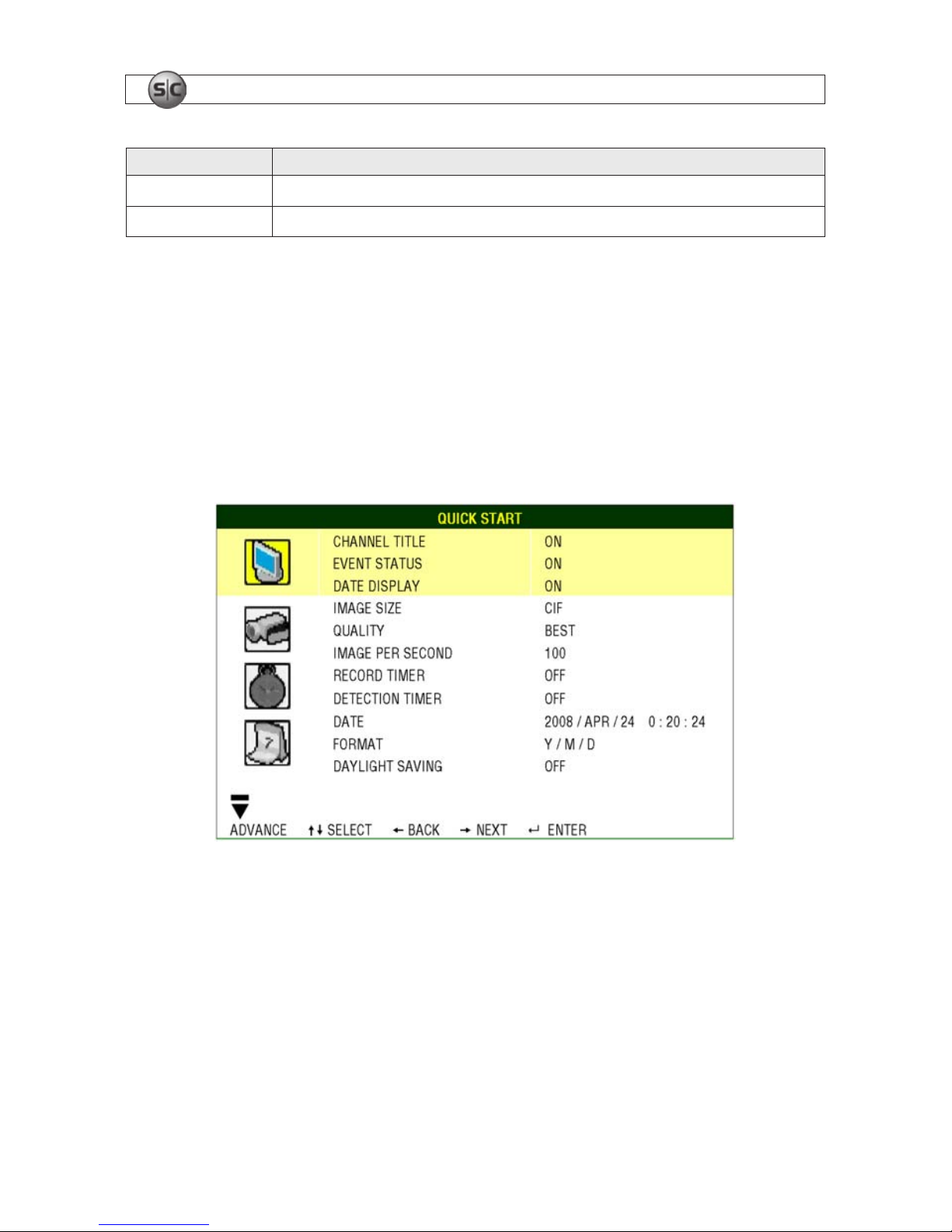
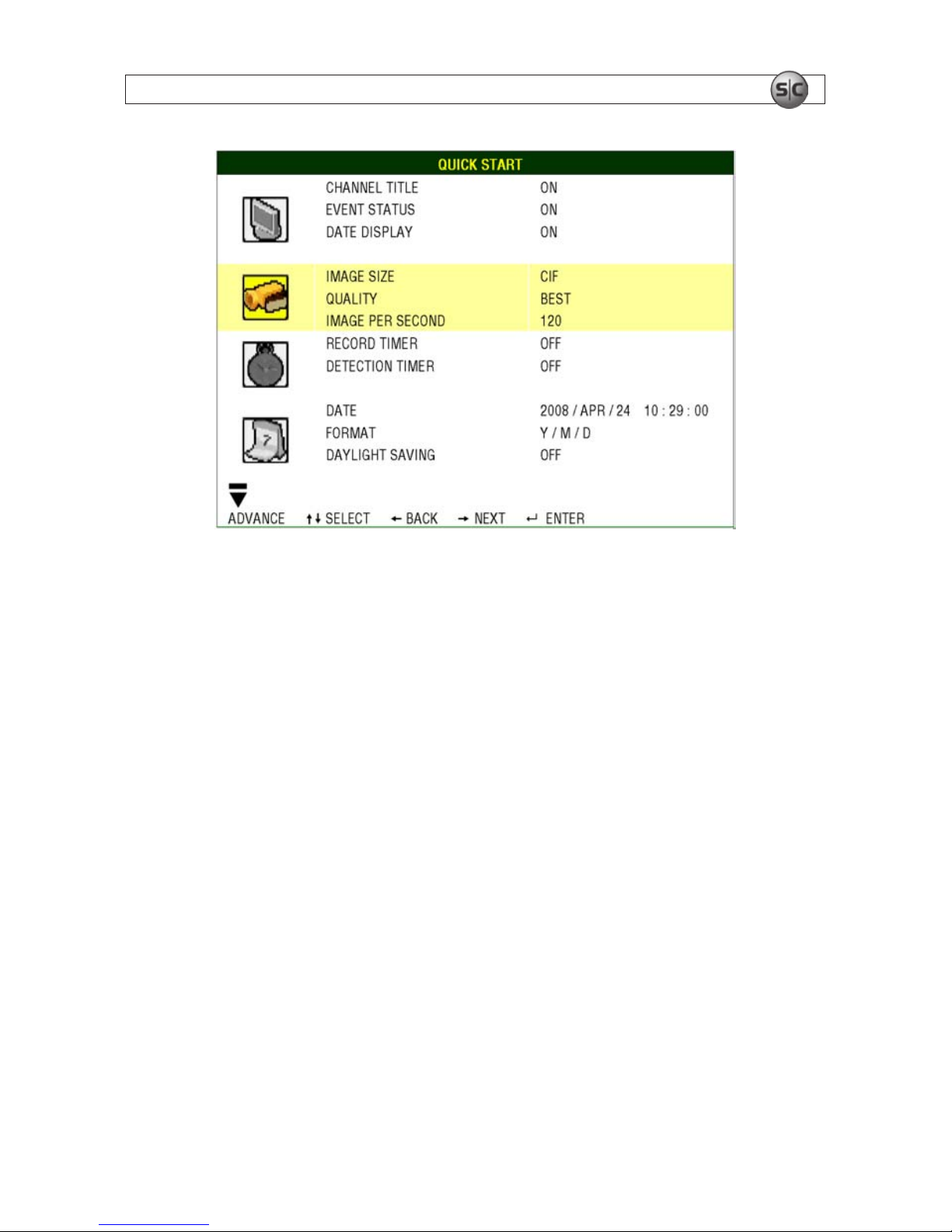
4.4 QUICK START menu
Press MENU and enter the password to open the QUICK START menu.
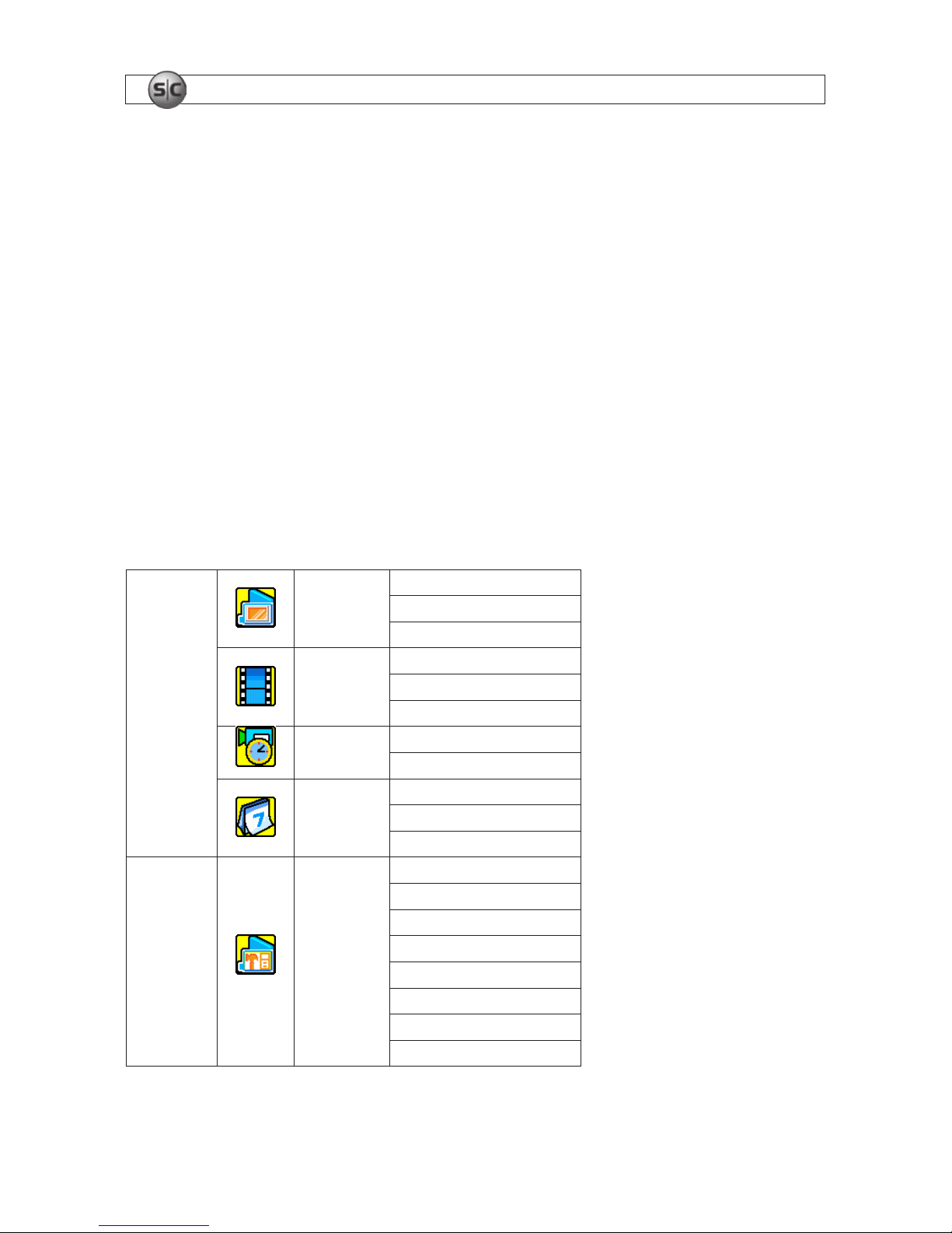
4.4.1 STATUS
In the QUICK START menu, go to the Status icon to view the following screen:
The QUICK START STATUS submenu includes:
• CHANNEL TITLE – Display channel title (ON/OFF).
• EVENT STATUS – Display symbols of the event (ON/OFF).
• DATE DISPLAY – Display the date, status icons and remaining HDD capacity (ON/OFF).
4.4.2 RECORD
In the QUICK START menu, go to the RECORD icon to view the following screen:
SECTION 4: DVR SOFTWARE USAGE
17H.264 Network DVR User Manual
SECTION 4: DVR SOFTWARE USAGE
17
The QUICK START record submenu includes the following parameters:
• IMAGE SIZE – Select either FRAME, FIELD or CIF.
• QUALITY – Select either SUPER BEST, BEST, HIGH or NORMAL.
• IMAGE PER SECOND – Select the images per second for MANUAL RECORD.
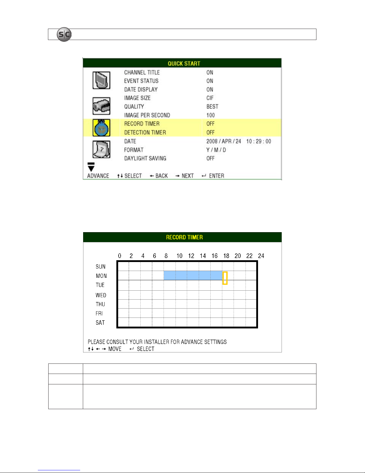
4.4.3 TIMER
In the QUICK START menu, go to the TIMER icon to view the following screen. In the timer section, you
can schedule time frames for the recording and detection functions.
18
www.supercircuits.com
SECTION 4: DVR SOFTWARE USAGE
18
The RECORD TIMER submenu is used to setup a recording schedule that repeats weekly.
• RECORD TIMER – Use the p and/or q buttons to change the setting (ON/OFF). When set to ON
press ENTER to open the submenu for setting the record time.
X axis 0 ~ 24 hours. Each time interval within a square is two hours divided into four 30-minute segments.
Y axis Sunday ~ Saturday
Operation
Move to the start time point then press ENTER to set the starting time (marked in red color). Use p, q, t, or
u to move forward in time to the ending time. Press ENTER again to mark the ending time (marked in yellow).
Press MENU to exit.
19H.264 Network DVR User Manual
SECTION 4: DVR SOFTWARE USAGE
19
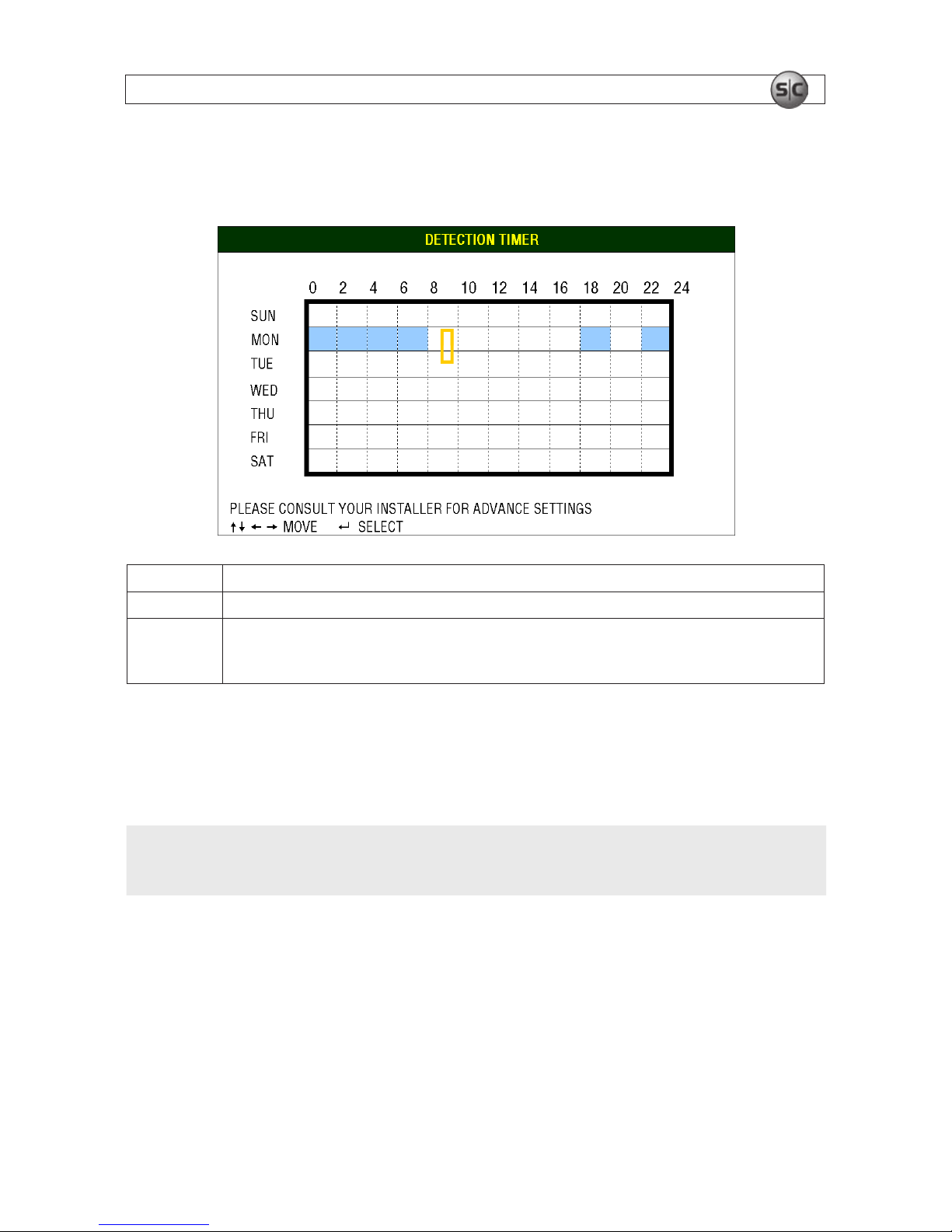
• DETECTION TIMER – Use the p and/or q buttons to change the setting (ON/OFF). When it is
ON, press ENTER to open the submenu for setting detection sensing time.
X axis 0 ~ 24 hours. Each time interval within a square is two hours divided into four 30-minute segments.
Y axis Sunday ~ Saturday
Operation
Move to the start time point then press ENTER to set the starting time (marked in red color). Use p, q, t, or
u to move forward in time to the ending time. Press ENTER again to set the ending time (marked in yellow).
Press MENU to exit.
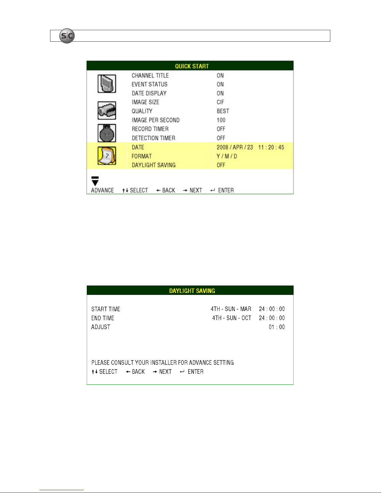
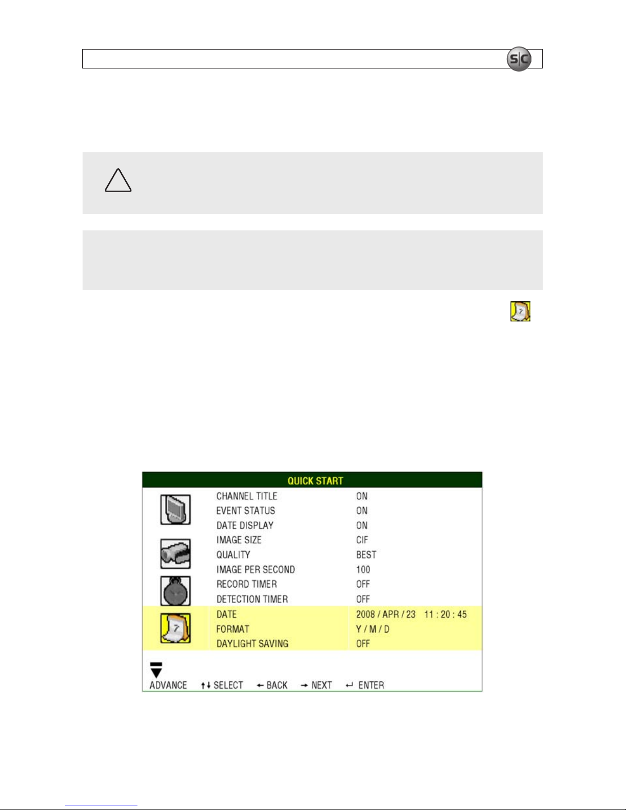
4.4.4 DATE
In the QUICK START menu, go to the DATE icon to set the system date and time. This setting should only
be made during initial setup of the DVR and after replacing the DVR battery.
NOTE
DO NOT change the date or time of your DVR after the recording function is activated. Since
recorded data is time stamped, old data may become unusable. If the date or time is changed
after recording is activated, clear all HDD data.
20
www.supercircuits.com
SECTION 4: DVR SOFTWARE USAGE
The DATE submenu items are described below:
• DATE – Set the current date and time. The default order is YEAR / MONTH / DAY HOUR : MIN :
SEC.
• FORMAT – Select one date format from the following 3 options: Y/M/D, M/D/Y, D/M/Y.
• DAYLIGHT SAVING – Use the p and/or q buttons to enable or disable automatic daylight saving
time correction (ON/OFF). When set to ON, press ENTER to open to a submenu to set the start and
end time.
The example above shows that daylight saving time is setup to begin on the 4th Sunday of March and
end on the 4th Sunday of October. During that period, system time will increase by one hour.
After setting the DAYLIGHT SAVINGS time parameters, press MENU to exit.
21H.264 Network DVR User Manual
SECTION 4: DVR SOFTWARE USAGE
4.4.5 Setting the date and time
Before using your DVR, set the current date and time. All recorded data is time stamped.
CAUTION
DO NOT change the date or time of your DVR after recording anything. Otherwise, the data
recorded will be disordered and it will be difcult to nd information you may be searching
for. If the date or time is changed, clear all HDD data before recording again.
NOTE
After setting the date and time for the rst time leave the DVR powered on for at least 48
hours. This helps prevent DVR time from resetting after disconnecting power from the unit.
If the DVR time resets after a power loss, the internal battery may be expended. See “DVR
Battery Replacement” in the appendix.
1. On the QUICK START menu, use the q directional button on the front panel to move to the
(Date) icon. Press u to select the DATE option.
2. Use the u, t, p and q directional buttons to set the date, time, and daylight saving time option
in this menu.
3. Press MENU to conrm your selection.
4. If an option to clear the HDD appears, choose YES then press ENTER.
22
www.supercircuits.com
SECTION 4: DVR SOFTWARE USAGE
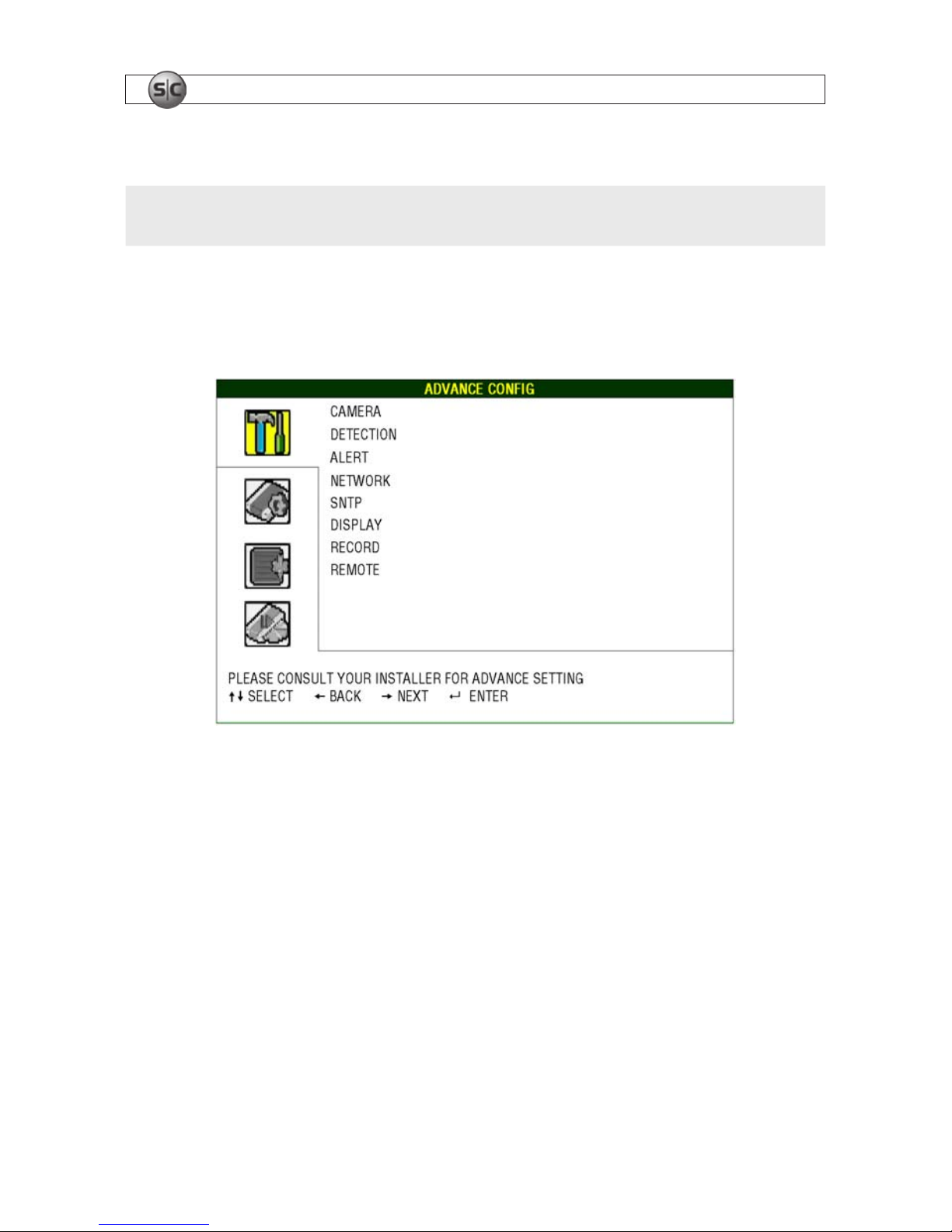
4.5 ADVANCE CONFIG
NOTE
The menu displays shown herein are for a 16-channel DVR. Displays for 8- and 4-channel units
differ slightly.
Press MENU and enter the password to open the QUICK START menu. Press the q button repeatedly
to open the ADVANCE CONFIG menu. In the ADVANCED CONFIG menu, you can setup the CAMERA/
DETECTION/ALERT/NETWORK/SNTP/DISPLAY/RECORD/REMOTE conguration.
4.5.1 CAMERA menu
In the CAMERA submenu, you can name the camera channel, adjust the video quality, and enable
recording of the channel.
 Loading...