

Super Circuits DMR27U User Manual

H.264 4-Channel DVR
User Manual
Product: DMR27U
Please read this manual before using your recorder, and always follow the instructions for
safety and proper use. Save this manual for future reference.
DMR27U_RM
ii
www.supercircuits.com
CAUTION
Operate this device only in environments where the temperature or humidity is within the recommended range.
Operation in extreme temperatures or humidity levels may cause electric shock and shorten the life of the
product.
CAUTION
Installation and servicing should be performed by qualied and experienced personnel only. DVR should always
remain OFF during any installation process.
CAUTION
Do not use the camera if fumes, smoke or a strange odor is emitted from the unit, or if it seems to function
incorrectly. Disconnect the power source immediately, and consult your dealer.
LEGAL NOTICE
Supercircuits products are designed to meet safety and performance standards with the use of specic
Supercircuits authorized accessories. Supercircuits disclaims liability associated with the use of non-Supercircuits
authorized accessories.
The recording, transmission, or broadcast of any person’s voice without their consent or a court order is strictly
prohibited by law.
Supercircuits makes no representations concerning the legality of certain product applications such as the
making, transmission, or recording of video and/or audio signals of others without their knowledge and/or
consent. We encourage you to check and comply with all applicable local, state, and federal laws and regulations
before engaging in any form of surveillance or any transmission of radio frequencies.
Other trademarks and trade names may be used in this document to refer to either the entities claiming the marks
and names or their products. Supercircuits, Inc. disclaims any proprietary interest in trademarks and trade names
other than its own.
No part of this document may be reproduced or distributed in any form or by any means without the express written
permission of Supercircuits, Inc.
© 2012 Supercircuits, Inc. All rights reserved.
11000 N. Mopac Expressway, Building 300, Austin, TX 78759
For Sales and Support, please contact your distributor.

iiiH.264 4-Channel DVR User Manual
Table of Contents
SECTION 1 Product Description . . . . . . . . . . . . . . . . . . . . . . . . . . . . . . . . . . . . . . . . . . . . . . . . . . . . . . . . . . . . . . . . . . . . . . . . . . . . . . 1
1.1 Features . . . . . . . . . . . . . . . . . . . . . . . . . . . . . . . . . . . . . . . . . . . . . . . . . . . . . . . . . . . . . . . . . . . . . . . . . . . . . . . . . . 1
1.2 Components . . . . . . . . . . . . . . . . . . . . . . . . . . . . . . . . . . . . . . . . . . . . . . . . . . . . . . . . . . . . . . . . . . . . . . . . . . . . . . 2
SECTION 2 Hardware Overview . . . . . . . . . . . . . . . . . . . . . . . . . . . . . . . . . . . . . . . . . . . . . . . . . . . . . . . . . . . . . . . . . . . . . . . . . . . . . . 3
2.1 Front panel . . . . . . . . . . . . . . . . . . . . . . . . . . . . . . . . . . . . . . . . . . . . . . . . . . . . . . . . . . . . . . . . . . . . . . . . . . . . . . . 3
2.2 Backpanel . . . . . . . . . . . . . . . . . . . . . . . . . . . . . . . . . . . . . . . . . . . . . . . . . . . . . . . . . . . . . . . . . . . . . . . . . . . . . . . . 4
2.3 DVR Hard disk drive . . . . . . . . . . . . . . . . . . . . . . . . . . . . . . . . . . . . . . . . . . . . . . . . . . . . . . . . . . . . . . . . . . . . . . . . 5
2.4 Remote control . . . . . . . . . . . . . . . . . . . . . . . . . . . . . . . . . . . . . . . . . . . . . . . . . . . . . . . . . . . . . . . . . . . . . . . . . . . . 5
SECTION 3 System Setup . . . . . . . . . . . . . . . . . . . . . . . . . . . . . . . . . . . . . . . . . . . . . . . . . . . . . . . . . . . . . . . . . . . . . . . . . . . . . . . . . . . 6
3.1 SETUP screen . . . . . . . . . . . . . . . . . . . . . . . . . . . . . . . . . . . . . . . . . . . . . . . . . . . . . . . . . . . . . . . . . . . . . . . . . . . . . 6
3.2 LIVE mode setup options . . . . . . . . . . . . . . . . . . . . . . . . . . . . . . . . . . . . . . . . . . . . . . . . . . . . . . . . . . . . . . . . . . . 7
3.3 RECORD setup options . . . . . . . . . . . . . . . . . . . . . . . . . . . . . . . . . . . . . . . . . . . . . . . . . . . . . . . . . . . . . . . . . . . . . . 8
3.4 SYSTEM SETUP mode . . . . . . . . . . . . . . . . . . . . . . . . . . . . . . . . . . . . . . . . . . . . . . . . . . . . . . . . . . . . . . . . . . . . . 11
3.5 NETWORK setup . . . . . . . . . . . . . . . . . . . . . . . . . . . . . . . . . . . . . . . . . . . . . . . . . . . . . . . . . . . . . . . . . . . . . . . . . . 13
3.6 STORAGE mode. . . . . . . . . . . . . . . . . . . . . . . . . . . . . . . . . . . . . . . . . . . . . . . . . . . . . . . . . . . . . . . . . . . . . . . . . . . 15
3.7 SAVE SETUP. . . . . . . . . . . . . . . . . . . . . . . . . . . . . . . . . . . . . . . . . . . . . . . . . . . . . . . . . . . . . . . . . . . . . . . . . . . . . . 16
SECTION 4 LIVE and SEARCH Modes . . . . . . . . . . . . . . . . . . . . . . . . . . . . . . . . . . . . . . . . . . . . . . . . . . . . . . . . . . . . . . . . . . . . . . . . . 17
4.1 LIVE window . . . . . . . . . . . . . . . . . . . . . . . . . . . . . . . . . . . . . . . . . . . . . . . . . . . . . . . . . . . . . . . . . . . . . . . . . . . . . 17
4.2 SEARCH window . . . . . . . . . . . . . . . . . . . . . . . . . . . . . . . . . . . . . . . . . . . . . . . . . . . . . . . . . . . . . . . . . . . . . . . . . 18
4.3 Play mode . . . . . . . . . . . . . . . . . . . . . . . . . . . . . . . . . . . . . . . . . . . . . . . . . . . . . . . . . . . . . . . . . . . . . . . . . . . . . . . 22
SECTION 5 Archiving and Backup . . . . . . . . . . . . . . . . . . . . . . . . . . . . . . . . . . . . . . . . . . . . . . . . . . . . . . . . . . . . . . . . . . . . . . . . . . . 24
5.1 Archiving still images . . . . . . . . . . . . . . . . . . . . . . . . . . . . . . . . . . . . . . . . . . . . . . . . . . . . . . . . . . . . . . . . . . . . . 24
5.2 BACKUP still images or video clip to a USB memory stick . . . . . . . . . . . . . . . . . . . . . . . . . . . . . . . . . . . . . . . . 26
5.3 Playing Backup video . . . . . . . . . . . . . . . . . . . . . . . . . . . . . . . . . . . . . . . . . . . . . . . . . . . . . . . . . . . . . . . . . . . . . 27
SECTION 6 Software Maintenance . . . . . . . . . . . . . . . . . . . . . . . . . . . . . . . . . . . . . . . . . . . . . . . . . . . . . . . . . . . . . . . . . . . . . . . . . . . 30
6.1 Firmware upgrade . . . . . . . . . . . . . . . . . . . . . . . . . . . . . . . . . . . . . . . . . . . . . . . . . . . . . . . . . . . . . . . . . . . . . . . . 30
6.2 Backup the setup conguration . . . . . . . . . . . . . . . . . . . . . . . . . . . . . . . . . . . . . . . . . . . . . . . . . . . . . . . . . . . . . 31
6.3 Load setup conguration. . . . . . . . . . . . . . . . . . . . . . . . . . . . . . . . . . . . . . . . . . . . . . . . . . . . . . . . . . . . . . . . . . . 32
SECTION 7 MClient – Network Client Viewer . . . . . . . . . . . . . . . . . . . . . . . . . . . . . . . . . . . . . . . . . . . . . . . . . . . . . . . . . . . . . . . . . 33
7.1 Overview . . . . . . . . . . . . . . . . . . . . . . . . . . . . . . . . . . . . . . . . . . . . . . . . . . . . . . . . . . . . . . . . . . . . . . . . . . . . . . . . 33
7.2 MClient Installation . . . . . . . . . . . . . . . . . . . . . . . . . . . . . . . . . . . . . . . . . . . . . . . . . . . . . . . . . . . . . . . . . . . . . . . 34
7.3 PC MClient setup conguration options . . . . . . . . . . . . . . . . . . . . . . . . . . . . . . . . . . . . . . . . . . . . . . . . . . . . . . 36
7.4 MClient – Live view . . . . . . . . . . . . . . . . . . . . . . . . . . . . . . . . . . . . . . . . . . . . . . . . . . . . . . . . . . . . . . . . . . . . . . . 40

iv
www.supercircuits.com
7.5 MClient – search and playback view . . . . . . . . . . . . . . . . . . . . . . . . . . . . . . . . . . . . . . . . . . . . . . . . . . . . . . . . . 41
SECTION 8 Network – IE Browser Viewer . . . . . . . . . . . . . . . . . . . . . . . . . . . . . . . . . . . . . . . . . . . . . . . . . . . . . . . . . . . . . . . . . . . . 44
8.1 Connect to the DVR, download and install Web Viewer . . . . . . . . . . . . . . . . . . . . . . . . . . . . . . . . . . . . . . . . . 44
8.2 LIVE mode . . . . . . . . . . . . . . . . . . . . . . . . . . . . . . . . . . . . . . . . . . . . . . . . . . . . . . . . . . . . . . . . . . . . . . . . . . . . . . . 45
8.3 Search and PLAYBACK mode . . . . . . . . . . . . . . . . . . . . . . . . . . . . . . . . . . . . . . . . . . . . . . . . . . . . . . . . . . . . . . . 46
SECTION 9 Specications . . . . . . . . . . . . . . . . . . . . . . . . . . . . . . . . . . . . . . . . . . . . . . . . . . . . . . . . . . . . . . . . . . . . . . . . . . . . . . . . . . 49
APPENDIX A HDD Compatibility List . . . . . . . . . . . . . . . . . . . . . . . . . . . . . . . . . . . . . . . . . . . . . . . . . . . . . . . . . . . . . . . . . . . . . . . . . . . 50
APPENDIX B Install FFDSHOW Codec . . . . . . . . . . . . . . . . . . . . . . . . . . . . . . . . . . . . . . . . . . . . . . . . . . . . . . . . . . . . . . . . . . . . . . . . . . 52

1H.264 4-Channel DVR User Manual
SECTION 1: PRODUCT DESCRIPTION
SECTION 1
Product Description
The DMR27U is a professional, security grade, real-time, 4-channel digital video recorder. It includes H.264 digital technology
providing increased recording capacity, enhanced image quality, and faster video transfer for remote viewing. Recording can be
triggered manually, by alarm, by motion detection, or by a preset timer. User friendly on-screen menu displays provide controls for
color, brightness and contrast for each camera. The optional 1TB SATA hard drive can store up to 7200 hours of video recorded from
all 4 channels.
1.1 Features
Your DVR includes the following special features:
• 4-channel, real-time live display and 4-channel simultaneous playback
• H.264 technology – Advanced recorded picture quality and data compression
• TRIPLEX – Simultaneous recording, payback, and remote viewing (networking).
• NaFS le system developed for preventing data loss from power failures
• Real Time Operating System and simplied hardware with a watchdog timer to ensure reliability
• Individual channel recording and playback with dierent frame rates
• High-quality live and playback resolution
• Multi-site management supported by CMS application
• Network via LAN, DHCP, DDNS, ADSL. Dynamic and static IP addresses supported
• User-friendly setup menu with graphic user interface
• Easy to implement weekly recording schedule
• On-screen display (OSD) icons provide helpful and well-explained information
• Motion detection within a 14 x 10 motion zone grid (each camera)
• USB port for JPEG, H.264 data backup and software upgrade using a USB memory stick
• Still image capture and review in JPEG format
• Operating controls on the front panel and remote control
• Password required for access
• Video loss detection
• Backup allows still-images and AVI data copying to a USB memory stick or network drive
• Multi-Language support
2
www.supercircuits.com
SECTION 1: PRODUCT DESCRIPTION
1.2 Components
The DVR package contains the following items:
• DVR unit
• QSG (Quick Setup Guide)
• DVR power adapter
• Power cord
• Remote control
• AAA batteries (2)
• Software CD
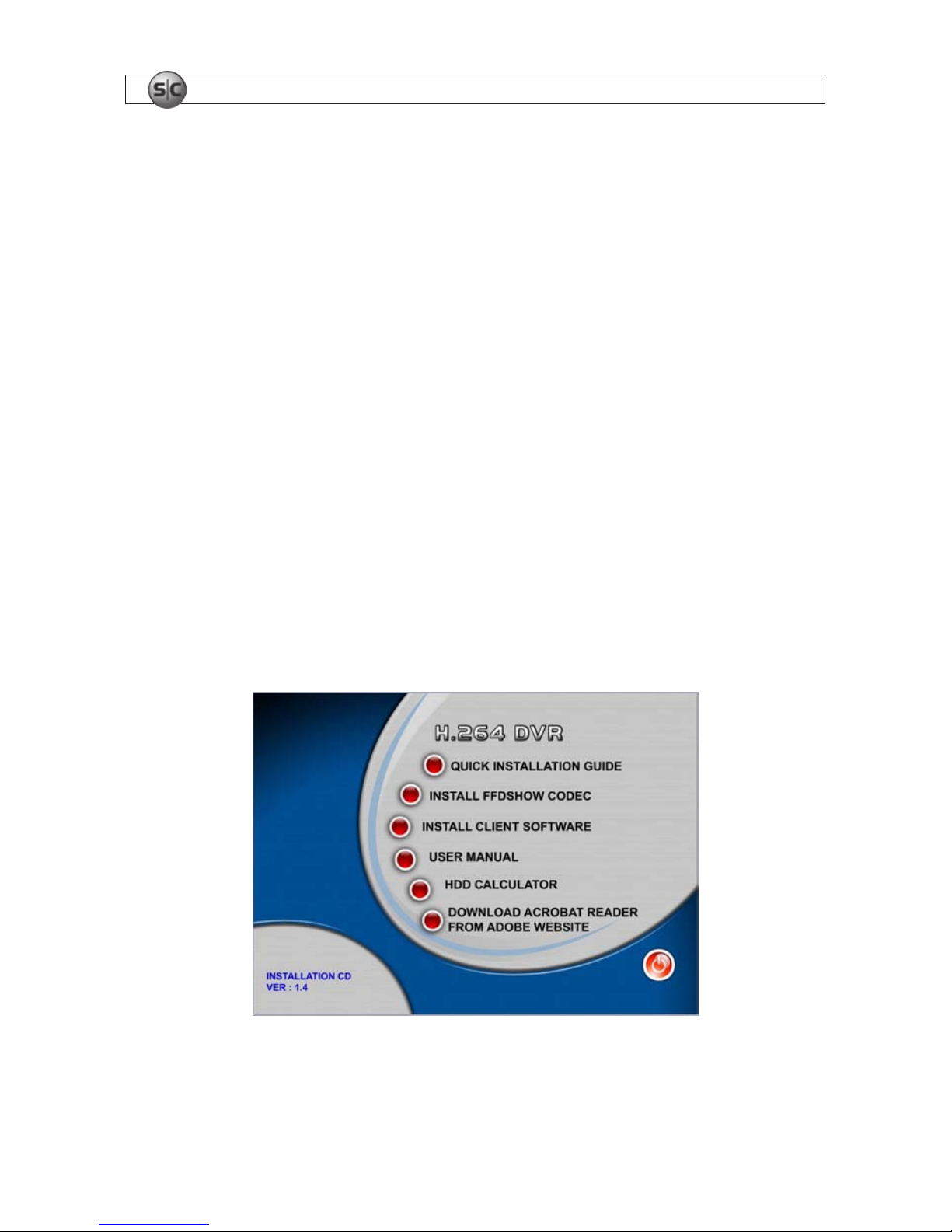
1.2.1 Software CD
The software CD included with your DVR contains:
• Quick Installation Guide
• FFDSHOW codec (see Appendix B)
• Client Software (MClient, see Section 7)
• User manual (this document)
• HDD calculator – for determining recording capacity of your hard disk drive
• Link to download Adobe Acrobat Reader for viewing documentation

3H.264 4-Channel DVR User Manual
SECTION 2: HARDWARE OVERVIEW
SECTION 2
Hardware Overview
2.1 Front panel
Channel Number (1~0) Video Display Controls Menu Navigation Controls
Playback Motion Controls
SETUP, ESC, PTZ
Table 1. DVR front panel controls
Name Description
NUMBER (1~0) Selec t channel with number butto n (1 ~ 4 only)
SEQ
Auto sequence of channels in full screen mode. (Toggle)
PTZ Enter PT Z (Pan, Tilt, Zoom) mo de for PTZ enabled cameras
SETUP Enter SYSTEM SE TUP menu
SEARCH
Enter Search menu .--> Event search / T imeline search / Log / Archive search
/ II
Can be us e as “Play” and “Pau se” function during playb ack
BACKUP
Archive in LIVE (backup Live pic ture) or PLAYBACK (backup pic ture and vide o) modes.
tt
Rewind the footage at 1x, 2 x, and 4x speed in PLAYBACK mode.
t
Jump/Step backward. – In PL AY BACK mode, the playback p osition moves 60 seconds backward
u
Jump/Step forward – In PL AYBACK mode, the playb ack position moves 60 seconds for ward.
uu
Fast for ward the foot age at 1x, 2x, and 4x speeds in PLAYBACK mode
REC Start and stop recording manually
UP (
)
Scroll up in the system menu or select c amera 1 in LIVE mode. It is als o used to enter th e number 1.
RIGHT (u)
Move right, change value s in system menu, or sele ct camera 2 in LIVE mode. It is also used to enter the number 2.
DOWN ()
Scroll down in the system menu or s elect camera 3 in LIVE mode. It i s also used to enter the number 3.
LEFT (t)
Move lef t, change values in system menu, or select c amera 4 in LIVE mode. Also u sed to enter the number 4.
Enter Selec t full screen or quad view in LIVE display mode
ESC Retur n or cancel command
4
www.supercircuits.com
SECTION 2: HARDWARE OVERVIEW
Table 2. Front panel LEDs and connectors
Name Description
HDD
Solid light when DVR is accessing the hard disk.
POWER Solid light when DVR is powered on.
USB USB por t for backup and software update s.
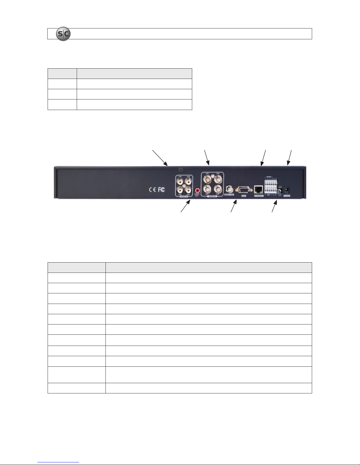
2.2 Backpanel
Audio Channel Inputs Video Channel Inputs PowerEthernet
Audio Out Port
VGA Out Ports VGA/CVBS Switch
DVR rear panel
Table 3. Rear panel connectors and switches
Label Operation
VIDEO IN
4 channel connec tors for vid eo input. Connect camera output to Video -in.
VIDEO OUT 1 connec tor for vide o output.
VGA Connec tor for VGA monitor
AUDIO Audio 1~4:AUDIO IN/ADUIO OUT
SENSOR IN Connec tion for sensor device
ALARM OUT
1 alarm device output. P rovides simple On/O s witching by using relay. 0.5A/125V, 1A/30V
RS-485
Connec t to PTZ camera, +
PTZ D+ . – PT Z D–
LAN R J-45 connec tor for LAN connec tion
DC 12V Apply 12V DC using the D C adapter supplied with the reco rder
VGA / CVBS switch
Selec t either VGA monitor or C VBS (Composite Video Blanking Sync) monitor. DO NOT CHANGE THIS SE TTING WHEN DV R IS
ON. DVR MUST REBOOT IF THIS SWITCH IS CHANGED.
T-ON/ T-OFF switc h For manu facture use only
5H.264 4-Channel DVR User Manual
SECTION 2: HARDWARE OVERVIEW
2.3 DVR Hard disk drive
The hard disk drive (HDD) included in your system is a security grade device, factory tested and certied to be functional for all
operations of the DVR.
CAUTION
Do not open the cover of your DVR. Opening the cover will void the warranty.
If you need to change the HDD installed in your DVR (voids warranty), refer to the HDD Compatibility List in Appendix A for
recommended models.
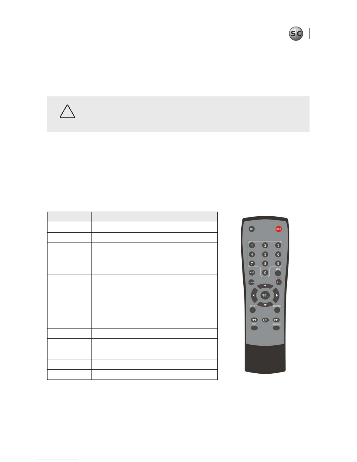
2.4 Remote control
Table 4. Remote control controls
Button Description
ID DVR ID setup
REC Record manually
NUMBER Press number button to select channel
tt
Fast Rewind
uu
Fast For ward
u/ II
Play/Pause
u
PTZ/ Jump/Step forward
t
Jump/Step backward
SEL E nter
DIREC TION Direc tion or number 1 to 4
SETUP Setup m enu screen
SEARCH S earch menu scre en
ESC Es c
BACKUP
Archive and backup still image or v ideo clip.
SEQ Sequential channel conver sion
6
www.supercircuits.com
SECTION 3: SYSTEM SETUP
SECTION 3
System Setup
Use the SETUP menu options to congure your DVR to perform optimally within your installation environment and to meet your
specic security needs.
3.1 SETUP screen
After pressing the SETUP button, the DVR will prompt you for password. The default password is 1111.
CAUTION
Supercircuits highly recommends that the DVR password be changed during initial setup.
Use the menu navigation buttons (up , right u , down , and left t representing 1, 2, 3, and 4 respectively) or the number
keys to enter the password, then press ENTER
for password validation.
1
3
2
4
Menu navigation buttons
After the password is entered, the SETUP icons will appear Use the navigate buttons to select a SETUP item. Press ENTER to open
the menu and set options.
7H.264 4-Channel DVR User Manual
SECTION 3: SYSTEM SETUP
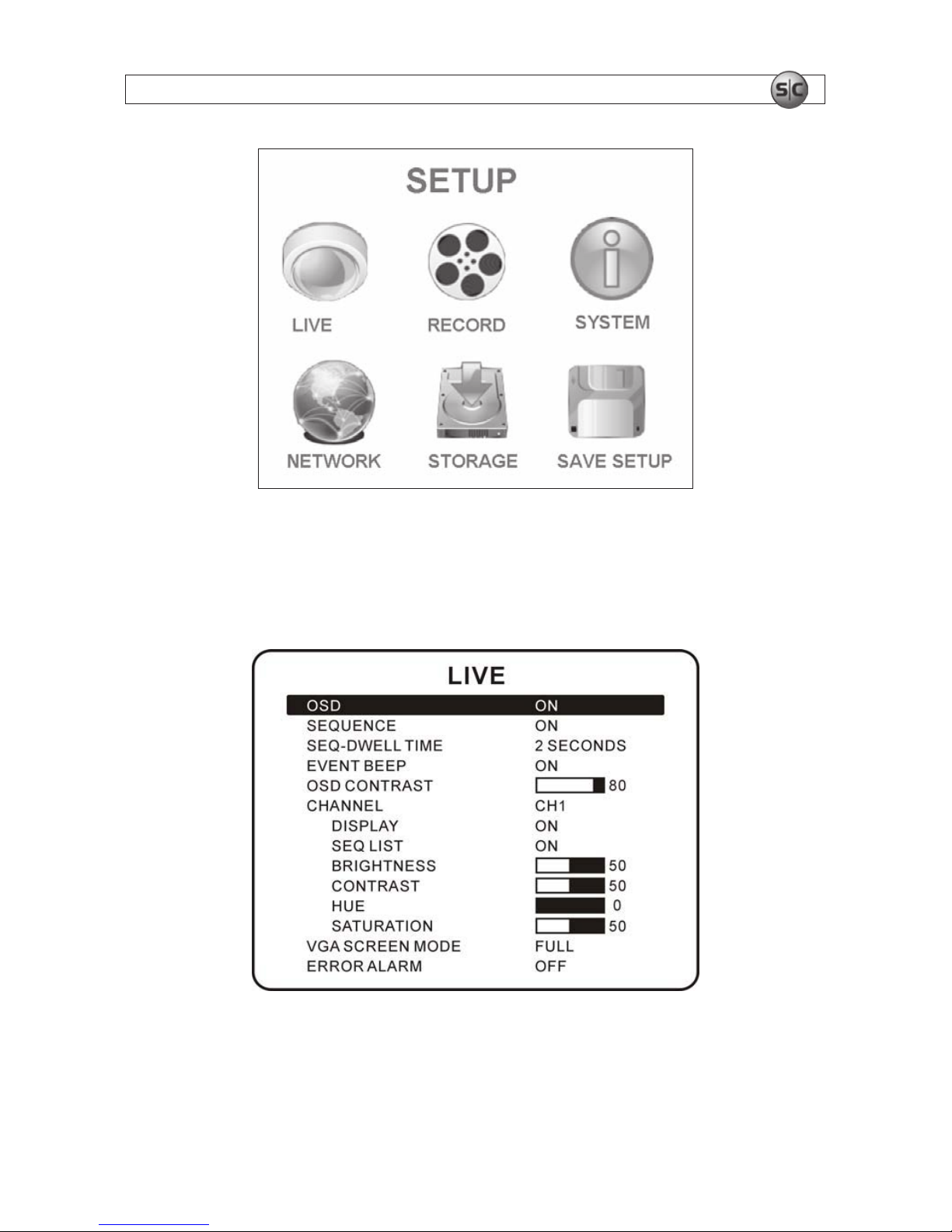
3.2 LIVE mode setup options
In the LIVE mode menu you can adjust how video images from the cameras appear on the monitor. Navigate through the menu
items by pressing the and buttons. Use the t and u buttons to modify a setting.
Setup LIVE screen
8
www.supercircuits.com
SECTION 3: SYSTEM SETUP
Table 5. Menu items in LIVE mode setup
Item Descripti on
OSD
Enable/disable on-sc reen displays (OSD).
SEQUENCE Enable/disable sequential display of video channels in full scre en mode.
SEQ-DWELL TIME Dwell time for each channel display in sequential display mode.
EVENT BEEP Enable/disable internal beep alert sound.
OSD CONTR AST Set the visibility level of the OSD.
CHANNEL Select t he channel for ap plying the following settings.
DISPLAY Enable/disable display of the v ideo channel in L IVE mode.
SEQ LIST Enable/disable the specied channel shown in sequential disp lay mode.
BRIGHTNESS Change t he brightness level f or the specied channel.
CONTRAST Change the contra st level for the speci ed channel.
HUE Change t he hue level for the spec ied channel.
SATURATION Change the saturation level for the specied channel.
VGA SCREEN MODE Selec t VGA screen mo de as either FUL L or Normal.
Table 6. Event BEEP alarm/motion function
Event Beep On Event Beep O
Buzzer Relay Out Buzzer Relay Out
Alarm Yes Yes No Yes
Motion Yes Yes No Yes
NOTE
The “Event Beep” function is NOT related to relay output. Relay output is setup in the RECORD menu.
3.3 RECORD setup options
Set the options for recording video from each channel. Navigate through menu items by pressing the and buttons. Change
the value of the menu item with the t and u buttons.

9H.264 4-Channel DVR User Manual
SECTION 3: SYSTEM SETUP
Setup RECORD screen
Table 7. Menu items in Setup RECORD
Menu item Description
RESOLUTION Set res olution to either 704 x 4 80 or 352 x 240
CHANNEL Selec t the camera channel for which these s ettings apply
FRAME RATE
Set the frame r ate for the specied channel. The sum of t he frames rates of all channels c annot exceed maximum frame r ate
for the r esolution selec ted.
Maximum frame rates are 120 fps for 352 x 240 res olution and 30 f ps for 704 x 480 resolu tion.
QUALIT Y Selec t the recording qualit y for the specied channel f rom NORMAL / HIGH / SUPER.
RECORDING Assign the recording mode for each channel: CONTINUOUS / BY MOTION / BY SENSOR / BY SCHEDULE / DISABLE.
MOTION ZONE
Selec t FULL ZONE or PARTIAL ZO NE motion sensing. If PARTIAL ZONE is chosen, th e screen chang es to enable/disable motion
sensing in each of 14 0 (14 x 10) image segments.
MOTION SE NSITIVITY Set the motion s ensitivit y for the specied channel. Adjust the motion sensitivit y from 1 to 9.
SENSOR T YPE Set the sensor type for the channel to either “–“ (none), N/O (normal open), or N/C (normal closed).
PRE RECORD Enable/disable pre-event recording. Pre- event recording time is 3 s ec. Only intra-frames are r ecorded for pre-e vent recording.
POST EVENT RECORD Se t post event recording time duration up to 30 seconds for t he specied channel
ALARM Enable/disable alarm gen eration for the spec ied channel
ALARM DURATION Set alarm time dur ation for the sp ecied channel
AUDIO Enable/disable audio for the spe cied channel
SCHEDULE Set recording schedule

10
www.supercircuits.com
SECTION 3: SYSTEM SETUP
NOTE
To receive smooth video during playback, set the frame rate of each channel for more than 3fps. Switch to full screen
during playback when audio recording is enabled.
3.3.1 PARTIAL ZONE settings
After selecting PARTIAL ZONE in the MOTION ZONE menu, select the portion of the camera video within which motion sensing
will occur. Each block in the MOTION ZONE display shown below represents a specic segment of the camera video image. Use the
navigation buttons on the front panel to move to each block, and press Enter button to enable or disable motion sensing in that
portion of the video. Areas selected for motion sensing are indicated by a color change of the block. By default, only the area in the
middle of the camera video is monitored for motion.
Motion Zone selection screen with default selections
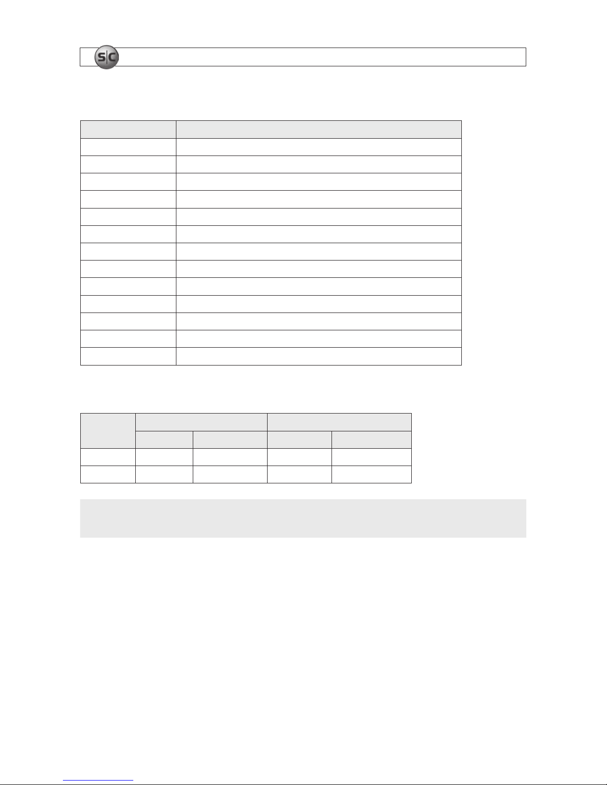
3.3.2 RECORD SCHEDULE
Select SCHEDULE in the RECORD menu to setup the record schedule for the camera channel. In the SCHEDULE menu, use the
navigation buttons on the front panel to move to each option on the screen.
[ALL]: Press Enter to apply to the entire time zone and all channels.
[SUN to SAT]: Press Enter to apply to the entire time zone for the specied channel.
[ENTER]: When a time slot is selected, press ENTER repeatedly to cycle through the options C (continuous), M (motion), S (sensor),
or disable recording mode.
11H.264 Network IP Camera User Manual
SECTION 3: SYSTEM SETUP
[COPY FROM, COPY TO]: Copy the Record schedule of one channel to another channel.
[ESC]: Return to the RECORD setup menu.
SCHEDULE recording setup screen
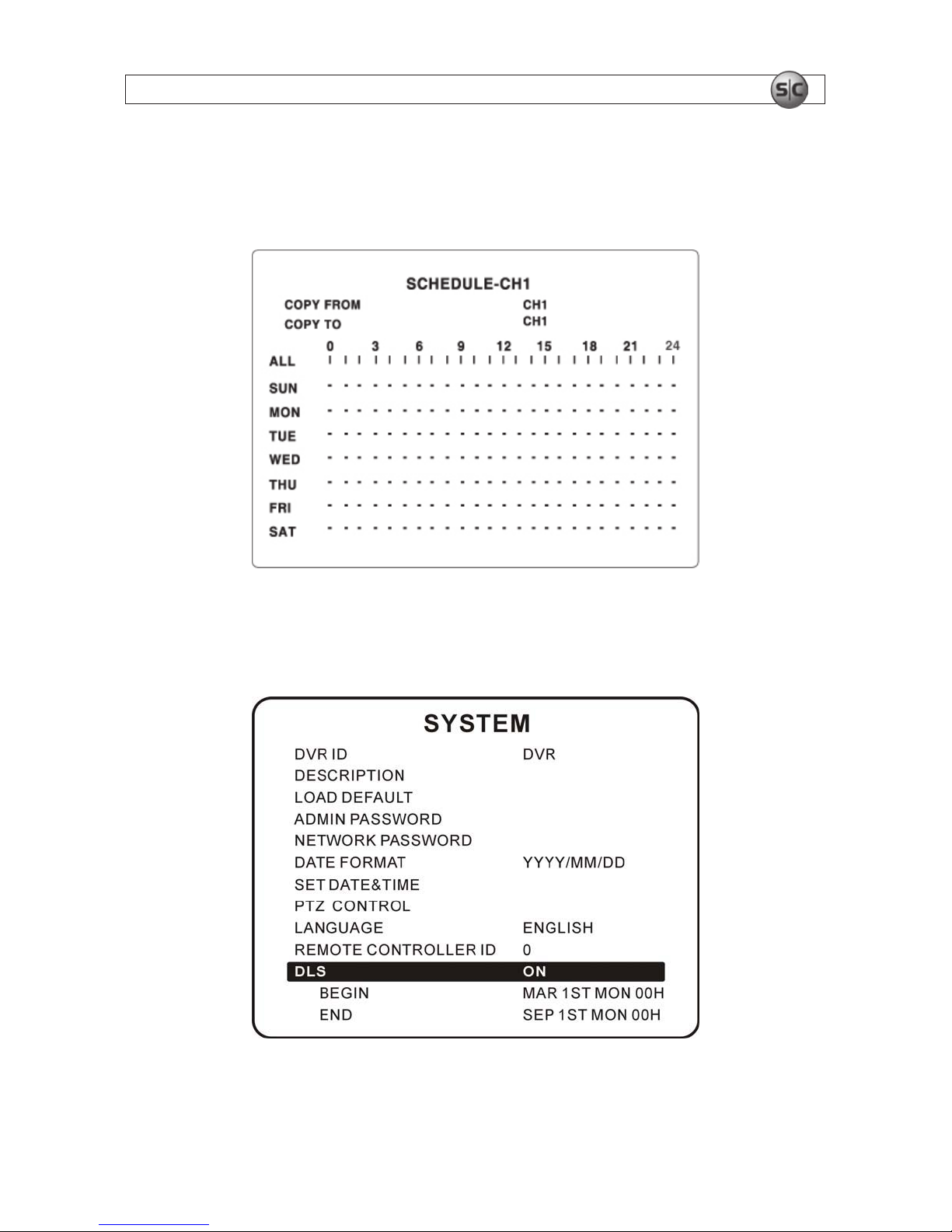
3.4 SYSTEM SETUP mode
SYSTEM setup screen
12
www.supercircuits.com
SECTION 3: SYSTEM SETUP
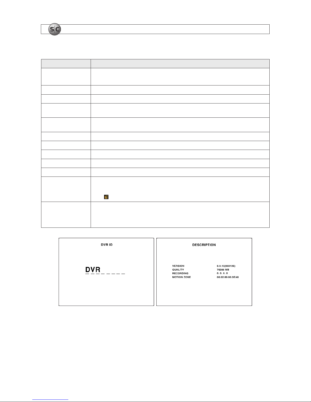
Table 8. Menu items in SYSTEM SETUP screen
Item Description
DVR ID
The name of the system. Press the ENTER to select this item. Select a char acter position with the and buttons. Press
t or u to change the character.
DESCRIPTIO N Press ENTER to see system information.
LOAD DEFAULT Choo se OFF or ON. If selecting ON, press ENTER to load defaul ts.
ADMIN PASSWORD Set the administrator password. The password numbers (1,2,3,4) can be entered w ith the direc tion keys or number keys. The
default pass word is 1111.
NETWORK PASSWORD Se t the networ k client password. The password numb ers (1,2,3,4) can b e entered with t he direction keys or number keys.
The def ault password is 1111.
DATE FORMAT S elect the preferred date and time display format.
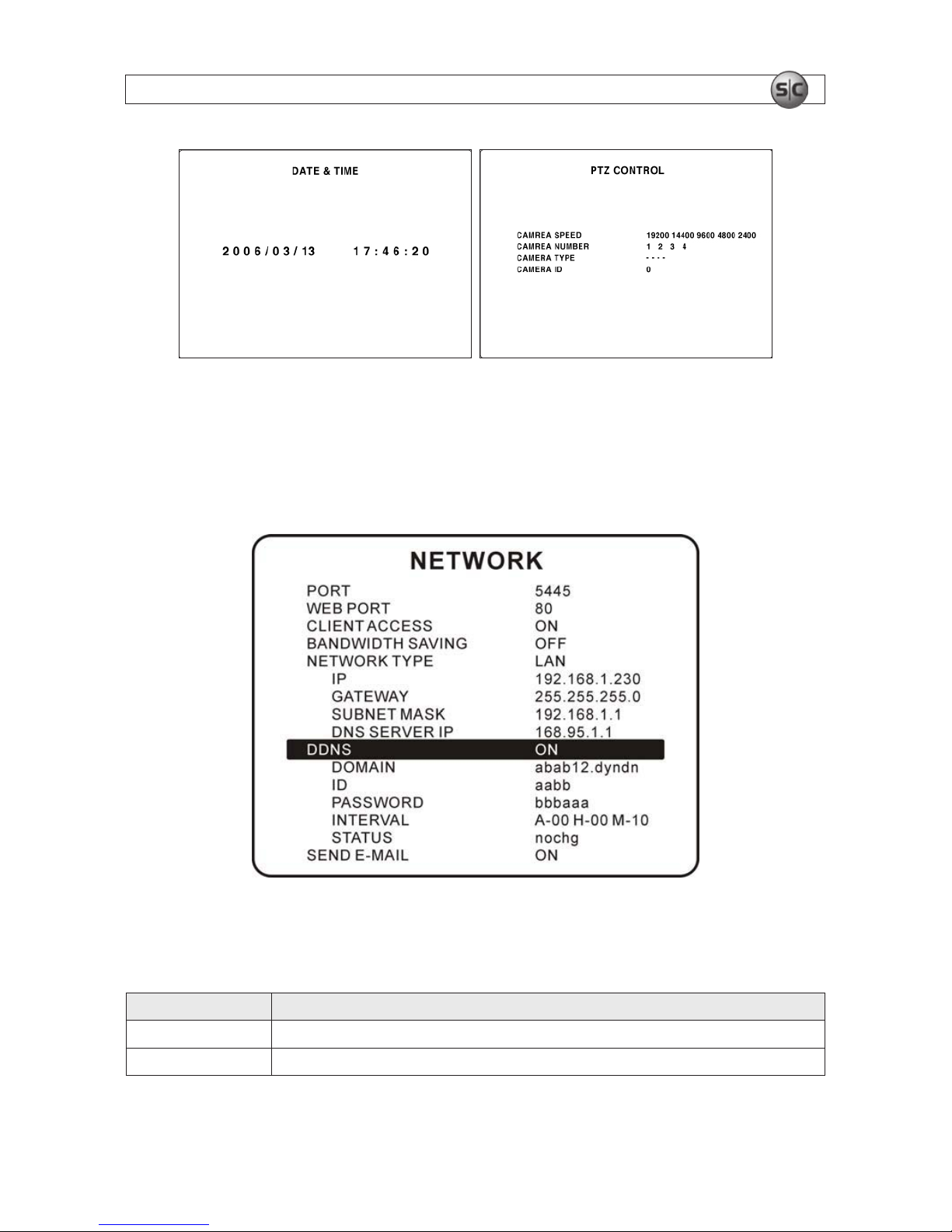
SET DATE & TIME Set the present date and time. If DLS (daylight s avings) is ON, user c an not enter this menu or chan ge the date and tim e.
PTZ CONT ROL S et the camera speed, number, ty pe and ID.
KEY TONE Enable/disable the key tone.
LANGUAGE Select system language.
REMOTE CONTROL ID Se lect the ID of the remote control. (Default is 0).
1. Selec t ID from 0 to 9.
2. On a remote control, pres s the same number as the remote cont rol ID set in DVR.
3. The icon is displaye d in the LIVE screen of the DVR that re sponds to the remote cont rol.
DLS
Set to ON or OFF for DLS (Daylight Sav ing) using the t or u buttons. Af ter select ing ON, move the cursor to BEGIN (MM/
DD/HH) and p ress the SELECT but ton to set the start time of DL S. Move to END (MM/DD/HH) using or but ton to set
the sto p time of DLS. CAUTION: DL S can’t start from 23:00. Also, DLS can’t be applied if the BEGIN an d END dates are the
same.
DVR ID setup screen Description display screen
13H.264 Network IP Camera User Manual
SECTION 3: SYSTEM SETUP
DATE & TIME setup screen PTZ CONTROL screen
3.5 NETWORK setup
Setup network parameters on the NETWORK setup screen.
NETWORK setup screen
Table 9. Menu items in the NETWORK setup screen
Item Description
PORT
Video Port number (def ault:8000); BACKUP por t number is PORT number + 1.
WEB PORT IE Browser port number (def ault: 80)

14
www.supercircuits.com
SECTION 3: SYSTEM SETUP
Item Description
CLIENT ACCESS
Set to ON or OFF to enable or dis able remote access through client sof tware.
BANDWIDTH SAVING Set to ON or OFF for key frame transmissio n. ON is favorable for us e in low-bandwidth networ ks. Set to OFF f or normal use.
NETWORK TY PE Set the ty pe of networ k connectio n: LAN, DHCP, or ADSL. NOTE: Options p resented on the Network Se tup screen suppor t the
type of network se lected.
DHCP When DHCP is sele cted, the DVR gets it s IP address from a DHCP server. The IP address may change occasionally.
ADSL (PPPoE) A registered ID and Password are required fo r an ADSL connection.
LAN IP: Register IP address that is assigned to the DVR. Gateway: R egister Net work Gateway. Subnet Mask: Register N etwork
Subnet Mask. DNS Server IP: Register Network DNS S erver IP
DDNS Support for DynDNS.com
SEND- E-MAIL S end e-mail when IP addre ss changes or an Event happ ens.
3.5.1 Ports
For remote access (from outside the LAN or the Internet) to one or more DVRs connected to the same IP sharing device (LAN), each
DVR must be assigned a unique WEB PORT number. The WEB PORT number in the NETWORK setup screen is the port assigned to
the DVR in the IP sharing device (router).
Additionally the DVR requires two additional ports on the IP sharing device: one to transmit video and the other to transmit
BACKUP les. The video port number is dened in the PORT entry, and the BACKUP port number is always the PORT number +1. For
instance, in the NETWORK screen shown above, the PORT number is 5445, so the DVR will use port 5446 for BACKUP.
The ports dened for a DVR, including the PORT, WEB PORT, and BACKUP (WEB PORT +1) must not be used by other device on the
local network. To access the DVR from outside the local network, the network router the must be setup to “port forward” (associate)
these three ports to the IP address of the DVR. For more information on port forwarding, see http://portforward.com/.
3.5.2 Network types
The DVR supports three types of networks: LAN, DHCP, and ADSL.
LAN
In a LAN conguration the IP address of the DVR is static (xed). If your LAN is maintained by a network administrator, obtain the
static IP address from the administrator.
DHCP
Select DHCP when the IP address is automatically assigned by the DHCP server. The DHCP server assigns the IP address and other
parameters automatically to devices on the LAN not congured with static (unchanging) IP addresses.
 Loading...